

Page 1

pro
2017
Page 2

Hayes Performance Systems
5800 W. Donges Bay Rd.
Mequon, WI 53092
Tel: 888.686.3472
Email: techsupport@hayesbicycle.com
Web: www.hayescomponents.com
Hayes Components Europe
Dirnismaning 20 a
85748 Garching (b. Munich)
Germany
ph: +49 (0)89 203237450
Email: techsupportEU@hayesbicycle.com
Web: www.hayescomponents.com
2
MATTOC PRO SERVICE MANUAL
Page 3
INTRODUCTION
This manual is intended to guide the user through the steps necessary to fully service and maintain
the 2017 Mattoc Pro suspension fork.
We highly recommend that service to this fork be performed by a certied
bicycle mechanic. Failure to follow instructions presented in this manual could lead to serious
injury or death. Any questions about the servicing of this fork or the manual itself should be
directed to Manitou Customer Support at:
Phone: 888-686-3472
Email: techsupport@hayesbicycle.com
Suspension forks by design can contain pre-loaded springs, gases and uids under
extreme pressures. Warnings contained in this manual must be observed to avoid damage to fork,
serious injury or even death.
MATTOC PRO SERVICE MANUAL
3
Page 4

TABLE OF CONTENTS
SECTI ON PAGE NUMB ER
REQUIRED TOOLS 5
EXPLODED DIAGRAM 6–10
CASTING REMOVAL & SERVICE 12–14
AIR SPRING SERVICE 15–19
DAMPER SERVICE 20–23
CASTING INSTALLATION 24–26
COMPRESSION DAMPER INSTALL 27–30
TRAVEL CHANGE (OPTIONAL) 31-33
4
MATTOC PRO SERVICE MANUAL
Page 5

REQUIRED TOOLS
Below is a list of tools necessary for servicing the 2017 Mattoc Pro fork.
• Safety Glasses
• Nitrile Gloves
• Lint-Free Rags
• Torque Wrench
• Slickoleum™ Grease
• Semi-bath Oil, 5/40w Synthetic - Manitou part number 85-0022
• 5wt Maxima Fork oil - Manitou part number 85-0023
• Manitou Tool Kit - Manitou part number 172-31133
(This includes the Manitou Cassette Tool, 8mm thin wall socket, and at
ground 24mm socket)
• 8mm Hex Wrench
• 2mm Hex Wrench
• 20mm Socket
• 22mm Box end Wrench
• 12mm Box End Wrench
• 12mm Socket
• Ratchet
• 22mm Crow’s Foot
• Fork/Shock Pump
• Pick
• Adjustable Wrench
• Downhill tire lever or at blade screwdriver
MATTOC PRO SERVICE MANUAL
5
Page 6

MAttoc Pro 110 27.5 Exploded view
6
MATTOC PRO SERVICE MANUAL
Page 7
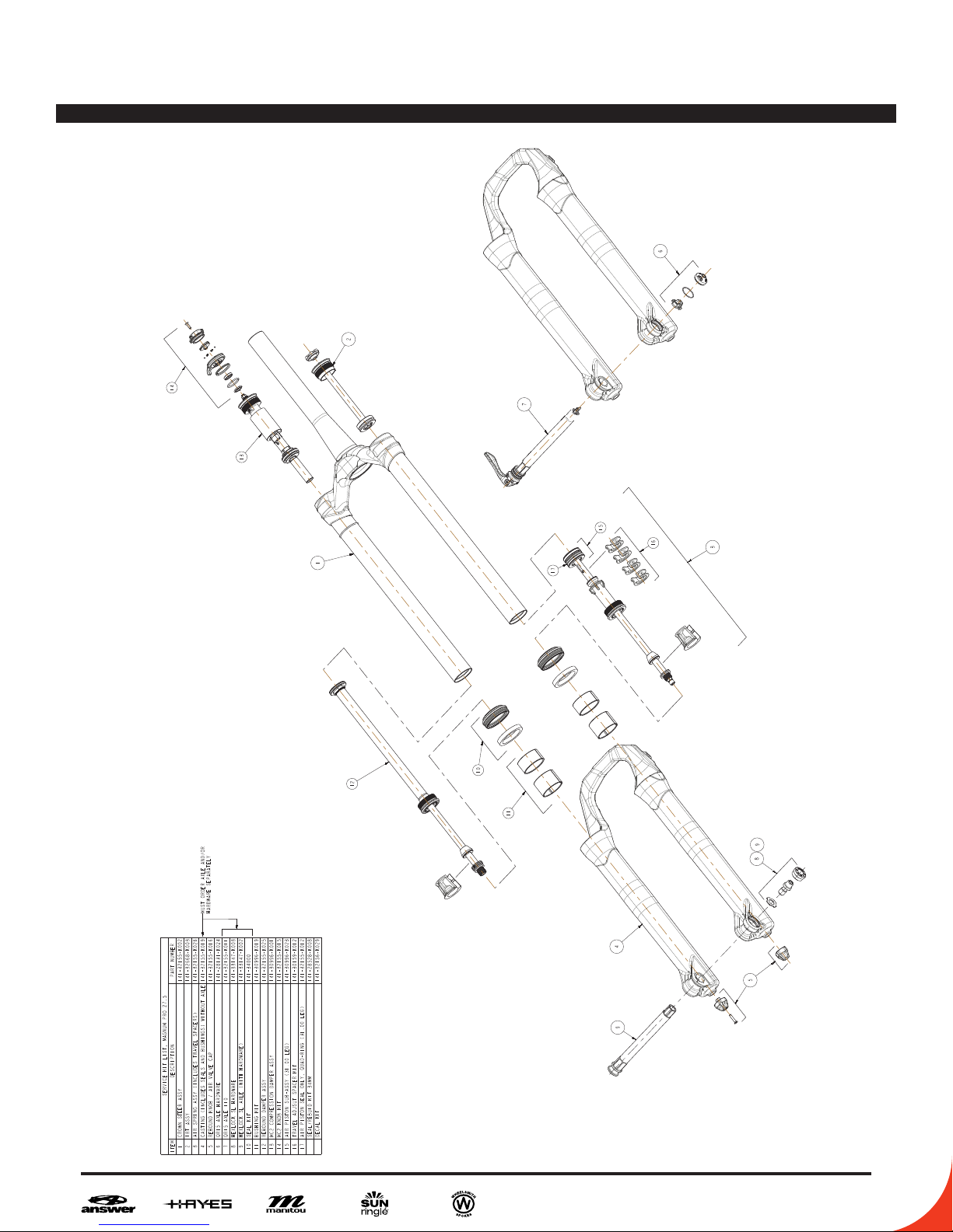
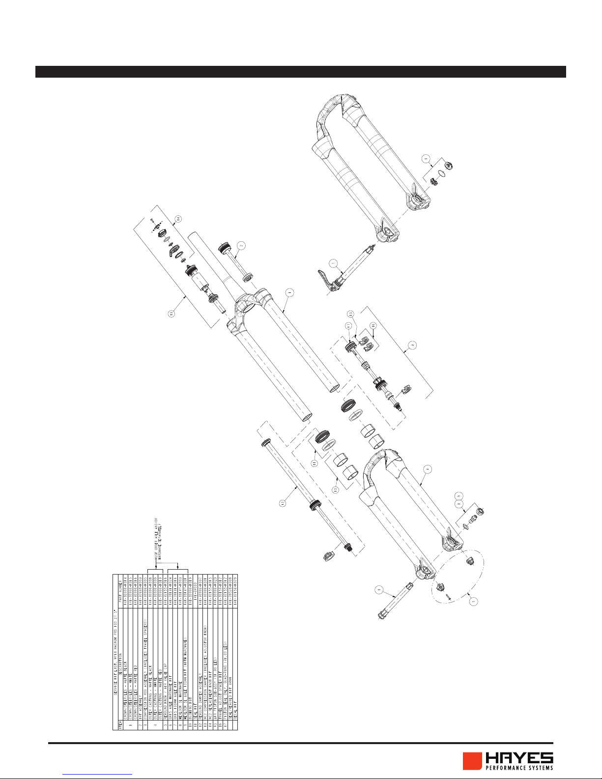
Magnum Pro 110 27.5+/29 Exploded view
MATTOC PRO SERVICE MANUAL
7
Page 8
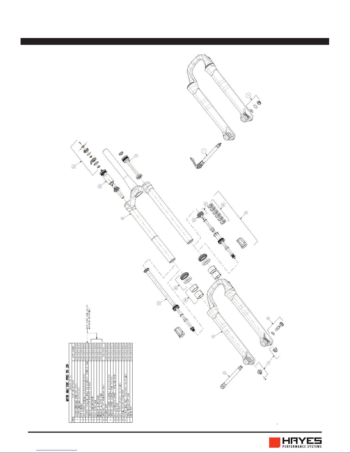
MAttoc Pro 110 29+ Exploded view
8
MATTOC PRO SERVICE MANUAL
Page 9
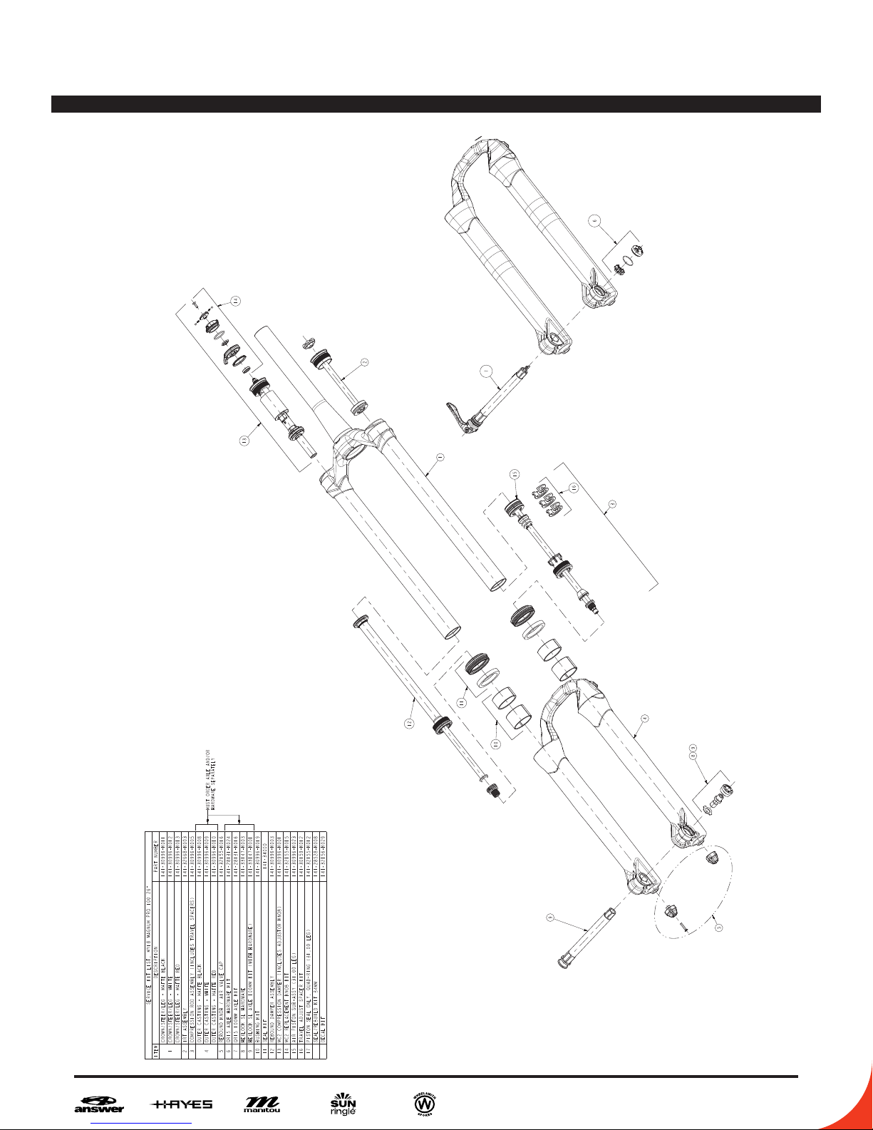
MAttoc Pro 100 26 Exploded view
MATTOC PRO SERVICE MANUAL
9
Page 10
MAttoc Pro 100 27.5 Exploded view
10
MATTOC PRO SERVICE MANUAL
Page 11
HAYES PERFORMANCE SYSTEMS WARRANTY
Limited Warranty:
HAYES warrants its products to be free from defects in materials or workmanship under
normal intended use for a period of one year (two years in European Union countries) from
the date of purchase, subject to normal wear and tear. Unless otherwise prohibited by law,
any such defective products will be repaired or replaced at the option of HAYES when received
with proof of purchase, freight prepaid. This warranty does not cover breakage, bending, or
damage that may result from crashes or falls. This warranty does not cover any defects or
damage caused by alterations or modications of HAYES products or by normal wear, accidents,
improper maintenance, damages caused by the use of HAYES products with parts of dierent
manufacturers, improper use or abuse of the product, application or uses other than those
set forth in the HAYES instruction manual or failure to follow the instructions contained in
the applicable HAYES instruction manual. Instruction manuals can be found on-line at www.
hayescomponents.com. Any modications made by the BUYER or any subsequent user will
render the warranty null and void. This warranty does not apply when the serial number or
production code has been deliberately altered, defaced or removed from the product. The cost
of normal maintenance or replacement of service items, which are not defective, shall be the
BUYER’s responsibility. If permitted by local law, this warranty is expressly in lieu of all other
warranties (except as to title), express or implied, and in particular and without limitation HAYES
disclaims the implied warranties of merchantability or tness for purpose If for any reason
warranty work is necessary, return the component to the place of purchase or contact your
dealer or local HAYES distributor. In the USA, contact HAYES for a return authorization number
(RA#) at (888) 686-3472. At that time, instructions for repair, return, or replacement shall be
given. Customers in countries other than the USA should contact their dealer or local HAYES
distributor.
Limitation of Liability.
Unless required by mandatory law, HAYES shall not be liable for any incidental, indirect, special
or consequential damages.
This warranty does not apply to normal wear and tear. Wear and tear parts are subject to
damage through normal use, failure to service according to recommendations or riding in
conditions other than recommended. The cost of normal maintenance or replacement of service
items, which are not defective, shall be paid for by the original purchaser. Wear and tear parts
that will not be replaced under warranty include but are not limited to the following:
Bushings Dust Seals Stripped or Worn Bolts
Rear Shock Fork/Shock Air Seals and/or O-rings Remote Lockout Cable
Mount Hardware Bearings Gloves
Handlebar grips Upper Stanchion Tubes Lower Stanchion Tubes(Dorado)
Tubeless Valves
MATTOC PRO SERVICE MANUAL
11
Page 12

CASTING REMOVAL & SERVICE
Remove rebound knob using a 2mm Hex
1
2
wrench.
Insert a 8mm Hex wrench into the end of
the rebound rod and loosen clockwise
until rebound rod disengages from the
casting threads.
3
12
Unscrew air cap and depress Schrader
Valve a few times to ensure all air is
released.
MATTOC PRO SERVICE MANUAL
Page 13

CASTING REMOVAL & SERVICE
Using the Manitou 8mm Thin Wall
4
5
Socket, turn the compression rod
clockwise until compression rod is
disengaged from the casting threads.
Remove casting from fork. It is
recommended this be done over a drain
pan as the lower casting contains semibath oil. Allow oil in casting to drain out
before continuing to next step.
Using a downhill tire lever or similar
6
tool, gently pry the dust seals out of the
casting.
MATTOC PRO SERVICE MANUAL
13
Page 14

CASTING REMOVAL & SERVICE
Remove old foam wiper rings. Apply
7
8
semi-bath uid to the new foam
wiper rings and install into fork
casting.
Remove springs from lip of dust seals.
Clean seal area with Isopropyl alcohol.
Using the Manitou 34mm Seal Press
or large socket press in the dust seals.
Reinstall springs onto seals.
14
MATTOC PRO SERVICE MANUAL
Page 15

AIR SPRING SERVICE
Make sure the air is released from the
1
2
fork. Depress IRT and Compression Rod
Schrader valves a few times to ensure
all air is released.
Remove IRT using a 24mm socket.
Pull IRT assembly straight out.
3
MATTOC PRO SERVICE MANUAL
15
Page 16

AIR SPRING SERVICE
Invert the fork and use Manitou cassette
3
4
tool with adjustable wrench to unthread
the air spring assembly from the
stanchion.
Remove Air Spring Assembly, clean with
isopropyl, and re-grease.
Once the air spring assembly is removed
5
16
clean the inside of the stanchion with
isopropyl alcohol and a lint free towel (Be
careful to not scratch the inner surface
of the stanchion). Inspect the inside and
outside of the stanchion for scratches or
other damage.
MATTOC PRO SERVICE MANUAL
Page 17

AIR SPRING SERVICE
Liberally grease the piston quad seal
6
7
and outer surface with Slickoleum™
grease. Add 8cc’s of Slickoleum™
grease to the top of the air piston.
Add Slickoleum™ grease to the
stanchion threads before inserting the
air spring assembly. Spread grease
across entire thread surface.
Install air spring assembly into
8
stanchion. Using a 26mm crow’s foot
and Manitou cassette tool, torque to
60-80 in lb [6.8-9.0 N m].
MATTOC PRO SERVICE MANUAL
17
Page 18

AIR SPRING SERVICE
Liberally grease the IRT piston seal and
9
10
outer surface with Slickoleum™ grease.
Apply Slickoleum™ grease to the
threads of the stanchion.
Insert IRT piston into stanchion. Apply
even pressure to piston surface as you
work the piston seal past the stanchion
threads.
Install IRT into stanchion. Torque to
11
18
60-80 in lb [6.8-9.0 N m].
MATTOC PRO SERVICE MANUAL
Page 19

AIR SPRING SERVICE
Attach a shock pump and inate IRT to
12
13
100PSI.
NOTE: ALWAYS SET IRT PRESSURE
BEFORE COMPRESSION ROD
ASSEMBLY.
Attach a shock pump and inate air leg
to 60PSI. This will aid in installing the
casting later.
MATTOC PRO SERVICE MANUAL
19
Page 20

DAMPER SERVICE
Using a 2mm Hex wrench remove the
1
2
screw of the MC2 knob.
Note: Be sure to hold the HBO knob still
while removing the screw/nut. These
tend to move and can damage the
damper if the knob is over turned.
Remove the black high speed
compression knob while keeping the
silver HBO knob in place.
20
MATTOC PRO SERVICE MANUAL
Page 21

DAMPER SERVICE
With a 13mm socket, unthread the
3
exposed nut and remove the red low
speed adjustment knob.
Note: Be sure to hold the knob still while
removing the screw/nut. These tend to
move and can damage the damper if the
knob is over turned.
Remove the sliver spacer that was under
4
the red low speed adjustment knob.
MATTOC PRO SERVICE MANUAL
21
Page 22

DAMPER SERVICE
Use the Manitou cassette tool and 1/2
5
6
socket or adjustable wrench to unthread
the compression damper assembly from
the stanchion.
Remove compression damper assembly
from the stanchion.
Pour fork oil into a catch pan.
7
22
MATTOC PRO SERVICE MANUAL
Page 23

DAMPER SERVICE
Using a Manitou cassette tool and
8
9
adjustable wrench, unthread the
rebound damper assembly from the fork
stanchion.
Remove rebound damper assembly from
the fork. Once the damper assembly
is removed, clean the inside of the
stanchion with isopropyl alcohol and a
lint free towel. Inspect the inside and
outside of the stanchion for scratches
and other damage. Inspect rebound
damper for damage and replace if
necessary.
Use a 26mm crow’s foot, Manitou
10
cassette tool, and torque wrench to
install the rebound damper assembly.
Torque to 60-80 in lb [6.8-9.0 N m
MATTOC PRO SERVICE MANUAL
23
Page 24

CASTING INSTALL
Before lling the fork with fork oil and
1
2
installing the MC2 compression damper,
we must rst install the casting. This
ensures a correct oil level. First apply
a generous amount of Slickoleum™
grease to the oil seal/dust seal area of
the casting.
Make sure the air chamber is lled
with air (60PSI). This will extend the
air spring assembly and make casting
installation easier.
Fully extend the rebound damper rod.
3
24
MATTOC PRO SERVICE MANUAL
Page 25

CASTING INSTALL
Slide casting onto the stanchion
4
5
assembly. Only slide the casting down
about halfway at this point. Take care
that the seal lips do not fold over upon
installation.
Insert 15cc of semi-bath into each
casting leg. Once the semi-bath is in the
legs slide the casting the rest of the way
onto the stanchion assembly.
Using an 8mm Hex wrench tighten the
6
rebound damper rod to 35–40 in lb
[3.95–4.5 N m] by turning them counter-
clockwise. Do not overtighten, doing so
can damage the end of the rods.
MATTOC PRO SERVICE MANUAL
25
Page 26

CASTING INSTALL
Install the rebound knob using a 2mm
7
8
Hex wrench. Add a small drop of blue
Loctite to the screw before installation
to prevent the screw from backing out
during riding.
Using the Manitou 8mm Thin Wall
Socket, turn the compression
rod counter-clockwise. Do not
overtighten, doing so can damage the
end of the rods.
26
MATTOC PRO SERVICE MANUAL
Page 27

COMPRESSION DAMPER INSTALL
Pour 5wt Maxima fork oil into the
1
2
damper leg. Fill it up about ¾ full.
Place a lint-free towel over the opening
in the damper leg and compress the fork
10-15 times.
Pour additional 5wt fork oil into the
3
damper leg until the oil height (space
from the top of the damper leg to the top
of the oil) is set at the proper level. See
following page for the correct oil height
depending on compression damper type
and fork travel. An oil height setting tool
used for motorcycle forks similar to the
one pictured makes this job easier.
MATTOC PRO SERVICE MANUAL
27
Page 28

oil height chart 2017-2018
COMPRESSION DAMPER INSTALL
fork model oil height
Mastodon pro
mastodon comp
markhor (80/100mm)
markhor (120mm)
mattoc pro
mattoc comp
machete (abs+)
machete (kwik toggle, 90-120mm)
machete (kwik toggle, 130-140mm)
circus comp/expert
circus sport (ffd)
R7 PRO
dorado (see dorado service guide)
75mm
87mm
92mm
97mm
75mm
87mm
87mm
87mm
91mm
87mm
83mm
83mm
180-190mm
oil
height
(refers to the air
space between the top
of the oil and top of
the fork leg)
note
1. oil height is set with compression damper
removed.
2. oil height is set with fork fully extended
and casting installed.
28
MATTOC PRO SERVICE MANUAL
Page 29

COMPRESSION DAMPER INSTALL
Insert compression damper into the
4
5
damper leg. Ensure the damper is set in
the unlocked position when installing.
Using the Manitou cassette tool and
torque wrench, tighten down the MC2 at
a torque of 60–80 in lb
[6.8–9.0 N m].
Place the silver spacer onto the MC2
6
damper, at side facing up.
MATTOC PRO SERVICE MANUAL
29
Page 30

COMPRESSION DAMPER INSTALL
Place red low speed adjustment knob
7
8
onto damper assembly. With a 13mm
socket, tighten down the nut nger tight
Note: Be sure to hold the knob still while
removing the screw/nut. These tend to
move and can damage the damper if the
knob is over turned.
Place high speed and HBO knob
assembly onto the red low speed
adjustment knob. Tighten down screw
with 2mm Hex wrench.
9
Note: Be sure to hold the HBO knob still
while removing the screw/nut. These
tend to move and can damage the
damper if the knob is over turned.
Clean fork and use a shock pump to
set to desired pressure. Lightly pull the
casing away from the CSA as you add
air. Pressure chart below for reference.
30
MATTOC PRO SERVICE MANUAL
Page 31

Pro & COMP
MATTOC PRO SERVICE MANUAL
31
Page 32

Mattoc travel change
2
2
In order to change the travel of your Mattoc Pro/Comp (26-27.5-29+), rst
remove the compression rod assembly. For instructions on how to do this
refer to page 16. Once the rod is removed arrange the travel spacers into
the desired amount of travel using the following charts.
2017 Mattoc 110mm “Boost” Hub Spacing
27.5”
27.5+/29”
29+
TRAVEL SPACERS
170 0
160 1
150 2
140 3
TRAVEL SPACERS
140 0
130 1
120 2
110 3
100 4
TRAVEL SPACERS
120 2
110 3
100 4
90 5
80 6
29+ TREK
32
MATTOC PRO SERVICE MANUAL
TRAVEL SPACERS
110 0
100 1
90 2
80 3
Page 33

Mattoc travel change
2
2
2017 Mattoc 100mm Hub Spacing
27.5”
TRAVEL SPACERS
160 0
150 1
140 2
26”
2017 Mattoc Comp IVA
TRAVEL SPACERS
170 0
160 1
150 2
140 3
TRAVEL SPACERS
170 0
160 1
150 2
140 3
TRAVEL SPACERS
140 4
130 4
120 3
110 3
100 2
90 2
80 1
MATTOC PRO SERVICE MANUAL
33
Page 34

WWW. MANITOUMTB.COM WWW.HAYESCOMPONENTS.COM
5800 W DONGES BAY ROAD MEQUON WI 53092
 Loading...