

Page 1
C
B
A
Page 2
MANITOU SUSPENSION FORKS
CONGRATULATIONS ON CHOOSING THE LATEST IN SUSPENSION TECHNOLOGY
AVAILABLE, A 2004 MANITOU FORK. This fork
is fully assembled and ready to be installed onto your bicycle. It comes equipped
with a 11/8-inch threadless steerer tube and may also be available in a disc brake
only version. A handlebar-mounted reflector must be used for on-road use, which
is not included with your fork.
2004 MANITOU BLACK FORK LINE
BLACK COMP ...........100 OR 120 MM TRAVEL / COIL SPRING / FLUID FLOW
DAMPING / SINGLE CROWN / RA CASTING
BLACK ELITE ............100 OR 120 MM TRAVEL / COIL SPRING / FLUID FLOW
DAMPING (REBOUND ADJUST) / SINGLE CROWN / RA
CASTING
BLACK SUPER AIR ...80, 100 OR 120 MM TRAVEL / AIR SPRING /
FLUID FLOW DAMPING (REBOUND ADJUST) / SINGLE
CROWN / RA CASTING
BLACK PLATINUM.....90-120 MM RAPID TRAVEL WIND-DOWN /
COIL SPRING / TPC LOCK-OUT / SINGLE CROWN / RA
CASTING
You can also download this manual at www.answerproducts.com.
BICYCLING IS A HAZARDOUS ACTIVITY
THAT REQUIRES THAT THE RIDER STAY IN
CONTROL OF HIS OR HER BICYCLE AT ALL TIMES. READING THIS MANUAL
ENTIRELY AND PROPERLY MAINTAINING YOUR BICYCLE AND SUSPENSION FORK
WILL REDUCE THE POSSIBILITY OF INJURY OR POSSIBLE DEATH. PRIOR TO RIDING YOUR BICYCLE, YOU SHOULD INSPECT YOUR SUSPENSION FORK TO ENSURE
THAT NO DAMAGE HAS OCCURRED DURING THE COURSE OF PREVIOUS RIDING OR
ASSEMBLY. DO NOT RIDE YOUR BICYCLE IF THE FORK SHOWS ANY SIGNS OF
BENDING, CRACKING, CREAKING, LEAKING, OR IF IT IS MISSING ANY OF THE
ORIGINALLY SUPPLIED COMPONENTS. ANY FALL FROM YOUR BICYCLE
CAN RESULT IN SERIOUS INJURY OR EVEN DEATH. FOLLOWING THESE INSTRUCTIONS CAN HELP YOU REDUCE THE RISK OF BEING INJURED. IF YOU ARE A MODERATE OR AGGRESSIVE OFF-ROAD RIDER, OR RIDE AT LEAST THREE TIMES A
WEEK OVER ROUGH TERRAIN, ANSWER RECOMMENDS RETURNING YOUR SUSPENSION FORK EVERY 2 YEARS FOR A THOROUGH INSPECTION AND UPDATE.
TAKE YOUR FORK TO A MANITOU AUTHORIZED DEALER WHO CAN ARRANGE FOR
SHIPMENT TO ANSWER PRODUCTS, OR YOU MAY CALL ANSWER TO HAVE YOUR
FORK SHIPPED DIRECTLY AT (800) 423-0273.
IMPORTANT: The Manitou fork is an off-road fork, and as such, does not
come with proper reflectors for on road use. Have your dealer or mechanic
install proper reflectors to meet the Consumer Product Safety Commission’s
(C.P.S.C.) Requirements for Bicycles if the fork is going to be used on public
roads at any time. If you have questions regarding C.P.S.C. Standards, contact
your dealer.
CONSUMER SAFETY INFORMATION
Never remove or have the steerer tube or stanchions removed from the crown.
The steerer tube and stanchions (inner legs) are press fit at the factory. Press fit
inner legs have higher performance versus bolt-in inner legs, but can not be
pressed out. Pressing them out will permanently damage the crown beyond repair
and render it unsafe for any continued use. Never attempt to thread a threadless
steerer tube. Cutting threads will weaken the steerer tube and cause an unsafe
condition. The only safe thing to do is to obtain the proper crown/steerer from
your dealer, or contact Answer Customer Service at (800) 423-0273. Any other
alteration or modification to your fork should be considered unsafe. Contact
Answer Customer Service prior to modifying your fork in any way for safety information.
Do not use the fork if any parts are broken, bent, cracked, or you suspect may be
damaged. Contact your dealer or Answer Products Customer Service at (800) 4230273 if you have any questions concerning the integrity or condition of your fork.
Answer Products recommends that you periodically inspect your fork for wear and
damage. Inspect the crown, inner legs, outer legs, dropouts and brake arch areas
for cracks or damage.
WARRANTY INFORMATION
Any Answer Products fork found by the factory to be defective in materials and/or
workmanship within one year from the date of purchase (or two years in EU countries) will be repaired or replaced at the option of the manufacturer, free of charge,
when received at the factory, freight prepaid. This warranty does not cover breakage, bending, or damage that may result from crashes or falls. This warranty does
not cover any fork that has been subject to misuse or whose serial number has
been altered, defaced or removed. This warranty does not cover paint damage.
Any modifications made by the user will render the warranty null and void. This
warranty is expressly in lieu of all other warranties, and any implied are limited in
duration to the same duration as the expressed warranty herein. Answer Products
shall not be liable for any incidental or consequential damages.
If for any reason warranty work is necessary, return the fork with original purchase
receipt to the place of purchase. At that time, instructions for repair, return, or
replacement shall be given. Customers in countries other than USA should contact
their dealer or local distributor.
FORK INSTALLATION
1. Remove the old fork from your bicycle.
2. Measure and cut the steerer tube to fit your bicycle head tube (see WARNING
above). You can use your old fork as a guide for cutting the steerer tube
length.
3. Remove the headset crown race from the old fork.
4. Install headset and fork per headset manufacturer’s instructions.
5. Install the handlebars and stem to the stem and handlebar manufacturer’s
instructions.
6. Install the brakes per the brake manufacturer’s instructions.
7. To install the front wheel adjust the front wheel quick release to clear the secondary dropout safety tabs. Secure wheel per quick release manufacturer’s
instructions.
8. Install the brake cable per brake manufacturer instructions. Ensure that the
front brake cable is properly routed. Make sure the brake line is not crimped
or contacts the tire as the fork moves through its travel.
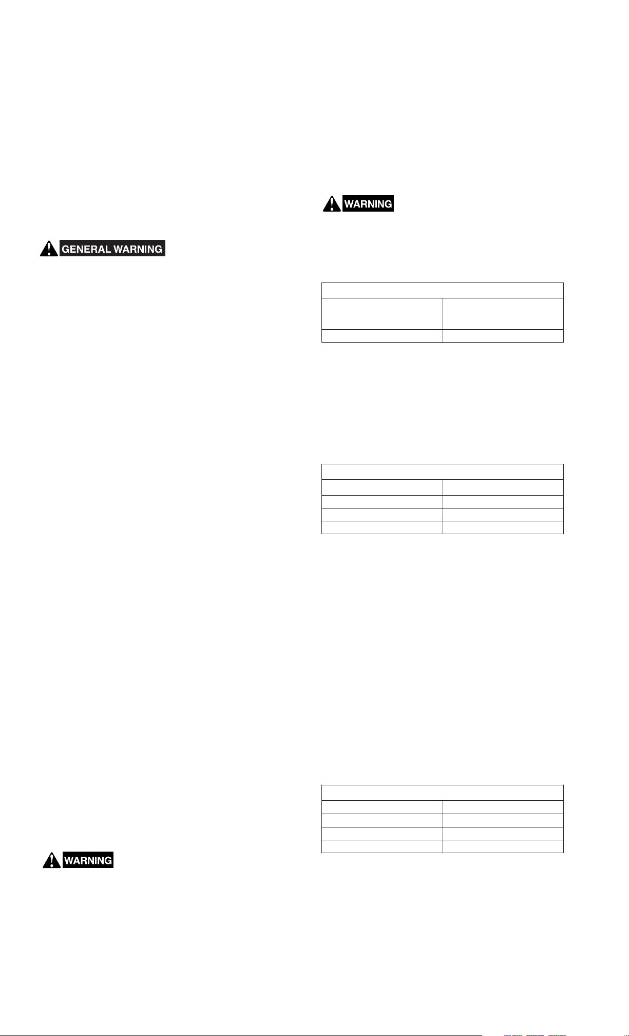
WHEN INSTALLING THE WHEEL WITH A PROPERLY INFLAT-
MINIMUM TIRE CLEARANCE.
1. MEASURE FROM THE HIGHEST POINT ON THE TIRE TO THE BOTTOM OF THE
BRAKE ARCH, SEE FIGURE A. SEE TABLE 1 FOR MINIMUM BRAKE ARCH
CLEARANCE.
2. MEASURE THE TIRE AT MAXIMUM WIDTH, SEE FIGURE B. SEE TABLE 1 FOR
MAXIMUM TIRE WIDTH.
ED TIRE, CHECK TO MAKE SURE THE FORK ACHIEVES
TABLE 1: WHEEL CLEARANCE
MINIMUM BRAKE ARCH CLEAR-
ANCE
(See Figure A)
8.5 mm 60 mm
MAXIMUM
TIRE WIDTH
(See Figure B)
IMPORTANT: Failure to properly route and securely attach the front brake
cable to the fork can cause serious injury or death. This fork should not be used
if any parts appear to be or are damaged. Contact your local dealer or Answer
Products for replacement parts.
INITIAL SET-UP
MEASURING TRAVEL
To determine which travel your fork is in, simply measure the distance from the
top of the seal area on the lowers (or the bottom of the fork boot) to the bottom of
the crown. See Table 2 to determine travel.
TABLE 2: TRAVEL MEASUREMENT
FORK TRAVEL SEAL TO CROWN MEASUREMENT
80 mm Around 101 mm
100 mm Around 121 mm
120 mm Around 141 mm
MEASURING SAG
You’ll need a tape measure, a pencil, a piece of paper and a helper.
1. Measure the distance from the front axle’s centerline to the bottom of the
upper crown when no one’s sitting on the bike and write this distance down.
(Remember the exact locations of the two points because you’ll need to use
them later.)
2. Have the rider sit on the bike and measure the distance between the same
two points as in step one. It’s important to be in the normal riding position
(weight centered) with your feet on the pedals.
3. Subtract the second measurement from the first. The resulting measurement
is the static sag (See Table 3).
4. On coil forks, the preload adjuster on Manitou forks is located on the top left
of the crown (as you are looking at the fork from the rider’s perspective).
Turning the knob clockwise increases spring preload and decreases sag,
while turning the knob counterclockwise decreases spring preload and
increases sag.
5. On air-coil forks, remove the air cap located on the top of the left leg and,
using a dedicated shock pump (Manitou part #85-4069), inflate the fork with
the desired pressure (75% of rider weight for 80 mm travel forks, or 50% of
rider weight for 100 mm and above). Be aware that sometimes air systems
lose a small amount of pressure when the pump is removed, so you may
want to check exactly how much your pump loses by reinstalling it after you
have set and checked pressure.
6. If adjusting the preload or air pressure does not provide the proper sag you
may require a new ride kit. Please see recommended ride kits below.
INSTALLATION INSTRUCTIONS
The steerer tube may need to be cut to length to fit your bicycle head tube. If you
are not familiar with this procedure, or do not have the proper tools to cut the
steerer tube, it is recommended that you seek a dealer with a qualified bicycle
mechanic to perform installation.
THE STEERER TUBE AND STANCHIONS (INNER LEGS) ARE
CANNOT BE REMOVED FROM THE CROWN. REPLACEMENT OF THE ENTIRE
CROWN/STEERER ASSEMBLY MUST BE DONE TO INCREASE STEERER TUBE
LENGTHS OR CHANGE DIAMETERS. REMOVING AND REPLACING THE STEERER
TUBE OR STANCHIONS WILL RESULT IN AN UNSAFE CONDITION AND SHOULD
NEVER BE DONE.
BREAK-IN
Your new fork is designed to break in during your first few rides (about 20 hours
total riding time). Prior to break-in, you may notice your fork feels tight and slightly notchy. Following the break-in period, your fork will feel much smoother and
will react to bumps much better than when you first put it on your bike. After 20
hours, you may want to recheck adjustments (where applicable) to fine tune the
fork completely.
A ONE TIME PRECISION PRESS FIT AT THE FACTORY AND
TABLE 3: SAG MEASUREMENT
FORK TRAVEL SAG
80 mm 12-16 mm
100 mm 18-24 mm
120 mm 25-28 mm
REBOUND DAMPING ADJUSTMENT
Rebound adjusters on Manitou forks are located on the bottom of the right fork
leg. Turning the knob clockwise (as you are looking at the fork from the bottom)
increases rebound damping, while turning the knob counterclockwise decreases
rebound damping.
RAPID TRAVEL WIND DOWN
To change the travel with Rapid Travel Wind Down, just turn the knob located at
the top of the left leg (from a rider’s perspective) clockwise for shorter travel and
counterclockwise for longer travel. There is a dial indicator to determine the travel
you are in. The number that is right side up from the rider’s perspective (at the
back of the fork crown) indicates your current travel setting. Do not attempt to
activate this travel adjust feature while riding.
Page 3

COMPRESSION DAMPING ADJUSTMENT – TPC LOCKOUT
For TPC with lockout forks, a simple turn of the knob located on top of the right
leg is all that is needed to add compression damping and activate the lockout.
Turning the knob clockwise (as you are looking from a rider’s position) increases
compression damping and activates the lockout, while turning the knob counterclockwise decreases compression damping and deactivates the lockout. The last
1/2 turn of the knob activates the lockout, while the initial part of the knob’s travel
increases or decreases compression damping.
SPV DAMPING ADJUSTMENT
With SPV damping, your suspension’s compression damping characteristics and
position sensitivity can be set with an SPV pump (Manitou part #85-4161). For
proper function of your SPV damping system use the following procedure.
1. Start by removing the red air cap located on the top of the right leg (from the
rider’s perspective) and, using a dedicated SPV pump (Manitou part #85-
4161), inflate the fork to 50 psi.
2. Check sag per procedure above.
3. Adjust SPV pressure. More pressure will create more compression damping,
hold the bike up more and pedal better. Less pressure will create less compression damping, allow more sag, and be more responsive and supple.
not run SPV pressure below 30 psi or above 100 psi.
4. Adjust SPV volume. With a 16 mm socket wrench or the SPV 16 mm volume
adjust socket (part #85-3007), you can adjust the air volume in your SPV
suspension. The volume adjust hex is colored red and located on top of the
right leg. Turning the volume adjuster inwards will create a more progressive
damping effect and make the suspension firmer from mid-stroke to bottom
out. Turning the volume adjuster outwards will make the suspension more
linear in compression damping and have a softer finish.
Refer to the website for specific tuning information about your SPV suspension.
Do
MAINTENANCE
Your fork requires periodic maintenance, cleaning and inspection. This
is because moisture and contamination may build up inside the fork depending on
the severity of riding conditions. To maintain top performance, it is recommended
that the fork be periodically disassembled, cleaned, dried and re-lubricated. You
can download service and tuning instructions on the web at
ucts.com.
SUGGESTED SERVICE INTERVALS FOR BLACK FORKS
Short, Sporadic Rides Long, Frequent Rides
Normal
Conditions
Severe
Conditions
Disassemble fork per
Service Manual; clean out
casting and replace Semi
Bath oil every 6 months.
Service FFD, TPC, and SPV
damping systems by changing the damper oil every
year. Grease spring stack as
needed. On air fork models,
check the oil level sitting on
top of the air piston every 2
months per directions found
on web site.
Disassemble fork per
Service Manual; clean out
casting and replace Semi
Bath oil every 4 months.
Service FFD, TPC, and SPV
damping systems by changing the damper oil every
year. Grease spring stack as
needed. On air fork models,
check the oil level sitting on
top of the air piston every 6
weeks per directions found
on web site.
Disassemble fork per
Service Manual; clean out
casting and replace Semi
Bath oil every 3 months.
Service FFD, TPC, and SPV
damping systems by changing the damper oil every
year. Grease spring stack as
needed. On air fork models,
check the oil level sitting on
top of the air piston every 4
weeks per directions found
on web site.
IMPORTANT: Before every ride you should:
1. Ensure that quick release skewers are properly adjusted and tight per quick
release manufacturer’s instructions.
NOTE: Forks with standard dropouts are equipped with dropout safety tabs to
retain the wheel in the fork in the event the quick release comes loose.
2. Wipe the inner legs and clean the fork. Check the entire fork for any obvious
damage. Do not use the fork if any parts are broken, bent, cracked, or you
suspect may be damaged.
3. Check the headset for proper adjustment per headset manufacturer’s instructions.
4. Ensure that the front brake cable is properly routed and check brake adjustment.
CHECKING OIL LEVEL
IMPORTANT:
critical. The damping is located in the right leg of your fork. Not enough oil will
allow foaming and reduce the performance. Too much oil will restrict travel and
may cause damage to the system and create an unsafe riding condition. Finish
reading this entire section prior to altering the oil level.
To check the oil level, remove the compression assembly located in the top of the
right leg (as you are looking at the fork from the rider’s position). Leave the left
side spring stack in place to keep the fork fully extended. Use a tape measure or
“dip stick” to measure from the top of the fork crown down to where the oil sits
(Figure C). For the correct oil level see Table 4.
Setting the proper oil level in your damped suspension fork is
TABLE 4: OIL LEVEL HEIGHT
FORK MODEL OIL LEVEL
BLACK 110 - 120 mm (4.33" - 4.72")
www.answerprod-
04 BLACK SERVICE PART KITS
04 BLACK Damping Assemblies
85-5800
85-5868
85-5556
85-5365
85-5306
85-5802
85-5322
04 BLACK Pre Load Adjuster Assembly
85-4837 BLACK Comp/Elite Preload Adjuster Assembly
04 BLACK Air Cap Assemblies
85-5803
85-5304
04 BLACK Crown Steer Leg Assemblies
85-4838
85-4446
85-4447
85-4448
85-5085
85-4450
85-4451
85-4452
85-4453
85-4454
04 BLACK Outer Leg Assemblies
85-5806
85-5807
85-5808
85-5809
85-5830
85-5831
85-5832
85-5833
04 BLACK Sticker/Knob/Seal/Bumper/Air Piston/O-Ring Kits
85-5840
85-5841
85-4441
85-4440
85-4443
85-4442
85-4445
85-4444
85-5865
85-5866
85-5867
85-5281
85-5266
85-5283
85-5282
85-5364
85-5869
04 BLACK Ride Kits Rider Weight Range
85-5842
85-5843
85-5844
85-5845
85-5846
85-4851
85-4985
85-4988
85-5847
85-5848
85-5849
85-4926
85-4986
85-4889
85-5850
85-5851
85-5852
85-4856
85-4987
85-4990
85-5853
85-5854
85-5855
85-5856
04 BLACK Compression Rods
85-5858
85-5859
85-5857
85-5860
85-5863
85-5864
85-4422
85-4427
85-4428
BLACK Comp/Elite/Super Air Compression Damping Assembly
BLACK Platinum Compression Damping Assembly
BLACK Comp 100 mm Rebound Damping Assembly
BLACK Comp 120 mm Rebound Damping Assembly
BLACK Elite/Super Air 100 mm Rebound Damping Assembly
BLACK Elite/Super Air/Platinum 120 mm Rebound Damping
Assembly
BLACK Super Air 80 mm Rebound Damping Assembly
BLACK Super Air Air Cap Assembly
BLACK Platinum Air Cap Assembly
26" BLACK Comp/Elite Crown/Steer Assembly – Steel
26" BLACK Super Air 80 mm Crown/Steer Assembly – Blk Alloy
26" BLACK Super Air 100 mm Crown/Steer Assembly – Blk Alloy
26" BLACK Super Air 120 mm Crown/Steer Assembly – Blk Alloy
26" BLACK Platinum Crown/Steer Assembly – Blk Alloy
26" BLACK Comp/Elite 100 mm Crown/Steer Assembly –
Blk Alloy – SPV
26" BLACK Comp/Elite/Platinum 120 mm Crown/Steer
Assembly – Blk Alloy – SPV
26" BLACK Super Air 80 mm Crown/Steer Assembly – Blk Alloy
– SPV
26" BLACK Super Air 100 mm Crown/Steer Assembly – Blk Alloy
– SPV
26" BLACK Super Air 120 mm Crown/Steer Assembly – Blk Alloy
– SPV
26" Black Outer Leg Assembly – Black
26" Black Outer Leg Assembly – Silver
26" Black Outer Leg Assembly – Red
26" Black Outer Leg Assembly – White
26" Black Outer Leg Assembly – Black, No Boss
26" Black Outer Leg Assembly – Silver, No Boss
26" Black Outer Leg Assembly – Red, No Boss
26" Black Outer Leg Assembly – White, No Boss
BLACK Comp Sticker Kit – Silver
BLACK Comp Sticker Kit – Black
BLACK Elite Sticker Kit – Silver
BLACK Elite Sticker Kit – Black
BLACK Super Air Sticker Kit – Silver
BLACK Super Air Sticker Kit – Black
BLACK Platinum Sticker Kit – Silver
BLACK Platinum Sticker Kit – Black
BLACK Comp/Elite Knob Kit
BLACK Super Air Knob Kit
BLACK Platinum Knob Kit
BLACK/Minute Seal Kit
Air Piston Kit
BLACK Bumper Kit
BLACK O-Ring Kit
End Cap Assembly – Left Leg
BLACK Elite/Super Air/Platinum SPV Assembly
BLACK Comp/Elite Ride Kit – X-Soft, 100 mm 130 lbs & below
BLACK Comp/Elite Ride Kit – X-Soft, 120 mm 130 lbs & below
BLACK Super Air Ride Kit – X-Soft, 80 mm 130 lbs & below
BLACK Comp/Elite Ride Kit – Soft, 100 mm 130-150 lbs
BLACK Comp/Elite Ride Kit – Soft, 120 mm 130-150 lbs
BLACK Super Air Ride Kit – Soft, 80 mm 130-150 lbs
BLACK Super Air Ride Kit – Soft, 100 mm 130-150 lbs
BLACK Super Air Ride Kit – Soft, 120 mm 130-150 lbs
BLACK Platinum Ride Kit – Soft 130-150 lbs
BLACK Comp/Elite Ride Kit – Medium, 100 mm 150-170 lbs
BLACK Comp/Elite Ride Kit – Medium, 120 mm 150-170 lbs
BLACK Super Air Ride Kit – Medium, 80 mm 150-170 lbs
BLACK Super Air Ride Kit – Medium, 100 mm 150-170 lbs
BLACK Super Air Ride Kit – Medium, 120 mm 150-170 lbs
BLACK Platinum Ride Kit – Medium 150-170 lbs
BLACK Comp/Elite Ride Kit – Firm, 100 mm 170-190 lbs
BLACK Comp/Elite Ride Kit – Firm, 120 mm 170-190 lbs
BLACK Super Air Ride Kit – Firm, 80 mm 170-190 lbs
BLACK Super Air Ride Kit – Firm, 100 mm 170-190 lbs
BLACK Super Air Ride Kit – Firm, 120 mm 170-190 lbs
BLACK Platinum Ride Kit – Firm 170-190 lbs
BLACK Comp/Elite Ride Kit – X-Firm, 100 mm 190 lbs & above
BLACK Comp/Elite Ride Kit – X-Firm, 120 mm 190 lbs & above
BLACK Super Air Ride Kit – X-Firm, 80 mm 190 lbs & above
BLACK Comp/Elite Compression Rod Assembly, 100 mm
BLACK Comp/Elite Compression Rod Assembly, 120 mm
BLACK Super Air Compression Rod Assembly, 80 mm
BLACK Super Air Compression Rod Assembly, 100 mm
BLACK Super Air Compression Rod Assembly, 120 mm
BLACK Platinum Compression Rod Assembly, 90-120 mm WD
BLACK Super Air Push Rod Assembly, 80 mm
BLACK Super Air Push Rod Assembly, 100 mm
BLACK Super Air Push Rod Assembly, 120 mm
NOTE: Use SAE 5WT suspension fork oil only.
If you have any questions regarding your 2004 Manitou suspension fork in the
U.S., contact the Answer Customer Service Department at (800) 423-0273. For
information outside of the U.S., contact your authorized Manitou dealer or distributor.
You can also log on to
detailed instructions on how to service your suspension fork.
www.answerproducts.com and download this manual or see
 Loading...