

Page 1
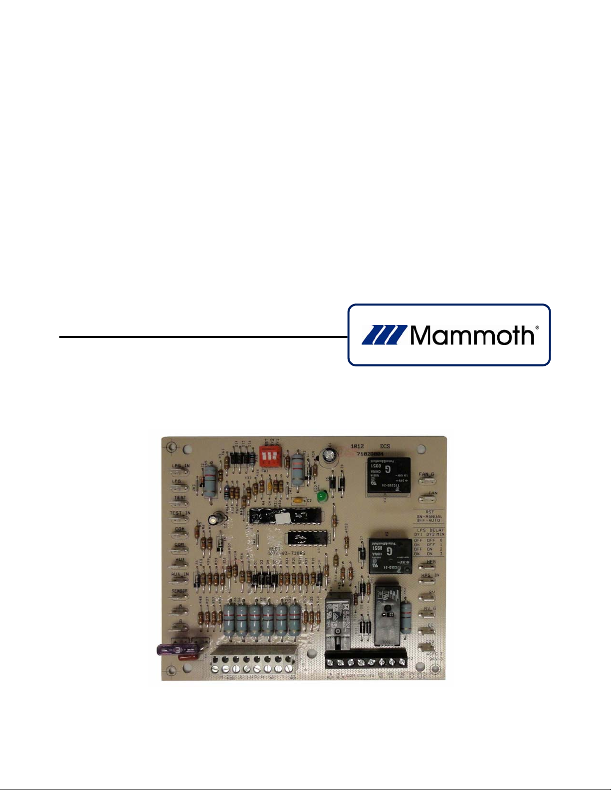
HP 5 Microprocessor Control for Mammoth
Water Source Heat Pumps
Operation and Maintenance Manual
Model: 71028004
Applies to: Single Circuit
Water-to-Water
Twin Circuit Units Without DDC Controls
MAMM‐WHSP‐IOM‐1HP5A(October2011) P/N71144918
Page 2

HP 5 Microprocessor Control
Important!
These instructions are for use by qualified
personnel specially trained and experienced in
the installation of this type of equipment and
related system components. Some states
require installation and service personnel to be
licensed. Unqualified individuals should not
attempt to interpret these instructions or install
this equipment. Read these instructions carefully
before opening (unpacking), installing and
operating this heat pump unit.
Definition
The HP 5 Microprocessor unit is designed to
operate with Mammoth’s existing series of wall
thermostats:
Manual Changeover
Auto Changeover with Night Setback,
Night Setup and Override
This unit can be used with other heat pump
thermostats, but some features may not be
available.
Features
Low and high voltage protection.
Check microprocessor at startup – self-
diagnostic
Random start time delay from 5 to 35
seconds
Compressor anti-short cycle protection
for 300 seconds (5 minutes)
Compressor, fan and reversing valve
control
Condensate overflow protection
Compressor lockout with selectable
intelligent/manual reset
LED status on the board
Lockout alarm signal to an LED in the
wall thermostat in the event of a safety
circuit fault
Fan interlock to automatically energize
the fan whenever the compressor is on
Board operable on 50 and 60 cycle
power
Emergency shutdown from a field-
supplied signal
Unoccupied (night setback and night
setup) mode from a field-supplied
signal.
Dry contact alarm signal for connection
of a fault signal to a DDC controller.
Auxiliary dry contact for tie-in of a
motorized valve when the compressor is
on (or optional compressor status)
Night heating or cooling operation from
the wall thermostat (71117203,
71117204 or 71117205 thermostat
required)
Override of the unoccupied mode from
the thermostat for 2 hours (71117204 or
7111205 thermostat required)
Low and high pressure compressor
protection
Low pressure bypass with 0, 1, 2 and 3
minute selections.
Operation
INITIAL POWER-UP: When power is applied to
the controller from unit's 24-volt transformer, a
"green” LED will be illuminated and a 120
second time delay will occur before the fan,
reversing valve and compressor are able to
operate. The controller will perform a selfdiagnostic and voltage check.
LOSS OF POWER: On a loss of 24-volt power
to the board, all the outputs are de-activated. On
return of power, a 120 second time delay will
occur before the fan, reversing valve and
compressor are able to operate. After 120
seconds, the fan, reversing valve and
compressor are able to operate after a short
time delay.
RANDOM START: A 5 to 35 second time delay
of fan, reversing valve and compressor
operation will occur each time the unit comes off
shutdown mode, unoccupied mode and low/high
voltage mode. The random start time varies
each time it is activated; for example, the time
delay may be 5 seconds, then 12, then 30, then
17, then 32, then 6, etc.
The following descriptions assume Initial
Power-up and Random Start functions have
occurred.
MAMM‐WHSP‐IOM‐1HP5A(October2011) 2
Page 3

FAN OPERATION: On a call for fan operation
from the wall thermostat “fan on" switch or from
a call for compressor operation, fan operation is
delayed for 2 seconds.
REVERSING VALVE: On a call for cooling from
the wall thermostat, the reversing valve is
energized after 4 seconds. Once the cooling
demand is satisfied, the reversing valve is held
on for 4 seconds before it is de-energized.
COMPRESSOR OPERATION: On a call for
cooling or heating from the wall thermostat,
the compressor is energized from the
compressor output terminal after 6 seconds.
Once the call for cooling or heating is satisfied,
the compressor shuts off immediately. At that
time, a 300 second (5 minute) timer begins to
prevent the compressor from re-starting even
though the wall thermostat may again call for
cooling or heating. During this 300 second
interval, the compressor will not be allowed to
restart. After the 300 second time delay elapses,
the compressor is allowed to start if the wall
thermostat calls for cooling or heating.
FAN INTERLOCK OPERATION: When
compressor operation is required, the fan is
automatically enabled 4 seconds before the
compressor, even if the wall thermostat is not
calling for fan operation. This makes sure the
fan will be on whenever the compressor is on.
SAFETY CIRCUIT OPERATION: The unit has
up to 4 safety circuits to prevent the compressor
from operating during abnormal conditions.
High Pressure Switch: If the refrigerant
pressure exceeds the high pressure setpoint, the high pressure switch opens
immediately and the unit goes into the
lockout mode
Low Pressure Switch: If the refrigerant
pressure falls below the low pressure setpoint, the low pressure switch closes
immediately and the unit goes into the
lockout mode after the amount of low
pressure bypass has been satisfied.
Optional Freezestat Switch: If the leaving
fluid temperature falls to 32°F, the freezestat
switch opens. After 10 seconds, the unit
goes into lockout mode.
Condensate Overflow Protection: If the
drain pan sensor comes in contact with
moisture for more than 30 seconds, the unit
goes into lockout mode.
LED STATUS:
ON Normal operating mode
1 Flash High pressure fault
2 Flashes Emergency shutdown mode
3 Flashes Freezestat switch
4 Flashes Condensate overflow fault
5 Flashes Low voltage fault
6 Flashes High voltage fault
7 Flashes Low pressure fault
LOCKOUT MODE: Lockout mode will occur if
any of the safety circuits are activated. In this
condition the compressor is de-energized, but
the fan operates if the wall thermostat is calling
for cooling or heating. The two lockout alarm
circuits are also enabled.
LOW AND HIGH VOLTAGE PROTECTION: If
voltage conditions are good, the unit performs a
self-diagnostic check for faults. If no faults are
identified, the “green” LED comes on with no
flashes. If the supply voltage falls below the
minimum or above the maximum, the reversing
valve, fan and compressor are de-energized.
LED lights will indicate the fault. Once the
voltage falls within an acceptable range, the unit
will restart without requiring a reset. All time
delays required for start-up of the fan,
compressor and reversing valve will take place
before the unit is re-started. The low voltage cutout is 21.6 VAC and the cut-in is 24.0 VAC. The
high voltage cut-out is 34.0 VAC and the cut-in
is 29.7 VAC. These high and low voltages are
monitored at terminals “R” and “COM”.
LOCKOUT ALARM (CIRCUIT) SIGNAL: This is
the first lockout alarm circuit. In the lockout
mode, the circuit provides a 24-volt power (+)
signal at the “LO ALM” terminal of the terminal
block which is wired to the LED on the wall
thermostat to indicate a lockout condition.
DRY CONTACTS LOCKOUT ALARM
(CIRCUIT) SIGNAL: This is the second lockout
alarm circuit. In the lockout mode, this circuit
provides a signal at the terminal block. The
signal is a set of normally open contacts at
terminals "IN ALM" and "OUT ALM" of the unit
terminal strip. The contacts close in the lockout
mode, allowing connection of a remote alarm.
RESET OF A LOCKOUT: The controller can be
selected to manual or intelligent reset of a
lockout mode through an on-board dip switch
labeled as “RST”. When a manual reset is
selected, the unit stays in lockout until it is
MAMM‐WHSP‐IOM‐1HP5A(October2011) 3
Page 4

manually reset by interrupting power or by
removing the call for mechanical heating or
cooling. Intelligent reset automatically
terminates the lockout mode 5 minutes after a
lockout condition occurs. The purpose of
intelligent reset is to allow the unit to attempt to
reset itself if the condition that caused the
original lockout corrects itself. After 3 attempts in
a 6000 second (100 minute) period after the first
lockout, the intelligent reset feature is terminated
and the unit stays in lockout until the unit is
manually reset. The number of reset attempts is
limited to protect the unit from severe damage.
UNOCCUPIED (NIGHT SETBACK AND/OR
NIGHT SETUP) MODE: This mode is functional
with the auto changeover with night setback wall
thermostat and the auto changeover with night
setback/setup and override wall thermostat only.
The unoccupied mode allows the space to be
controlled at different settings. The unoccupied
mode can be activated in two ways:
By closing the circuit between terminals
"COM" and "NS" via a field supplied switch
or time clock contacts (see Figure 1).
By supplying 24 volts to terminals "COM"
and "NS".
In the unoccupied mode, the controller ignores
the normal fan and compressor signals from the
wall thermostat and only accepts a call for
compressor operation from the night
setback/setback portion of the wall thermostat.
The signal at terminals "COM" and "NS" can be
"daisy-chained” between many units. When the
signal to terminals "COM" and “NS” is removed,
the random start timing function is activated.
NIGHT SETBACK/SETUP INPUT FROM THE
THERMOSTAT:
Once the unoccupied mode is activated and the
occupied mode operation of the fan and
compressor are terminated, the controller can
only activate compressor operation from the wall
thermostat at terminal "3" (see Figure 2). Night
setback compressor operation occurs if the
space temperature falls to 12°F below the
occupied heating set point or if the space
temperature rises to 8°F above the occupied
cooling set point. The fan will automatically
operate and cycle with the compressor due to
the fan interlock feature.
OVERRIDE: The override feature is available
with the wall thermostat and is activated by the
push button on the face of the wall thermostat
(see Figure 3). When pushed, the unit will switch
back to its normal occupied temperature set
points on the wall thermostat for 2 hours. After 2
hours, the unit will resume its unoccupied mode
operation until the unoccupied mode signal is
removed from terminals "COM" and "NS". The
push button is only operable when the unit is in
the unoccupied mode.
EMERGENCY SHUTDOWN MODE: Emergency
shutdown allows the unit to be made inoperable
via a remote signal. The emergency shutdown
mode can be activated in two ways:
By closing the circuit between terminals
"COM" and "ESD" via a field supplied set of
contacts (see Figure 4).
By supplying 24 volts to terminals "COM"
and "ESD".
In shutdown mode, the reversing valve, fan and
compressor are inoperable, the lockout alarm
circuits are activated and the green LED flashes
repeatedly 2 times (quick ON and one long
OFF). The unit does not need to be reset. The
signal at terminals "COM" and "ESD" can be
"daisy-chained" between many units. When the
signal to terminals "COM" and "ESO" is
removed, the random start timing function is
activated.
AUXILIARY DRY CONTACTS: A pair of
normally open contacts at terminals "DRC IN"
and "DRC OUT” shall close and a pair of
normally closed contacts at terminals "DRC IN"
and "DRC OUT” shall open when the
compressor is energized. This will allow
connection of 24-volt power to the normally
closed contacts to supply power to a normally
open (powered close) motorized valve when the
compressor is on.
TEST PIN JUMPER: An on-board pair of male
terminals provides for an optional mode of
operation which defeats both forms of
compressor time delays. If a hard-wired jumper
is placed across the "TEST" and "TEST IN"
terminals, the random start time delay and the
compressor's five minutes of anti-short cycle
time delay will be ignored. However, the two,
four and six second time delays on the fan,
reversing valve and compressor remain in place.
LOW PRESSURE BYPASS: The dip switches
labeled “DY1” and “DY2” allow for four different
amounts of low pressure switch bypass: zero,
one, two and 3 minutes. The low pressure
bypass timer logic occurs anytime the board
senses a low pressure switch fault.
MAMM‐WHSP‐IOM‐1HP5A(October2011) 4
Page 5
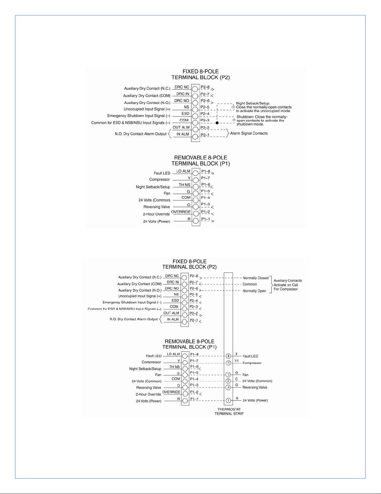
Figure 1 – Thermostat wiring with night setback/night setup and emergency shutdown
Figure 2 – Thermostat wiring with override and night setback
MAMM‐WHSP‐IOM‐1HP5A(October2011) 5
Page 6
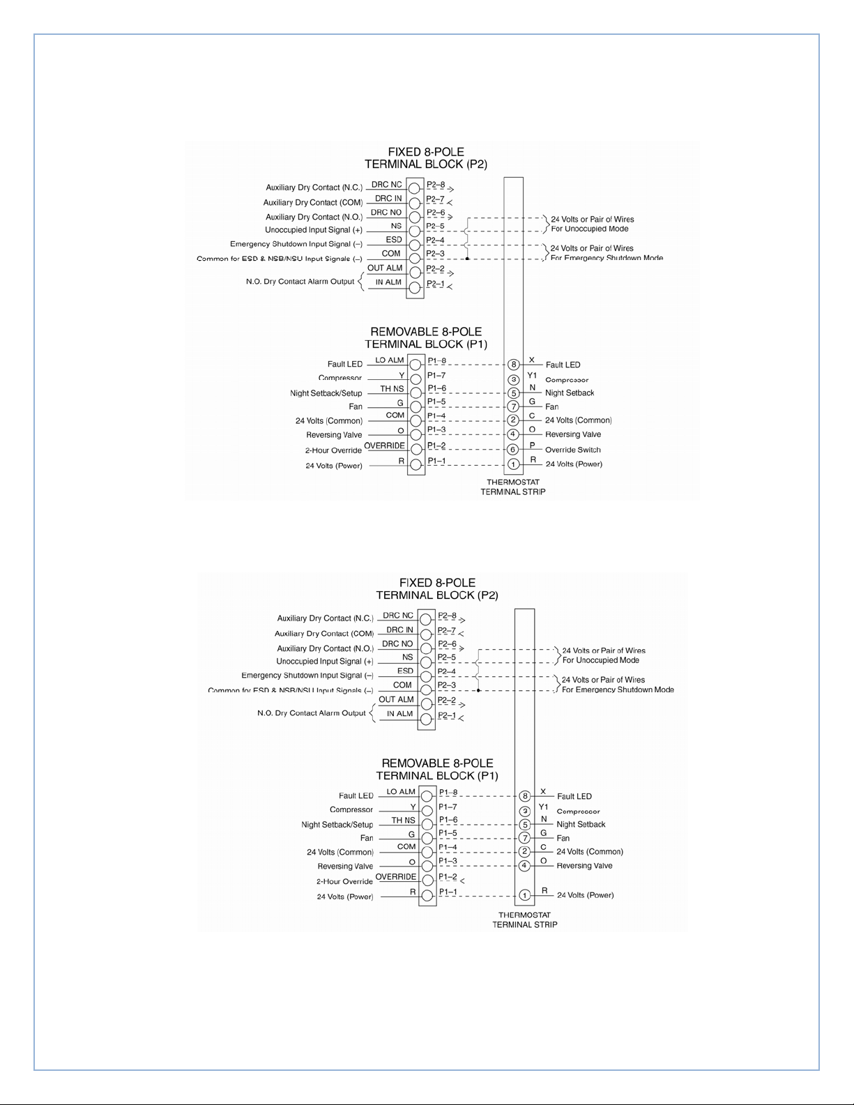
Figure 3 – Thermostat wiring emergency shutdown mode with override
Figure 4 – Thermostat wiring emergency shutdown mode without override
MAMM‐WHSP‐IOM‐1HP5A(October2011) 6
Page 7
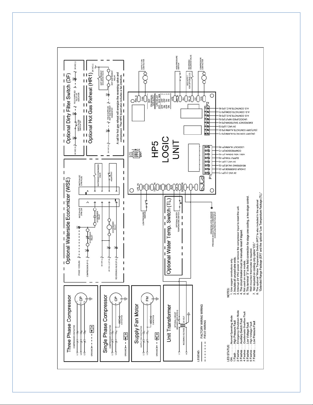
Figure 5 – Typical unit wiring
MAMM‐WHSP‐IOM‐1HP5A(October2011) 7
Page 8

Testing
FIELD TEST MODE
If the two 'TEST" quick connect terminals are
connected, there will be no random start delay,
no anti-short cycle delay, and no power to delay
present. The normal fan, reversing valve, and
compressor on delays of two, four, and six
seconds will still be present, as well as the four
second reversing off delay.
FACTORY TEST MODE
The factory mode is entered by applying the
correct combination of inputs to the control at
power up. The factory test mode operates the
control by associating
control outputs with inputs. The factory test
mode is automatically canceled after 30 seconds
after control power up, and may not be run again
until power is removed from the control.
Factory Test Mode Initiation: The control
checks the control inputs during the first 1.0
seconds after power up, looking for the factory
speedup input combination. To initiate the
factory lest mode, at some point during the first
1.0 seconds after power up, the high pressure
switch input must be active, the "SENSOR" input
must have 470 kΩ connected, the two "TEST"
quick-connect terminals connected, voltage
source must be between 22 to 29 VAC, and all
of the other inputs must be inactive.
Factory Test Mode Operation: While in the
factory test mode, the following combinations of
inputs will result in the operation of the
corresponding output conditions:
LED stays active.
“O” thermostat input active and night
setback input inactive - Reversing valve
output active.
“G” thermostat input active and emergency
shutdown input inactive - Fan output active.
“Y” thermostat input active and high
pressure switch input active - Compressor
output active.
Thermostat night setback input active and
override input inactive - Alarm output active.
[email protected]
www.mammoth-inc.com
Mammoth, Inc. has a policy of continuous product improvement and reserves the right
to change design and specifications without notice. Mammoth, Inc. is a CES Group
Company.
®
© 2011 Mammoth, Inc.
MAMM-WHSP-IOM-1HP5A
October 2011
 Loading...