


V-Cube Slim
V-Cube Slim™
Floor-by-Floor Cooling and Heat Pump System
Installation, Operation and Maintenance Manual
Sizes: 180 to 840
Model: E Series
©2011 Mammoth, Inc.
P/N 71144911

2
MAMM-VCS-IOM-1EB (October 2011)
Model Nomenclature ·················································································································· 3
Transportation and Storage ········································································································ 3
Installation ·································································································································· 4
Unit Location ······························································································································ 4
Disassembly and Assembly Instructions ···················································································· 5
Ductwork and Attenuation ·········································································································· 7
Ventilation Air ····························································································································· 7
Supply Piping ····························································································································· 8
Condensate Piping ····················································································································· 8
Cleaning and Flushing ················································································································ 9
Start-up ···································································································································· 10
Operating Limits ······················································································································· 11
Mammoth DDC Controls ·········································································································· 12
General Maintenance ··············································································································· 15
Troubleshooting ························································································································ 16
Check out sheet ······················································································································· 18
Table of Contents
3
MAMM-VCS-IOM-1EB (October 2011)
*Air handler configuration available. See MAMM-VCS-IOM-2EB for units that do not include packaged refrigeration components.
Model Nomenclature
F -180- V- H- E
Voltage BTU/hr Cooling
Unit Type Temperature Range Design Series
F = 208-230/60/3
180 = 180,000*
V = Vertical H = Standard Range
G = 460/60/3
240 = 240,000
L = Low Temperature
J = 380-415/50/3
280 = 280,000*
K = 575/60/3
310 = 310,000
350 = 350,000*
460 = 460,000
530 = 530,000*
630 = 630,000
840 = 840,000*
700 = 700,000*
830 = 830,000
Transportation and Storage
Upon receipt of the equipment, check for visible
damage. Make a notation on the shipper’s delivery
ticket before signing. If there is any evidence of rough
handling, immediately check for concealed damage. If
any damage is found, notify the carrier within 48 hours
to establish your claim and request their inspection and
a report. Then contact the Mammoth Service depart-
ment at (952) 358-6618 or info@mammoth-inc.com
for a warranty claim number.
Do not stand or transport the unit on end. In the
event that elevator transfer makes up-ended position-
ing unavoidable, absolutely ensure that the unit is in
the normal upright position for at least 24 hours before
operating.
Temporary storage at the job site must be indoors,
completely sheltered from rain, snow, etc. High or low
temperatures naturally associated with weather pat-
terns will not harm units. Excessively high tempera-
tures, 140°F (60°C) and higher, may deteriorate certain
plastic materials and cause permanent damage.
4
MAMM-VCS-IOM-1EB (October 2011)
Installation
General
1. To prevent damage, this equipment should not be
operated for supplementary heating and cooling
during the construction period.
2. Inspect the unit for any specific tagging numbers
indicated by the factory per a request from the in-
stalling contractor.
3. Check the unit nameplate for the size and voltage
rating and confirm against the plans that the unit is
being installed in the correct location.
4. Verify the installation location with the piping, sheet
metal and electrical contractors prior to installation
5. Verify all clearances are available for the unit prior
to installation.
6. Note the location and routing of water piping, con-
densate drain piping, and electrical wiring. The lo-
cations of these items are clearly marked on sub-
mittal drawings.
7. Mammoth recommends the unit be covered during
construction to protect components from dust and
other harmful material. This is critical while spray-
ing fireproofing material on bar joists, sandblasting,
spray painting and plastering.
Unit Location
Locate the unit in an area that allows for easy removal
of the filter and access panels. Leave enough space for
service personnel to perform maintenance or repair.
Provide sufficient room to make water, electrical and
duct connections. Refer to submittal drawings for
proper service clearance dimensions. Install unit in
compliance with all state and local codes.
NOTE:
Check the unit name plate for correct voltage with the
plans before installing the equipment. Make sure all
electrical ground connections are made in accordance
with local code.
IMPORTANT:
Mammoth V-Cube Slim™ units should be installed only
by qualified personnel, experienced in the installation
of this equipment and related systems. Read these
instructions carefully before unpacking, installing and
operating this unit
5
MAMM-VCS-IOM-1EB (October 2011)
Disassembly and Assembly Instructions For
V-Cube Slim™ Units
V-Cube Slim units are designed to allow for
installation in new facilities and as a retrofit for older,
obsolete equipment.
Your new V-Cube Slim will come fully assembled. In
the event building layout prohibits the unit to be moved
to its final location as a whole assembly, it will be nec-
essary to disassemble the unit into its basic sections
and reassemble it at the final location.
The standard unit consists of three sections—the elec-
trical control panel, the refrigeration/condensing section
and the blower section. Units with an optional water-
side economizer or hot/chilled water coil will have an
additional section for that coil.
The disassembly of sections requires removal of the
3/8” bolts holding them together while supporting each
section as it is being removed with rigging equipment.
Step 1 – Remove the electrical panel
Unplug the wire harness that connects the EPiC™ key-
pad and reset buttons/selector switches from the panel
door to the main electrical panel. Remove the panel
door by lifting it from its hinges and carefully set aside,
away from the unit to help prevent damage during the
remaining disassembly process.
Unplug all control wiring harnesses that run from the
main electrical panel to the compressor section. These
plugs are labeled for correct re-installation. Finally,
remove all high voltage wiring to the fan motors.
Once all electrical connections to other sections in the
unit have been removed, make sure that the electrical
panel is supported from above or below to prevent it
from falling once the bolts that connect it to the main
cabinet sections are loosened and removed.
Loosen and remove the section bolts that fasten the
main electrical panel to the main cabinet sections
(Figure 1). Set the main electrical panel aside, away
from the unit to help prevent damage during the re-
maining disassembly process.
NOTE:
Please read all disassembly instructions completely
before starting any disassembly
DANGER!
A mechanical lift is required to move or lift all sections
of a V-Cube Slim™ unit. Do not attempt to move or lift
sections without a mechanical lift. Failure to do so can
result in equipment damage, severe personal injury or
death.
DANGER!
Lifting the entire unit (blower section, coil section, etc.)
using lifting lugs, eye bolts or straps attached to the top
of the unit can result in serious damage to the unit,
personal injury or death.
Lifting the entire unit should only be done using a fork-
lift or a strapping spreader bar mechanism attached to
the base of the unit.
DANGER!
It is mandatory that all utilities (water, electric, and
communication cables to the Building Management
System) be removed prior to unit disassembly. Follow
approved lockout/tagout procedures before any disas-
sembly of the unit. Failure to do so can result in elec-
tric shock, equipment damage, severe personal injury,
or death.
NOTE:
All blower wiring is correctly phased at the factory and
must be re-wired correctly upon re-assembly for cor-
rect compressor and blower operation. Mark all wires
and pull through knockouts using care not to scrape
the insulation of the wiring when separating sections. If
the wire insulation or wire jacket is torn during the dis-
assembly/re-assembly procedure, replace the wire. Do
not use wire that is missing insulation. Control and
sensor wiring use Molex plugs for proper polarity.
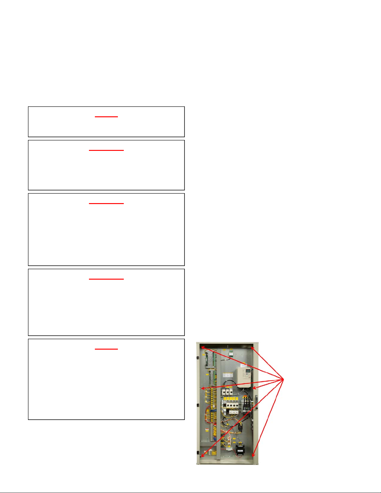
Figure 1—Electrical Control Panel Bolts
Remove the bolts used
to mount the electrical
cabinet to the main unit
sections. There are 6
bolts on the side of the
unit.
6
MAMM-VCS-IOM-1EB (October 2011)
Step 2 – Remove optional coil section
This step only applies to units with a waterside econo-
mizer or hot/chilled water coil.
Remove the bolts that connect the welded base of the
water coil section to the welded base of the main cabi-
net section.
Remove the access panels on each side of the water
coil cabinet shown in Figure 2. Inside the water coil
section, disconnect wiring to any valves and/or air sen-
sors that run to the other sections in the unit.
Once all electrical connections to the other sections in
the unit have been removed, loosen and remove the
section bolts that fasten the water coil cabinet to the
main cabinet section. Set the water coil section aside,
away from the unit to help prevent damage during the
remaining disassembly process.
Step 3 – Removing the blower cabinet
Remove the main cabinet access panels (Figure 3).
Feed any wiring for the blower motors and/or air sen-
sors passing through the refrigeration/condensing sec-
tion through the chase way into the blower cabinet.
Remove the section bolts that attach the blower cabinet
to the refrigeration/condensing section (Figure 3).
Figure 2—Optional Coil Section Removal
Remove the water pipe extensions at the Victaulic con-
nection point inside the unit. Attach lifting straps to the
motor mount plate as shown in Figure 4 and attach to a
spreader bar or forklift fork. Also attach ropes or chains
to the eye bolt on one of the motors and attach to each
end of the spreader bar or fork to level the load of the
blower section.
Use these instructions in the reverse order for assem-
bly. Replace any torn or damaged gasket with new
material. Apply a bead of silicon caulking between sec-
tions while reassembling to minimize air leaks.
For further information or assistance with these proce-
dures, contact the Mammoth Service department.
Figure 3—Removal of Blower Section Bolts
Remove Section Bolts
Remove Section Bolts
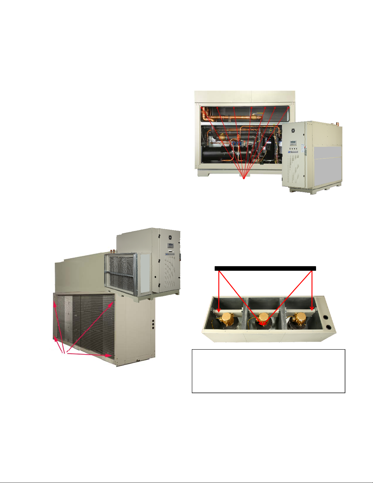
Figure 4—Lifting the Blower Section
CAUTION!
Lifting straps are to be used in lifting the blower section
only. Do not attach eye bolts to the motor mount plate
and attempt to lift the blower section. Failure to do so
can result in equipment damage and personal injury.
 Loading...