

Page 1
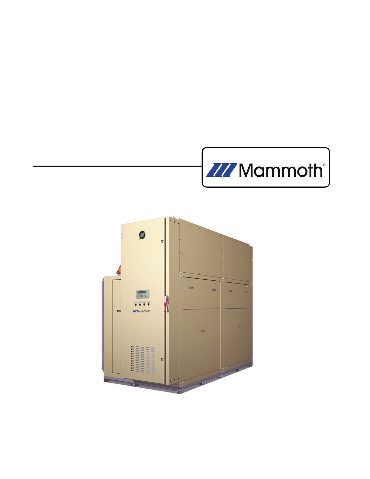
V-Cube Slim™ Split
Floor-by-Floor Cooling Systems
Installation, Operation & Maintenance Manual
Sizes: 830 and 840
Model: F-Series
MAMM-VCS-IOM-3FA (September 2013) PN 71144924
Page 2

Contents
Nomenclature .......................................................................................................................3
Introduction ...........................................................................................................................4
Warnings, Cautions and Notices ..........................................................................................4
Receiving Inspection and Storage .......................................................................................5
Disassembly and Assembly..................................................................................................6
Installation ..........................................................................................................................11
Startup ................................................................................................................................15
General Maintenance .........................................................................................................18
Troubleshooting ..................................................................................................................19
Electrical Terminal Tightening Torques ...............................................................................21
Unit Checkout Sheet ..........................................................................................................24
Mammoth V-Cube Slim Split IOM, MAMM-VCS-IOM-3FA (September 2013) 2
Page 3
Nomenclature
F 830 S H F
Voltage Size (BTUH Cooling) Unit Type Temperature Range Design Series
F = 208-230/3/60 830 = 732,000 S = Split H = Standard Range
G = 460/3/60 840 = 732,000 L = Low Temperature
J = 380/3/50
K = 575/3/60
“Mammoth” is a registered trademark of Mammoth, Inc.
©Mammoth, Inc. All rights reserved throughout the world.
Illustrations cover the general appearance of Mammoth products at the time of publication. Mammoth, Inc. reserves the right to make
changes in design and construction at any time without notice.
Introduction
This manual provides guidelines for installation, startup,
operation and maintenance of your Mammoth V-Cube
Slim unit. Also provided with your unit are submittal documents that contain detailed specifications for your unit,
including drawings and wiring schematics. If your system
is equipped with EPiC™ controls from Mammoth, full
documentation on their use is also provided.
Installation, startup and operation of this unit must follow
accepted industry practices as described in the ASHRAE
Handbook, the National Electric Code, and other applicable standards. Operate this equipment in accordance
with regulations of authorities having jurisdiction and
all applicable codes. Maintenance and service must be
performed by qualified personnel familiar with applicable
codes and regulations and experienced with this type of
equipment.
If you have additional questions about the operation or
maintenance of your Mammoth system, contact your
local Mammoth representative, or the Mammoth Service
department at (952) 358-6618 or info@mammoth-inc.
com. For assistance in locating your Mammoth representative, call 952-358-6600 or send an email to info@
mammoth-inc.com. Or, go to www.mammoth-inc.com and
click on the Find a Rep link.
Mammoth V-Cube Slim Split IOM, MAMM-VCS-IOM-3FA (September 2013) 3
Page 4
Warnings, Cautions and Notices
Warnings, cautions and notices appear at appropriate
locations throughout this manual. Your personal safety
and the proper operation of this machine depend upon
the strict observance of these precautions. Read this
manual thoroughly before operating or servicing this unit.
WARNING! Indicates a potentially hazardous
situation which, if not avoided, could result in
death or serious injury.
CAUTION! Indicates a potentially hazardous
situation which, if not avoided, could result
in minor or moderate injury. It could also be
used to alert against unsafe practices.
Receiving Inspection and Storage
When receiving equipment, check the Bill of Lading to
verify that all crates and cartons have been received.
Compare shipped-loose items received against the
list provided. Check for visible damage. If there is any
evidence of rough handling, immediately check for concealed damage. If any damage is found, refuse delivery
of the damaged item. Then contact your Mammoth Representative to place an order for a new unit or the repair
and reshipment of the damaged unit. It is encouraged
that detailed photos be taken for documentation.
This vertical unit must remain in an upright position at
all times. If this unit must be positioned horizontally during transport or rigging, it must be returned to its normal
upright position for at least 24 hours before operating.
IMPORTANT! Operating a unit after it has
been stored or transported on its side can
result in serious compressor damage which
is not covered under the equipment warranty. Make sure the unit is first returned to its
normal upright position for at least 24 hours
before operating.
Temporary storage at the job site must be indoors, completely sheltered from rain, snow, etc. High or low temperatures naturally associated with weather patterns will not
harm units. Excessively high temperatures, 140°F (60°C)
and higher, may deteriorate certain plastic materials and
cause permanent damage.
General Warnings
WARNING! Electric shock and moving equip-
ment hazard. Can cause severe injury or
death. Lock and tag out all electric power
before servicing equipment. More than one
disconnect may be required to de-energize
the unit.
CAUTION! Installation and servicing of this
equipment should only be undertaken by a
trained professional with experience working
on commercial HVAC systems. Contact your
Mammoth representative or the Mammoth Service Department for help in scheduling service.
CAUTION: Sharp edges on sheet metal, coil
surfaces and fasteners can cause personal
injury. Avoid contact and wear protective
clothing and gloves.
IMPORTANT! This product was carefully
packed and thoroughly inspected before
leaving the factory. Responsibility for its safe
delivery was assumed by the carrier upon
acceptance of the shipment. Claims for loss
or damage sustained in transit must therefore
be made upon the carrier as follows:
Visible Loss or Damage
If there is any external evidence of loss or
damage, refuse delivery of the damaged item.
Refusal of items must be noted on the freight
bill or carrier’s receipt, and signed by the carrier’s agent. Failure to adequately describe
such external evidence of loss or damage
may result in the carrier’s refusal to honor a
damage claim. The form required to file such
a claim will be supplied by the carrier.
Concealed Loss or Damage
Concealed loss or damage means loss or
damage which does not become apparent
until the product has been unpacked. The
contents may be damaged in transit due to
rough handling even though the carton may
not show external damages. When the damage is discovered upon unpacking, make a
written request for inspection by the carrier’s
agent within fifteen (15) days of the delivery
date and file a claim with the carrier.
Mammoth V-Cube Slim Split IOM, MAMM-VCS-IOM-3FA (September 2013) 4
Page 5
Disassembly and Assembly
General Guidelines
The Mammoth V Cube Slim Split is engineered to be
disassembled in the field and moved through 36” doors
into position then reassembled without breaking into the
refrigeration circuits. Only qualified personel experienced
in operation and maintenance of HVAC equipment should
perform these procedures.
WARNING! This equipment presents hazards
of electricity, rotating parts, sharp edges,
heat and weight. Failure to read and follow
these instructions can result in property damage, severe personal injury or death. This
equipment must be installed by experienced,
trained personnel only.
WARNING! A mechanical lift is required to
move or lift all sections of a V-Cube Slim™
unit. Do not attempt to move or lift sections
without a mechanical lift. Failure to do so can
result in equipment damage, severe personal
injury or death.
WARNING! Lifting the entire unit (blower
section, coil section, etc.) using lifting lugs,
eye bolts or straps attached to the top of the
unit can result in serious damage to the unit,
personal injury or death.Lifting the entire unit
should only be done using a forklift or a strapping spreader bar mechanism attached to the
base of the unit.
WARNING! All utilities (water, electric, and
communication cables) must be removed
prior to unit disassembly. Follow approved
lockout/tagout procedures before any disassembly of the unit. Failure to do so can result
in electric shock, equipment damage, severe
personal injury, or death.
IMPORTANT! All blower wiring is correctly
phased at the factory and must be re-wired
correctly upon re-assembly for correct compressor and blower operation. Mark all wires
and pull through knockouts using care not
to scrape the insulation of the wiring when
separating sections. If the wire insulation or
wire jacket is torn during the disassembly/
re-assembly procedure, replace the wire. Do
not use wire that is missing insulation. Control and sensor wiring uses Molex plugs for
proper polarity.
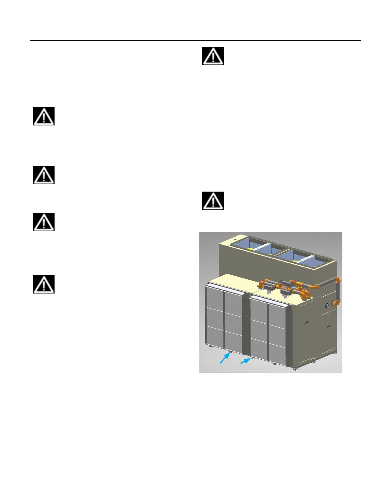
Figure 1 shows the unit as shipped from the factory. Figure 2 shows an exploded view of the unit, equipped with
coil cabinets and 2” x 4 “ filter racks. Note that the coil
cabinets and refrigeration sections are resting on welded
steel bases. These bases are an integral part of the subassemblies and must not be removed.
IMPORTANT! The welded steel bases are
integral to subassembly stability and mobility.
Do not detach!
Figure 1: Unit As Shipped
Welded steel base
Mammoth V-Cube Slim Split IOM, MAMM-VCS-IOM-3FA (September 2013) 5
Page 6
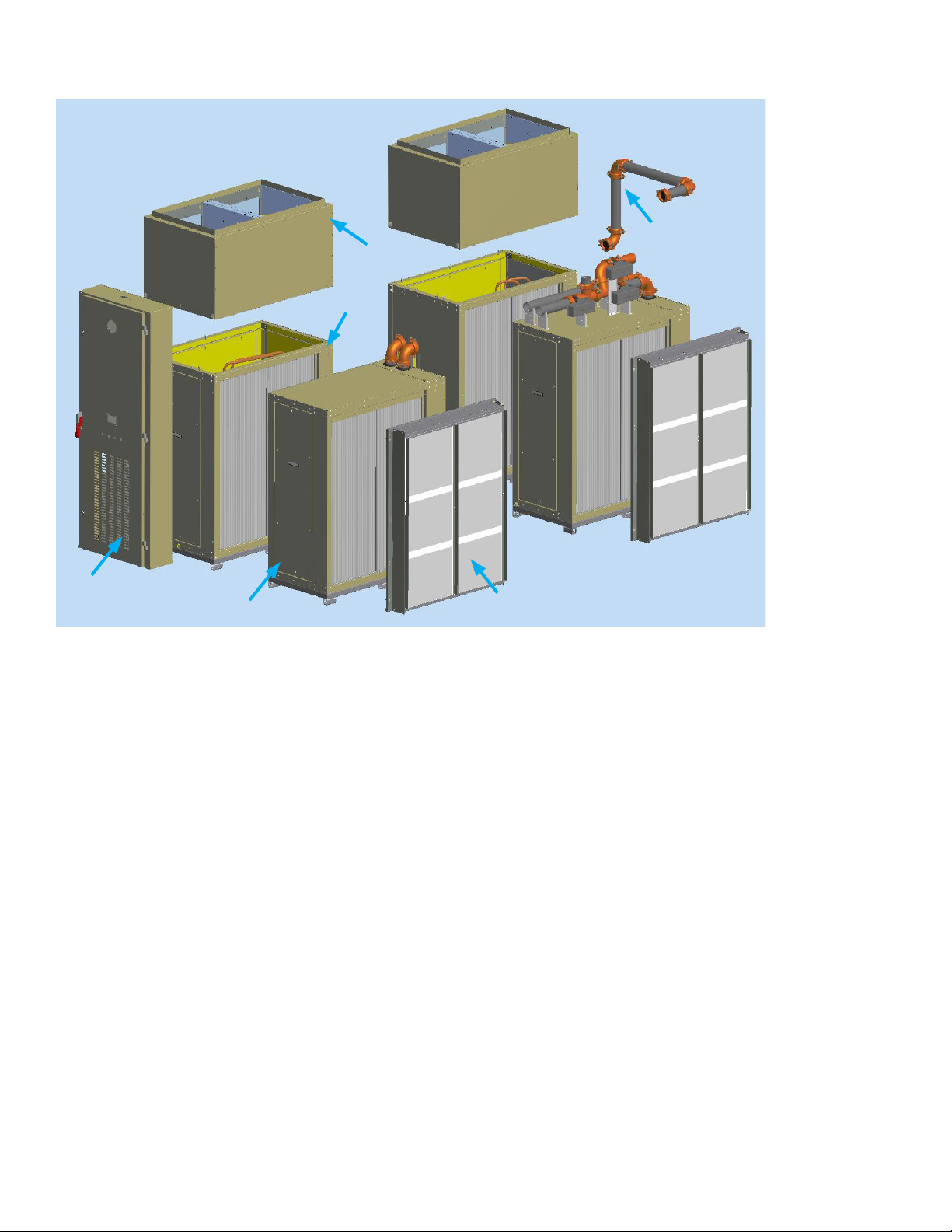
Figure 2: Exploded View
FANWALL section
Main chassis
End piping
assembly
Main electrical panel
Coil cabinet
Mechanical lifting equipment is necessary to dismantle
and relocate the V Cube Slim Split. This unit will weigh
between 4000 and 5800 pounds depending on options
and features built into the unit at the factory.
Mechanical lifting equipment is also required to remove
the sub assemblies from the main chassis. Subassemblies weigh a minimum of 205 pounds and as much as
1500 pounds each.
Wiring
NEMA does not allow quick-connect plugs for power (high
voltage) wiring. For this reason, all power wires have raw
ends and are ‘hardwired’ to terminal blocks in the unit and
Filter Rack
require handtools for removal. These power wires must
be labeled prior to removal to avoid problems.
All low voltage wires are connected using quick-connect
plugs.
Piping
All water piping is iron with grooved (Victualic®) connections.
Refrigeration circuits are copper pipe and do not require
any disassembly and reassembly.
Mammoth V-Cube Slim Split IOM, MAMM-VCS-IOM-3FA (September 2013) 6
Page 7
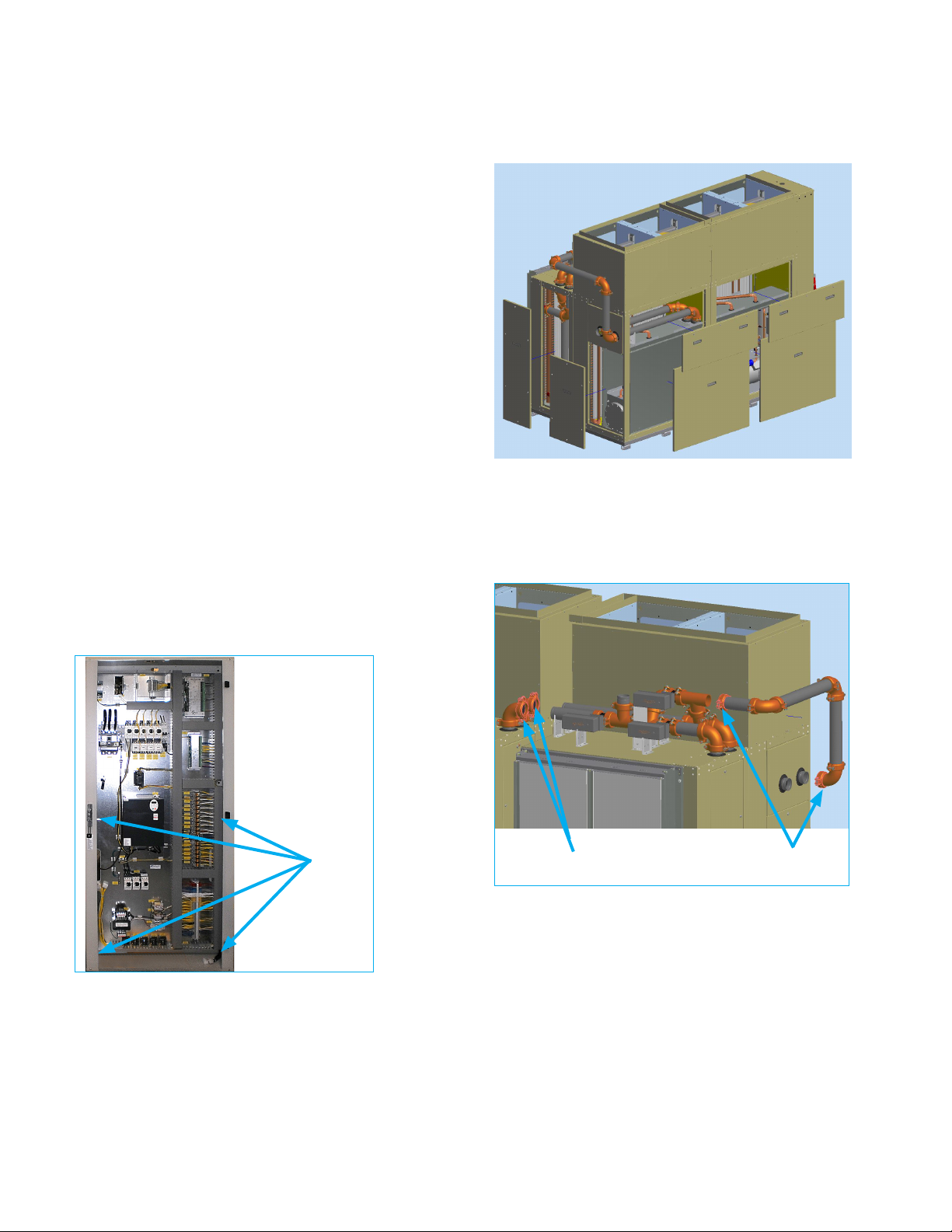
Main Electrical Panel Removal
The main electrical panel is removed as follows.
1. Unplug the wiring harness that connects the EPiC™
keypad, reset buttons and selector switches from the
panel door to the main electrical panel.
2. Remove the panel door by lifting it from its hinges.
Carefully set it away from the unit to help prevent
damage during the remaining disassembly process.
3. Unplug all control wiring harnesses that run from the
main electrical panel to the main cabinet section. All
wiring connecting the main electrical panel to the unit
passes through knockouts on the left inside corner.
These plugs are labeled for correct re-installation.
4. Disconnect all high voltage wiring to the fan motors.
5. Verify that all electrical connections to the unit from
the control panel have been disconnected.
6. Support the electrical panel from above or below to
prevent it from falling once the connecting bolts have
been removed.
7. Loosen and remove the section bolts that fasten the
main electrical panel to the main cabinet sections, as
shown in Figure 3.
8. Set the main electrical panel aside, away from the
unit to help prevent damage during the remaining disassembly process.
1. Remove all access panels and set them aside. See
Figure 4. Quarter turn, twist lock fasteners secure
most access panels.
Figure 4: Panel Removal
Unit Rear
Unit Front
2. Facing the rear side of the unit, loosen the top piping
connections between the two main sections as shown
in Figure 5. The pipes will separate as cabinet halves
are separated.
Figure 5: Rear Side Piping Disconnects
Figure 3: Main Electrical Panel Removal
Remove
mounting
bolts
Splitting Apart The Main Sections
To disassemble the unit’s two main sections into separate
halves, carry out the following procedures. To reassemble, follow these procedures in reverse.
Top piping
connections
End piping assembly
connections
3. Loosen the piping connections on either end of the
end piping assembly, as shown in Figure 5. Then
remove the end piping assembly and set it aside. (If
the end piping assembly is not already installed, it is
packed inside the unit for field assembly.)
4. Facing the front of the unit, loosen the piping connections between the two main sections as shown in Figure 6. The pipe connections will separate as cabinet
halves are separated.
Mammoth V-Cube Slim Split IOM, MAMM-VCS-IOM-3FA (September 2013) 7
Page 8
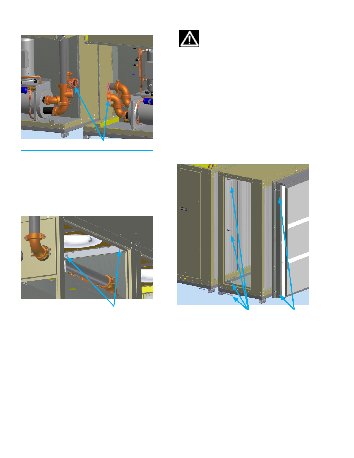
Figure 6: Front Side Piping Disconnects
Piping connections
IMPORTANT! Filter rack mounting bolts are
a specific length so as to not contact the coil
behind the bulkhead. If any are lost, replacement bolts must be the same length.
2. If still in place, remove the coil cabinet inner access
panel from the side of the cabinet.
3. Remove the six fasteners (three on each side) connecting the sides of the coil cabinet to the main chassis.
4. Remove the nuts and bolts (two sets, one on each
end) connecting the coil cabinet to the main chassis
at the welded steel base.
5. The coil cabinet can now be separated from the main
chassis. Each coil cabinet will weigh at least 300
pounds.
5. Remove the nuts and bolts connecting the two main
sections at the welded steel base.
6. Remove the connecting bolts from the upper access
panel location as shown in Figure 7.
7. The unit should now come apart in two halves. Each
side will weigh at least 1000 pounds.
Figure 7: Upper Access Panel Conecting Bolts
Upper access
panel bolts
Figure 8: Filter Rack and Coil Cabinet Removal
Coil cabinet
fasteners
Filter rack
fasteners
Filter Rack and Coil Cabinet Removal
Once the unit has been split apart into separate halves,
the coil cabinet and filter rack can be removed from the
FANWALL Section Removal
The FANWALL cells come off in pairs; each pair weighing
roughly 600 pounds. They are removed as follows.
main chassis, as follows. See Figure 8 for fastener locations.
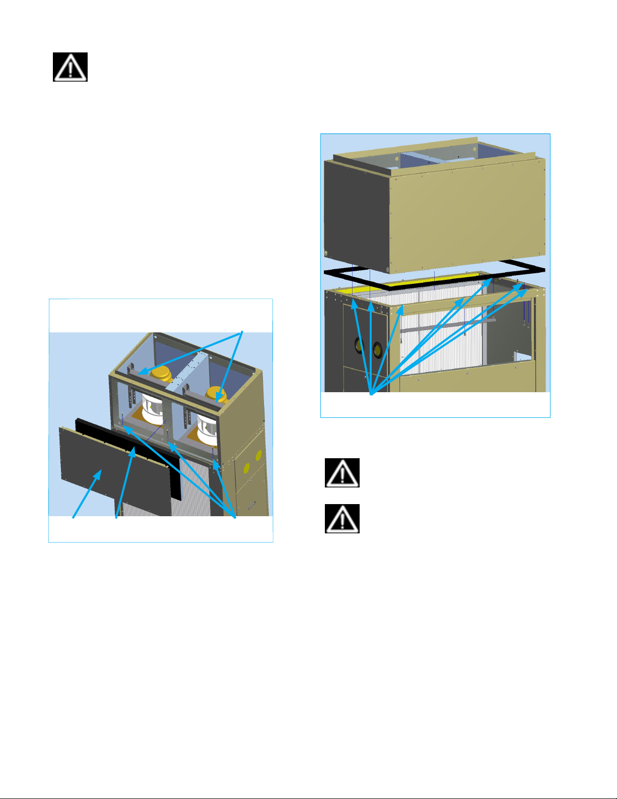
1. Loop lifting straps around both motor mount frames
as shown in Figure 9 and then to a spreader bar or to
1. Remove the filter rack from the coil cabinet by screwtwo forklift forks.
ing out the fasteners from the four corners of the
rack.
Mammoth V-Cube Slim Split IOM, MAMM-VCS-IOM-3FA (September 2013) 8
Page 9
CAUTION! DO NOT lift the fan cells by the
motor eye bolts or by attaching eye bolts to
the motor mount plates. This may result in
personal injury, equipment damage or motor/
wheel misalignment.
6. Remove the access panel from the back of the base
cabinet section as shown in Figure 9.
7. Remove the seven fasteners (three on the front, two
on each end) connecting the FANWALL section to the
main chassis as shown in Figure 10.
2. As a safety precaution, take up the slack in the lifting
straps before removing any connecting bolts from the
section.
3. Remove the screws from the access panel on the
front of the FANWALL section, then remove the
panel. See Figure 9.
4. Remove the screws from the sound attenuation
panel, then remove the panel. See Figure 10.
5. Remove the three fasteners that attach the front, coil
side of the FANWALL section to the base as shown in
Figure 9.
Figure 9: FANWALL Removal From Front
Loop lifting straps
around the motor
mount frames
Figure 10: FANWALL Removal from Rear
Section
fasteners
Access
panel
Sound attenuation panel
Section
fasteners
8. Carefully lift the FANWALL section off the base with
the attached lifting straps.
CAUTION! This method of lifting may be
imbalanced. Use care to avoid personal injury
or damage to the FANWALL section.
IMPORTANT! The gasket between the FANWALL section and the main chassis must be
replaced before reassembling the section.
Failure to do so may cause air leakage and
poor unit performance.
Mammoth V-Cube Slim Split IOM, MAMM-VCS-IOM-3FA (September 2013) 9
Page 10
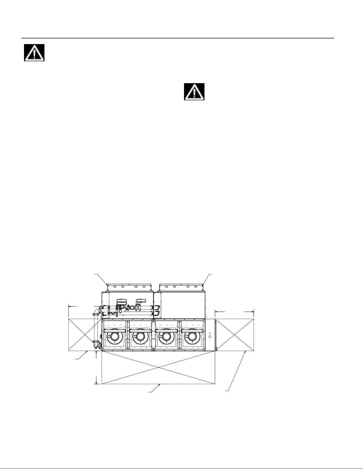
Installation
SERVICE CLEARANCE
WARNING! The installer must determine
and follow all applicable codes and regulations. This equipment presents hazards of
electricity, rotating parts, sharp edges, heat
and weight. Failure to read and follow these
instructions can result in property damage,
severe personal injury or death. This equipment must be installed by experienced,
trained personnel only.
General
To prevent damage, this equipment should not be operated for supplementary heating and cooling during the
construction period.
Inspect the unit for any specific tagging numbers indicated by the factory per a request from the installing contractor.
Check the unit nameplate for the size and voltage rating and confirm against the plans that the unit is being
installed in the correct location.
Verify the installation location with the piping, sheet metal
and electrical contractors prior to installation
Verify all clearances are available for the unit prior to
installation.
Note the location and routing of water piping, condensate
drain piping, and electrical wiring. The locations of these
items are clearly marked on the unit submittal drawings.
Mammoth recommends the unit be covered during construction to protect components from dust and other
harmful material. This is critical while spraying fireproofing
material on bar joists, sandblasting, spray painting and
plastering.
IMPORTANT! Check the unit name plate for
correct voltage with the plans before installing the equipment. Make sure all electrical
connections are made in accordance with
national (NEC) and local codes.
Location and Clearances
This equipment is designed for indoor installation only.
Sheltered locations such as attics, garages, etc., generally will not provide sufficient protection against extremes
in temperature and/or humidity, and equipment performance, reliability, and service life may be adversely
affected.
Units should be mounted on a flat, level floor or on a
code-compliant housekeeping pad. An antivibration pad
or mat is recommended between the bottom of the unit
and the surface beneath it.
Figure 11 and Figure 12 show recommended minimum
clearances. Local building and/or electrical codes may
require additional clearance. Refer to local codes.
If the unit has an open or non-ducted return, provide
adequate clearance to the return air opening to ensure
proper air flow.
Figure 11: Clearances - Unit With Waterside Economizer
FILTER ACCESS
36.0 [914]
SHELL AND TUBE
SERVICE CLEARANCE
]
4
1
[9
.0
6
3
FILTER ACCESS
42.0 [1067]
SERVICE CLEARANCE
Mammoth V-Cube Slim Split IOM, MAMM-VCS-IOM-3FA (September 2013) 10
Page 11
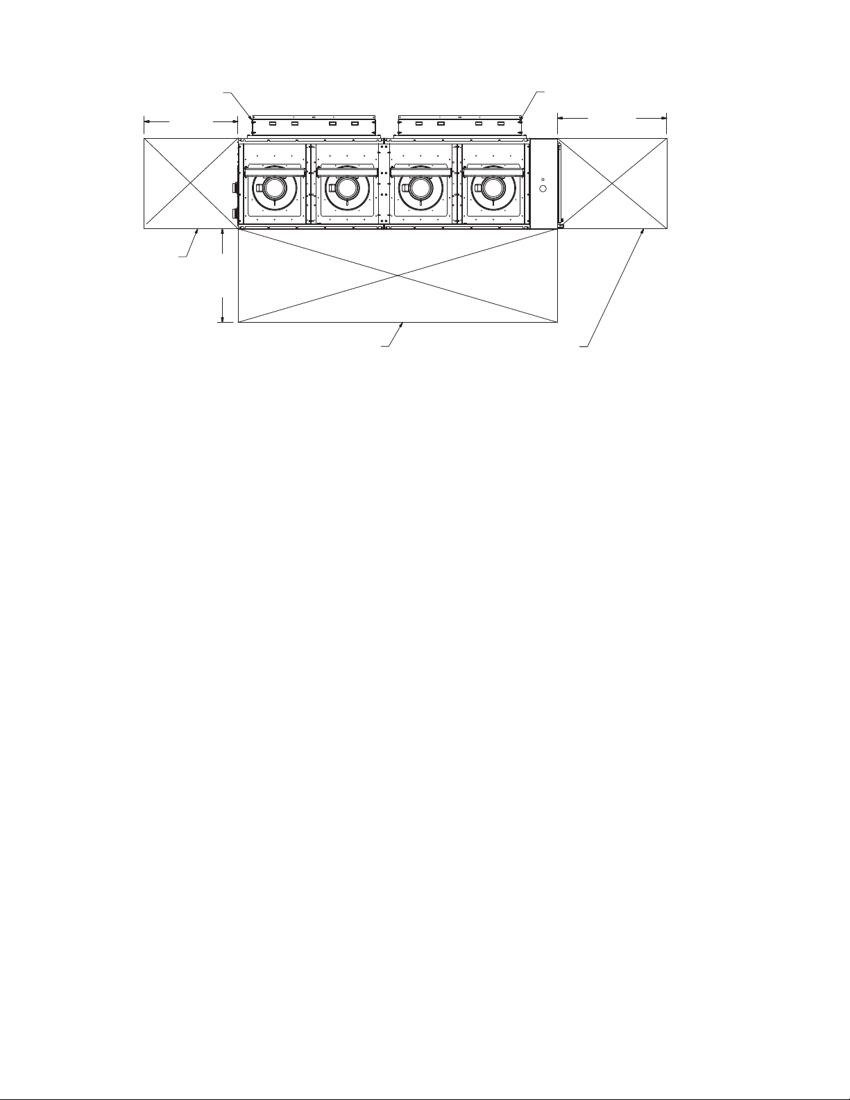
Figure 12: Clearances - Units Without Waterside Economizer
FILTER ACCESS
FILTER ACCESS
36.0 [914]
SERVICE CLEARANCE
]
4
1
9
[
0
.
6
3
SERVICE CLEARANCE
Ductwork and Attenuation
Discharge ductwork is normally used with the V-Cube
Slim™. Return air ductwork may also be required.
All ductwork should conform to industry standards of
good practice as described in the ASHRAE Systems
Guide.
The discharge duct system will normally consist of a flexible connector at the unit connection, a transition piece
to the full duct size, a short run of duct, and elbow with
vanes, and a trunk duct teeing into a branch duct with
discharge diffuses. The transition piece must not have
angles totaling more than 30° or severe reduction in airflow performance can result.
Do not connect the full duct size to the unit. Use a transition piece sized according to the discharge collar on the
unit to get to the full duct size. With metal duct material,
the sides of the elbow and entire branch duct should be
internally lined with acoustic fibrous insulation for sound
attenuation. Glass fiber duct board material is more
absorbing and may permit omission of the canvas connector.
Return air ductwork (if used) should be connected to the
unit using the filter section flange.
Ventilation Air
Outside air may be required for ventilation. Refer to local
codes. The temperature of the ventilation air must be
controlled so that the mixture of outside air and return
air entering the unit is within application limits. It is recommended that the ventilation air inlet be closed during
unoccupied periods (i.e. night setback).
The ventilation air system is typically a separate building
subsystem with distribution ductwork. Simple introduction
of the outside air into each return air plenum chamber
42.0 [1067]
SERVICE CLEARANCE
reasonably close to the unit air inlet is recommended.
Do not duct outside air directly to the unit inlet. Provide
sufficient distance for the thorough mixing of outside and
return air.
Supply Piping
NOTE: Read all Supply Piping instructions before proceeding.
All units should be connected to supply and return piping
in a two-pipe, reverse-return configuration. A reversereturn system is inherently self-balancing and requires
only trim balancing where multiple quantities of heat
pumps with different flow and pressure drop characteristics exist in the same loop. Check for proper water
balance by measuring differential temperature reading
across the water connections.
Avoid dissimilar metal fittings as they may corrode. If the
use of dissimilar metals cannot be avoided, use dielectric
isolation at that connection point
Supply and return shutoff valves are recommended at
each unit. A flow control device to limit fluid flow through
the unit should be connected to the water outlet.
No unit should be connected to the supply and return piping until the water system has been cleaned and flushed
completely. After the cleaning and flushing has taken
place, the initial connection should have all valves wide
open in preparation for the water system flushing.
Condensate Piping
Condensate piping can be steel, copper, or PVC. Each
unit includes a minimum of two stainless steel condensate connections; one in each coil cabinet section.
The condensate disposal piping must be trapped. The
piping must be pitched away from the heat pump not less
than ¼” per foot. The unit is supplied with a 1-¼” male
Mammoth V-Cube Slim Split IOM, MAMM-VCS-IOM-3FA (September 2013) 11
Page 12
pipe fitting to accommodate the condensate drain connection.
10. Flush the system for at least two hours, or longer if
required, until the drain water is clear and clean.
Do not locate any point in the drain system above the
drain connection of any unit.
The condensate piping system must be vented at its
highest point.
Cleaning and Flushing
Before building water is connected to the unit, the building water system must be flushed clean of particulate
contaminants. Follow the procedures described in this
section.
IMPORTANT! Performance of WSHP units
relies upon a building water supply filtered of
any particulate and chemical contaminants.
Before building water is connected to the unit,
the building water system must be flushed
clean of particulate contaminants. The building water system is also required to have a
neutral PH balance.
Failure to bring the building water system into
compliance with these requirements, verifiable by recorded documentation, will void unit
warranties.
11. Shut off the supplemental heater (if applicable) and
the circulator pump.
12. Open all drains and vents to completely drain down
the system. .
13. Refill the system with clean water.
14. Test the water using litmus paper for acidity and treat
as required to leave the water slightly alkaline (pH 7.5
to 8.5).
15. The specified percentage of antifreeze may also be
added at this time. Use commercial grade antifreeze
designed for HVAC systems only. Do not use automotive grade antifreeze.
16. Once the system has been filled with clean water and
antifreeze (if used), precaution should be taken to
protect the system from dirty water conditions.
IMPORTANT! Dirty water will result in system-wide performance degradation and solids
may clog valves, strainers, flow regulators,
etc. Additionally, the heat exchangers may
become clogged which reduces compressor
service life or causes premature failure.
1. Open all air vents.
2. Fill the system at the city water makeup connection.
3. After filling, close all air vents.
4. Open the pressure reducing valve.
5. Check air vents in sequence to bleed off any trapped
air, providing circulation through all components of
the system.
6. Check and repair any leaks in the piping.
7. Start the main circulator with the pressure reducing
valve open.
8. Open the drains at the lowest point(s) in the system
for the initial flush and blow down, making sure city
water fill valves are set to make up water at the same
rate.
9. Check the pressure gauge at the pump suction and
manually adjust the makeup to hold the same positive steady pressure both before and after opening
the drain valves.
17. Supply power to all motors and start the circulation
pumps.
18. After full flow has been established through all components, including the heat exchanger (regardless of
season), and after air has been vented and loop temperatures stabilized, each of the units will be ready
for check, test, startup, and water balancing.
Electrical Connections
CAUTION! Verify that the unit label voltage
matches building power before connecting
power wires to the unit. Do not apply power to
the unit until all installation work is completed.
Wiring to the unit is routed through the electrical knockout
in the top of the main electrical panel. See . The incoming
power connection is made at the power voltage termi-
nal block and the ground wire is connected to the unit’s
grounding lug. Control wiring enters the unit through the
small knockout on top of the main electrical panel.
Mammoth V-Cube Slim Split IOM, MAMM-VCS-IOM-3FA (September 2013) 12
Page 13
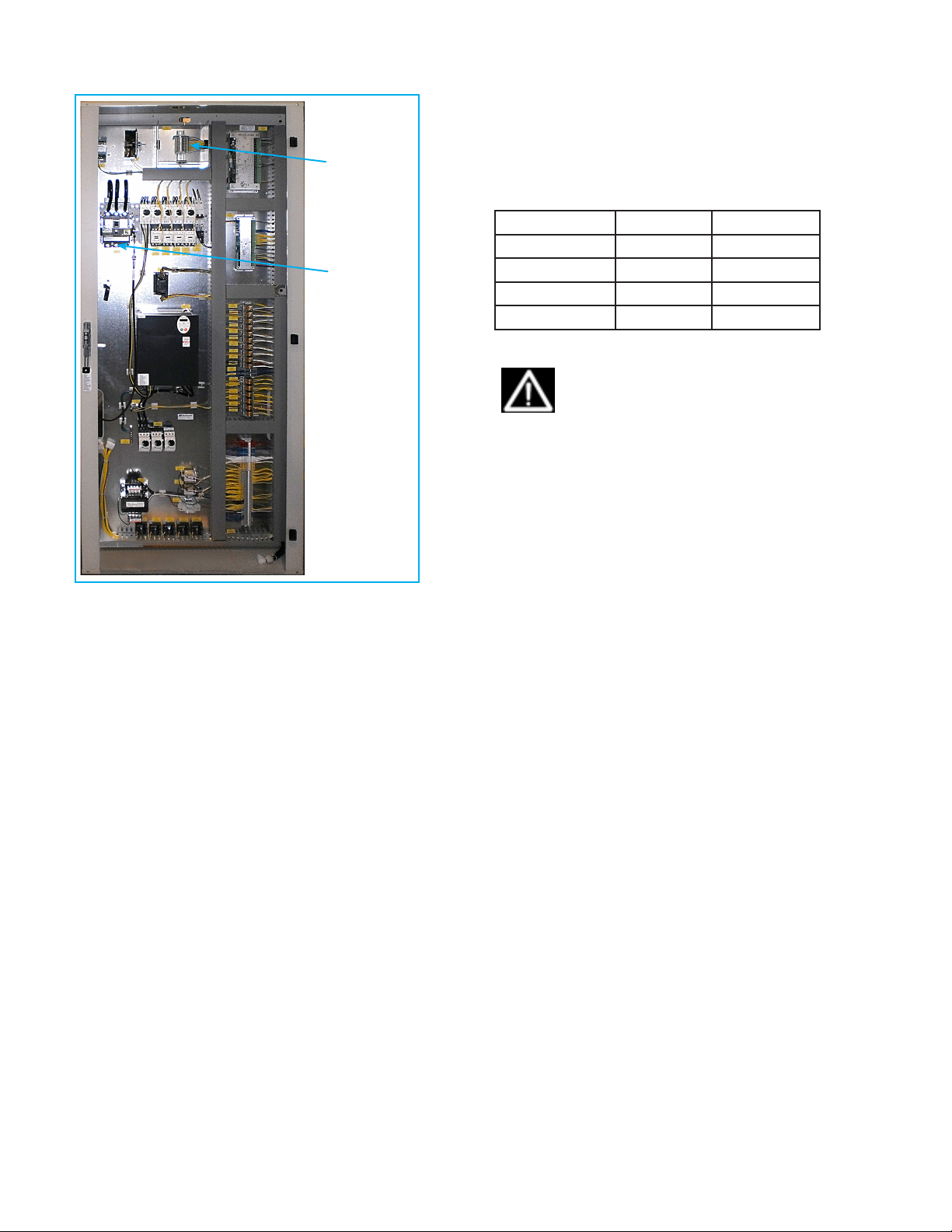
Figure 13: Electrical Connection Points
Field
control
wiring
Power
wiring
Operating Voltage
Incoming power supply must comply with the data in
Table 1. Unit operation outside of the Min/Max range is
not recommended and will result in premature component
failure.
Table 1: Operating voltages
Minimum Maximum
208-230/60/3 197 volts 253 volts
460/60/3 414 volts 506 volts
380-415/50/3 342 volts 418 volts
575/60/3 515 volts 632 volts
.
IMPORTANT! Units operating with over- or
under-voltage conditions for extended periods
of time will experience premature component
failure. Three-phase system imbalance should
not exceed 2%.
Mammoth V-Cube Slim Split IOM, MAMM-VCS-IOM-3FA (September 2013) 13
Page 14
Startup
The following should be used as a guide for a comprehensive commissioning and startup procedure which is
required before placing your Mammoth unit into service.
IMPORTANT! The commissioning and startup
procedures described in this document must
be carried out prior to placing this unit into
service. Failure to follow these procedures
could result in improper or dangerous operation and/or void the equipment warranty.
CAUTION! Installation, startup and servicing
of this equipment should only be undertaken
by trained professionals with experience
working on commercial HVAC systems. Contact your Mammoth representative or the
Mammoth Service Department for help in
scheduling service.
Startup Report Form
A startup report form is zip-tied to the inside of the main
control panel. In addition to carrying out the procedures
described in this guide, it should be filled out, signed and
returned to Mammoth as part of the warranty process for
your system. See the warranty documents included with
your unit for additional information.
Prior to Startup
Before requesting unit startup, please verify all of the following.
• The main power supply is connected to the unit disconnect and electrical power is available to run the
unit.
WARNING! Electric shock and moving equipment hazard. Can cause severe injury or
death. Lock and tag out all electric power
before carrying out these procedures. More
than one disconnect may be required to deenergize the unit..
Electrical
Electrical Terminals
Tighten all electrical terminals per the torque value listed
on the connector. Electrical terminals are located within
the main unit control panel. Where no torque value is
given, use the tightening torques provided in this manual.
See “Electrical Terminal Tightening Torques” on page
19.
WARNING! Loose electrical terminals can
lead to erratic unit operation and arcing which
may cause fires. Tighten all electrical terminals before unit startup. Be careful not to
over-tighten to avoid stripping out threads..
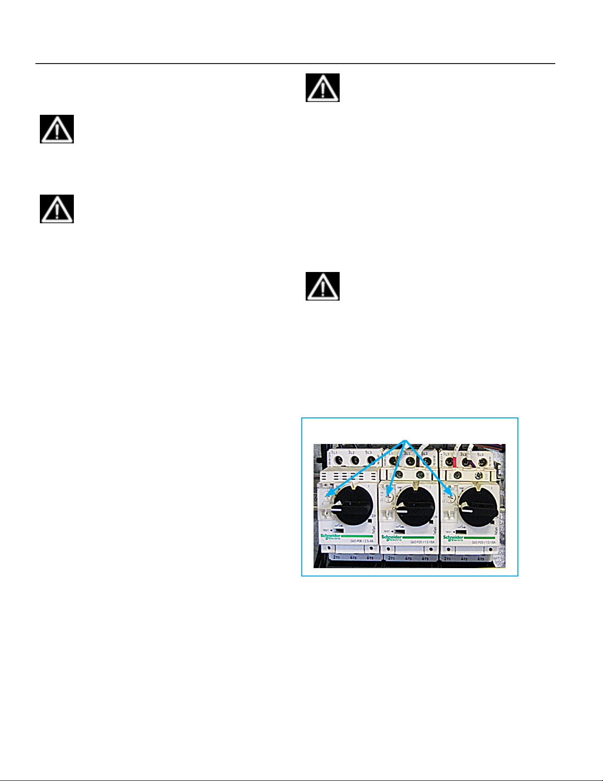
Motor Protector Settings
Before startup, adjust the overload setting on all motor
protectors as follows. They are located within the unit
electrical panel. See Figure 14.
Figure 14: Motor Protectors
Adjust motor protector amp settings to match electrical
schematics or motor nameplates
• Drain lines are connected to the condensate connections. See “Condensate drain” on page 17.
• The controls contractor has been notified of the
requested start-up date and is confirmed to attend.
• The duct system is complete enough to allow for
operation.
• All air filters have been installed.
• All water systems, if applicable, have been fully
installed, tested and will be operable.
Startup: Power Off
Verify that the system on/off and/or standby switch is in
the off or standby position. Then carry out the following
procedures.
Mammoth V-Cube Slim Split IOM, MAMM-VCS-IOM-3FA (September 2013) 14
1. Switch to the off position all motor protectors.
2. For motors and pumps, adjust the setting to match
the amps (FLA) listed on the motor nameplate.
3. For compressors and VFDs, adjust the setting as
indicated on the electrical wiring diagram provided
with your unit.
Page 15

Control Settings
• Verify that all control jumper positions, time delay
relay settings, baud rates and control temperatures
and/or pressure settings match those indicated on
the electrical wiring diagram, as applicable. Refer to
the wiring schematics provided with your unit for locations and settings.
Verify that high and low static pressure safety settings
match those indicated on the electrical wiring diagram.
They are typically set at 3.5 inches w.c. each. Record the
values on the Startup Report form.
Refrigerant Piping
Mammoth V-Cube Slim units with DX cooling are shipped
fully charged with refrigerant from the factory. No piping
connections are needed and no field charging is required
prior to operation of the system. Check the following prior
to startup:
• Verify that all pressure lines are free from the compressors – i.e., not contacting or rubbing against
them – to prevent damage from vibration and friction.
Pressure line coils should have a distance between
each coil of at least one inch.
• Verify that all pipe clamps have the rubber lining
intact and are secure.
• Verify that all compressor service valves are open.
Startup: Power On
With the main power control panel door closed, switch on
the main power to the unit. Then carry out the following
procedures.
WARNING! Electric shock and moving equipment hazard. Can cause severe injury or
death. Use extreme caution when inspecting
or servicing equipment with electrical power
supplied to the unit. Per OSHA 29 CFR
1910.333 (c)(2): “Only qualified persons may
work on electric circuit parts or equipment
that have not been de-energized. Such persons shall be capable of working safely on
energized circuits and shall be familiar with
the proper use of special precautionary techniques, personal protective equipment, insulating and shielding materials, and insulated
tools.”
Electrical
Supply Power
• Verify that the measured supply voltage matches the
rated voltage on the unit nameplate. The nameplate
is located on the electrical panel door. Record voltages on the startup form.
Motor Rotation
• Verify that all fans, blowers and pumps are rotating
in the correct direction. This can be accomplished
by shutting off the motors individually, using each
motor’s overload protector shut-off switch, then
observing the direction of rotation as you start them
back up.
• Check for proper rotation of each compressor using
a phase rotation meter. Also verify that the unit phase
monitor is set correctly as indicated on the electrical
wiring diagram provided with your unit.
Mammoth V-Cube Slim Split IOM, MAMM-VCS-IOM-3FA (September 2013) 15
Page 16
Blowers and Fans
2. Turn the unit system switch to the on position.
Switch the motor protectors for the supply air fans to the
On position (see page 6 for motor protector locations).
Turn the system switch to the On position, then carry out
the following checks:
• Verify that the unit controller is calling for the unit to
operate. Consult the controls documentation provided
with your unit to trouble shoot any problems.
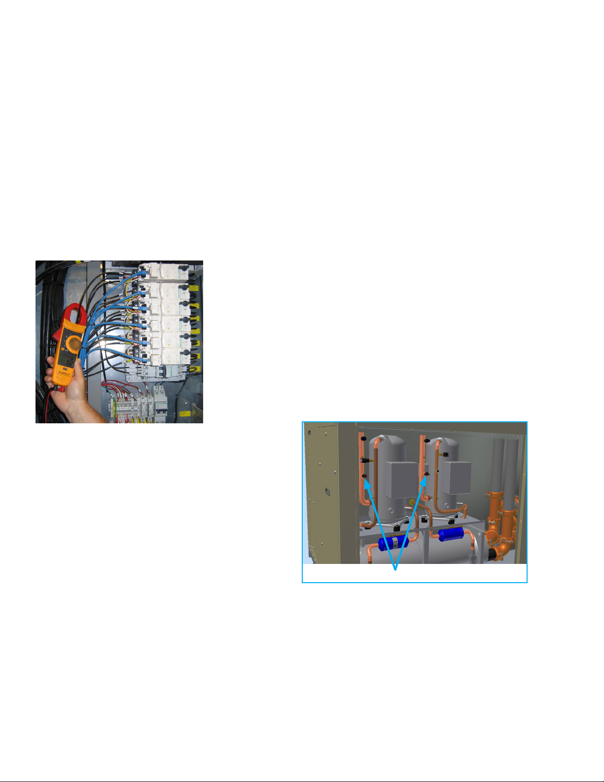
• Measure the amp draw of all blowers and fan motors
and record them on the startup report form. Verify
that they do not exceed the FLA listed on the motor
nameplate. Amp draw can be checked using an amp
draw meter clamped around the motor wires leading
into the motor protectors for each motor. See Figure
15.
Figure 15: Amp Draw Check
3. Verify that the liquid sub-cooling is between 10 and
12 degrees F (8 to 10 degrees F for shell and tube or
flat plate condensers).
4. Verify that the super heat is within 12 to 18 degrees F
at the compressor.
Repeat each step above for all additional compressor circuits to be started.
Geothermal Units Only
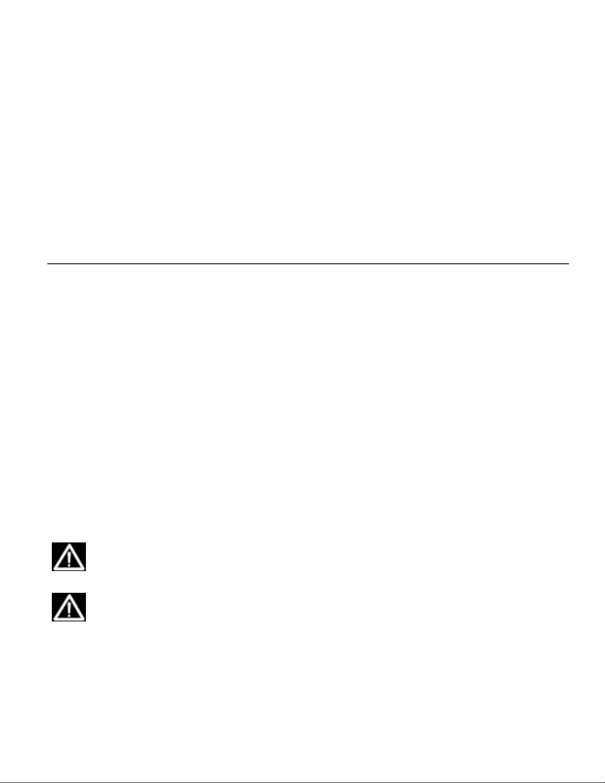
For geothermal units only, verify that the low-pressure
switches installed on the suction line of each comporessor are all labeled “40 to 50 PSI.” This is accomplished as
follows:
1. Remove the front cover from the main chassis on
both halves of the V-Cube Slim Split unit.
2. The low pressure switches are inserted into the compressor suction piping about halfway up the overall
height of each compressor. See Figure 16
3. Do not attempt to turn or rotate the switch.
4. View the label on each of the switches. It should read
“40 to 50 PSI.” If it does not, contact your Mammoth
representative to replace the switch.
• Verify that the parameter settings are correct on the
supply and return/exhaust fan VFDs, as applicable.
Refer to the parameter settings that are detailed on
the wiring diagrams provided with your Mammoth
unit. Refer to the instruction manual for the VFD for
information on how to navigate through the parameter
menus.
DX Cooling Startup
A reasonable cooling load must be available to perform
a proper cooling startup. With a cooling load available,
carry out the following procedure on each circuit:
1. Install refrigeration gauges on the compressor circuit
to be started.
Note: Due to tight quarters, an inspection mirror or smart
phone photo may be necessary to view the pressure
range label on the switch.
Figure 16: Pressure Switches
Pressure switches (one per compressor)
Mammoth V-Cube Slim Split IOM, MAMM-VCS-IOM-3FA (September 2013) 16
Page 17
Chilled Water, Hot Water and Steam Coils
Startup
Visually check the coils and system piping for proper
installation and any signs of leakage. Repair as needed.
Check motorized valves and linkages for the following
points of operation.
Controls Startup
For controls startup procedures, see the EPIC® Sequence
of Controls documentation that is included in the packet
of information that is zip-tied to the inside of the main
control panel.
Final System Check
• The motor should be free to run through its complete
stroke.
• The linkage should work freely without binding.
• The valve must close off tightly at the bottom of its
stroke.
General Maintenance
Normal maintenance on any V-Cube Slim™ unit includes
but may not be limited to the following:
Air filter changes
Air filters must be replaced a minimum of two times per
year. A good standard to follow is at the beginning of the
cooling season and the beginning of the heating season.
In certain environments, more frequent filter changes may
be required. For new installations, it is recommended that
the air filters be checked every 60 days and changed as
required until a regular interval can be established. An air
filter needs to be replaced if no light can be seen through
it when it is held up to a light.
Condensate drain
The condensate drain and drain pan should be checked
on an annual basis to verify positive drainage and
cleaned or flushed as necessary.
• Verify that controller read out values are equal to
actual gauge or temperature readings, as applicable.
• Install all refrigeration fitting caps, etc., that were
removed during the startup procedure.
• Check the refrigeration system for leaks.
• Clean up all debris.
Electrical terminals are located within the main unit control panel. Tighten all terminals per the torque value listed
on the connector. Where no torque value is given, use
the tightening torques provided in this manual. See “Electrical Terminal Tightening Torques” on page 19.
On all units with electric heat, check the condition of
contactors and wiring at the beginning of each heating
season.
Data recording
Recording current draw of blower motors at regular intervals is recommended to verify their condition. Recording
differences in water temperature and air temperature at
regular intervals can help identify any performance degradation. Annual comparison of the data will aid in determining the overall condition and operation of the unit.
Nuisance trips and/or lockouts
Electrical
Check the tightness of all electrical terminals twice each
year. Retighten as needed.
WARNING! Loose electrical terminals can
lead to erratic unit operation and arcing which
may cause fires.
WARNING! Electric shock and moving equipment hazard. Can cause severe injury or
death. Lock and tag out all electric power
before carrying out these procedures. More
than one disconnect may be required to deenergize the unit.
Mammoth V-Cube Slim Split IOM, MAMM-VCS-IOM-3FA (September 2013) 17
Occasional trips and/or lockouts are generally caused
by water or airflow restrictions. When a trip or lockout
occurs, check the water flow rate, incoming water temperature, airflow rates and incoming air temperature. Take
corrective action necessary to enable unit operation.
Parts and Service Support
Mammoth brand products are serviced by Authorized Service Providers. For service support, contact your Mammoth representative. Parts for Mammoth brand products
are also available by contacting your local representative.
For assistance locating your Mammoth representative,
visit www.mammoth-inc.com.
Page 18
Troubleshooting
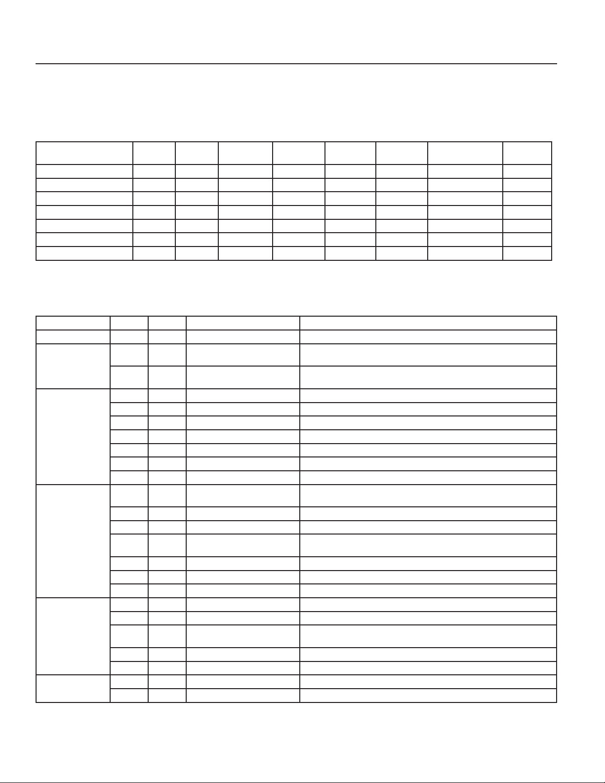
The charts in this section provide general guidelines on
troubleshooting problems with your V-Cube Slim unit. If
Service assistance is required contact Mammoth Service
at (952) 358-6618. For additional help diagnosing prob-
lems or servicing the unit, contact your local Mammoth
representative. For assistance locating your Mammoth
representative, call 952-358-6600 or e-mail info@mammoth-inc.com.
Table 2: Refrigeration system troubleshooting*
Symptom
Undercharged system Low Low Low High Low Low Low Low Pressure
Overcharged system pressure High High High Normal Low Normal Normal High Pressure
Low air flow in cooling Low Low Low Low or Normal Low Low Low Low Temp
Low water flow in cooling High High High High Low Low High High Pressure
High air flow incooling Low High Normal High Low Low Normal High Pressure
High water flow in cooling Low Low Low Low HIgh Normal Low Low Temp
TVX restricted High Low Normal or low High High Low Low
* Referenced values for your unit are recorded on the factory run test sheet. This sheet is part of the unit documents provided with your unit.
They are located within the main electrical panel.
Head
Pressure
Suction
Pressure
Compressor
Amp Draw
Super Heat Subcooling
Air Temp
Differential
Water Loop Temp
Differential
Safety
Lockout
Figure 17: Performance troubleshooting
Problem Heating Cooling Possible Cause Solution
Insufficient Capacity X X Dirty Filter Replace or clean
Not cooling or heating
properly
Unit doesn’t operate in
cooling
High head pressure X Reduced or no air flow in heating Check for dirty air filter and clean or replace. Check fan motor operation and airflow
Low suction pressure X Reduced water flow in heating Check pump operation or valve operation/setting. Check water flow adjust to proper flow rate
Low discharge air
temperature in heating
X X Reduced or no air flow Check for dirty air filter and clean or replace, Check fan motor operation and airflow
X X Leaky duct work Check supply and return air temperatures at the unit and at distant duct registers: If
X X Low refrigerant charge Check superheat and subcooling
X X Restricted metering device Check superheat and subcooling– replace
X Defective reversing valve Perform RV touch test
X X Thermostat improperly located Check location and for air drafts behind stat
X X Unit undersized Recheck loads & sizing. Check sensible, cooling load and heat pump capacity
X X Scaling in waterside heat exchanger Perform scaling check and clean if necessary
X X Inlet water to hot or cold Check load, loop sizing, loop backfill, ground moisture
X Reduced or no water flow in cooling Check pump operation or valve operation/setting. Check water flow; adjust to proper flow rate
X Inlet water to hot Check load, loop sizing, loop backfill, ground moisture
X Air temperature out of range in
heating
X Scaling in waterside heat exchanger Perform scaling check and clean if necessary
X X Unit overcharged Check superheat and subcooling
X X Non-condensable in system Vacuum system, reweigh in charge
X Water temperature out of range Bring water temp within design parameters
X Reduced air flow in cooling Check for dirty air filter and clean or replace. Check fan motor operation and airflow
X Air temperature out of range Too much cold vent air? Bring entering air temp within design parameters
X X Insufficient charge Check for refrigerant leaks
X Too high of air flow Check fan motor speed selection and airflow
X Poor performance See insufficient capacity
restriction. External static too high? Check static vs. blower table
significantly different, duct leaks are present
restrictions. External static too high? Check static vs. blower table
Bring return air temp within design parameters
restrictions. External static too high? Check static vs. blower table
Mammoth V-Cube Slim Split IOM, MAMM-VCS-IOM-3FA (September 2013) 18
Page 19
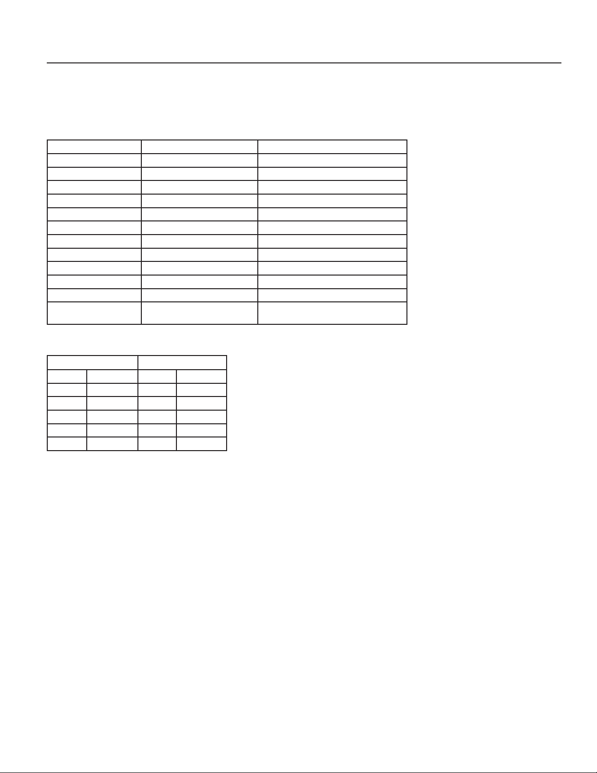
Electrical Terminal Tightening Torques
The following tables provide tightening torques, as recommended by the component manufacturer, for many of
the electrical components provided on Mammoth units.
value instead. Where no torque value is given or provided
here, use the torques provided in the tables at the end of
this section, which are taken from UL Standard 486A.
If a torque value is provided on the component, use that
Table 3: Telemecanique manual motor starters, controllers, and protectors
Device Model Tightening Torque
Motor Starter GV2ME 15 lb-in (1.7 N•m)
Motor Starter GV2P 15 lb-in (1.7 N•m)
Motor Starter LS1D30, LS1D303 15 lb-in (1.7 N•m)
Motor Starter LS1D32, LS1DT32, LS1D323 15 lb-in (1.7 N•m)
Motor Starter GV3ME06 through ME20 15 lb-in (1.7 N•m)
Motor Starter GV3ME25 through ME63 44 lb-in (5 N•m)
Trip Module GV2AU 12 lb-in (1.4 N•m) max
Trip Module GV2AS 12 lb-in (1.4 N•m) max
Auxiliary Contact GVAN, GVAD 12 lb-in (1.4 N•m) max
Auxiliary Contact GV2AD, GV2 AM11 12 lb-in (1.4 N•m) max
Auxiliary Contact GV2AE 12 lb-in (1.4 N•m) max
Terminal Block GV2G05 and GV1G09 Connector: 20 lb-in (2.2 N•m)
Screw clamp: 15 lb-in (1.7 N•m)
Table 4: Altivar 212 variable speed drives
Maximum Wire Size Tightening Torque
2
mm
6 10 1.3 11.5
16 6 2.5 22
25 3 4.5 40
50 1/0 24 212
150 300 kcmils 41 363
AWG N-m lb-in
Mammoth V-Cube Slim Split IOM, MAMM-VCS-IOM-3FA (September 2013) 19
Page 20
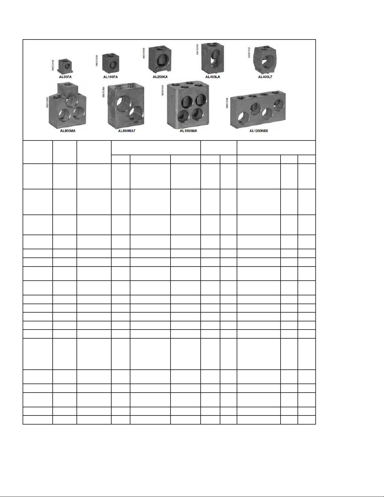
Table 5: Square D Molded Case Circuit Breakers – Mechanical lug kit wire ranges and torques
Lug Kit
Lugs
Per Kit
Circuit
Breaker
Wires Per Lug and Wire Ranges
Wires Domestic Metric Lb-in. N•m Wire* Lb-in. N•m
AL50FA 3 FA, FH, FI 1 #14–#4 Cu or
#12–#4 Al
2.5–25 mm2
4–25 mm
Lug Mounting
Screw Torque
40 4.5 Cu #14–#4 STR/
2
Wire Binding Screw Torque
35
SOL
Al #12–#4 STR
35
15
4.0
4.0
1.7
Al #12–#10 SOL
AL100FA4 3 FC 1 #14–#3 Cu or
#12–#1 Al
AL100FA 3 FA, FH, FI 1 #14–1/0 Cu or
#12–1/0 Al
2.5–50 mm2
4–50 mm
AL100TF 3 FA, FH 1 #12–#3 Cu 50 5.7 Cu #12–#3 STR
65 7.3 Cu #14–#3 STR
40 4.5 Cu #14–1/0 STR
2
Cu #14–#8 SOL
Al #8–#1 STR
Al #12–#10 SOL
Al #12–1/0 STR
Al #12–#10 SOL
Cu #12–#10 SOL
65
7.3
65
7.3
65
7.3
65
7.3
80
9.0
80
9.0
40
4.5
50 505.6
5.6
AL250KA 3 KA, KH, KC, KI 1 #6–#350 kcmil 25–185 mm280 9.0 250 28.2
AL250KI 3 KC, KI 1 1/0–#350 kcmil 50–185 mm280 9.0 250 28.2
AL400LA 1 Q4, LA, LH 1 2#0–#600 kcmil or
#1–#250 kcmil»
AL800MA7 1 MA, MH 2 #500–#750 kcmil 240–300
50–300 mm2
50–120 mm
2
mm
180 20.0 300 33.9
2
180 20.0 300 33.9
AL900MA 1 MA, MH 3 3/0–#500 kcmil 95–240 mm2180 20.0 300 33.9
AL1000MA 1 MA, MH 4 1/0–#350 kcmil 50–185 mm2180 20.0 300 33.9
AL1200NE6 1 NA, NC 4 3/0–#600 kcmil 95–300 mm2250 28.2 330 37.3
AL2500PA 2 PAF, PHF, PCF 1 3/0–#750 kcmil 95–300 mm2840 550
CU30FA4 3 FC 1 #14–#10 Cu N/A N/A #14–#10 STR/SOL 35 4.0
CU100FA 3 FA, FH, FI 1 #14–#1 Cu 2.5–50 mm
2
50 5.7 Cu #3–#1 STR
Cu #8 STR/SOL
Cu #14–#10 STR/
Cu #6–#4 STR
50
45
40
35
5.7
5.1
4.5
4.0
SOL
CU100TF 3 FA, FH 1 #12–#3 Cu 50 5.7 Cu #12–#3 STR
Cu #12–#10 SOL
CU250KA 3 KA, KH, KC, KI 1 #6–#250 MCM Cu 16–20 mm
CU400LA 1 Q4, LA, LH 2 #1–#600 MCM Cu
#1–#250 MCM Cu
50–300 mm2
50–120 mm
2
80 9.0 250 22.6
180 20.0 300 33.9
2
50 505.7
5.7
CU1000MA 1 MA, MH 3 3/0–#500 MCM Cu 95–240 mm2300 33.9 300 33.9
CU1200NE6 1 NA, NC 4 3/0–#600 MCM Cu 95–300 mm2250 28.2 330 37.3
* STR = Stranded, SOL = Solid
Table 6: UL 486A tightening torques for electrical terminals, pound-inch (N-m)
Mammoth V-Cube Slim Split IOM, MAMM-VCS-IOM-3FA (September 2013) 20
Page 21
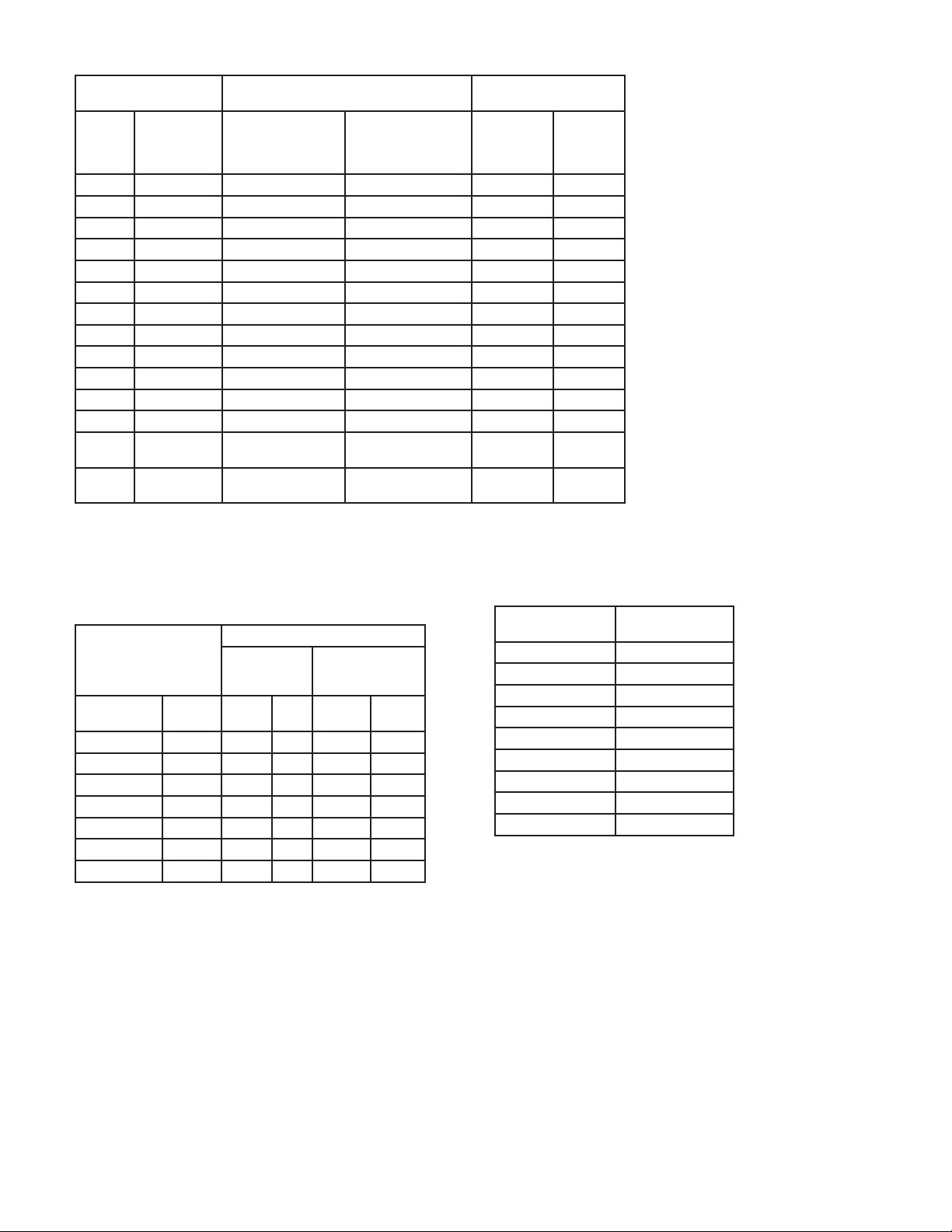
Conductor size installed in
connector
AWG or
kcmil
30 – 10 (0.05 – 5.3) 20 (2.3) 35 (4.0) 80 (9.0) 75 (8.5)
8 -8.4 25 (2.8) 40 (4.5) 80 (9.0) 75 (8.5)
6 – 4 (13.3 – 21.2) 35 (4.0) 45 (5.1) 165 (18.6) 110 (12.4)
3 -26.7 35 (4.0) 50 (5.6) 275 (31.1) 150 (16.9)
2 -33.6 40 (4.5) 50 (5.6) 275 (31.1) 150 (16.9)
1 -42.4 – 50 (5.6) 275 (31.1) 150 (16.9)
1/0 – 2/0 (53.5 – 67.4) – 50 (5.6) 385 (43.5) 180 (20.3)
3/0 – 4/0 (85.0 – 107.2) – 50 (5.6) 500 (56.5) 250 (28.2)
250 – 350 (127 – 177) – 50 (5.6) 650 (73.4) 325 (36.7)
400 -203 – 50 (5.6) 825 (93.2) 325 (36.7)
500 -253 – 50 (5.6) 825 (93.2) 375 (42.4)
600 – 750 (304 – 380) – 50 (5.6) 1000 (113.0) 375 (42.4)
800 –
1000
1250 –
2000
*For values of slot width or length not corresponding to those specified, select the largest torque value associated with
the conductor size. Slot width is the nominal design value. Slot length is measured at the bottom of the slot.
(mm2)
(406 – 508) – 50 (5.6) 1100 (124.3) 500 (56.5)
(635 – 1016) – – 1100 (124.3) 600 (67.8)
Slotted head No. 10 or larger*
Slot width to
3/64 inch (1.2 mm) or
slot length to 1/4 inch
Slot width – over
3/4 inch (1.2 mm) or
slot length over 1/4
inch
Hexagonal head - external
drive socket wrench
Split-bolt
connectors
Other
connectors
Table 7: UL 486A tightening torques for slotted head
screws smaller than No. 10 intended for use with No. 8
AWG or smaller conductors
Slot width of screw
b
Slot length of screw
Inch (mm)
Less than 5/32 (4) 7 (0.79) 9 (1.0)
5/32 (4) 7 (0.79) 12 (1.4)
3/16 (4.8) 7 (0.79) 12 (1.4)
7/32 (5.6) 7 (0.79) 12 (1.4)
1/4 (6.4) 9 (1.0) 12 (1.4)
9/32 (7.1) 15 (1.7)
Above 9/32 (7.1) 20 (2.3)
a Slot width is the nominal design value.
b For slot lengths of intermediate values, select torques pertaining to next
shorter slot length. Also see note to Table 7.4 for screws with multiple
tightening means. Slot length is to be measured at the bottom of the slot.
Smaller than
3/64 inch (1.2
mm)
pound-
inch
(N-m)
a
3/64 inch (1.2 mm)
and larger
pound-
inch
(N-m)
Table 8: UL 486A tightening torques for socket head
screws
Socket Size Across
Flats -- Inches
1/8 45
5/32 100
3/16 120
7/32 150
1/4 200
5/16 275
3/8 375
1/2 500
9/16 600
Tightening Torque,
Pound Inches
Mammoth V-Cube Slim Split IOM, MAMM-VCS-IOM-3FA (September 2013) 21
Page 22
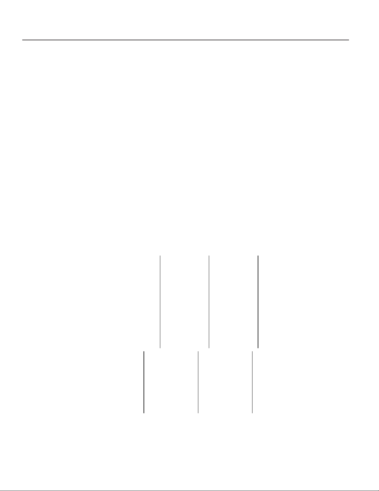
Unit Checkout Sheet
V-Cube Slim Unit Checkout Sheet
Customer Data
Customer Name ________________________________________ Date _________________________________________
Address ________________________________________________________________________________________________
Phone ________________________________________________ Unit Number___________________________________
Unit Nameplate Data
Make _______________________ Model Number ________________________ Serial Number _______________________
Compressor(s):
# 1: RLA_______ LRA _______ Refrig, Charge (oz.) _______ # 2: RLA_______ LRA _______ Refrig, Charge (oz.) ______
# 3: RLA_______ LRA _______ Refrig, Charge (oz.) _______ # 4: RLA_______ LRA _______ Refrig, Charge (oz.) ______
Blower Motor(s):
# 1: FLA (or NPA)________ HP __________ # 2: FLA (or NPA)________ HP __________
# 3: FLA (or NPA)________ HP __________ # 4: FLA (or NPA)________ HP __________
Maximum Fuse Size (Amps) __________ _____________ Minimum Circuit Ampacity (Amps) __________________
Operating Conditions
Unit Conditions Cooling Mode Heating Mode Measured At:
Entering Air Temperature _____________ _____________ _________________________________
Leaving Air Temperature _____________ _____________ _________________________________
Entering Fluid Temperature _____________ _____________ n/a
Leaving Fluid Temperature _____________ _____________ n/a
Fluid Flow (gpm) _____________ _____________ n/a
Fluid Side Pressure Drop _____________ _____________ n/a
Compressor # 1 # 2 # 3 # 4
Mode Cooling Heating Cooling Heating Cooling Heating Cooling Heating
Suction Pressure (psig) _______ _______ _______ _______ _______ _______ _______ _______
Discharge Pressure (psig) _______ _______ _______ _______ _______ _______ _______ _______
Suction Temp (at compressor) _______ _______ _______ _______ _______ _______ _______ _______
Discharge Temp (at compressor) _______ _______ _______ _______ _______ _______ _______ _______
Suction Superheat (at compressor) _______ _______ _______ _______ _______ _______ _______ _______
Liquid Line Leaving Condenser Temp _______ _______ _______ _______ _______ _______ _______ _______
Liquid Subcooling _______ _______ _______ _______ _______ _______ _______ _______
# 1 # 2 # 3 # 4 Volts/Amps
L1 L2 L3 L1 L2 L3 L1 L2 L3 L1 L2 L3 Phase
Compressor Volts _____ _____ _____ _____ _____ _____ _____ _____ _____ _____ _____ _____
Compressor Amps _____ _____ _____ _____ _____ _____ _____ _____ _____ _____ _____ _____
Blower Volts _____ _____ _____ _____ _____ _____ _____ _____ _____ _____ _____ _____
Blower Amps _____ _____ _____ _____ _____ _____ _____ _____ _____ _____ _____ _____
Mammoth V-Cube Slim Split IOM, MAMM-VCS-IOM-3FA (September 2013) 22
Page 23

Mammoth V-Cube Slim Split IOM, MAMM-VCS-IOM-3FA (September 2013) 23
Page 24

www.mammoth-inc.com
Mammoth, Inc. has a policy of continuous improvement and reserves the right
to change design and specifications without notice.
© 2013 Mammoth, Inc.
MAMM-SVC-IOM-3FA
September 2013
 Loading...