

Page 1
VHC
!
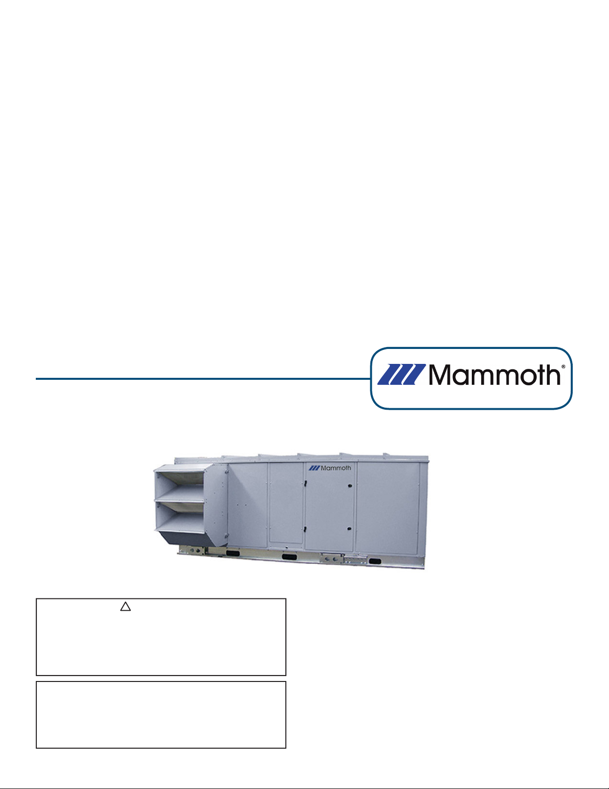
Energy Recovery Ventilators with Enthalpy Wheels and
Integrated Heating and Cooling
Installation, Operation and Maintenance
Capacity: 800 to 5,500 cfm
Model: VHC-36, VHC-42, VHC-50
WARNING
Improper installation, adjustment, alteration, service or
maintenance can cause injury or death. Read the installation, operation and maintenance instructions in this
appendix thoroughly before installing or servicing this
equipment.
IMPORTANT
The use of this appendix is specically intended for a
qualied installation and service agency. A qualied installation and service agency must perform all installation and
service of these appliances.
MAMM-VHC-IOM-1A (January 2013)
Page 2

Table of Contents
Table of Contents .................................................................................................................................................................2
Nomenclature .......................................................................................................................................................................3
Safety Considerations ..........................................................................................................................................................4
General Information ..............................................................................................................................................................4
Unit Application Limitations ............................................................................................................................................4
Installation ............................................................................................................................................................................4
Unit Location Requirements ...........................................................................................................................................4
Roofcurbs Supplied by Mammoth (External Applications Only) ..................................................................................... 5
Roofcurbs Supplied by Others .......................................................................................................................................6
Rigging and Placing the Unit ..........................................................................................................................................6
Field Fabricated Ductwork ..............................................................................................................................................6
Hood Installation .............................................................................................................................................................7
Access Panels ................................................................................................................................................................ 7
Internal Packaging ..........................................................................................................................................................7
Electrical Connections .................................................................................................................................................... 8
Water Source Heat Pump (WSHP) Water Piping and Connections .............................................................................10
Condensate Drain Trap ................................................................................................................................................10
Start-up ...............................................................................................................................................................................11
Pre Start-up Procedure ................................................................................................................................................11
Start-up Procedure .......................................................................................................................................................11
Optional Controls and Accessory Sequence and Interlocks ........................................................................................12
Frost Control .................................................................................................................................................................13
Airow Balancing .......................................................................................................................................................... 14
Service................................................................................................................................................................................15
Quarterly Maintenance .................................................................................................................................................15
Annual Maintenance .....................................................................................................................................................15
Coils .............................................................................................................................................................................15
Testing and Replacement of the Damper Actuator ......................................................................................................16
Motor and Blower Removal – Down, Side and End Supply/Exhaust ...........................................................................16
Motor and Blower Service – Down, Side and End Supply/Exhaust .............................................................................16
Belt Tension Adjustment ..............................................................................................................................................17
Plenum Fan and Motor Removal ..................................................................................................................................17
Plenum Fan and Motor Service .................................................................................................................................... 18
Cassette Removal ........................................................................................................................................................18
Cassette Service ..........................................................................................................................................................19
Appendix A: Service Clearance Dimensions ...................................................................................................................... 20
Appendix B: Hood Installation ............................................................................................................................................21
Appendix C: Rigging Drawing.............................................................................................................................................22
Appendix D: Equipment Data .............................................................................................................................................23
Appendix E: Electrical Data ................................................................................................................................................ 24
Appendix F: Terminal Control Diagrams ............................................................................................................................27
Appendix G: Standard Field Wiring (FW) Terminals ..........................................................................................................30
Appendix H: VHC-36, 42 and 50 Start-up Report and Checklist ........................................................................................ 31
Appendix I: Troubleshooting ...............................................................................................................................................35
Appendix J: Electric Heating Coil and Controls Information ............................................................................................... 37
Appendix K: Water Line Field Mounted Options and Accessories .....................................................................................39
Appendix L: Enthalpy Wheel Pressure Drop vs. Flow Formulae and Curves ...................................................................47
Manufacturer reserves the right to discontinue or change specications or designs without notice or obligation.
MAMM-VHC-IOM-1A (JANUARY 2013)
2
Page 3

Nomenclature
VHC-XX
Ventilator
with heating
and cooling
Nominal wheel
diameter
– 36
– 42
– 50
©Mammoth Inc. 2012. All rights reserved throughout the world.
Illustrations cover the general appearance of Mammoth products at the time of publication and Mammoth reserves the
right to make changes in design and construction at any time without notice.
™® The following are trademarks or registered trademarks of their respective companies: Tefzel from DuPont.
MAMM-VHC-IOM-1A (JANUARY 2013)
3
Page 4
Safety Considerations
!
!
!
Warning, Caution and Important notes appear throughout
this manual in specic and appropriate locations to alert Installing Contractors and maintenance or service personnel
of potential safety hazards, possible equipment damage or
to alert personnel of special procedures or instructions that
must be followed as outlined below.
WARNING
Identies an instruction which, if not followed, might cause
serious personal injuries including possibility of death.
CAUTION
Identies an instruction which, if not followed, might severely damage the unit, its components, the assembly or
nal installation.
General Information
These ventilators can provide 100% outdoor air ventilation or, depending on options selected, varying amounts of
recirculation between the exhaust and supply airstreams.
The VHCs use an enthalpy wheel for total energy recovery which provides superior efciency in hot and humid
climates. These models are also effective in cold climates
and use various types of frost control or defrost to ensure
IMPORTANT
Indicates supplementary information needed to fully complete an instruction or installation.
Hazards may exist within this equipment because it contains electrical and numerous moving components. Only
qualied service personnel should install or service this
equipment. Untrained personnel may perform basic maintenance such as maintaining lters. Observe precautions
marked in literature and on labels attached to the unit. Follow all safety codes.
WARNING
Disconnect the main power switch to the unit before performing service or maintenance. Electric shock can cause
personal injury or death.
proper operation when the outside temperatures are extremely low. Units intended for rooftop installations must
be installed on a factory or eld supplied roofcurb. This
manual contains information on optional components that
may or may not be included with this unit. Refer to the submittals for options that pertain to this unit.
Unit Application Limitations
WARNING
Mammoth equipment is not designed to be used for temporary heating, cooling and/or ventilation during construction.
Using Mammoth units for temporary ventilation during
construction constitutes a violation of Mammoth warranty
terms which indicate that the unit warranty would be void
“…if equipment is misapplied or if any alterations are made
to the basic design or operating requirements as listed
on the original order and shipped from the factory unless
Installation
Unit Location Requirements
Consult local building codes and electrical codes for special installation requirements and note additional requirements listed in this manual. In choosing the installation
location of the unit, consider the following factors:
approval is received in writing from Mammoth” Fine dust,
larger particulate matter, solvents, varnishes and other
chemicals may cause lter clogging and elevated cabinet
pressures, higher power consumption and possible irreparable damage to the desiccant material of the enthalpy
wheel, which could reduce energy recovery performance of
the wheel and also reduce the heat transfer effectiveness
of other components. Potential damages include, but are
not limited to, these examples.
• The unit should be installed to allow easy access for
maintenance and for systems operation. See the service clearance dimensions in Appendix A.
• When possible, mount the unit over an unused area
such as a hallway. Although fans and motors are
mounted on vibration isolators or are dynamically
MAMM-VHC-IOM-1A (JANUARY 2013)
4
Page 5

balanced, the unit will be even less perceptible if positioned away from busy ofces.
• Locate the unit in an area requiring the least amount
of ductwork and direction changes to allow optimum
performance, to reduce pressure loss and to use less
electricity to achieve proper ventilation. Ductwork
must be in accordance with ducting mechanical rules
to prevent sound issues and system effects.
• The fresh air intake hood must be positioned away
from sources of contamination such as hot chimneys
or kitchen exhaust vents.
• Fresh air intake must also be positioned in a direction
opposite to that of prevailing winds to reduce entry of
snow or rain.
• The unit should be mounted on a level foundation to
allow condensation to ow into internal drains. The
foundation must provide adequate continuous support
to minimize deection of the unit base frame to not
more than 1/16” [1.6 mm] over entire length. In addition to these recommendations, a Structural Engineer
Roofcurbs Supplied by Mammoth (External Applications Only)
must be involved to properly size supporting structural
elements.
• When mounting the unit indoors, if drain connections
are required, mount the unit on a housekeeping pad
of sufcient height to allow for drain trap height and
condensate lines to slope toward the building drain.
• When mounting the unit on a roofcurb check the
height from the nished roof to the bottom of the
intake hood. Consult with Local Authorities or your
building code for minimal intake hood height for the
water-tight height from and above the nished roof
and in snow prone areas, the buildup of snow, to determine the height of the roofcurb. Mammoth optional
roofcurbs measure 18” [457 mm] in height. If additional height is required from the nished roof to the
top of the roofcurb, to the bottom of the intake hood
or if other than level, custom height roofcurbs must be
ordered.
Roofcurbs supplied by Mammoth should be mounted as
follows:
• The roofcurb is shipped knocked-down with assembly
hardware and instructions provided. The roofcurb
must be eld erected, assembled and set in place by
the Installing Contractor.
• Roofcurb dimensions are submitted with the unit mechanical drawings which can also be found in the unit
control panel pocket or by calling Technical Support
personnel from the Mammoth factory.
• After the roofcurb has been assembled, ensure that
the roofcurb dimensions suit the unit for which it is
designated.
• The cross members must be positioned as per the
roofcurb drawing to properly support the ductwork
plenums for bottom vertical return and supply connections and for stability.
• Ensure that the assembled roofcurb is square, plumb
and level to within 1/16” [1.6 mm] over the entire
length. The building structure must provide continuous structural support to the full perimeter of the
roofcurb and all cross members requiring support.
The roofcurb may be shimmed as required to provide
continuous support.
• The roofcurb must be fastened to the building structure.
• The Installing Contractor is responsible for making the roofcurb water-tight by caulking all roofcurb
joints.
IMPORTANT
The following items must be completed prior to setting the
unit on the roofcurb:
• The roofcurb roong must be completed including
insulation, cant strip, ashing and counter-ashing.
• Vertical ductwork must be attached to the roofcurb
cross members and building structure, not to the
unit. See the mechanical drawings for information on
roofcurb installation, recommended ductwork attachment and dimensions.
• If there is no building roof access underneath the
unit and drain or piping connections must be made
(in the roong), it is recommended to do so before
unit installation using the appropriate materials provided by the Installing Contractor.
• Remove the length of 3/8” x 1½” [9.5 mm x 38 mm]
polyvinyl gasket strip with adhesive backing supplied
with the unit and apply a continuous strip to the top
perimeter of the roofcurb and duct opening connections for an air and water-tight seal.
IMPORTANT
The gasket between the unit and the roofcurb is critical for
an air and water-tight seal. An improperly applied gasket
can result in air and water leakage and poor unit performance. Position the unit with equal spacing all around between the roofcurb and inside unit base rail using ½” [13
mm] wood shims as it is being lowered.
MAMM-VHC-IOM-1A (JANUARY 2013)
5
Page 6
Roofcurbs Supplied by Others
Roofcurbs supplied by others must be designed with the
same dimensions and cross member arrangement as per
Mammoth roofcurb drawings and must be designed to
evenly withstand perimeter and cross section static loads.
Rigging and Placing the Unit
Inspect the equipment exterior and interior for damage
and for shipped loose parts. Ensure there is no damage to
internal components such as fans, motors, dampers, enthalpy wheel, insulation and structures. File a claim with the
shipping company if the unit is damaged. Check the packing slip against all items received. If any items are missing,
sign the carrier’s bill of lading with the notation “Shipment
Received Less Item #___.”
IMPORTANT
The hoods for these units are not installed from the factory and must be installed on site. They should be installed after the unit is installed. Hoods are shipped on top
of the unit. When rigging the unit, make sure the hoods
are secured and are not damaged by the spreader bars.
See Appendix B for hood installation.
IMPORTANT
Mammoth is not liable for any damages, costs or other issues arising from roofcurbs supplied by others.
Spreader bars are required to prevent damage to the roof
ange. Rollers may be used to move the unit across the
roof. Lifting holes are provided in the base rails as shown in
Appendix C. Refer to submittal documents for overall unit
dimensions and Appendix D for unit weights.
CAUTION
All panels must be in place when rigging.
Field Fabricated Ductwork
On vertical discharge units, secure all ducts to the roofcurb
and building structure. Do not secure ductwork to the unit.
For unit and duct opening sizes see submittal drawings.
Insulate and weatherproof all external ductwork, joints and
roof openings with counter-ashing and mastic in accordance with applicable codes. Ductwork running through
roof decks must comply with local re codes. Ducts passing through unconditioned spaces must be insulated and
covered with a vapor barrier. Flexible connectors should
be installed close to the unit in the duct leading to occupied
spaces to minimize noise transmission.
Duct Design Considerations
The discharge ductwork immediately downstream from the
fan is critical for successful applications. Poorly designed
ductwork can degrade fan performance and contributes to
excessive pressure drop and noise.
When designing ductwork in the eld, it is important to
use a straight discharge duct of the correct dimensions to
obtain maximum fan performance. The straight section of
ductwork helps the airow to develop a uniform velocity
prole as it exits the fan and allows the velocity pressure to
recover into static pressure. See Figure 1.
Centrifugal fan
Figure 1: Duct design
For 100% recovery of velocity pressure into static pressure, the straight portion of the discharge duct must be at
least 2.5 times the discharge diameter to the length of the
straight portion of ductwork.
As an example of how to size the straight portion of duct,
assume the fan has a 13.5”x 9.5” discharge outlet = 0.89
Cutoff
100% effective duct length
2½ diameters at 2,500 FPM
Discharge duct
IMPORTANT
This information is referenced from AMCA Fans and Systems Publication 201.
ft2.
MAMM-VHC-IOM-1A (JANUARY 2013)
6
Page 7
Refer to Table 1 for the effect of undersized equivalent duct
diameter.
Table 1: Effect of Undersized Equivalent Duct Diameter
Pressure
recovery
12%
No Duct
Effective
Duct
0% 50% 80% 90% 100%
25%
Effective
Duct
50%
Effective
Duct
100%
Effective
Duct
Hood Installation
Calculate Equivalent Duct Diameter
The equivalent duct diameter of the fan outlet.
= (4ab + n)
= (4 x 13.5 x 9.5)
n
= 12.75
= ~13
So the straight duct length required would be:
= 2.5 x 13
= 32.5” long [2.7 feet]
0.5
0.5
Intake and exhaust hoods for these models are shipped
separately from the unit. To install hoods see Appendix B.
A quick connect for the damper motors is provided to con-
Access Panels
Handles for lift off exterior access panels with screw door
fasteners are provided but must be installed on site. Handles and fasteners are secured inside the unit.
Internal Packaging
Open access doors or panels and remove all packaging
from the unit. Note that there is packaging for wheel support during shipping. Removal of all packaging is critical.
nect to the main body of the unit. Make sure that all screws
are secured to maintain proper support and keep seals
water-tight.
IMPORTANT
Securing door fasteners too tightly has negative effects on
the door gasket and should be avoided.
MAMM-VHC-IOM-1A (JANUARY 2013)
7
Page 8
Electrical Connections
!
WARNING
When installed, the appliance must be electrically
grounded in accordance with local codes or, in the absence of local codes, with the National Electrical Code,
ANSI/NFPA70, and/or the Canadian Electrical Code CSA
C22.1. Unit cabinet must have an uninterrupted, unbroken
electrical ground to minimize the possibility of personal
injury if an electrical fault should occur. Failure to follow
this warning could result in the Installer being liable for
personal injury of others.
Power Supply
Units are available in all voltages and phases. Please see
Appendix E for electrical data. These units may or may not
have a factory installed disconnect switch. If disconnect is
eld supplied, provide a disconnect as per local electrical
codes and NEC. Use copper conductors only.
All eld wiring must comply with NEC and local requirements. In Canada, electrical connections must be in accordance with CSA C22.1 Canadian Electrical Code Part One.
Units equipped with electric preheaters and/or post heaters
have either single-point or two-point power connections.
See Appendix E, submittal data and/or nameplate to de-
termine which. All units equipped with two-point electric
heaters require two-point power connection—one to the
unit control panel and one to the electric heater fed from a
single eld supplied disconnect.
Field Connection
A high voltage connection hole is located on the outside of
the unit with knock-out; see submittal drawings for location.
A eld installed disconnect switch must use a liquid-tight
connector between the disconnect switch and the outside
panel of the unit eliminating any water penetration into the
control box. A wiring diagram is located within the control
panel area of the unit.
A low voltage Field Wiring (FW) interface is provided near
the control Panel (PNL) terminals for shipped loose or eld
supplied controls, sensors or interlock connections. The
location of the eld wiring and panel terminals may vary
depending upon options selected as illustrated in Figure 2.
The low voltage eld wiring entry is made through the side
of the unit below the input power supply connection (see
Appendix G) which runs through the outside casing and
requires a liquid-tight connector or conduit to avoid water
penetration.
Installer must provide wiring for controls that are supplied
optionally and shipped loose or eld supplied. All eld supplied low voltage wiring must be Class 2. Mark the Field
Wiring terminals schematic (Appendix G) with the connections completed and leave with the unit for start-up and
service.
Units will require a start contact interlock from a remote
time clock, light sensor, occupancy sensor, manual selector switch or remotely through BACnet from a Building
Management System (BMS) depending on ventilation
control scheduling mode required. Select required interlock and ventilation control scheduling mode from description below.
See Appendix F and Appendix G for wiring terminal con-
trol diagram examples and standard Field Wiring (FW) terminal and interlock connections available.
Units Supplied with DDC Control Package
The DDC control package enables stand alone operation of the VHC unit and includes a factory installed, programmed and run tested stand alone microprocessor
based controller, all necessary sensors and interfaces to
provide control of optional post conditioning functions. See
the VHC-36, 42 and 50 DDC Control Package Manual
(VCES-DDC-IOM-1 (500020459)) for overview, installation
and start-up.
An intelligent programmable interface device (BacStat II)
with built in room sensor is included for communication,
display, setpoint control and to allow for servicing and is
shipped loose for eld wiring and installation at the unit or
remotely. Determine required location for installation and
connect using two twisted pair cables, the rst for power
connection. The LinkNet cable needs to be balanced 100
to 120 ohm nominal impedance twisted shielded pair cable,
nominal capacitance of 16 PF/FT or lower.
Units Supplied with an Electro-mechanical
Controls (EMC) Package
The EMC controls package or dry contact control option
include: all relays, motor starters, motor overloads, damper
actuators, heating and cooling initiate contacts and selected option pickup points. All necessary connections are
wired to a terminal strip in the control panel for eld wiring
connections to a Building Management System (BMS), for
eld supplied DDC or standard controls and thermostats.
See the Control Contractor’s ow and wiring schematics
for connection details.
Ventilation Control Scheduling Modes
Occupied Ventilation (Ov)
If the occupancy contact closes or a jumper is placed
across terminals FW 304–305 this will enable the unit to
run in 100% fresh air mode. Free cooling and defrost will
initiate based on the setpoint.
Unoccupied Recirculation (Ur)
If the unoccupied recirculation contact closes or a jumper
is placed across terminals FW 305–306 the unit will turn off
unless there is a call for heating/cooling or dehumidication
across the heating/cooling or dehumidication contacts.
MAMM-VHC-IOM-1A (JANUARY 2013)
8
Page 9

This must come from an optional thermostat or humidistat.
The unit will run in recirc mode upon a call.
Occupied Recirculation (Or) (DDC Control Package
only)
If the occupied recirculation contact closes or a jumper is
placed across terminals, heat wheel starts (not in free cooling), defrost recirculation damper closes (if equipped), outside and exhaust air dampers (if equipped) begin to open;
after outside air damper opens fully the supply blower
starts; after exhaust air damper opens fully the exhaust
blower starts, the occupied recirculation damper opens and
outside and exhaust dampers modulate to the minimum
setpoints.
Unoccupied (Un)
If the contact opens or jumper removed on any of the terminals 304, 305, 306, 307 or 308 the unit will turn off.
PNL
PNL
FW
FW
Figure 2: Possible terminal strip locations in electrical panel
MAMM-VHC-IOM-1A (JANUARY 2013)
9
Page 10
Water Source Heat Pump (WSHP) Water Piping and Connections
[76 mm]
Before connecting piping to the unit, the water supply line
and return line must be ushed to eliminate the foreign
material. In low temperature applications, the water supply
line and return line should be insulated to prevent condensate and antifreeze solution should be used to protect
water-to-refrigerant heat exchanger from freezing damage.
See submittal drawings for water piping connection location. The concentration of water/glycol solution depends
on the eld application. On open loop systems, a water
strainer (16–20 mesh minimum, 20–40 mesh best) is recommended to be installed in the water inlet line to the unit
to eliminate contaminants and it must be used for units
having water-to-refrigerant brazed plate heat exchanger.
A water ow switch is recommended to be installed in line
to prevent possible freeze-up due to loss of water ow.
An air vent must be installed on the high side of the water
line to discharge the non-condensable air in order to avoid
Condensate Drain Trap
Cooling coil drain pan is provided with a 1¼” MPT drain
connection. A drain trap and condensate line of equal size
must be eld provided on the drain connection to prevent
air or sewer gases from being pulled into the unit caused
by the negative (suction) pressure and forcing water out of
the pan into the unit.
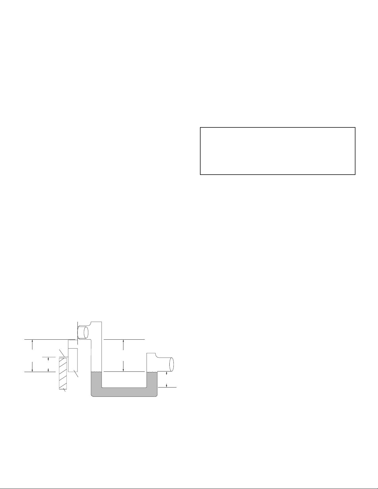
A label with recommended trap height is provided on the
unit as per Figure 3.
Condensate drain must be trapped as shown.
Refer to IOM for further instructions and maintenance.
Le drain de condensation doit être fabriqué et intallé tel que
le croquis ci-bas. Voir le manuel d’installation,
opération et maintenance pour instructions.
Curb
6.578”
[167.08 mm]
support
3.375”
[85.73 mm]
6.0” [191 mm]
minimum
unexpected high head pressure and poor cooling/heating
performance. Manual shut-off valves are recommended to
be installed for the convenience of future service.
A circuit balancing valve with pressure and temperature
gauge connections is recommended to be installed in the
water line for balancing and service.
See Appendix K for water line eld mounted options and
accessories.
CAUTION
In areas where scaling can become serious, a periodic
cleaning for the water-to-refrigerant heat exchanger is
recommended. Standard water coil cleaning procedure
should be followed which must be done by a qualied service mechanic.
The trap height allows for the maximum suction pressure
after the cooling coil with intake damper, dirty pre and nal
high efciency lters, high efciency heat wheel plus 1” w.c.
per ASHRAE guidelines for outdoor units with intake hood
or indoor unit with up to 0.5” w.c. external static intake duct.
Slope the drain lines downward in direction of ow 1/8 inch
per foot referring to local codes for proper drainage requirements. Installing a plug for cleaning of the trap is recommended. Prime the trap by lling with water before start-up.
Winterize the drain line before freezing on outdoor units.
Check and clear drains annually at start of cooling season. Drainage problems can occur should drains be inactive and dry out, or due to reduced water ow caused
by buildup of algae. Regular maintenance will prevent
these from occurring.
Unit baserail
Curb
Figure 3: Condensate drain trap label
MAMM-VHC-IOM-1A (JANUARY 2013)
3.0”
minimum
PN 500005436
10
Page 11
Start-up
Pre Start-up Procedure
Before requesting start-up, check that the installation is
complete and unit is ready. Complete the pre start-up
check list below and in the Appendix H for each unit as
items are checked.
1. Set the electrical disconnect to the ‘Off’ position.
2. Check the unit for obstructive packaging, objects near
or in blowers, dampers, heat wheel, etc. Remove all
red tie down bolts on fan assemblies and heat wheel if
so equipped.
3. Check that the fans and heat wheel are rotating
freely.
4. Check blower wheels and drive set screws. Tighten if
required.
5. Check belt alignment and tension.
6. Check that the air lters are installed and clean. Replace if necessary.
7. Check coils (if equipped) if ns have been damaged
in transit or construction and are clean. Straighten ns
with n comb and clean coil if required.
8. Check the refrigerant components and piping that they
are in good condition and have no damage or leaks
from shipping or installation.
9. Check that the water strainer has been installed for a
WSHP with a brazed heat exchanger.
10. Check that ductwork is connected and complete.
11. Check that condensate drain connections have been
trapped, installed correctly and lled.
12. Check that all shipped loose or eld supplied components have been correctly installed and wired and that
start interlocks have been completed for the ventilation
control desired.
13. Check that the standard eld wiring (FW) terminal
diagram has been marked up accordingly and left with
the unit.
14. Check that all power supplies and control wiring have
been inspected and approved by the Local Authorities
having jurisdiction.
15. Check all factory and eld wiring connections for tightness. Tighten if necessary.
16. Check that all fuses are properly installed in holders.
17. Check the voltage at the disconnect switch against the
nameplate and against phase-to-phase readings on
three-phase. If the voltage is not within 10% of rated
or 2% of phase-to-phase, have the condition corrected
before continuing start-up.
18. Check that all eld piping and venting installation and
connections for the heating and cooling options have
been completed and test.
19. Set the heating and cooling enable switches to the
‘Off’ position.
Start-up Procedure
To ensure proper operation of each unit, qualied personnel should perform the start-up and complete the checklist
below and the start-up report in Appendix H for permanent
record. A completed checklist will provide valuable information for personnel performing future maintenance.
IMPORTANT
A completed copy must be sent back to the factory for
warranty validation and for factory assistance.
All units are factory run tested. Blowers, heat wheel and
compressors (if equipped) are set up to run correct when
power is connected. If any one blower is running backwards or compressor is making loud noises disconnect
power and switch two leads (on three-phase power) to ensure proper rotation and avoid damage.
If units are equipped with compressors power must be
turned on for 24 hours prior to a call for cooling, for the
compressor crank case heaters to be energizing to prevent
possible damage.
The BacStat II interface module (if equipped with DDC control package and mounted remotely) may be temporarily
connected at the unit for checkout. Ensure it is connected
to the Net 2 contacts otherwise it will not give readings.
1. Before proceeding complete the pre start-up checklist.
2. Check that all access panels or doors are closed.
3. Turn the main disconnect to the ‘On’ position.
4. Set the timer, selector switch or BMS contact to the
ventilation control scheduling mode selected and
check operation according to sequence. Only one of
the following modes selected can have their contacts
closed or jumped.
a. Occupied ventilation (Ov): With the occupancy
contact closed or a jumper placed across terminals, heat wheel starts (not in free cooling), defrost recirculation damper closes (if equipped),
outside and exhaust air dampers open fully,
the supply blower starts and after exhaust air
damper opens fully, the exhaust blower starts.
b. Unoccupied recirculation (Ur): With the unoc-
cupied recirculation contact closed or a jumper
MAMM-VHC-IOM-1A (JANUARY 2013)
11
Page 12

placed across terminals, heat wheel stops,
defrost recirculation damper opens, outside
and exhaust air dampers (if equipped) begin to
close and supply blower starts.
c. Occupied recirculation (Or) (DDC control pack-
age only): With the occupied recirculation
contact closed or a jumper placed across terminals, heat wheel starts (not in free cooling), defrost recirculation damper closes (if equipped),
outside air damper (if equipped) opens. After
outside air damper opens supply blower starts,
exhaust air damper (if equipped) opens; after
exhaust air damper opens, exhaust blower
starts, occupied recirculation damper opens,
outside and exhaust air dampers modulate to
the damper minimum setpoints.
5. Check that dampers are operating properly.
6. Check that blowers and heat wheel are rotating in the
correct direction.
7. For occupied recirculation scheduling mode the outside air and exhaust air dampers must be adjusted
during start-up to achieve the required outside and exhaust air volumes. See Airow Balancing for further
information.
8. Re-check the voltage at the disconnect switch against
the nameplate and against phase-to-phase readings on three-phase with all blowers operating. If the
voltage is not within 10% of rated or 2% of phase-tophase have the condition corrected before continuing
start-up.
9. Check amperage draw to each motor on each
phase against motor nameplate FLA. If signicantly
different, check ductwork static and/or take corrective action.
10. Before activating the compressor on WSHP units, are
water shut-off valves open and is water circulating
through the water-to-refrigerant heat exchanger.
11. Enable cooling and check if the sound of the compressor is normal or if there is excessive vibration.
12. Check all eld and factory refrigerant and water piping
connections for leaks and correct.
13. Enable heating options, see start-up and check out instructions in Appendix J for electric coil and complete.
14. Check the operation of the control options provided
on the unit. A functional description is provided below
and in the VHC-36, 42 and 50 DDC Control Package
Manual.
15. Check the setpoints on the DDC Points Reference,
adjust and record changes as required.
16. When unit has achieved steady state take measurements and complete the readings section of the start-
up report in Appendix H and send copy of the start-up
report to Mammoth to validate warranty. Maintain a
copy of the report at the unit for future reference.
Optional Controls and Accessory Sequence and Interlocks
Free Cooling
Power connected, unit ventilating, free cooling call. Wheel
stops rotating.
Variable Speed Setpoint Free Cooling
Power connected, unit ventilating. Wheel modulates to
keep discharge temperature air at setpoint.
Unit Fault
An external unit fault can be initiated by removing the
dry contact jumper to the eld wire terminal in the control
panel. This contact is normally closed and requires an
open contact to initiate a fault and shut down the unit.
Dirty Filter Sensor
The VHCs can be equipped with dirty lter sensors which
monitor the pressure across the lters and close the contacts when the lters become restricted with dirt. Field
wired connections can be made to the terminal interface
MAMM-VHC-IOM-1A (JANUARY 2013)
for both the supply and exhaust lter sensors (electro-mechanical controls [EMC] units only).
Remote Fan Control
Remote fan control can be achieved by connecting dry
contacts to the terminal interface (during occupied or unoccupied recirculation). These controls could also be the
following: SPDT switch, dehumidistat, CO2 sensor, light sensor, heat sensor, timer, Building Management System, etc.
CO2 Ventilation Control
VHCs can be directly controlled by a CO2 controller (accessory or eld supplied) that can be connected to the supply
and exhaust high speed contact terminals (VFD units only).
As the CO2 levels exceed acceptable limits, dry contacts
close raising high speed fan ventilation. See Appendix F,
CO2 Ventilation Control. Alternatively a eld supplied CO2
controller output can be connected to the BMS which can
then be connected to the supply and exhaust fan modulating signal input terminals (VFD units only). As the CO2
12
Page 13
levels rise and fall the BMS must modulate the signal to
the supply and exhaust fans to change the ventilation rate
proportionally. See Appendix G. The minimum VFD speed
is factory default set to 40 Hertz.
Smoke Detector
VHCs can be equipped with a duct mount smoke detector
which will monitor the air when passing through the duct
system into the unit. When sufcient smoke is detected, an
alarm condition is activated. By connecting the occupied
terminals to the NC alarm auxiliary contacts on the duct
sensor, an alarm condition will open the auxiliary contact
and stop operation of the VHC. Locate in a normally occupied area of premises. Recommended for compliance to
NFPA-90A and IMC code 606.
Cooling Override (DDC Controls Units Only)
These terminals are available for a room or return air summer thermostat. All thermostats are eld installed and wired.
Dehumidication (DDC Controls Units Only)
IMPORTANT
Removal of dry contacts that close on high speed terminals is required for VFDs to modulate.
These terminals are available for a room or return air dehumidistat. All dehumidistats are eld installed and wired.
Heating Override (DDC Controls Units Only)
These terminals are available for a room or return air winter
thermostat. All thermostats are eld installed and wired.
For standard eld wiring terminals diagram, refer to Appen-
dix G.
Frost Control
During cold temperatures, defrost and frost prevention are
controlled by the unit’s integrated controls as follows.
Preheat will prevent frost formation on the enthalpy wheel
to maintain proper operation and provide continuous ventilation and make-up air. This prevention occurs when a preheater is energized to maintain an outdoor air temperature
higher or when the wheel speed is reduced to maintain an
exhaust air temperature higher than minimum required for
the enthalpy wheel to operate frost free.
The requirement for frost control is based upon the outdoor
air temperature and humidity content of the return air. In
areas where the winter outdoor air condition falls below 5°F
[−15°C] or the return air relative humidity is above 30%,
frost control is probably required.
Preheat Frost Prevention
Preheat frost prevention is an outdoor air temperature
controlled function that allows for continuous ventilation by
ensuring a minimum enthalpy wheel entering air temperature of 5° F [−15°C]. The temperature sensor is located between the open wire electric heating coil and the enthalpy
wheel. The electric heating coil is selectable in 1 kW increments and available in two-stage, four-stage or SCR control. With staged control, one stage cycles to maintain 5°
F [−15°C] temperature to the enthalpy wheel as the other
stages are continuously on as the outdoor air temperature
drops. If the selected kW is insufcient, based upon the
entered design conditions, selection software automatically
adjusts the minimum kW required to maintain the minimum
wheel entering air temperature.
Non-defrost
No frost control is required in areas where the winter outdoor air condition stays above 5°F [−15°C] and the return
air humidity level is below 30%.
MAMM-VHC-IOM-1A (JANUARY 2013)
13
Page 14
!
Airow Balancing
IMPORTANT
On initial power up, the unit will perform a system check
and operate at high speed for ve seconds.
For proper performance the unit must operate and be
balanced at the design supply and exhaust airow rates.
Permanent or temporarily eld supplied and installed ow
measuring stations (FMS) can be used to measure airow
or by using other ASHRAE suggested methods. Where
space is limited in the outdoor air or exhaust air ducts
for measurements, pressure drop readings can be taken
across the enthalpy wheel rotor and airow extrapolated
from the curves in Appendix L for the wheel effectiveness
category or thickness. Heat recovery performance is tested
in accordance to AHRI Standard 1060 and is accurate to
within +/− 5% if there is no dirt buildup in the heat recovery
wheel rotor.
When FMS are used it is important to locate it in the “warm
side” ductwork to minimize the effects of differences in air
density especially during cold outside conditions. Air density variations can affect the FMS by more than 15%. The
FMS should be located downstream from straight sections
of duct and not immediately after fans or obstructions that
will cause turbulent ow.
coils or reheat to protect building systems must be eld
provided.
Setting Flow Rate
Units supplied with belt driven double width double inlet
fans have an adjustable motor sheave factory set at the
midpoint of travel at rpm for the ow rate and external static
specied. With optional VFD driven motors this factory setting is at 60 Hz. For 100% outdoor and exhaust, ow rate
should be balanced with motors operating at high speed
and at 60 Hz by adjusting the motor sheave pitch diameter.
The VFD can be used for ne tuning depending on sequence.
With the optional direct driven plenum supply fan the VFD
is used for speed setting and balancing at the required
Hertz.
With the optional internal bypass the airow rate may be
reduced. Consult the factory for setting the ow rate during
internal bypass.
WARNING
Disconnect the main power switch to the unit before performing service and maintenance procedures.
Imbalanced airow may cause supply air temperatures
to be below freezing. Adequate freeze protection such as
glycol or low limit temperature protection for downstream
MAMM-VHC-IOM-1A (JANUARY 2013)
14
Page 15
Service
Quarterly Maintenance
Quarterly maintenance (every three months) should include:
Air Filters
The standard medium efciency lters and optional high efciency lters are disposable and should be replaced every
three months. More frequent replacement may be required
under extremely dirty operating conditions.
To replace the lters, open the lter access door, grasp the
lters and pull straight out. The lters will slide completely
Annual Maintenance
Annual maintenance should include:
Aluminum Enthalpy Wheel
No cleaning of the enthalpy wheel is required as it is
self-cleaning due to the opposing airows. If it is desired
to clean the enthalpy wheel, use low pressure air or a
vacuum. Wash the cassette panels with a soft cloth and
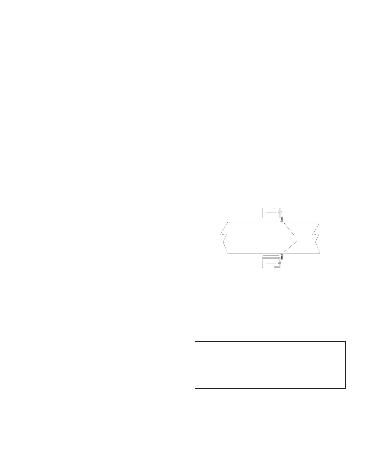
mild cleaning solution. Visually inspect the cassette brush
seals (shown in Figure 4), perimeter seal and drive belt
for proper operation.
out of the unit. Slide the new lters into the frame and close
the lter access door.
Cassette Panels and Interior of Unit
Remove the lters from the unit. Wipe the foil faced insulation, or the optional interior galvanized liner, surfaces
and cassette panels with a soft cloth and mild cleaning
solution.
System Operation Check
Verication of all control modes should be checked to ensure proper operation. Refer to Start-up section.
Rotor
Brush seal
Fans
Blower wheels and fan housing should be checked for dirt
buildup. If they are dirty, it will be necessary to remove the
blower assembly to clean the dust out through the fan mouth.
Dirt on the surface of the coil reduces its ability to transfer
heat which lowers the efciency of the unit, resulting in
poor air quality and expensive operating costs. Because
of the condensate on the coil, the dirt often becomes wet
and contributes to the growth of microbial organisms.
Negligence in maintenance may result in serious health
related indoor air quality problems.
The coil should be kept clean for maximum performance.
To achieve maximum efciency, clean the coil often during
periods of high demand or when dirty conditions prevail.
Mammoth recommends cleaning the coil a minimum of
once per year to prevent dirt buildup in the coil ns where
it may not be visible.
Coil ns can be cleaned by using steam with detergent, hot
water spray or a commercial chemical coil cleaner. After
cleaning the coil, be sure to rinse thoroughly.
Figure 4: System operation check
Coils
Cleaning Procedure
CAUTION
Do not use acidic chemical coil cleaners. Do not use alkaline chemical coil cleaners with a pH value greater than
8.5 or lower than 6 (after mixing) without using an alu-
minum corrosion inhibitor in the cleaning solution. Using
these types of cleaners may result in unit damage.
1. Shut down the unit by closing the main disconnect
at the power inlet.
2. Open panels or doors to gain access to both sides of
the coil section.
3. Remove soft debris from both sides of the coil with a
soft brush.
MAMM-VHC-IOM-1A (JANUARY 2013)
15
Page 16
WARNING
!
Disconnect the main power switch to the unit before performing service and maintenance procedures.
4. Using a steam cleaning machine, clean the leaving
airside of the coil rst (going downward) then clean the
entering airside. Use a block-off to prevent the steam
from penetrating a dry section of the unit.
5. Allow the unit to dry thoroughly before restoring power.
Testing and Replacement of the Damper Actuator
6. Damaged coil ns (excluding brazed aluminum)
should be straightened by using a n comb.
7. Close all panels and doors once the coil is dry.
8. Restore electrical power to the unit.
After disconnecting the power from the unit, determine
if the actuator is defective. Disconnect the 24 volt power
source. Connect the actuator directly to a 24 volt power
source with an appropriate cable. If the damper operates
correctly, the problem is either in the wiring connections
or main circuit board.
Motor and Blower Removal – Down, Side and End Supply/Exhaust
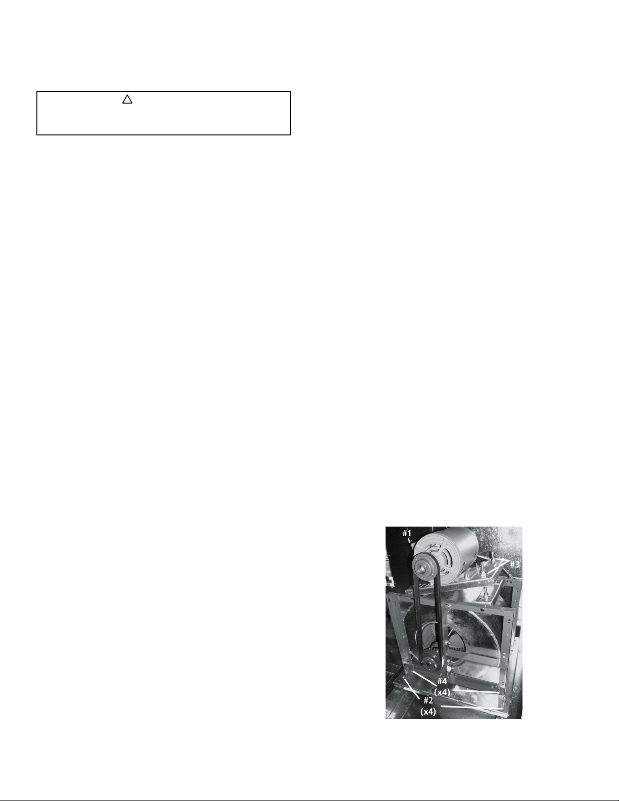
Disconnect the four-wire service connector from the
motor (#1, Figure 5). Loosen the four bolts (#2, Figure
5) and all screws that fasten the blower to the ex collar.
Motor and Blower Service – Down, Side and End Supply/Exhaust
The belt tension is adjusted by the positioning of the rotating motor base plate. Loosen the two adjustment bolts
(#4, Figure 5) on the base plate. Rotate the motor and
base plate to achieve the maximum belt deection as
described under belt tension adjustment below. Tighten
the adjustment bolts (#4, Figure 5). Verify that the
sheave and pulley faces are still parallel. The fan rpm
can be adjusted to achieve the design airow by setting
the adjustable sheave on the motor shaft. The pulley set
screw torque setting is 110 in.-lbs to 130 in.-lbs.
If the actuator does not work, it must be replaced. Loosen
the nuts on the jack shaft clamp and remove the actuator. Tighten the clamp on the damper jack shaft. Test for
proper operation.
Slide the fan assembly out of the unit. The fan assembly
may have to be lifted over the fan assembly plate bolts
(#3, Figure 5).
Figure 5: Motor and blower orientation for down, side and
end supply/exhaust options
MAMM-VHC-IOM-1A (JANUARY 2013)
16
Page 17
!
Belt Tension Adjustment
!
WARNING
Disconnect the main power switch to the unit before performing service and maintenance procedures.
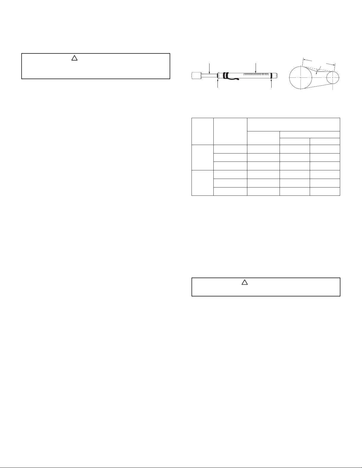
1. Measure the belt span with a span scale (see Figure
6).
2. Divide the belt span by 64 to determine the belt deection needed to check tension.
3. Set the O-ring on the span scale to the required deection value.
4. Set the small O-ring at zero on the force scale.
5. Place the scale end of the tension checker squarely
on one belt at the center of the belt span. Apply force
on the plunger until the bottom of the large O-ring is
even with the top of the next belt or until it is even with
a straight edge laid across the sheaves.
6. Read the force scale under the small O-ring to
determine the force required to give the needed
deection.
7. Compare the force scale reading in Step 6 with the
correct value for the belt style and cross section. The
force scale reading should be between the minimum
and maximum values shown in Table 2.
8. If the deection value is below the minimum, tighten
the belts. If the deection value is above the maximum, loosen the belts. The tension on new belts
Plunger with
deflection force scale (lbs)
Small O-ring Large O-ring
Body with deflection
distance scale (inches)
Figure 6: Belt tension adjustment
Table 2: Recommended Deection Force
V-belt
Cross
Sec-
tion
Small
Sheave
Diameter
Range
Recommended Deection Force
(lbs)
Initial
Installation
Re-tensioned
Maximum Minimum
3.0” to 3.4” 3.3 2.9 2.2
3.6” to 4.2” 3.5 3.1 2.4
A
4.6” to 6.0” 3.7 3.3 2.5
4.6” to 5.4” 6.0 5.1 4.0
B
5.6” to 7.4” 6.3 5.5 4.2
8.6” to 9.4” 6.6 5.7 4.4
should be checked during the rst day of operation, at
the end of the rst week and monthly thereafter.
Belt Span
Force
Deflection
Plenum Fan and Motor Removal
Disconnect the four-wire service connector between the
motor and the VFD (#1, Figure 7). Remove the four bolts
(#2, Figure 7) and slide the motor and plenum fan past the
inlet cone, then lift out of the unit. A 1¾” socket is required
to remove the fan from the motor shaft.
WARNING
No lubrication is necessary during servicing.
MAMM-VHC-IOM-1A (JANUARY 2013)
17
Page 18
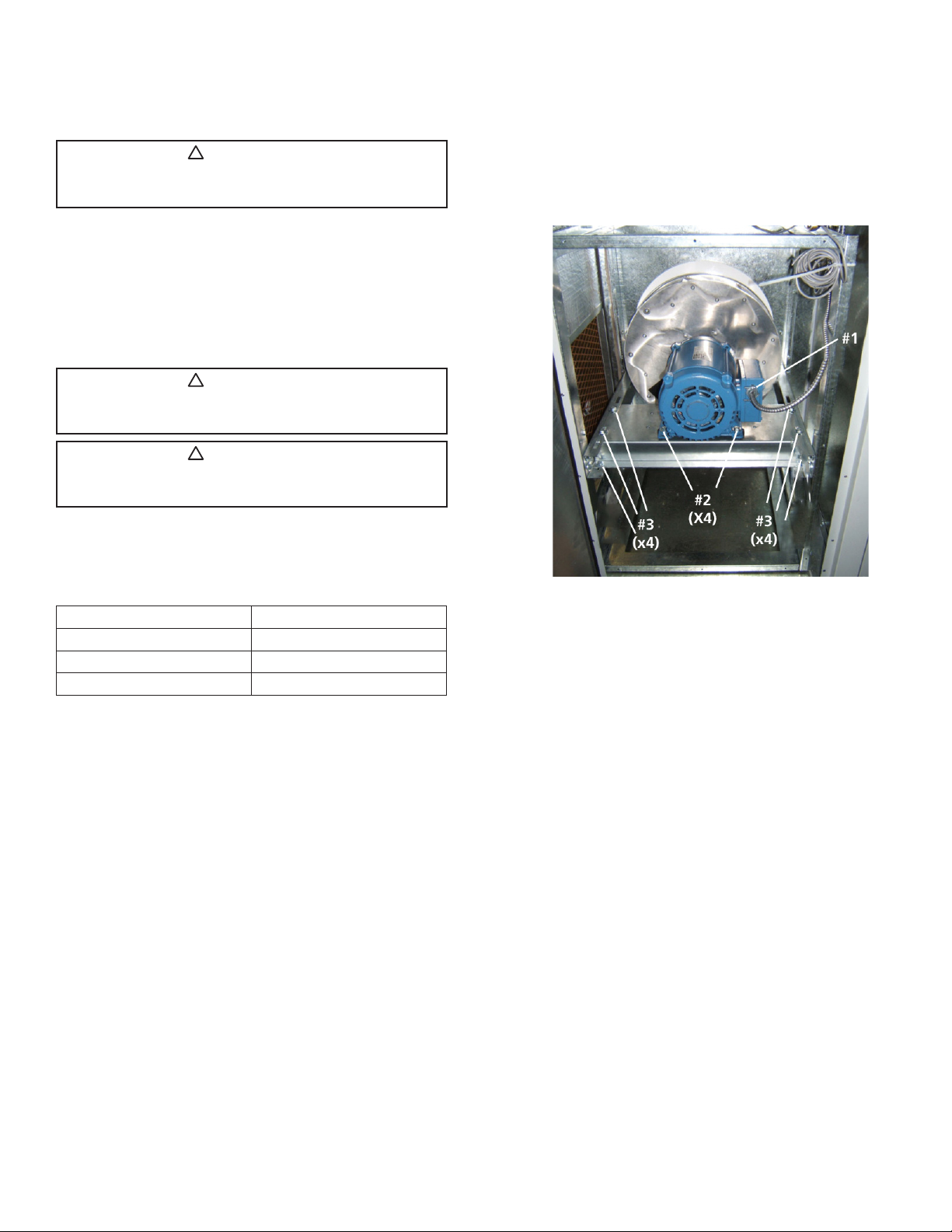
Plenum Fan and Motor Service
!
!
!
WARNING
Disconnect the main power switch to the unit before performing service and maintenance procedures.
Both motor shaft and fan bore must be completely free of
paint, grease, oil and dirt. If necessary, clean the surfaces
with non-petroleum based solvent, such as isopropyl alcohol. Insert the bushing into the fan, making sure the mating
hub is ush against the shoulder at the ats. Position the
assembly at the desired location on the motor shaft and
hand tighten nut (clockwise) until the assembly becomes
snug on the shaft.
WARNING
Do not hammer or use any type of impact to force the
bushing along the shaft.
WARNING
The shaft must fully engage the shaft gripping area of the
bushing.
Using a torque wrench and a 1¾” socket, tighten the nut to
the proper installation torque. See Table 3 for torque value.
Table 3: Torque Value
Shaft Size ft-lb
5/8” to 3/4” 100
13/16” to 1” 125
1-1/16” to 1¼” 167
Fan should overlap inlet cone by 3/8” [9 mm] and have a
clearance of 1/16” [2 mm]. Motor/fan assembly position is
adjustable by loosening the four bolts (#3, Figure 7) and
sliding shelf forwards and back.
Figure 7: Plenum fan and motor
Cassette Removal
After disconnecting the power from the unit, open the service door for the cassette access. Disconnect the service
connector between the motor and the control box. Remove
the exhaust lters and slide the cassette out of the unit.
MAMM-VHC-IOM-1A (JANUARY 2013)
Take care to not damage the rotor face or any of the cassette seals. Proper support must be provided so the cassette is not dropped.
18
Page 19
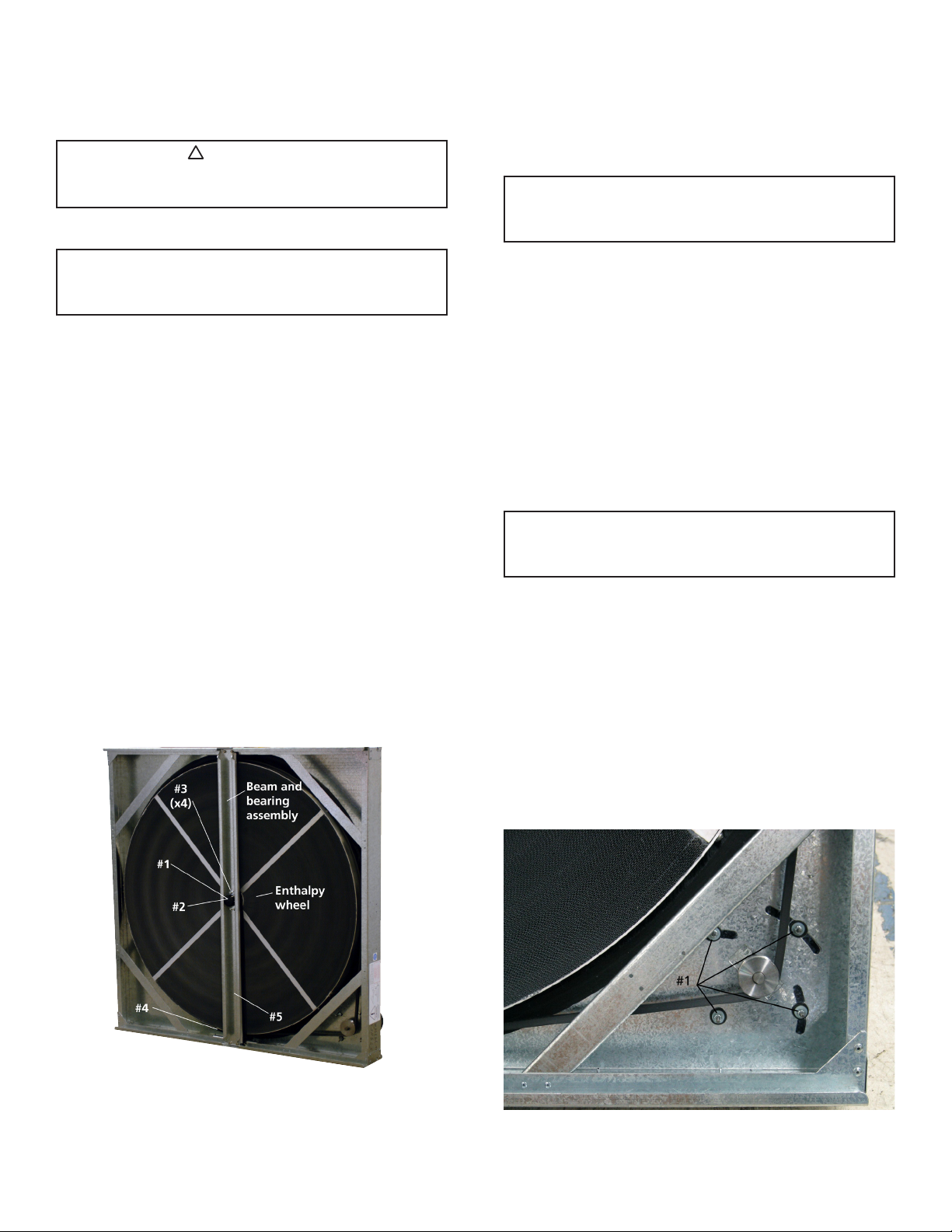
Cassette Service
!
WARNING
Disconnect the main power switch to the unit before performing service and maintenance procedures.
Perimeter Seal Replacement
CAUTION
When handling the enthalpy wheel, ensure not to damage
the face of the wheel.
To replace the perimeter seal, the enthalpy wheel must be
removed from the frame. Disconnect the service connector
to the drive motor of the enthalpy wheel cassette. Remove
the cassette from the unit and stand the assembly on the
oor or roof. Remove the dust cap (#1, Figure 8) from the
bearing on the drive motor side of the cassette. Remove
the bolt (#2, Figure 8) from the end of the wheel shaft with
a socket or wrench on the drive motor side. Repeat this
procedure for the other side of the cassette assembly. Remove the four bolts (#3, Figure 8) with a socket or wrench.
Remove the beam and bearing assembly from the end of
the wheel shaft. Loosen the four Nyloc nuts (#1, Figure 9)
holding the drive motor using a socket or wrench. Rotate
the drive motor in the slots to loosen the drive belt and
remove the belt. Lift the enthalpy wheel out of the frame
with assistance and set aside. Remove the perimeter seal
halves (#4, Figure 8) from the cassette frame assembly.
Install the two new perimeter seal halves by pressing them
into place, cutting to the correct length as is necessary. The
perimeter seals are non-adjustable. Complete the installation by reversing the above procedure.
Face Seal Replacement and Adjustment
CAUTION
When handling the enthalpy wheel, ensure not to damage
the face of the wheel.
To replace the face seals, the cassette assembly must be
removed from the unit. Disconnect the service connector
to the drive motor of the enthalpy wheel cassette. Remove
the cassette from the unit and stand the assembly up on
the oor or roof. Remove the screws holding the face seals
(#5, Figure 8). Replace the two seals (supply and exhaust
sides), cutting to length as required. Adjust the seals in the
slots so that the brush just touches the face of the wheel.
Complete the installation by reversing the above procedure.
Enthalpy Wheel Drive Belt Replacement
and Tensioning Adjustment
CAUTION
When handling the enthalpy wheel, ensure not to damage
the face of the wheel.
The enthalpy wheel drive belt can be tightened by sliding the cassette assembly only part way out of the unit.
Disconnect the service connector to the drive motor of
the enthalpy wheel cassette. Slide the cassette assembly
out of the unit enough to access the drive motor. Loosen
the four Nyloc nuts (#1, Figure 9) holding the drive motor
using a socket or wrench. Rotate the drive motor to loosen
the belt and replace the belt if necessary. Rotate the drive
motor in the slots to tighten the drive belt. Secure the motor
in its new location by tightening the four Nyloc nuts (#1,
Figure 8). Complete the installation by reversing the above
procedure.
Figure 8: Cassette and drive
Figure 9: Tension adjustment
MAMM-VHC-IOM-1A (JANUARY 2013)
19
Page 20
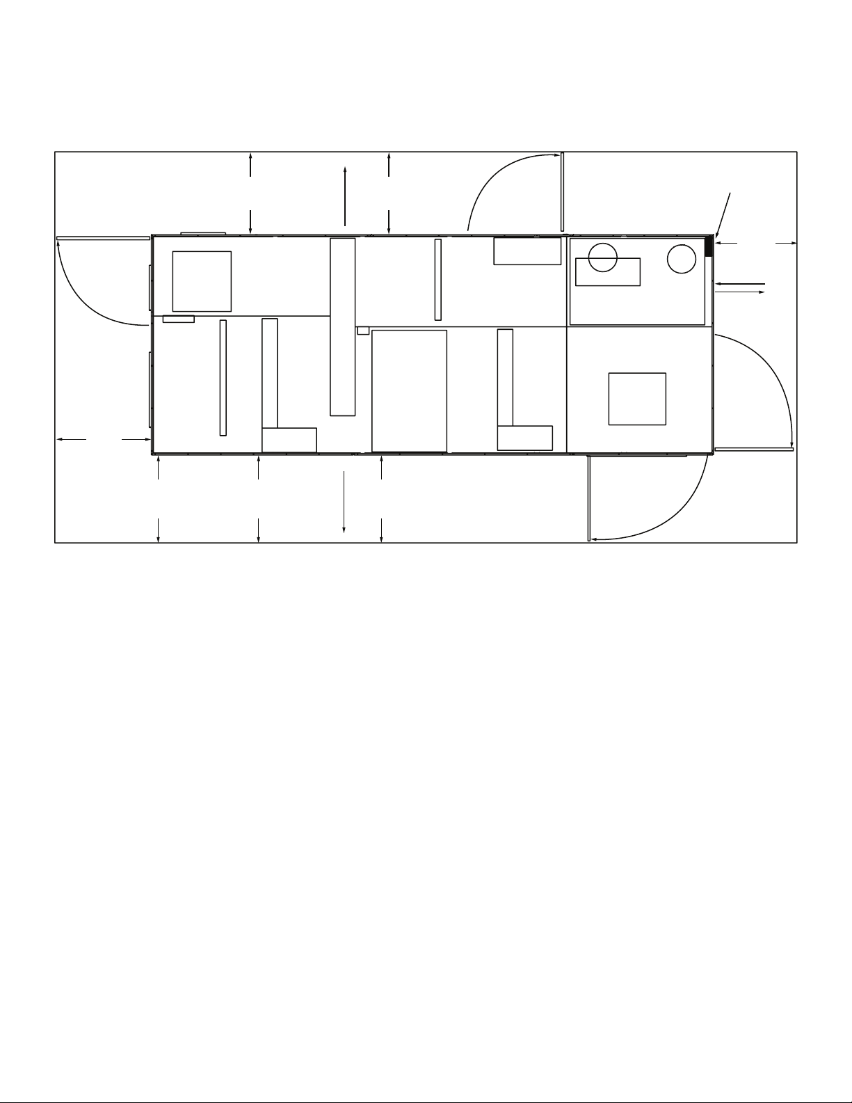
Appendix A: Service Clearance Dimensions
34.0”
[864]
Reverse cassette
removal
Exhaust
blower
Defrost or
unoccupied
recirc
damper
34.0”
[864]
**46.0”
[1,168]
* Clearance for enthalpy wheel removal.
** Clearance for S-OA intake hood.
Supply filters
Electric
preheat
34.0”
[864]
Enthalpy wheel
Standard cassette
removal
Figure A1: VHC with water source heat pump (WSHP)
*56.0”
[1,422]
Occupied
recirc or
return
damper
Cooling/heating
coil
*56.0”
[1,422]
Power line input
control wiring
36.0”
[914]
Water inlet
and outlet
connections
WSHP
Module
Supply
blower
CompressorCompressor
Control box
Coaxial coil
Exhaust filters
Electric
post heat
Note: All dimensions in [ ] are millimeters.
MAMM-VHC-IOM-1A (JANUARY 2013)
20
Page 21
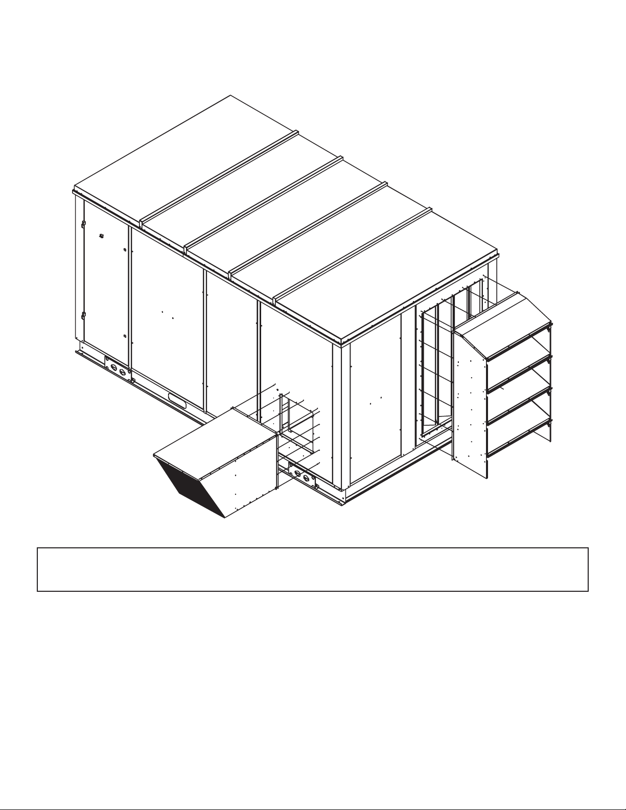
Appendix B: Hood Installation
Figure B1: Outdoor VHC hood installation
IMPORTANT
Complete wire connections between the unit and the hood by matching the correct wire colors on the actuator with the wire
colors on the schematic.
MAMM-VHC-IOM-1A (JANUARY 2013)
21
Page 22
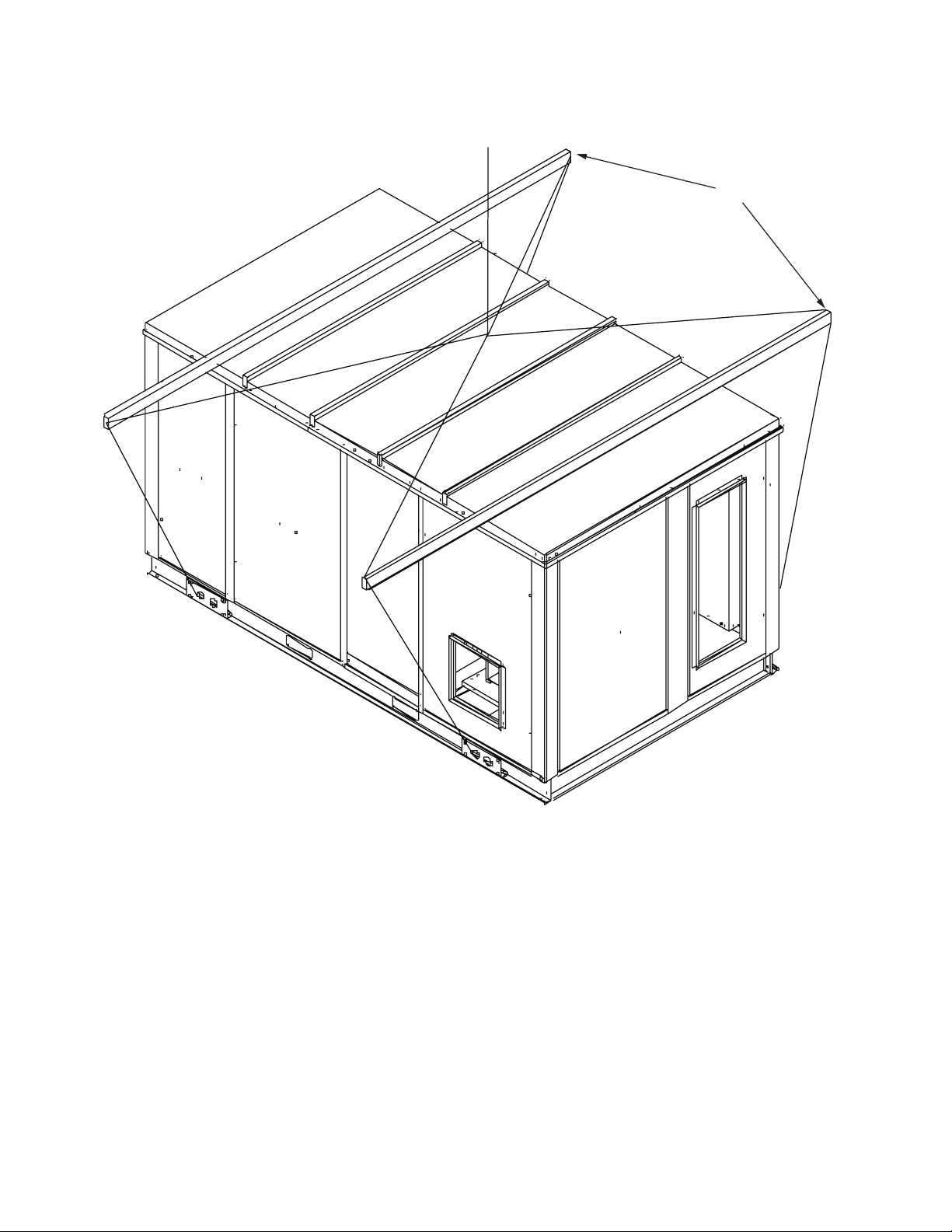
Appendix C: Rigging Drawing
Spreader bars
Figure C1: VHC rigging
MAMM-VHC-IOM-1A (JANUARY 2013)
22
Page 23

Appendix D: Equipment Data
Table D1: VHC-36, 42 and 50 Equipment Data
VHC-36 VHC-42 VHC-50
Fans
Supply type – Belt drive, ODP
Wheel type Forward curved Forward curved Forward curved
Bearing Pillow block Pillow block Pillow block
Motor (HP) 0.5 to 5 0.5 to 5 1 to 10
Supply type – Direct drive, ODP
Wheel type Backward inclined airfoil Backward inclined airfoil Backward inclined airfoil
Motor (HP) 0.5 to 5 0.5 to 5 1 to 10
Exhaust type – Belt drive, ODP
Wheel type Forward curved Forward curved Forward curved
Bearing Pillow block Pillow block Pillow block
Motor (HP) 0.5 to 5 0.5 to 5 1 to 10
Energy Recovery Module
4” wheel depth medium efciency
Wheel size 36” x 4” [914 x 102 mm] 42” x 4” [1,067 x 102mm] 50” x 4” [1,270 x 102 mm]
Cassette size
6” wheel depth standard efciency
Wheel size 36” x 6” [914 x 152 mm] 42” x 6” [1,067 x 152 mm] 50” x 6” [1,270 x 152 mm]
Cassette size
8” wheel depth high efciency
Wheel size 36” x 8” [914 x 203 mm] 42” x 8” [1,067 x 203 mm] 50” x 8” [1,270 x 203 mm]
Cassette size
Wheel substrate Aluminum Aluminum Aluminum
Wheel desiccant Silica gel Silica gel Silica gel
Wheel performance 0.20 to 0.90” w.g. 0.20 to 0.90” w.g. 0.30 to 1.00” w.g.
Filters
Supply and return
2” [51 mm] MEF
(MERV 7 30–35%)
4” [102 mm] MEF
(MERV 7 30–35%)
Supply only
4” [102 mm] prelter
MEF (MERV 7 30–35%)
4” [102 mm] prelter
HEF (MERV 14 80–85%)
Maximum Weight
Base unit, no heating or cooling 1,800 lbs [818 kg] 2,000 lbs [909 kg] 2,200 lbs [1,000 kg]
WSHP – add 590 lbs [268 kg] 755 lbs [343 kg] 890 lbs [405 kg]
Max unit 2,884 lbs [1,311 kg] 3,351 lbs [1,523 kg] 3,850 lbs [1,750 kg]
Roofcurb – add 210 lbs [95 kg] 250 lbs [114 kg] 270 lbs [123 kg]
40” x 40” x 4.5”
[1,016 x 1,016 x 114 mm]
40” x 40” x 6.5”
[1,016 x 1,016 x 165 mm]
40” x 40” x 8.5”
[1,016 x 1,016 x 216 mm]
1 of 20” x 20” [508 x 508 mm] &
1 of 16” x 20” [406 x 508 mm]
1 of 20” x 20” [508 x 508 mm] &
1 of 16” x 20” [406 x 508 mm]
1 of 20” x 20 “ [508 x 508 mm] &
1 of 16” x 20” [406 x 508 mm]
1 of 20” x 20” [508 x 508 mm] &
1 of 16” x 20” [406 x 508 mm]
46” x 46” x 4.5”
[1,168 x 1,168 x 114 mm]
46” x 46” x 6.5”
[1,168 x 1,168 x 165 mm]
46” x 46” x 8.5”
[1,168 x 1,168 x 216 mm]
1 of 18” x 24” [457 x 610 mm] &
1 of 24” x 24” [610 x 610 mm]
1 of 18” x 24” [457 x 610 mm] &
1 of 24” x 24” [610 x 610 mm]
1 of 18” x 24” [457 x 610 mm] &
1 of 24” x 24” [610 x 610 mm]
1 of 18” x 24” [457 x 610 mm] &
1 of 24” x 24” [610 x 610 mm]
54” x 54” x 4.5”
[1,372 x 1,372 x 114 mm]
54” x 54” 6.5”
[1,372 x 1,372 x 165 mm]
54” x 54” x 8.5”
[1,372 x 1,372 x 216 mm]
4 of 16” x 24” [406 x 635 mm]
4 of 16” x 24” [406 x 635 mm]
4 of 16” x 25” [406 x 635 mm]
4 of 16” x 25” [406 x 635 mm]
MAMM-VHC-IOM-1A (JANUARY 2013)
23
Page 24
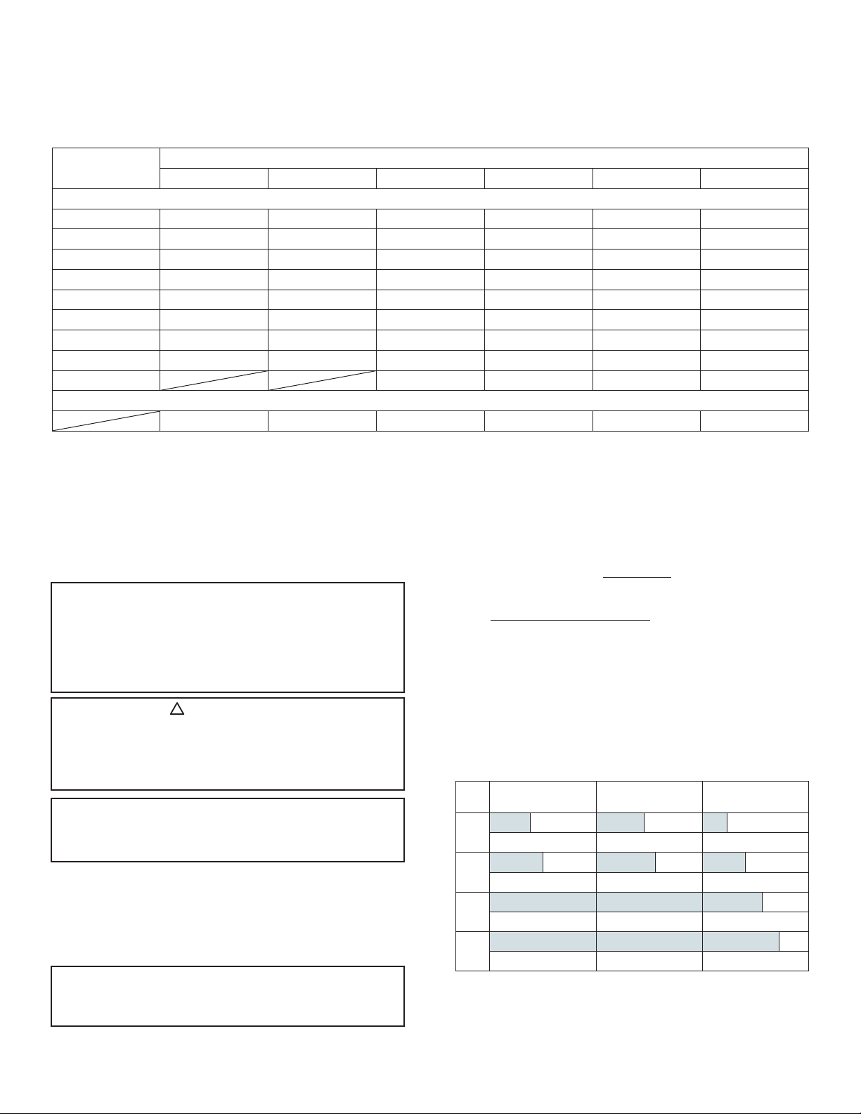
Appendix E: Electrical Data
!
Table E1: Full Load Amperage (FLA)
HP
0.5 4.5 4.0 1.8 2.2 1.1 0.9
0.75 5.4 6.0 2.7 2.7 1.4 1.1
1.0 6.8 7.0 3.4 3.4 1.7 1.4
1.5 10.2 10.2 5.0 5.0 2.5 2.0
2.0 14.0 14.0 6.4 6.0 3.0 2.4
3.0 17.8 17.0 10.6 10.6 4.8 3.4
5.0 22.0 22.0 15.3 12.8 6.4 5.1
7.5 32.0 32.0 25.0 19.2 9.6 7.8
10.0 29.3 26.8 13.4 10.3
208/1/60 230/1/60 208/3/60 230/3/60 460/3/60 575/3/60
Blower Motor
Wheel Drive Motor and Controls
2.4 2.2 2.4 2.2 1.1 0.9
The blower motor FLA values show in in the above table are for one motor only.
Voltage
Electric Preheat and Post Heat Calculation
FLA = W / (1.73 x voltage)
IMPORTANT
Electric preheaters and post heaters range from 1 to 120
kW (see below for heater limitations) and actual FLA values
of individual heaters will vary based upon the size, temperature rise and voltage. Consult the factory for actual FLA
values. All electric heaters require three-phase voltage.
WARNING
All units equipped with two-point electric post heaters
require two-point power connections, one to the control
panel and one to the electric heater fed from a eld supplied single disconnect.
CAUTION
All electrical installations and wiring require correct wire
gauge sizing and protection according to local building codes.
Electric Preheaters and Post Heaters
Electric preheaters and post heaters are available in:
• Single-point or two-point power connection
• Two-stage, four-stage* or SCR control
IMPORTANT
Four-stage electric post heaters are only available with
kW ratings higher than 10 kW.
Electric Heater Performance Calculations
Temperature Rise (°F) = kW x 3,160
cfm
kW = cfm x temperature rise (°F)
3,160
Electric single point preheaters and post heaters have the
following limitations:
• 208 VAC – 24 kW maximum
• 230 VAC – 27 kW maximum
• 460 VAC – 67 kW maximium
• 575 VAC – 84 kW maximum
Table E2: Electric Preheater and Post Heater Limitations
VHC-36 up to
VAC
50 kW
24 24 24
208
50 70 120
27 27 27
230
50 70 120
50 70 67
460
50 70 120
50 70 84
575
50 70 120
Shaded areas – single-point post heater limitations
White areas – two-point post heater limitations
VHC-42 up to
70 kW
VHC-50 up to
120 kW
• 1 kW increments for all three-phase voltages.
MAMM-VHC-IOM-1A (JANUARY 2013)
24
Page 25
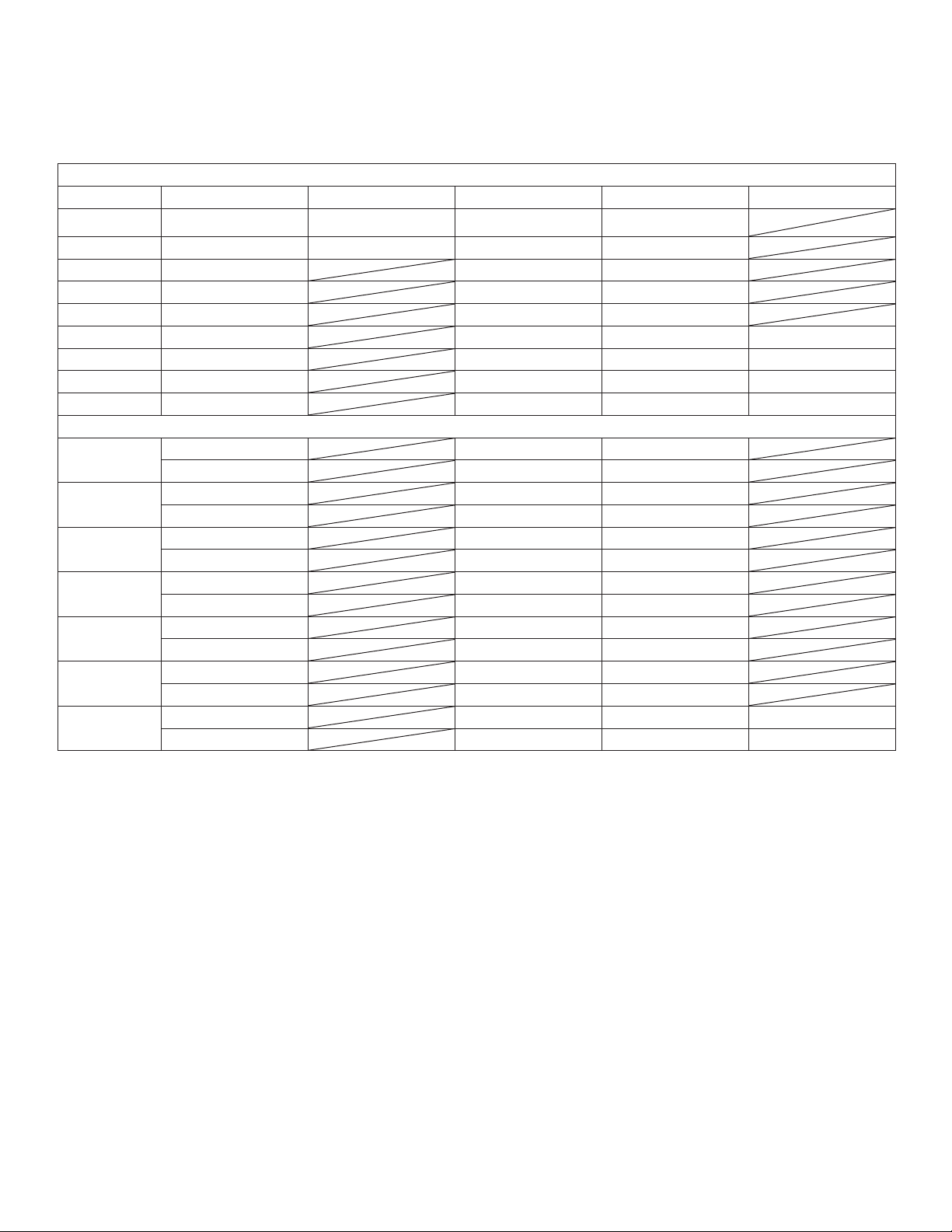
Table E3: Compressor Run Load Amperage (RLA)
Water Cooled Single Circuit
2 Two-stage 16.7 11.2 4.5 3.7
3 Two-stage 16.7 13.5 6.1
4 Two-stage 23.0 17.6 9.2
5 VRC
®
20.4 9.7
6 VRC 23.2 11.2
8 VRC 24.0 12.6
10 VRC 33.3 17.9 12.8
12 VRC 48.1 18.6 14.7
14 VRC 51.3 23.1 19.9
16 VRC 55.8 26.9 23.7
Water Cooled Dual Circuit
6
8
10
12
14
16
21
Crossed out areas indicate unavailable compressor selection.
Values indicated are for single compressor only.
On/off 13.2 6.0
VRC 11.7 6.2
On/off 14.5 6.2
VRC 17.9 7.8
On/off 20.5 9.6
VRC 20.4 9.7
On/off 23.2 10.6
VRC 23.2 11.2
On/off 25.0 14.7
VRC 24.0 12.6
On/off 29.5 14.7
VRC 24.0 12.6
On/off 33.3 17.9 12.8
VRC 33.3 17.9 12.8
MAMM-VHC-IOM-1A (JANUARY 2013)
25
Page 26
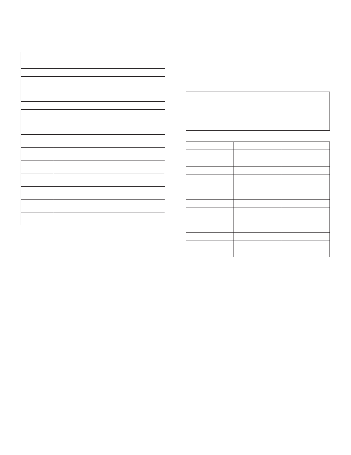
Table E4:
For Dual Circuit On/off Units
6 tons Two 3 ton on/off compressors
8 tons Two 4 ton on/off compressors
10 tons Two 5 ton on/off compressors
12 tons Two 6 ton on/off compressors
14 tons Two 7 ton on/off compressors
16 tons Two 8 ton on/off compressors
21 tons Two 10 ton on/off compressors
For Dual Circuit VRC® Units
6 tons
8 tons
10 tons
12 tons
14 tons
16 tons
21 tons
One 3 ton on/off compressor
One 3 ton VRC compressor
One 4 ton on/off compressor
One 4 ton VRC compressor
One 5 ton on/off compressor
One 5 ton VRC compressor
One 6 ton on/off compressor
One 6 ton VRC compressor
One 7 ton on/off compressor
One 7 ton VRC compressor
One 8 ton on/off compressor
One 8 ton VRC compressor
One 10 ton on/off compressor
One 10 ton VRC compressor
Minimum Current Ampacity (MCA)
Calculation
1.25 x FLA of larger hp motor or compressor = _____
1.25 x heater FLA = + _____
Sum of all other motors FLA = + _____
Wheel drive motor and standard controls FLA = + _____
Calculated total MCA = _____
Finding the Actual MOP Value
From the calculated MOP value, select the next smallest
value of protection from the Standard Overcurrent Protection chart below to get the actual MOP value (maximum
value of overcurrent device).
IMPORTANT
If this method leads to an actual MOP value being smaller
than the calculated total MCA, then a larger value must
rather be selected, such that the actual MOP is at least
equal to the calculated total MCA.
Table E5: Standard Overcurrent Protection
3 40 250
4 45 300
5 50 350
6 60 400
7 70 450
8 80 500
9 90 600
10 100 650
12 110 700
15 125 750
20 150 800
25 175 850
30 200 900
35 225 1,000
Maximum Overcurrent Protection (MOP)
Calculation
2.25 x FLA of larger hp motor or compressor = _____
Electric heater FLA = + _____
Sum of all other motors FLA = + _____
Wheel drive motor and standard controls FLA = + _____
Calculated total MCA = _____
Actual MOP (from Table E5) = _____
MAMM-VHC-IOM-1A (JANUARY 2013)
26
Page 27
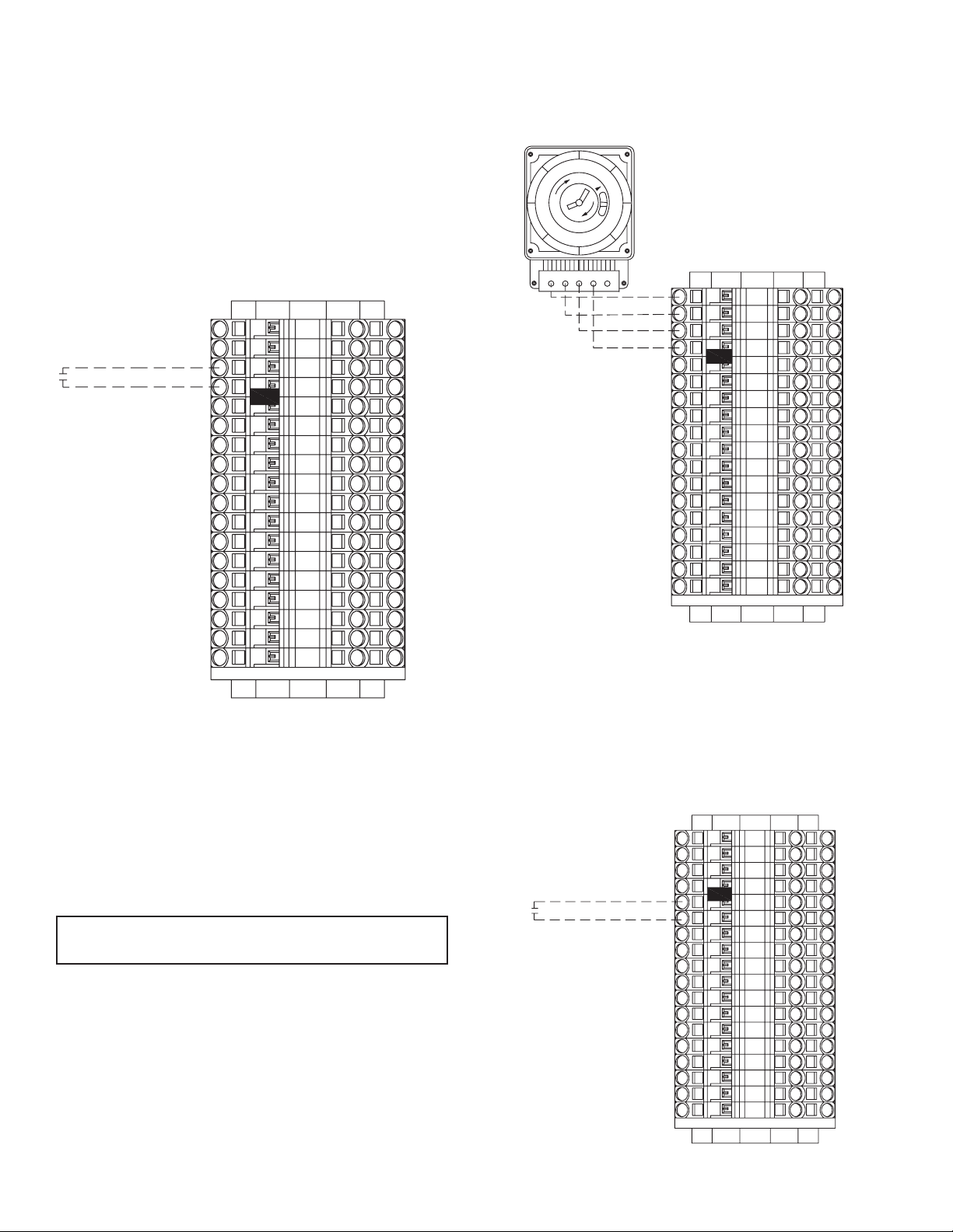
Appendix F: Terminal Control Diagrams
Occupied Ventilation
Occupied ventilation is achieved by closing the occupancy
contact to the terminal interface shown in Figure F1. These
terminals require a dry contact which could be provided by
a number of types of controls such as a timer, light sensor,
occupancy sensor, Building Management System or other.
The unit will not operate unless these contacts are closed.
301
302
OCCUPANCY
CR
CONTACT
Note: This is the only
connection needed to
start single-speed units.
304
305
305
306
307
308
320
321
322
323
324
325
374
375
376
377
12
9
6
234
5
1
301
302
304
305
305
306
307
308
320
321
322
323
324
325
326
327
328
329
Figure F2: Occupied ventilation for DDC controls package
and electro-mechanical controls (EMC)
Figure F1: Occupied ventilation for DDC controls package
and electro-mechanical controls (EMC)
Occupied Timer Sensor
Occupied ventilation is achieved by connection to the
terminal interface shown in Figure F2. These terminals require a dry contact which could be provided by a number of
types of controls such as a timer, light sensor, occupancy
sensor, Building Management System, or other. The unit
will not operate unless these contacts are closed.
IMPORTANT
DDC units can be turned on/off through software.
Unoccupied Recirculation
Supply fan recirculation for heating and cooling can be
achieved by connecting dry contact controls to the terminal
interface provided in the control panel area. This terminal
requires a dry contact closure from a eld provided and
wired device.
301
302
304
305
UNOCCUPIED RECIRCULATION
CR
CONTACT (OPTIONAL)
305
306
307
308
320
321
322
323
324
325
326
327
328
329
MAMM-VHC-IOM-1A (JANUARY 2013)
Figure 10: Unoccupied recirculation for DDC controls units
27
Page 28
301
301
302
304
305
305
306
307
308
320
321
322
323
324
325
374
375
376
377
302
304
UNOCCUPIED
CR
RECIRCULATION
CONTACT (OPTIONAL)
305
305
306
307
308
320
321
322
323
324
325
326
327
328
329
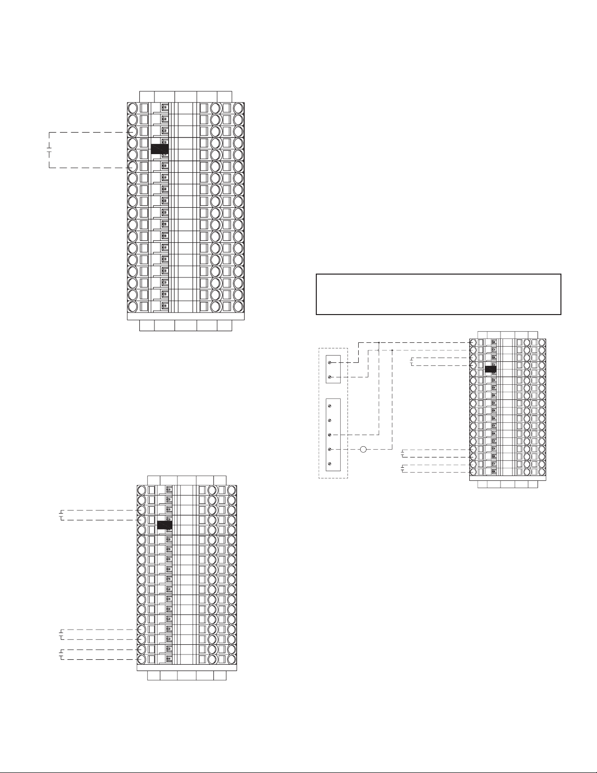
Figure F3: Unoccupied recirculation for electro-mechanical
controls (EMC) units
VFD High Speed Control
High speed fan control can be achieved by connecting dry
contact controls to the eld wired (FW) terminals 374 and
375 for the supply fan and 376 and 377 for the exhaust fan.
Only VFD units have the high speed option. These controls
could also be the following: DPST switch, dehumidistat,
CO2 sensor, light sensor, heat sensor, timer, Building Man-
agement System, etc.
301
302
304
305
305
306
307
308
320
321
322
323
324
325
374
375
376
377
OCCUPANCY
CR
CONTACT
SUPPLY BLOWER
CR
HIGH SPEED CONTACT
EXHAUST BLOWER
CR
HIGH SPEED CONTACT
Figure F4: VFD high speed control
MAMM-VHC-IOM-1A (JANUARY 2013)
CO2 Ventilation Control
VHCs can be directly controlled by a CO2 controller (accessory or eld supplied) that can be connected to the supply
and exhaust high speed contact terminals (VFD units only).
As the CO2 levels exceed acceptable limits, dry contacts
close raising high speed fan ventilation. See Figure F5.
Alternatively a eld supplied CO2 controller output can be
connected to the BMS which can then be connected to the
supply and exhaust fan modulating signal input terminals
(VFD units only). As the CO2 levels rise and fall the BMS
must modulate the signal to the supply and exhaust fans to
change the ventilation rate proportionally. See Appendix G.
The minimum VFD speed is factory default set to 40 Hertz.
IMPORTANT
Removal of dry contacts that close on high speed terminals is required for VFDs to modulate.
TB-1
TB-2
TB-1
TB-2
TB-3
RELAY CR1
TB-4
HIGH SPEED
CONTROL
TB-5
Figure F5: CO2 ventilation control
OCCUPANCY
CR
CONTACT
HIGH SPEED
CONTROL (SUPPLY BLOWER)
3
RELAY CR1
5
4
RELAY CR1
6
HIGH SPEED
CONTROL (EXHAUST BLOWER)
28
Page 29
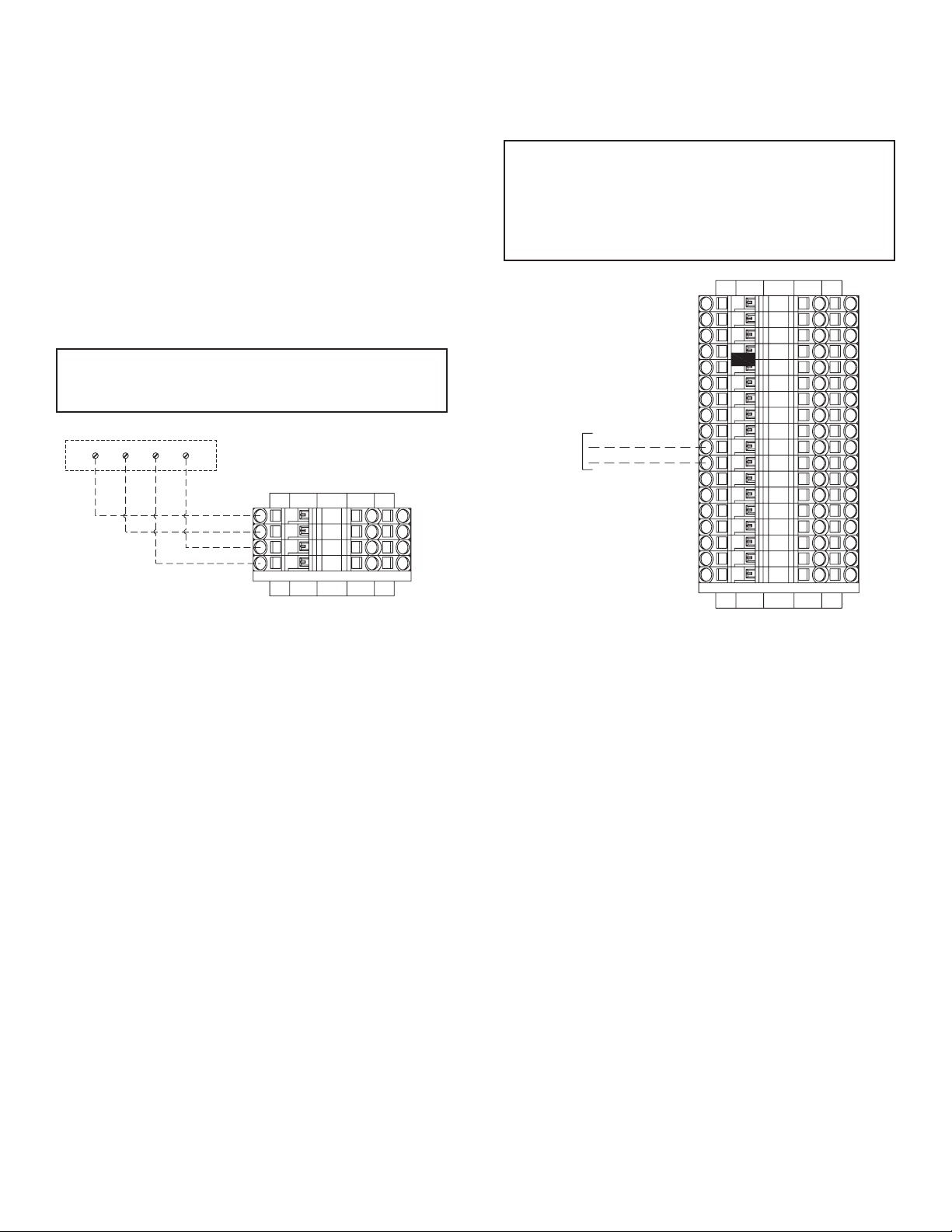
Smoke Detector
Locate in a normally occupied area of premises. Recommended for compliance to NFPA-90A and IMC Code 606.
VHCs can be equipped with a duct mount smoke detector
which will monitor the air when passing through the duct
system into the VHC. When sufcient smoke is detected,
an alarm condition is activated. By connecting the occupied
timer/sensor contacts to the NC alarm auxiliary contacts on
the duct sensor, an alarm condition will open the auxiliary
contact and stop operation of the VHC.
IMPORTANT
This wiring conguration cannot be used on DDC units
that are scheduled on/off through software.
1 2 15 16
24V 24V NC C
301
302
410
411
IMPORTANT
On DDC units, there is no dirty lter sensor output to connect to. Rather, the dirty lter sensor is connected to the
DDC controller and will display a dirty lter alarm on the
BacStat II (user interface) when it senses the lter is dirty.
301
302
304
305
305
306
307
308
24 VAC+ OUTPUTS
20 VA MAXIMUM
DIRTY SUPPLY FILTER
DIRTY EXHAUST FILTER
320
321
322
323
324
325
326
327
328
329
Figure F6: Smoke detector
Dirty Filter Sensor
The VHCs can be equipped with dirty lter sensors which
monitor the pressure across the lters and close the contacts when the lters become restricted with dirt. Field
wired connections can be made to the terminal interface for
both the supply and exhaust lter sensors.
Figure F7: Dirty lter control
MAMM-VHC-IOM-1A (JANUARY 2013)
29
Page 30
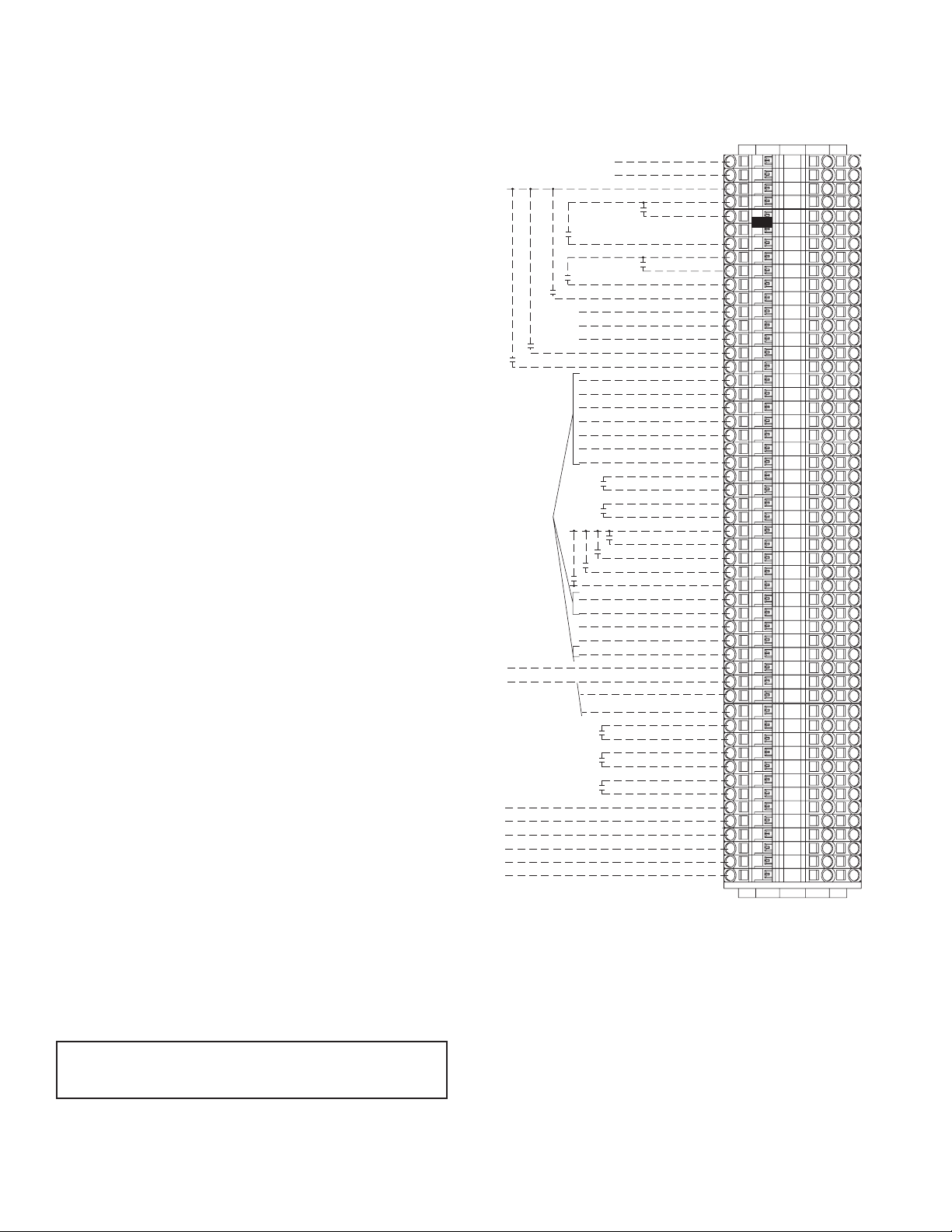
Appendix G: Standard Field Wiring (FW) Terminals
Control Field Wiring (FW)
Low voltage terminal control consists of the following:
Electro-mechanical Controls (EMC) Unit
Inputs
• Occupied ventilation timer/sensor
– Dry contact
• Occupied recirculation (if equipped)
– Dry contact
• Unoccupied recirculation (if equipped)
– Dry contact
• Unit fault
– Dry contact
• Cooling stage 1 (if equipped)
– Dry contact
• Cooling stage 2 (if equipped)
– Dry contact
• Heat enable (if equipped)
– Dry contact
• Modulating heat (if equipped)
– 0 to 10 VDC
• Reheat valve on/off 1 (if equipped)
– Dry contact
• Reheat valve on/off 2 (if equipped)
– Dry contact
• Reheat valve modulating (if equipped)
– 0 to 10 VDC
• Modulating supply motor speed (if equipped)
– 0 to 10 VDC
• Modulating exhaust motor speed (if equipped)
– 0 to 10 VDC
Outputs
• Supply fan on
• Exhaust fan on
• External unit fault
• Defrost on (if equipped with recirculation or exhaust
only defrost options)
• Free cooling on (if equipped with free cooling option)
• Wheel failure (if equipped with wheel rotation sensor
option)
• Dirty supply lters (if equipped with dirty lter sensor
option)
• Dirty exhaust lters (if equipped with dirty lter sensor
option)
• Cooling on (if equipped with cooling)
24 VAC+
24 VAC−
OCCUPANCY
CR
CONTACT
CR
UNOCCUPIED RECIRCULATION
CONTACT (OPTIONAL)
COOLING STAGE 1
CR
COOLING STAGE 2
CR
CONTACT (OPTIONAL)
GAS HEAT ENABLE
CR
CONTACT (OPTIONAL)
SCR ELECTRIC POSTHEAT (0–10 VDC+) (OPTIONAL)
SCR ELECTRIC POSTHEAT (0–10 VDC−) (OPTIONAL)
SCR ELECTRIC POSTHEAT (SHIELD) (OPTIONAL)
REHEAT VALVE 1
CR
CONTACT (OPTIONAL)
REHEAT VALVE 2
CR
CONTACT (OPTIONAL)
24 VAC+
OUTPUTS
MAXIMUM
HOT GAS REHEAT MODULATING (0–10 VDC+) (OPTIONAL)
HOT GAS REHEAT MODULATING (0–10 VDC−) (OPTIONAL)
SUPPLY BLOWER MODULATING (0–10 VDC+) (OPTIONAL)
SUPPLY BLOWER MODULATING (0–10 VDC−) (OPTIONAL)
SUPPLY BLOWER MODULATING (SHIELD) (OPTIONAL)
EXHAUST BLOWER MODULATING (0–10 VDC+) (OPTIONAL)
EXHAUST BLOWER MODULATING (0–10 VDC−) (OPTIONAL)
EXHAUST BLOWER MODULATING (SHIELD) (OPTIONAL)
FREE COOLING ON (OPTIONAL)
DIRTY SUPPLY FILTER (OPTIONAL)
DIRTY EXHAUST FILTER (OPTIONAL)
WHEEL FAILURE (OPTIONAL)
SUPPLY BLOWER ON
EXHAUST BLOWER ON
COIL LOW LIMIT (OPTIONAL)
CR
20 VA
CR
CR
ELECTRIC HEAT STAGE 3
CR
CONTACT (OPTIONAL)
ELECTRIC HEAT STAGE 4
CR
CONTACT (OPTIONAL)
COOLING STAGE 1 (ON) (OPTIONAL)
HEATING (ON) (OPTIONAL)
GAS HEAT MODULATING (0–10 VDC−) (OPTIONAL)
GAS HEAT MODULATING (0–10 VDC+) (OPTIONAL)
COOLING STAGE 2 (ON) (OPTIONAL)
COMPRESSOR ONE STATUS (OPTIONAL)
COMPRESSOR TWO STATUS (OPTIONAL)
CR
CR
CR
CONTACT (OPTIONAL)
GAS HEAT STAGE 2
(OPTIONAL)
SCR ELECTRIC HEAT ENABLE
CONTACT (OPTIONAL)
ELECTRIC HEAT STAGE 1
CR
CONTACT (OPTIONAL)
ELECTRIC HEAT STAGE 2
CONTACT (OPTIONAL)
SUPPLY BLOWER HIGH SPEED
CONTACT (OPTIONAL)
EXHAUST BLOWER HIGH SPEED
CONTACT (OPTIONAL)
UNIT FAULT
Figure G1: Electro-mechanical controls (EMC)
301
302
304A
304
305
305
306
307
308
309
310
311
312
313
314
315
320
321
322
324
325
326
329
352
353
354
355
356
357
358
359
360
361
362
363
364
368
370
371
372
373
374
375
376
377
410
411
501
502
502-S
503
504-S
504
IMPORTANT
All output controls are 24 VAC unless otherwise indicated.
MAMM-VHC-IOM-1A (JANUARY 2013)
30
Page 31

Appendix H: VHC-36, 42 and 50 Start-up Report and Checklist
IMPORTANT
• Complete this form for each unit and email, fax or
mail to Mammoth immediately after start-up to validate warranty and to provide valuable information for
personnel performing future maintenance or for factory assistance to address below.
• Read the Installation, Operation and Maintenance
Instructions Manual and the VHC-36, 42 and 50
DDC Control Package Manual (if equipped) before
proceeding.
• Leave a copy of this report with the owner and at the
unit for future reference and permanent record.
• To ensure proper operation of each unit qualied
personnel should perform the start-up, complete the
checklist and report.
• All units are factory run tested. Blowers, heat wheel
and compressors (if equipped) are set up to run
correct when power is connected. If any blower is
running backwards or compressor is making loud
noises disconnect power and switch two leads (on
three-phase power) to ensure proper rotation and
avoid damage.
• If units are equipped with compressors, power must
be turned on for 24 hours prior to a call for cooling
for the compressor crank case heaters to be energizing to prevent possible damage.
• The BacStat II interface module (if equipped with
DDC control package and mounted remotely) may
be temporarily connected at the unit for checkout.
Ensure it is connected to the Net 2 contacts otherwise it will not give readings.
Mammoth Inc.
13200 Pioneer Trail, Suite 150
Eden Prairie, MN 55347-4125
Phone: 952-358-6600
Fax: 952-358-6700
Unit Identication Information
Project: _______________________________________
Model Number: _________________________________
Serial Number: __________________________________
Tag: __________________________________________
Jobsite Contact: _________________________________
Job Name: _____________________________________
Job Address: ___________________________________
Telephone: _____________________________________
Email: _________________________________________
Table H1: Pre Start-up Checklist
Checklist Item Yes N/A
1 Is the electrical disconnect set to the ‘Off’ position?
2 Have obstructive packaging, objects, tie downs on fans and heat wheel been removed?
3 Are fans and heat wheel rotating freely?
4 Are fan wheels and drive set screws tight?
5 Are belt alignment and tension correct?
6 Are air lters installed, clean or replaced?
7 Have coils been checked for n damage and dirt, straightened and cleaned?
8 Are refrigerant components and piping in good conditions, no damage or leaks caused by shipment or installation?
9 Has a water strainer been installed for WSHP with brazed heat exchanger?
10 Is ductwork connected and complete?
11 Are condensate drain connections trapped, installed correctly and lled?
Are all shipped loose or eld supplied components correctly installed and wired and are the start interlocks com-
12
pleted for the ventilation control desired?
13 Has the eld wiring (FW) terminal diagram been marked up accordingly and left with the unit?
14 Has power supply and control wiring been inspected and approved by the Local Authorities?
15 Have factory and eld wiring connections been checked and tightened?
16 Are all fuses properly installed in holders?
17 Is voltage at the disconnect switch within 10% of nameplate and phase-to-phase readings within 2% of nameplate?
18 Are eld piping and venting installation and connections for heating and cooling options completed and tested?
19 Are heating and cooling enable switches set to the ‘Off’ position?
MAMM-VHC-IOM-1A (JANUARY 2013)
31
Page 32

Serial Number: __________________________________
Table H2: Start-up Checklist
Checklist Item Yes N/A
1 Before proceeding, complete the pre start-up checklist.
2 Close all access panels or doors.
3 Turn the main disconnect to the ‘On’ position.
Set the timer, selector switch or BMS to close the contact for the scheduling mode desired and check operation and sequence.
Occupied ventilation (Ov): With the occupancy contact closed or a jumper placed across terminals, heat wheel
starts (not in free cooling), defrost recirculation damper closes (if equipped), outside and exhaust air dampers
(if equipped) begin to open; after outside air damper opens fully the blower starts and after the exhaust air
damper opens fully the exhaust blower starts.
Unoccupied recirculation (Ur): With the unoccupied recirculation contact closed or a jumper placed across ter-
4
minals, heat wheel stops, defrost recirculation damper opens, outside and exhaust air dampers (if equipped)
begin to close and supply blower starts.
Occupied recirculation (Or) (DDC controls package only): With the occupied recirculation contact closed or
a jumper placed across terminals, heat wheel starts (not in free cooling), defrost recirculation damper closes
(if equipped), outside air damper (if equipped) opens; after outside air damper opens supply blower starts,
exhaust air damper (if equipped) opens. After exhaust air damper opens exhaust blower starts, occupied recirculation damper opens, outside and exhaust air dampers modulate to the damper minimum setpoints.
5 Are dampers operating properly?
6 Are fans and heat wheel rotating in the correct direction?
For occupied recirculation mode adjust outside air and exhaust air damper positioner to achieve the required
7
air volume.
Re-check the voltage at the disconnect switch against the nameplate and against phase-to-phase readings on
8
three-phase with all blowers operating. If the voltage is not within 10% of rated or 2% of phase-to-phase have
the condition corrected before continuing start-up.
Check amperage draw to each motor on each phase against motor nameplate FLA. If signicantly different
9
check ductwork static and/or take corrective action.
Before activating the compressor on WSHP units, are water shut-off valves open and is water circulating
10
through the water-to-refrigerant heat exchanger.
11 Enable cooling and check if the sound of the compressor is normal or if there is excessive vibration.
12 Check all eld and factory refrigerant and water piping connections for leaks and correct.
13
Enable heating options, see start-up and check out instructions in Appendix J for electric coil and complete.
14 Check the operation of the control options provided on the unit.
15 Check the setpoints on the DDC Points Reference, adjust and record changes as required.
16 When unit has achieved steady state take measurements and complete readings section of start-up report.
MAMM-VHC-IOM-1A (JANUARY 2013)
32
Page 33
Start-up Readings
• Allow unit to reach steady state before taking readings.
• Complete based on options included with the unit.
Table H3: Start-up Readings
Mode of Operation Heating Cooling
Nameplate voltage
Power supply
Power supply
with all loads
connected
Airside
WSHP
waterside
Voltage at disconnect no motors
Voltage at full load L1/L2/L3
Supply fan
Exhaust fan
Condenser fan #1 amp draw – L1/L2/L3
Condenser fan #2 amp draw – L1/L2/L3
Airow CFM
Temperature °F
db/wb
Static pressure
inches w.c.
US GPM
Entering temperature – °F
Leaving temperature – °F
Entering pressure – PSI
Leaving pressure – PSI
L1–L2
L2–L3
L1–L3
Fan load amps
Amp draw L1/L2/L3
Overload amp setting
RPM
Hertz
Full load amps
Am draw L1/L2/L3
Overload amp setting
RPM
Hertz
Supply
Exhaust
Occupied recirculation
Outdoor entering
Supply enthalpy wheel entering
Supply enthalpy wheel leaving
Cooling coil leaving
Heating coil leaving
Reheat coil leaving
Supply leaving
Return entering
Exhaust enthalpy wheel leaving
Outdoor duct
Supply enthalpy wheel entering
Supply enthalpy wheel leaving
Supply fan entering
Supply duct
Return duct
Exhaust enthalpy wheel entering
Exhaust enthalpy wheel leaving
Exhaust duct
Serial Number: __________________________________
MAMM-VHC-IOM-1A (JANUARY 2013)
33
Page 34
Table H3: Start-up Readings
Circuit #1
Compressor
refrigerant
side
Circuit #2
Stage 1 2 3 4 5 6
Electric
heating
Amp draw – L1
Amp draw – L2
Amp drave – L3
Serial Number: __________________________________
Mode of Operation Heating Cooling
Discharge pressure – PSI
Suction pressure – PSI
Discharge temperature – °F
Suction temperature – °F
Superheat – °F
Subcooling – °F
Site glass oil level
Site glass clear __Yes __No
Amps – L1/L2/L3
Discharge pressure – PSI
Suction pressure – PSI
Discharge temperature – °F
Suction temperature – °F
Superheat – °F
Subcooling – °F
Site glass oil level
Site glass clear __Yes __No
Amps – L1/L2/L3
__½ __¾
__F
__½ __¾
__F
This unit has been checked out and started according
with the above procedures and completed forms and is
operating satisfactorily. After 24 hours of satisfactory operation, shut down the unit and check all foundation bolts,
shaft bearings, drive set screws, valve train and terminals.
Tighten where required.
Additional Comments: ____________________________
______________________________________________
______________________________________________
______________________________________________
______________________________________________
______________________________________________
______________________________________________
MAMM-VHC-IOM-1A (JANUARY 2013)
Start-up
By ___________________________________________
Company Name ________________________________
Date __________________________________________
Email _________________________________________
Telephone _____________________________________
34
Page 35

Appendix I: Troubleshooting
Table I1: VHC-36, 42 and 50 Troubleshooting
Problem Cause Solutions
Unit will not turn on.
Unit will not turn off.
Air from supply diffusers too cold. Imbalance of supply and exhaust air.
Unit makes an annoying noise.
Enthalpy wheel freezing.
Enthalpy wheel not running.
Motor and blower not functioning.
Only supply fan will turn on.
Only exhaust fan will turn on.
Damper will not open.
Damper opens when it should be
closed.
Compressor will not turn.
Occupancy contact open. Check external wiring.
Unoccupied recirc contact open. Check the wiring in the control panel.
Occupancy contact closed. Check the external wiring.
Unoccupied recirc contact closed. Check the wiring on the control panel.
Check lters and heat exchanger for blockage.
Check balance of airows.
Install post heat module.
Blower wheel out of alignment.
Enthalpy wheel wiper seal not functioning properly.
Imbalance of supply and exhaust air.
Defrost damper not functioning. Check for operation of damper actuator.
Preheater not functioning. Check for operation of damper actuator.
Unit is in free cooling. Check jumper wire for proper operation.
Unit is in recirc defrost. Check unit circuit breaker.
Drive motor capacitor failure. Check motor electrical connections.
Drive motor failure.
Drive motor relay in control box. Check relay wiring.
Drive belt. Check for drive belt derailment off drive pulley or failure.
Drive pulley. Check for securely fastened pulley on motor shaft.
Electrical supply interrupted. Check unit circuit breaker.
Fan motor capacitor. Check motor electrical connections.
Fan motor failure. Check capacitor connections.
Fan motor contactor failure. Check contactor wiring. Check contactor operation.
Fan drive belt. Check for a tripped overload relay.
Fan drive pulleys.
Unit is in recirc defrost (recirc units). Wait until unit is out of defrost.
Unit is in unoccupied recirc (recirc
units).
Damper end switch not made.
Unit is in defrost (exhaust units).
Motor wiring incorrect.
Damper end switch not made. Check exhaust air damper for proper wiring.
Electrical supply interrupted. Check wiring on damper actuator.
Defrost relay in control box. Check relay wiring. Check relay operation.
Wires are reversed. Reverse wires #2 and #3 on damper actuator.
No power.
Wiring is incorrect. Verify if compressor is wired correctly.
Controlled temperature lower (cooling) or higher (heating) than thermostat setting.
Compressor failed. Replace compressor.
Remove the motor/blower assembly.
Adjust blower wheel.
Check for proper seal operation.
Check lters and heat exchanger for blockage.
Check balance of airows.
Check capacitor connections. Check motor operation
with a new capacitor.
Check for securely fastened pulley(s) on motor or fan
shaft(s). Set screw setting at 100 in-lbs to 130 in-lbs.
Check external wiring.
Check outdoor air damper for proper wiring.
Check that the end switch is making.
Check connection to motor.
Ensure main disconnect is on and measure main terminal block for voltage.
Adjust thermostat setting.
MAMM-VHC-IOM-1A (JANUARY 2013)
35
Page 36

Table I1: VHC-36, 42 and 50 Troubleshooting
Problem Cause Solutions
Check if voltage is too low, wiring is incorrect, wire
gauge is sized correctly; replace blown fuse.
See solution for high pressure switch open and low
pressure switch open.
Reverse any two phases on the three-phase compressor.
Compressor runs but stops quickly.
Compressor makes an abnormal
sound.
Overload, fuse burnout.
Low or high pressure switch activated.
Reverse scroll operation.
Compressor quality issue. Replace compressor.
Excessive compressor vibration. Compressor screw is loose. Tighten the screw.
Compressor is running but there is
no pressure buildup.
Compressor system is normal but
amps are too high.
High pressure switch is open in cooling operation.
Scroll reverse operation.
Incorrect compressor voltage. Replace with correct voltage compressor.
Lack of water ow (WSHP).
Water ow rate is too small (WSHP).
Condenser is too dirty (AC system). Clean condenser coil.
Refrigerant overcharge. Charge correct amount of refrigerant.
Non-condensable air accumulates in
the coaxial coil.
Reverse any two phases on the three-phase compressor.
Check if the motorized water valve is opening completely and conrm loop water pumps are running.
Check if pump sized correctly. If water strainer is installed in line, check if strainer is too dirty.
Vacuum system, recharge refrigerant.
Coaxial coil scaled. Clean coaxial coil.
Check if wiring is correct, replace any failed components.
Check outside air damper operation and replace actuator if failed.
Check if components (coil, wheel, lter) are too dirty,
motor is running at low speed or not and check if there
High pressure switch is open in heating operation.
Supply fan failure.
Outside air damper not open.
Dx coil is too dirty. Clean Dx coil.
Supply airow is too small.
is too much pressure loss in supply duct.
Refrigerant overcharge. Charge correct amount of refrigerant.
TXV failed in closed position. Replace TXV.
Supply blower failure. Replace TXV or lter drier.
Low pressure switch is open in cooling operation.
Insufcient supply airow.
Loss of refrigerant charge.
Check if components (coil, wheel, lter) are too dirty,
motor is running at low speed or not and check if there
is too much pressure loss in supply duct.
Check and repair any leaks in the piping and rell
refrigerant.
TXV failed in closed position. Replace TXV.
Blocked TXV or lter drier. Replace TXV or lter drier.
Check if motorized water valve is opening completely
and conrm loop water pumps are running.
Check if pump is sized correctly or if water strainer is
blocked.
Consult factory for operation out of application range.
Check and repair any leaks in the piping and rell
refrigerant.
Low pressure switch is open in heating operation.
Lack of water ow (WSHP).
Insufcient water ow (WSHP).
Water entering temperature too low
(WSHP).
Loss of refrigerant charge.
MAMM-VHC-IOM-1A (JANUARY 2013)
36
Page 37

Appendix J: Electric Heating Coil and Controls Information
This electric heating coil module covered by this appendix
is a component of a “Listed” product, subject to the guidelines of application as designated by the Certifying Agency
and outlined in the appliance Manufacturer’s installation
and operation instructions.
The information provided in this appendix applies to the
electric heating coil module, installed in the appliance and
to its operation, maintenance and service. Refer to the appliance manufacturer’s instructions for information related
to all other components.
1 – Mechanical Installation of Electric Coil
Heaters
1.1 Handling
1.1.1 Remove the shipping covers just before installation.
1.1.2 Inspect the heater carefully and report any damage to the manufacturer.
Do not install a damaged heater.
1.2 Installation
Heater Position
1.2.1 The axis of the duct must always be perpendicular
to the face of the heater.
1.2.2 The heating elements must always be installed
horizontally.
Model SC or ST (Slip-in Type)
1.2.3 Cut an opening in the side of the duct.
1.2.4 Slip the heater into the duct until the hole is completely covered by anges around the heater.
1.2.5 Fasten the heater to the duct with sheet metal
screws and seal openings with a suitable sealing
compound.
1.2.6 If the heater is heavy, use additional hangers to
support the heater.
Model FC or FT (Flanged Type)
1.2.7 Flange both ends of the duct outwards on three
sides to match the heater’s anges.
1.2.8 Fasten the heater to the duct with sheet metal
screws (for heavy heaters, use nuts and bolts and
additional hangers to support the heater).
IMPORTANT
• Do not install spray humidiers upstream of duct.
Install it downstream instead.
• Do not cover the control box with thermal insulating
materials.
• Use special air intake louvers of weatherproof construction for preheat duct heaters to avoid intake of
water or snow particles.
• Make sure that motorized damper blades are not
blocked with snow or dirt. Inspect the dampers regularly to ensure a suitable airow.
1.2.9 Seal openings with a suitable sealing compound.
2 – Electrical Installation of Electric Coil
Heaters
2.1 Disconnect Power Source
Disconnect all power sources before opening the control
box and working within.
2.2 Read Nameplate
Read the nameplate carefully and consult wiring diagram
before starting to wire.
2.3 Supply Wires
Use only wires suitable for 167°F [75°C]. Wires shall be
sized according to the Canadian Electrical Code requirements. All wires must be brought in through knock-outs.
2.4 Disconnecting Means
Install a disconnect switch close to the heater according to
the code unless a disconnect switch is already built into the
heater.
2.5 Control Circuit Wiring
Use Class 2 wiring for control circuit connections to the
duct heater.
2.6 Magnetic Contactors
If magnetic contactors are mounted outside of the duct
heater, use only contactors approved for:
• 250,000 operations when controlled by auto-reset
thermal cut-out (A) and by other switching devices in
series with this cut-out (thermostat, step controller,
airow switch, etc.).
• 100,000 operations when controlled by auto-reset
thermal cut-out (A) alone.
• 100,000 operations when controlled by auto-reset
thermal cut-out (A) plus manual reset cut-out in series
(A & M).
• 6,000 operations when controlled by manual reset
cutout (M) alone.
2.7 External Controls Ratings
Rating of external control devices shall be suitable for handling the VA ratings as marked on the nameplate; otherwise, a backup relay must be used.
2.8 Airow Interlock
Heaters are generally supplied with one extra terminal
marked for fan interlock or air sensing device connection.
Remove jumper between terminals I and C before connecting the fan interlock. Select a suitable airow sensing
device of the differential pressure sensing type, with snap
acting contacts. A slow make, slow brake device may
cause undue cycling and in some instances chattering of
the contactors. When fresh air dampers are used, make
MAMM-VHC-IOM-1A (JANUARY 2013)
37
Page 38

sure the heater is properly interlocked to prevent it from
being energized before the damper is fully open.
3 – Operating Electric Coil Heaters
3.1 Minimum Airow
Ensure that sufcient airow as marked on the nameplate is passing through the heater. Airow should be
evenly distributed across the entire face of the heater.
Use air turning vane at duct elbows and splitter damper
at duct branch-offs to streamline the airow in the heater.
Use suitable airow sensing device or interlock the
heater with fan. An insufcient airow will lead to the
opening of the auto-reset thermal cut-out or damage to
the heating elements.
3.2 Warning
The air owing through the duct where the heater is installed shall not contain any combustible particles, nor any
ammable vapor or gas.
3.3 Air Temperature
The air temperature should not exceed 120°F [49°C] at the
heater outlet.
3.4 Minimum Static Pressure and Air Direction
The heater is protected by a differential pressure switch.
To keep the contact of this switch closed, it is necessary to
maintain a minimum total pressure of 0.07” of water for a
constant ow.
3.5 Manual Reset Thermal Cut-out
This protection device is standard on all heaters of less
than 300 volt and 30 kW and is optional on all other heaters. Please check the auto-reset thermal cut-out before resetting the manual thermal cut-out. If any defect has been
detected in the auto-reset thermal cut-out, it will be necessary to replace it before resetting the manual reset thermal
cut-out.
Two weeks after start-up, all electric connections to
contactors should be checked and tightened up. Before
each heating season, check the resistance between the
heating elements and ground. It is also recommended
to check the electrical connections to heating elements,
magnetic contactors and main power lugs. This inspection
is recommended monthly during the rst four months of
operation. After that, two inspections per heating season
are sufcient.
4.3 Checkpoints
• Check all fuses.
• Check the resistance to ground for each circuit.
• Check the resistance phase-to-phase for each circuit.
• Check the tightening of connections at all contactors
and heating elements.
• Check all contactors.
4.4 Off-season Maintenance
Where tubular heating elements are used, it is strongly recommended that you start the heating system from time to
time. This precaution will prevent moisture from percolating
through the terminal gaskets into the heating element and
accumulating in the insulating powder. Should a heater be
shut off for a long period, we recommend that you check
carefully the resistance to ground for each circuit. It is important not to power a heater when too low a resistance
to ground has been measured. It is also recommended to
pay attention to any other heater operating in normal conditions. Control components such as step controllers or modulating valves (SCR) should be maintained and checked
according to respective Manufacturer’s instructions. Any
defective components should be replaced only with identical original parts.
4 – Maintenance
All electric coil heaters have been designed to operate long
term without problems. Those responsible for equipment
and maintenance should be aware of the following suggestions.
4.1 Visual Inspection
It is strongly recommended to complete a periodic inspection. This precautionary step will help to keep your installations operating well. Note these eventual rst signs of
problems:
• Accumulation of dust on the heating elements.
• Signs of overheating on the heater frame.
• Traces of water or rust on the control box.
4.2 Electrical Inspection
MAMM-VHC-IOM-1A (JANUARY 2013)
38
Page 39
Appendix K: Water Line Field Mounted Options and Accessories
IMPORTANT
• Water source heat pump external water supply and
return piping shall be in accordance with National
and Local Codes. Line sizing, pressure limiting
devices, backow preventers, strainers, valves,
ow temperature and pressure measuring, freeze
protection and all other safety or control piping
requirements for system operation are the sole responsibility of the Installing Contractor and/or Design
Engineer.
• Some external piping components and control interlocks are offered as an option or accessory for partly
eld and factory installation and are summarized in
Table K1. A detailed functional description follows.
• On open loop systems, a eld supplied and installed
water strainer (16–20 mesh minimum) is recommended in the water inlet or supply line to the unit to
eliminate contaminants and must be used for 14, 16
and 21 ton dual circuit WSHP units which utilize a
brazed plate heat exchanger condenser.
• Air vents must be eld installed on the high side
of the water supply or inlet line to discharge the
noncondensable air in order to avoid unexpected
high head pressure and poor cooling/heating performance.
• Manual shut-off valves in supply and return water
lines are recommended to be eld installed for isolation and service.
• A circuit balancing valve with pressure and temperature gauge connections is recommended to be eld
supplied and installed for balancing and service. The
water supply must be sized for the minimum ow as
indicated on the submittals.
• Prior to connection of condensing water supply, verify water pressure is less than the maximum pressure for components in the water line. To prevent
injury or death due to instantaneous release of high
pressure water, relief valves should be eld supplied
and installed in system water piping.
• Maximum working pressure, pressure drop or Cv
factors for condenser and optional or accessory
components are given in tables below.
Table K1: WSHP Water Line Option or Accessory
Function Field Installed Factory Installed
Head
pressure
control
Water
shut-off
Freeze
protection
Three-way water
control valve with
modulating actuator
Two-way water shut-off
valve with on/off actua-
tor
Water ow switch
Head pressure control
DDC program logic
Refrigerant pressure
transducer
Water on/off control
DDC program logic
Unit on/off control DDC
program logic
Water outlet tempera-
ture sensor
Functional Descriptions
Head Pressure Control
A three-way modulating head pressure control valve is required to maintain stable operation of the refrigeration systems when operated on ground loop water systems when
the design water temperature is below 65°F in the cooling
mode. A refrigerant pressure sensor on the compressor
discharge is used to modulate the water ow to the condenser using a 2 to 10 VDC signal to articially keep the
compressor discharge pressure at a high enough operating condition to prevent the low pressure refrigerant switch
from tripping.
The three-way modulating head pressure control valve
consists of a 24 VAC NEMA 1 or 2 modulating actuator with a temperature rating of −22°F to 122°F [−30°C
to 50°C], nickel plated forged brass valve with stainless
steel ball, stem and replaceable valve cartridge assembly
which is an option and must be externally eld mounted.
For outdoor applications a NEMA 4x rated actuator must
be installed. The hydronic valves are intended for use in a
normal indoor/outdoor environment for hot or cold water
or glycol solutions to 60% concentration with a medium
temperature rating of 0°F to 212°F [−18°C to 100°C]. The
valve and actuator are preassembled for 100% ow to the
coil with minimum of 2 VDC signal. The refrigerant pressure sensor is internally factory mounted, prewired and
programmed for the DDC to control the three-way valve. A
6 foot coiled wiring harness is factory supplied with the unit,
located in the compressor compartment for eld extension
and wiring to the actuator.
See Table K2 for three-way valve sizing and performance
data. Dimensions, technical and installation data follow.
See the wiring schematic for connection and the VHC-36,
42 and 50 DDC Control Package Manual for sequencing
information.
Water Shut-off
A two-way motorized on/off water shut-off valve is required
to isolate water owing through both the economizer coil (if
equipped) and water-to-refrigerant condenser for conservation when the unit is off. The water shut-off valve must
be placed upstream of the economizer coil and three-way
economizer control valve and the three-way modulating
head pressure control valve (if equipped). The motorized
water valve must open 90 seconds prior to compressor
start-up and remain open ve seconds after the compressor is shut off.
The two-way motorized water shut-off valve is an accessory item and consists of a 24 VAC NEMA 1 or 2 on/off actuator with a temperature rating of −22°F to 122° F [−30°C
to 50°C], nickel plated forged brass valve and replaceable
valve cartridge assembly which is an accessory and must
be externally eld mounted. For outdoor applications a
MAMM-VHC-IOM-1A (JANUARY 2013)
39
Page 40

NEMA 4x rated actuator must be installed. The hydronic
valves are intended for use in a normal indoor/outdoor environment for hot or cold water or glycol solutions to 60%
concentration with a medium temperature rating of 0°F to
212°F [−18°C to 100°C]. The actuator must be eld wired
to the standard eld wiring (FW) terminals #435, 436 and
437 depending on valve size. The valve and actuator are
preassembled for 0% ow to the coil when the unit does
not require heating or cooling.
See Table K3 for two-way valve sizing, performance data
and dimensions; installation and technical data is included
with accessory parts. See the wiring schematic for connection information.
Table K2: Three-way Valve Sizing and Performance Data
Tons
2 6 4.3 400 3.0 600 ½
3 9 9.2 400 3.0 600 ½
4 12 3.0 400 4.7 600 ¾
5 15 5.0 400 7.4 600 ¾
6 18 7.0 400 7.4 600 1
8 24 7.7 400 7.4 600 1
10 30 4.3 400 10.0 400 1¼
12 36 7.0 100 19.0 400 1¼
14 42 6.0 400 19.0 400 1¼
*Maximum close off pressure 200 psi.
Minimum US
GPM
Condenser Pressure
Drop (PSI)
Freeze Protection
A water ow switch and a temperature sensor as an option and mounted on the water return or leaving side of the
condenser are used to monitor the presence or absence
of ow and the water temperature which will shut down
the compressor and unit for freeze protection. The ow
switch also features an adjustment which allows the user
to change the switch from normally open (NO) to normally
closed (NC).
The temperature sensor is factory mounted and wired internally. The ow switch must be externally eld mounted
in the leaving or return water line and eld wired to the
standard eld wiring (FW) terminal strip as per wiring schematic. See performance, dimensions and installation data
at the end of this appendix.
Condenser
Maximum
Pressure (PSI)
Three-way Head Pressure Control Valve
C
v
Maximum Pressure
(PSI)*
Size FPT
Table K3: Two-way Valve Sizing and Performance Data
Tons
2 6 4.3 400 24 600 ¾
3 9 9.2 400 24 600 ¾
4 12 3.0 400 24 600 ¾
5 15 5.0 400 24 600 ¾
6 18 7.0 400 19 400 1¼
8 24 7.7 400 19 400 1¼
10 30 4.3 400 19 400 1¼
12 36 7.0 100 37 400 1½
*Maximum close off pressure 200 psi.
MAMM-VHC-IOM-1A (JANUARY 2013)
Minimum US
GPM
Condenser Pressure
Drop (PSI)
Condenser
Maximum
Pressure (PSI)
Two-way Water Shut-off Valve
C
v
Maximum Pressure
(PSI)*
Size FPT
40
Page 41
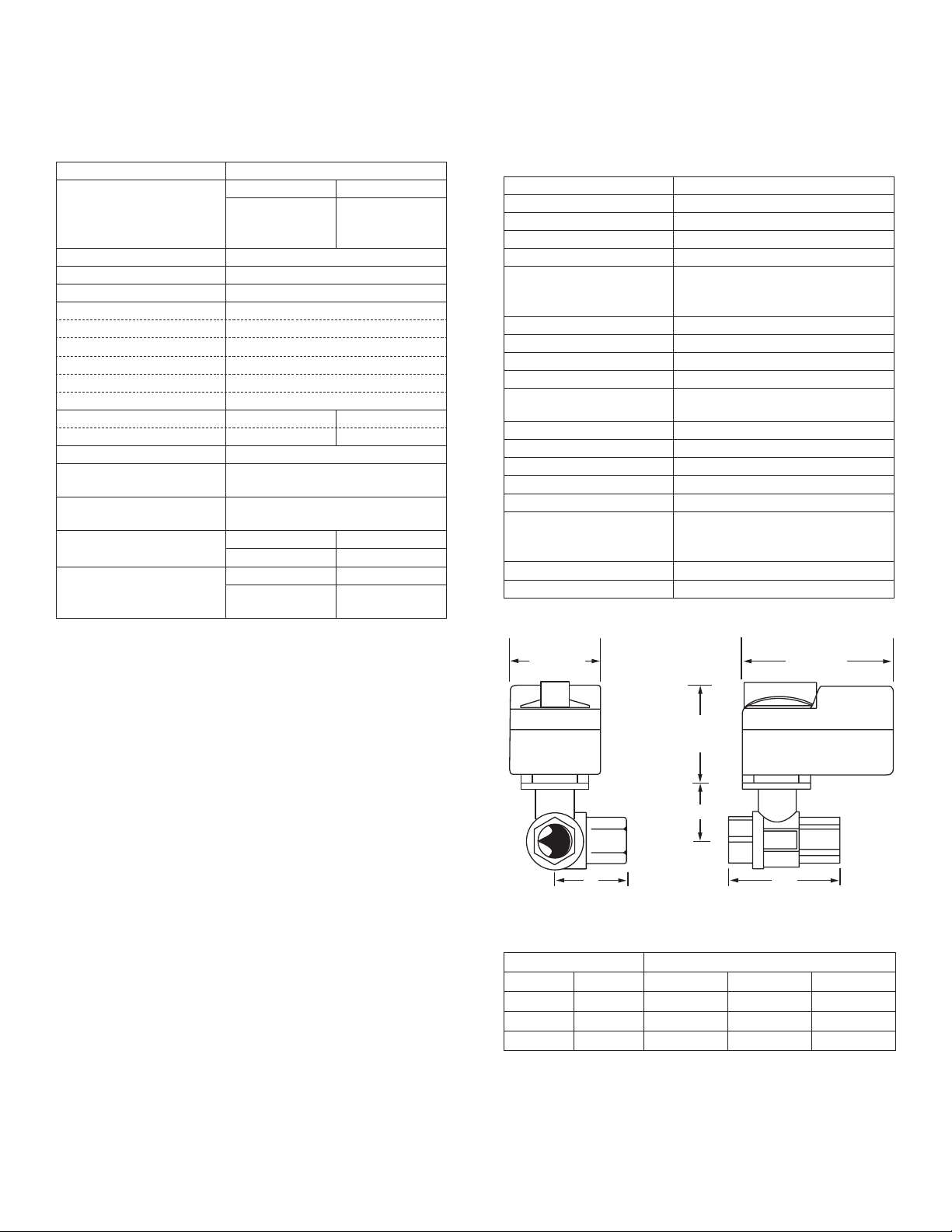
Table K4: Three-way Technical Data
Service Chilled or hot water, 60% glycol
A-port B-port
Flow characteristic
Equal percentage
Action 90° rotation
Sizes ½”, ¾”, 1”, 1¼”, 1½”, 2”
Type of end tting NPT female ends
Materials
Body Forged brass, nickel plated
Ball and stem Stainless steel
Seats PTFE
Characterizing disc Tefzel
®
Packing 2 EPDM O-rings, lubricated
Body pressure rating 600 PSI 400 PSI
½”–1” 1¼”–2”
Media temperature range 0°F to 212°F [−18°C to 100°C]
Close off pressure – 200
PSI
Maximum differential pressure (∆P)
Leakage
½”–2”
30 PSI for typical applications
A to AB B to AB
0% <2%
A-port B-port
Cv rating
See product chart
for values
Modied for constant common
port ow
70% of A to AB
Cv
Table K5: Indoor Three-way Valve Actuator Technical and
Dimensional Data (2 to 5 tons)
Control On/off, oating point
Nominal voltage 24 VAC 50/60 Hz
Nominal voltage range 19.2–28.8 VAC
Power consumption 1 W
Transformer sizing 1 VA (Class 2 power source)
Screw terminals accessible after
Electrical connection
Input impedance 0.36kΩ
Angle of rotation 90°
Position indication Integrated into handle
Manual override Push down handle
Running time
Humidity 5–95% non-condensing
Ambient temperature −22° to 122°F [−30°C to 50°C]
Storage temperature −40°F to 176°F [−40°C to 80°C]
Housing NEMA 1/IP40
Housing rating UL94-5V (B)
Agency listing*
Noise level Max. 35 db (A)
Quality standard ISO 9001
*Rated impulse voltage 330V, control pollution degree 2, type of action 1
removal of small cover (3 feet, 10
feet, 16 feet cables optional)
90 seconds at 60 Hz, 108 seconds
at 50 Hz
cULusa ac. to UL60730-1A/-2- 14,
CAN/CSA E60730-1, CSA C22.2
No. 24-93, CE acc. to 89/336/EEC
2.50”
[63.5 mm]
2.82”
[71.6 mm]
B
C
3.25”
[82.6 mm]
A
Figure K1: Indoor three-way valve actuator (2 to 5 tons)
Table 4: Indoor Three-way Valve Dimensions (2 to 5 tons)
Value Nominal Size Dimensions (Inches [mm])
Inches DN [mm] A B C
½” 15 mm 2.41” [61.1] 1.39” [35.2] 1.20” [30.6]
½” 15 mm 2.38” [60.4] 1.72” [43.7] 1.26” [32.1]
¾” 20 mm 2.73” [69.3] 1.81” [45.9] 1.45” [36.8]
MAMM-VHC-IOM-1A (JANUARY 2013)
41
Page 42
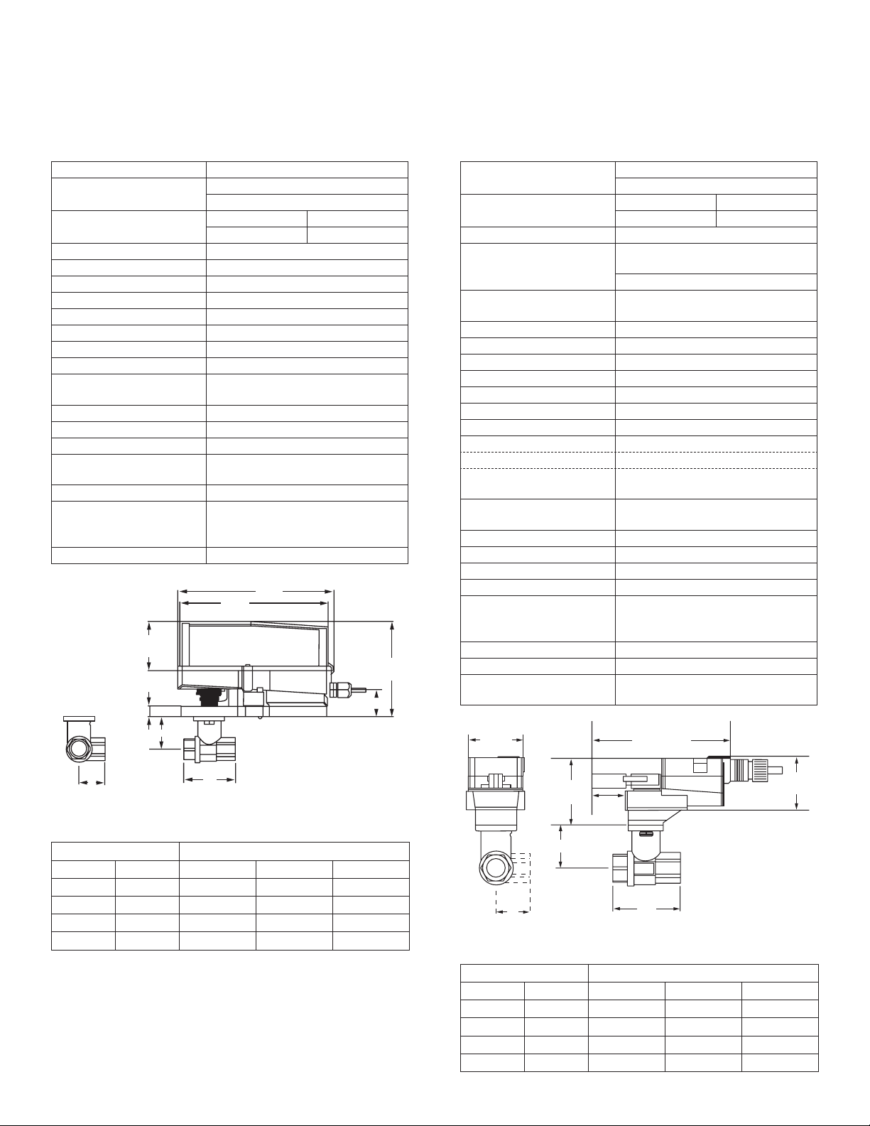
Table K6: Outdoor Three-way Valve Actuator Technical
C
and Dimensional Data (2 to 5 tons)
Control 2–10 VDC, 4–20 mA
Power supply
Power consumption
Transformer sizing 5 VA (Class 2 power source)
Electrical connection Screw terminal (for 26–14 GA wire)
Overload protection Electronic throughout 0° to 95° rotation
Input impedance 100 kΩ [0.1 mA], 500Ω
Angle of rotation 90°, adjustable with mechanical stop
Direction of rotation Reversible with switch
Position indication Visual pointer
Manual override External push button
Running time
Humidity 100% RH
Ambient temperature −22°F to 122°F [−30°C to 50°C]
Storage temperature −40°F to 176°F [−40°C to 80°C]
Housing type
Housing material Polypropylene
Agency listings
Quality standard ISO 9001
2.99”
[76 mm]
0.62” [16 mm]
B
24 VAC ± 20% 50/60 Hz
24 VDC ± 10%
Running Holding
2.5 W 0.4 W
95 seconds constant independent
of load
UL Type 4X/NEMA 4X/IP66 and
IP67
cULus acc. to UL 60730-1A/- 2-14,
CAN/CSA E60730-1, CSA C22.2
No. 24-93, CE acc. to 89/336/EEC
9.76”
[248 mm]
9.21”
[234 mm]
5.28”
[134 mm]
1.0”
[25.5 mm]
Table K2: Indoor Three-way Valve Actuator Technical and
Dimensional Data (6 to 8 tons)
Power supply
Power consumption
Transformer sizing
Electrical connection
Overload protection
Operating range Y
Feedback output U
Input impedance
Angle of rotation
Direction of rotation
Position of indication
Manual override
Running time
LRB24-SR
LRX24-SR
Humidity
Ambient temperature
Storage temperature
Housing
Housing material
Agency listings
Noise level
Quality standard
Electrical connection
2.6”
[66 mm]
24 VAC ± 20% 50/60 Hz
24 VDC ± 10%
Running Holding
1.5 W 0.4 W
3 VA (Class 2 power source)
½” conduit connector 18 GA, plenum rated cable 3 feet [1 m]
_3 ft [1 m] _10 ft [3 m] _16 ft [5 m]
Electronic throughout 0° to 95°
rotation
2–10 VDC, 4–20 mA
1–10 VDC, max. 0.5 mA
100Ω [0.1 mA], 500Ω
90° adjustable with mechanical stop
Reversible with protected switch
Handle
External push button
Constant independent of load
95 seconds
_150 sec. _95 sec. _60 sec.
_45 sec. _35 sec.
5% to 95% RH non-condensing (EN
60760-1)
−22°F to 122°F [−30°C to 50°C]
−40°F to 176°F [−40°C to 80°C]
NEMA 2/IP54
UL94-5VA
cULus acc. to UL60730-1A/-2- 14,
CAN/CSA E60730-1, CSA C22.2
No. 24-93, CE acc. to 9/336/EEC
<35 db (A)
ISO 9001
Screw terminal (for 26–14 GA wire)
protected (NEMA 2/IP20)
7.97” [200 mm]
C
A
Figure K2: Outdoor three-way valve actuator (2 to 5 tons)
Table K1: Outdoor Three-way Valve Dimensions (2 to 5 tons)
Value Nominal Size Dimensions (Inches [mm])
Inches DN [mm] A B C
½” 15 mm 2.41” [61.1] 1.39” [35.2] 1.20” [30.6]
½” 15 mm 2.38” [60.4] 1.72” [43.7] 1.26” [32.1]
¾” 20 mm 2.73” [69.3] 1.81” [45.9] 1.45” [36.8]
1” 25 mm 3.09” [78.4] 1.81” [45.9] 1.56” [39.8]
MAMM-VHC-IOM-1A (JANUARY 2013)
3.22”
[82 mm]
B
1.69”
[42 mm]
A
[59.4 mm]
Figure K3: Indoor three-way valve actuator (6 to 8 tons)
Table K3: Indoor Three-way Valve Dimensions (6 to 8 tons)
Value Nominal Size Dimensions (Inches [mm])
Inches DN [mm] A B C
½” 15 mm 2.41” [61.1] 1.39” [35.2] 1.20” [30.6]
½” 15 mm 2.38” [60.4] 1.72” [43.7] 1.26” [32.1]
¾” 20 mm 2.73” [69.3] 1.81” [45.9] 1.45” [36.8]
1” 25 mm 3.09” [78.4] 1.81” [45.9] 1.56” [39.8]
2.34”
42
Page 43
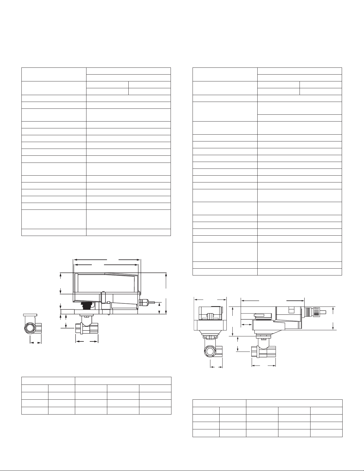
[134 mm]
Table K4: Outdoor Three-way Valve Actuator Technical
and Dimensional Data (6 to 8 tons)
Power supply
Power consumption
Transformer sizing 5 VA (Class 2 power source)
Electrical connection Screw terminal (for 26–14 GA wire)
Overload protection
Operating range Y 2–10 VDC, 4–20 mA
Input impedance 600Ω
Angle of rotation 90° adjustable with mechanical stop
Direction of rotation Reversible with switch
Position indication Visual pointer
Manual override External push button
Running time
Humidity 100% RH
Ambient temperature −22°F to 122°F [−30°C to 50°C]
Storage temperature −40°F to 176°F [−40°C to 80°C]
Housing type UL Type 4X/NEMA 4X/IP66 & IP67
Housing material Polypropylene
Agency listings†
Quality standard ISO 9001
† Rated impulse voltage 800V, type of action 1, control population
degree 3.
2.99”
[76 mm]
0.62” [16 mm]
B
C
24 VAC ± 20% 50/60 Hz
24 VDC ± 10%
Running Holding
2.5 W 0.4 W
Electronic throughout 0° to 95°
rotation
95 seconds constant independent
of load
cULus acc. to UL60730-1A/-2-
14,CAN/CSA E60730-1, CSA C22.2
No. 24-93, CE acc. to 89/336/EEC
9.76”
[248 mm]
9.21”
[234 mm]
1.0”
[25.5 mm]
A
Figure K4: Outdoor three-way valve actuator (6 to 8 tons)
5.28”
Table K6: Indoor Three-way Valve Actuator Technical and
Dimensional Data (10 to 21 tons)
Power supply
Power consumption
Transformer sizing 3 VA (Class 2 power source)
Electrical connection
Overload protection
Operating range Y 2–10 VDC, 4–20 mA
Feedback output U 1–10 VDC, max. 0.5 mA
Input impedance 100Ω [0.1 mA], 500Ω
Angle of rotation 90° adjustable with mechanical stop
Torque 180 in-lb [20 Nm]
Direction of rotation Reversible with switch
Position indication Handle
Manual override External push button
Running time
Humidity
Ambient temperature −22°F to 122°F [−30°C to 50°C]
Storage temperature −40°F to 176°F [−40°C to 80°C]
Housing NEMA 2/IP54
Housing material UL94-5VA
Agency listings†
Noise level <45 db (A)
Quality standard ISO 9001
† Rated impulse voltage 800V, control pollution degree 3, type of action1
(1.B for -S models)
3.46”
[88 mm]
3.3”
[84 mm]
B
24 VAC ± 20% 50/60 Hz
24 VDC ± 10%
Running Holding
2.5 W 0.4 W
½” conduit connector 18 GA plenum rated cable
_3 ft [1 m] _10 ft [3 m] _16 ft [5 m]
Electronic throughout 0° to 95°
rotation
95 seconds constant independent
of load
5% to 95% RH non-condensing
(EN 60730-1)
cULus acc. to UL60730-1A/-214,CAN/CSA E60730-1, CSA C22.2
No. 24-93, CE acc. to 89/336/EEC
8.5” [216 mm]
1.35”
[35 mm]
2.49”
[63.4 mm]
Table K5: Outdoor Three-way Valve Dimensions
(6 to 8 tons)
Value Nominal Size Dimensions (Inches [mm])
Inches DN [mm] A B C
1¼” 32 mm 3.96” [100.6] 2.21” [56.2] 2.14” [54.3]
1½” 40 mm 4.39” [111.6] 2.45” [62.2] 2.33” [59.1]
2” 50 mm 4.90” [124.5] 2.68” [68.0] 2.60” [66.0]
MAMM-VHC-IOM-1A (JANUARY 2013)
C
A
Figure K5: Indoor three-way valve actuator (10 to 21 tons)
Table K7: Indoor Three-way Valve Dimensions (10 to 21
tons)
Value Nominal Size Dimensions (Inches [mm])
Inches DN [mm] A B C
1¼” 32 mm 3.96” [100.6] 2.21” [56.2] 2.14” [54.3]
1½” 40 mm 4.39” [111.6] 2.45” [62.2] 2.33” [59.1]
2” 50 mm 4.90” [124.5] 2.68” [68.0] 2.60” [66.0]
43
Page 44
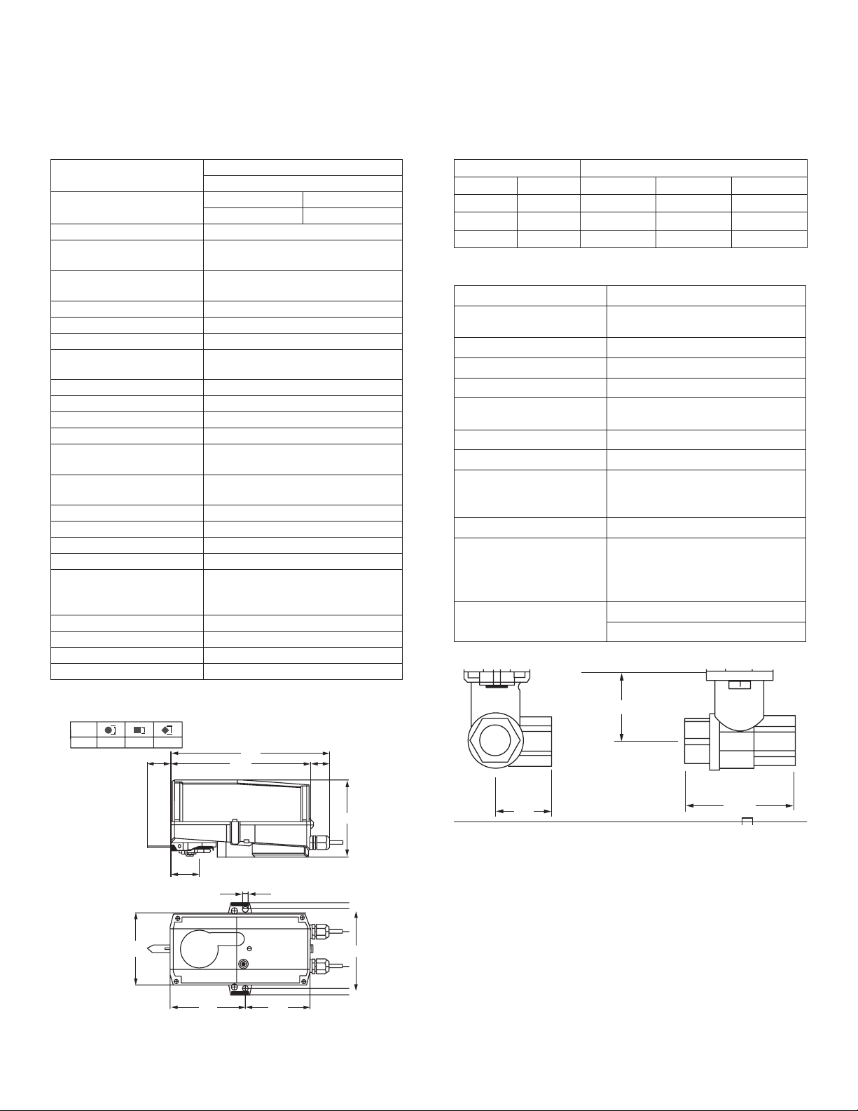
Table K8: Outdoor Three-way Valve Actuator Technical
and Dimensional Data (10 to 21 tons)
Power supply
Power consumption
Transformer sizing 5 VA (Class 2 power source)
Electrical connection
Overload protection
Operating range Y 2–10 VDC, 4–20 mA
Feedback output U 1–10 VDC, max. 0.5 mA
Input impedance 100Ω [0.1 mA], 500Ω
Angle of rotation
Torque 160 in-lb [16 Nm]
Direction of rotation Reversible with switch
Position indication Pointer
Manual override External push button
Running time
Humidity
Ambient temperature −22°F to 122°F [−30°C to 50°C]
Storage temperature −40°F to 176°F [−40°C to 80°C]
Housing IP66/67 UL Type 4X, NEMA 4X
Housing material UL94-5VA
Agency listings†
Noise level <45 db (A)
Servicing Maintenance free
Quality standard ISO 9001
Weight 3.3 lbs [1.5 kg]
† Rated impulse voltage 800V, type of action 1, control pollution degree 3
24 VAC ± 20% 50/60 Hz
24 VDC ± 10%
Running Holding
2.5 W 0.4 W
Screw termianl (for 26–14 GA wire)
½” conduit connector
Electronic throughout 0° to 95°
rotation
Max 95° adjustable with mechani-
cal stop
95 seconds constant independent
of load
5% to 95% RH non-condensing
(EN 60730-1)
cULus acc. to UL60730-1A/-2-
14,CAN/CSA E60730-1, CSA C22.2
No. 24-93, CE acc. to 89/336/EEC
Table K9: Outdoor Three-way Valve Dimensions
(10 to 21 tons)
Value Nominal Size Dimensions (Inches [mm])
Inches DN [mm] A B C
1¼” 32 mm 3.96” [100.6] 2.21” [56.2] 2.14” [54.3]
1½” 40 mm 4.39” [111.6] 2.45” [62.2] 2.33” [59.1]
2” 50 mm 4.90” [124.5] 2.68” [68.0] 2.60” [66.0]
Table K10: Actuator Specications
Torque 162 in-lbs [18 Nm]
Angle of rotation
95° (adjustable with mechanical
stops)
Fits shaft diameter 9/16”...3/4”
Manual override External push button
Direction of rotation External switch
Dimensions
10.66” x 5.28” x 4.88”
[271 x 134 x 124 mm]
Electrical connection Terminal strip
Overload connection Electronic throughout rotation
Add on: 1 or 2 SPDT, 3A (0.5A
Auxiliary switch(es)
inductive) at 250V one switch
adjustable 25° to 85°
Housing specications NEMA 4/4X, IP66/IP67
cULus according to UL 30730-
Agency listings
1A/- 2-14, CAN/CSA E607301:02, CE according to 2004/108/
EC and 2006/95/EC
Control shaft length
Minimum ¾”
Maximum 2¼”
B
AM..N4
1.52”
2.01”
4.88”
5.15”
9.56”
10.66”
1.10”
5.28”
0.21”
5.52”
4.41”
9/10”...3/4”
3/8”...9/10”
9/10”...3/4”
Figure K6: Outdoor three-way valve actuator (10 to 21 tons)
MAMM-VHC-IOM-1A (JANUARY 2013)
C
Figure K7: Actuator
A
44
Page 45
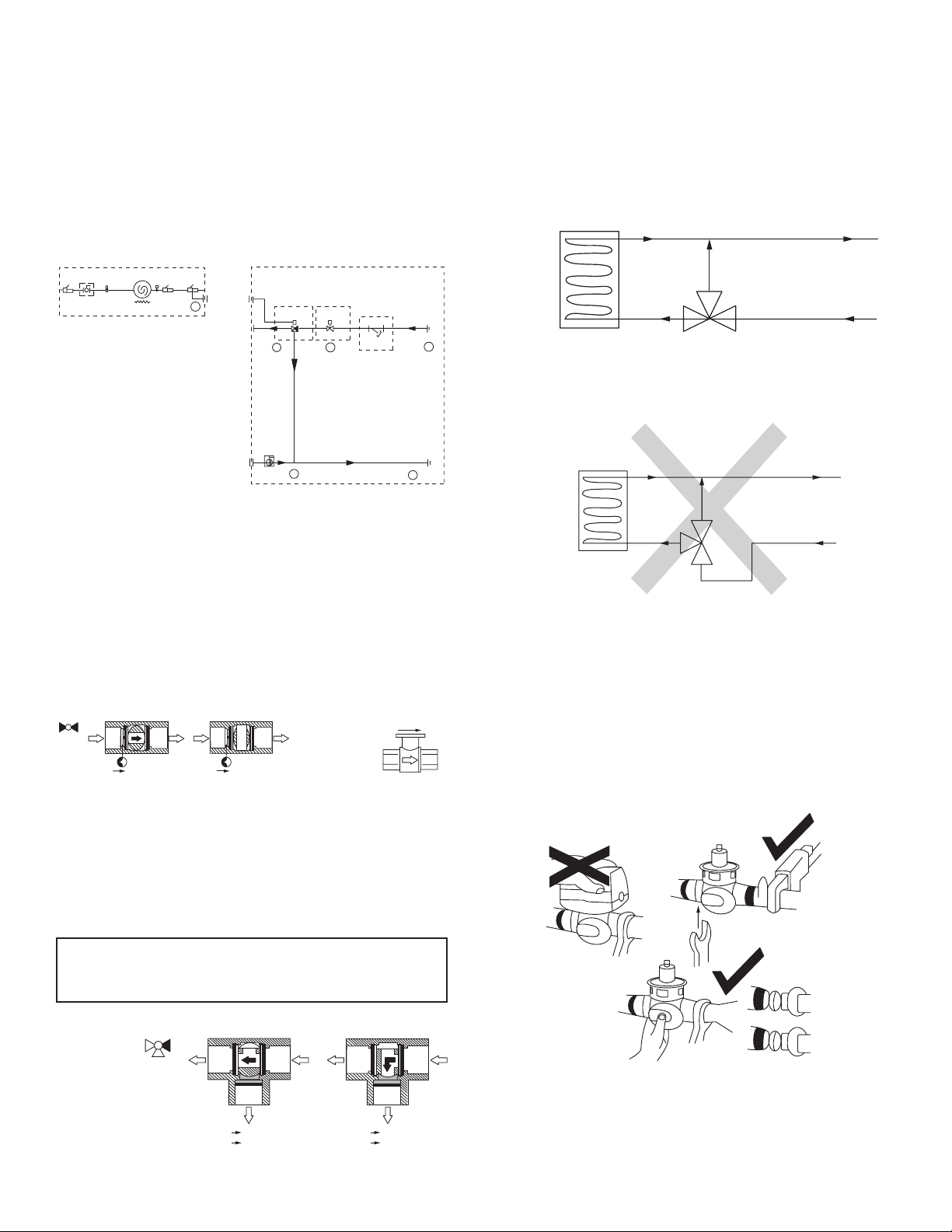
Water Valve Piping Arrangement
option
ABAAAB
A AB 0%AB 100%
Two-way valves
should be installed
with the disc
upstream.
Flow direction
AAB
Belimo
A
AA
%A
It is important to follow the proper piping arrangement for
both two-way and three-way water valves. Incorrect piping
arrangements will damage the unit. The eld piping schematic is illustrated below.
Correct Piping
1 input, 2 outputs
Return
Refrigerant components
Access valve
P
Switch low optional
pressure valve kit
Pressure transducer factory
mounted at compressor
discharge port
Scroll compressor
Access valves
Crank case heater
P
Switch high
pressure
Pressure
transducer
P
T
Unit water inlet
Unit water outlet
Head pressure
control valve
option
Modulating
three-way valve
C
Flow
switch
H
J
On/off valve
accessory
Motorized valve
water shut-off
B
B
Field mounted
Strainer
Water inlet
Water inlet
K
A
Figure K8: Water valve piping arrangement
For Two-way Valve
Two-way valves should be installed in accordance to the
arrow direction marked on the valve body for the water inlet
or supply line. Two-way valves should be installed with the
disc upstream. If installed with disc downstream, ow curve
will be deeper. If installed “backwards” it is not necessary to
remove and change. No damage or control problems will
occur.
Figure K9: Two-way valve arrangement
Coil
B
Supply
A
AB
Figure K11: Correct three-way diverting valve piping
Incorrect Piping
1 input, 2 outputs
Return
Coil
A
Supply
B
AB
Figure K12: Incorrect three-way diverting valve piping
Valve and Actuator Installation
Mount the valve directly in the pipe where the assembly will
not block the system vent or other components. Do not grip
the actuator while making and tightening up plumbing connections. Either hold valve body in your hand or attach adjustable wrench across the hexagonal or at faces on the
valve body. If assembling valve train on bench, take care
For Three-way Valve
Three-way valves must be installed with the ‘AB’ marked
or common port to the supply water line, the ‘A’ marked
or control port to the coil and the ‘B’ marked, ‘Bypass’ or
middle port to the return water line.
CAUTION
If the valve is piped incorrectly, it must be re-piped as it
may restrict ow and cause damage to the unit.
Diverting
AAB
The A-port must
be piped to the coil
to maintain proper
control.
Figure K10: Three-way valve arrangement
MAMM-VHC-IOM-1A (JANUARY 2013)
B
A
AB 100
B
B
A
B 0%
B
AB 70%AB 0%
B
Figure K13: Valve installation
not to deform the body with a vise.
45
Page 46
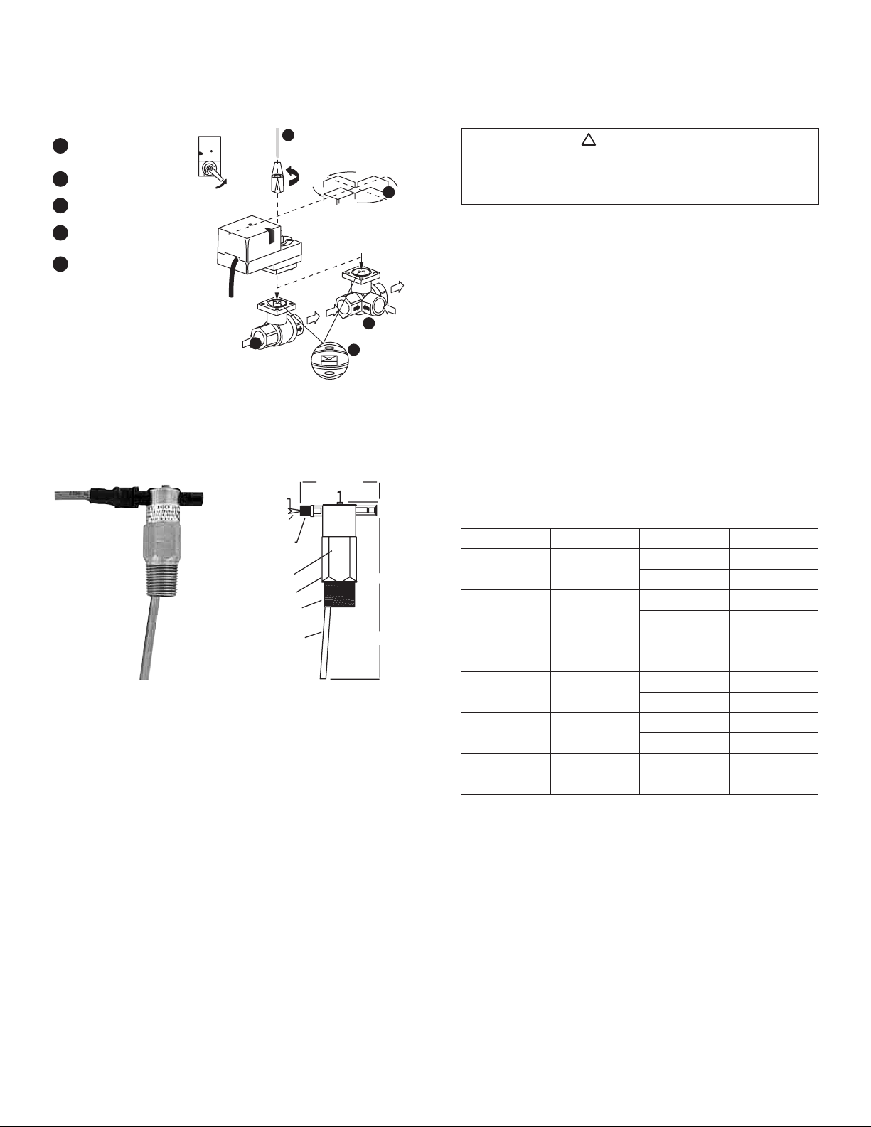
A
A-AB = 100%
!
2-7/16” [62 mm]
3
1
A-AB = 100%
CCW
4 x 90°
2
AB
5
B
4
B-AB = 0%
A
AB
One screw attaches
1
actuator to valve
Four actuator mounting
2
positions
3
Two-way flow pattern
Three-way flow pattern
4
(mixing shown)
Top of valve stem indicates
5
direction of flow
(Flow A to AB shown)
Note: For diverting flow, flow
enters in AB and diverts
to A and B ports.
CCW
Figure K14: Valve and actuator assembly and installation
Water Flow Switch
Flow Switch Dimensions
¼ (6) travel to
normally closed
position
(2) 22 AWG Leadwires
18 (460) long
1/8 NPT – switch shown
in normally open position
Lower body
7/8 hex
½ NPTM
Figure K15: Valve and actuator assembly and installation
Flow Switch Installation
The ow switch must be externally eld mounted in the
leaving or outlet water line. Before installation, the ow
switch vane must be trimmed for the size of piping being
used. A full size, trimmable stainless steel vane is provided
with a removable laminate template. This template is calibrated for brass or ductile iron reducing tee and forged
steel straight tee/brushing combination which allows for
eld installation in pipeline from ½” to 2” diameter. See
Table K11 for approximate actuation and deactivation values.
1. Carefully unpack the ow switch and remove any
packing material from the lower housing. Trim the
vane at the appropriate mark for the size of piping
being used.
2¼” [57 mm]
1” [25 mm]
2-7/8” [73 mm]
Vane
WARNING
Mechanical shock or vibration can cause permanent
damage to the switch. Avoid dropping the unit on hard
surfaces.
2. Apply thread tape or sealant to the ½” male NPT
mounting threads and install the ow switch in the system piping with the arrow on the side pointing in the
direction of ow.
3. The ow switch must be eld wired to the standard
eld wiring (FW) terminal strip as per wiring schematic
for 24 VAC.
4. Avoid exceeding any of the maximum electrical ratings
which can lead to failure.
5. After installation, set the switch action to normally
open or normally closed. To change the switching
from normally open to normally closed, loosen, but
do not remove the two screws on the top cap. Slide
the reed switch assembly to expose the switch action selected. Tighten screws when adjustment is
Table K11: Flow Switch Performance Data Table
Cold Water Flow Rates –
Approximate Actuation/Deactuation
Pipe Trim NO NC
½” L
¾” J
1” H
1¼” E
1½” C
2” Full
GPM upper, LPM lower
complete.
2.6/2.3 2.6/2.5
9.8/8.7 9.8/9.5
3.1/2.7 3.1/2.8
11.7/10.2 11.7/10.6
4.8/4.5 4.8/4.4
18.2/17.0 18.2/16.7
6.2/5.6 6.1/5.6
23.5/21.2 23.1/21.2
8.2/7.7 8.2/7.7
31.0/29.1 31.0/29.1
9.5/9.1 9.5/9.0
36.0/34.4 36.0/34.1
MAMM-VHC-IOM-1A (JANUARY 2013)
46
Page 47

Appendix L: Enthalpy Wheel Pressure Drop vs. Flow Formulae and
Curves
Enthalpy Wheel Pressure Drop vs. Flow
Formula
Flow in cfm = pressure drop measured in ” w.c. / pressure
drop coefcient based on enthalpy wheel size
Table L1: Enthalpy Wheel Pressure Drop Coefcient
Enthalpy Wheel Size
(diameter x depth in inches)
Pressure Drop
Coefcient
36 x 4 0.00029551
36 x 6 0.00032675
36 x 8 0.00038283
42 x 4 0.00021504
42 x 6 0.00023397
42 x 8 0.00027220
50 x 4 0.00014783
50 x 6 0.00016034
50 x 8 0.00018639
Enthalpy Wheel Pressure Drop vs. cfm
Curves (based on wheel diameter x depth
(inches))
1.0
0.9
0.8
0.7
0.6
0.5
0.4
Pressure Drop [in. w.g.]
0.3
0.2
0.1
0.0
0 500 1,000 1,500 2,000 2,500 3,000
Airflow [cfm]
Figure L1: Pressure drop – 36” enthalpy wheel diameter
36” x 8” (High)
36”x 6” (Standard)
36” x 4” (Medium)
1.0
0.9
0.8
0.7
0.6
0.5
0.4
Pressure Drop [in. w.g.]
0.3
0.2
0.1
0.0
0 500 1,000 1,500 2,000 2,500 3,000 3,500 4,000
Airflow [cfm]
42” x 8” (High)
42”x 6” (Standard)
42” x 4” (Medium)
Figure L2: Pressure drop – 42” enthalpy wheel diameter
1.1
1.0
0.9
0.8
0.7
0.6
0.5
0.4
Pressure Drop [in. w.g.]
0.3
0.2
0.1
0.0
0 1,000 2,000 3,000 5,000 6,0004,000
Airflow [cfm]
50” x 8” (High)
50”x 6” (Standard)
50” x 4” (Medium)
Figure L3: Pressure drop – 50” enthalpy wheel diameter
MAMM-VHC-IOM-1A (JANUARY 2013)
47
Page 48

[email protected]
www.mammoth-inc.com
Mammoth, Inc. has a policy of continuous improvement and reserves
the right to change design and specications without notice.
©2013 Mammoth, Inc.
MAMM-VHC-IOM-1A
January 2013
 Loading...