

Page 1
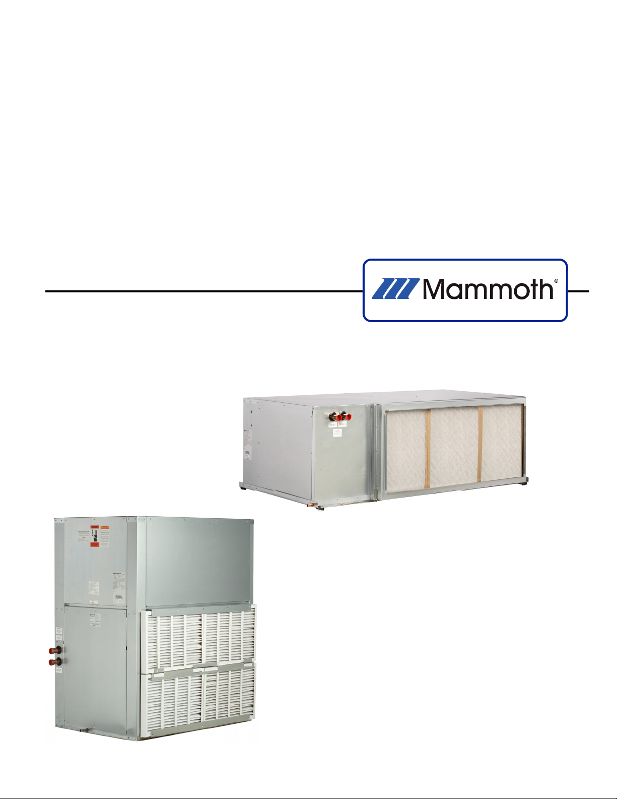
Multiple Circuit Horizontal and Vertical
Water Source Heat Pumps With R-410A
Installation, Operation and Maintenance Manual
Sizes: 084 to 144 — Horizontal
084 to 288 — Vertical
Model: M Vintage
MAMM-WSHP-IOM-1MA (November 2011)
P/N 71144916
Page 2
Table of Contents
Model Nomenclature ················································································································ 3
Transportation and Storage ···································································································· 3
Installation ································································································································ 4
Unit Location ···························································································································· 5
Ductwork and Attenuation ······································································································· 6
Ventilation Air ··························································································································· 6
Piping ········································································································································ 7
Cleaning and Flushing ············································································································· 8
Fan Wall Assembly ··················································································································· 9
Start-up···································································································································· 10
Operating Limits ····················································································································· 11
DDC Controls ·························································································································· 12
I/O’s ········································································································································ 13
Keypad ···································································································································· 14
General Maintenance ············································································································· 15
VFD application parameters ·································································································· 16
Troubleshooting ····················································································································· 17
Performance Troubleshooting ····························································································· 18
Unit check-out sheet ············································································································· 19
M Vintage Vertical
Size 084 to 288
MAMM-WSHP-IOM-1MA (November 2011)
M Vintage Horizontal
Size 084 to 144
2
Page 3

Model Nomenclature
F -084- V- H- M
Voltage
BTU/hr Cooling
Unit Type Temperature Range Vintage
F = 208-230/60/3
G = 460/60/3
J = 380-415/50/3
K = 575/60/3
Illustrations cover the general appearance of Mammoth products at the time of publication and Mammoth, Inc. reserves the right to make changes
in design and construction at anytime without notice.
084 = 84,000
096 = 96,000
120 = 120,000
144 = 144,000
168 = 168,000
192= 192,000
240 = 240,000
288 = 288,000
V = Vertical H = Standard Range
H= Horizontal L = Low Temp Operation
“Mammoth” is a registered trademark of Mammoth, Inc.
©Mammoth, Inc. 2011. All rights reserved throughout the world.
Transportation and Storage
Upon receipt of the equipment, check for visible damage. Make a notation on the shipper’s delivery ticket
before signing. If there is any evidence of rough handling, immediately check for concealed damage. If any
damage is found, notify the carrier within 48 hours to
establish your claim and request their inspection and a
report. Then contact the Mammoth Service department
at (952) 358-6618 or [email protected]
for a warranty claim number.
MAMM-WSHP-IOM-1MA (November 2011)
Do not stand or transport the unit on end. In the
event that elevator transfer makes up-ended positioning unavoidable, absolutely ensure that the unit is in
the normal upright position for at least 24 hours before
operating.
Temporary storage at the job site must be indoors,
completely sheltered from rain, snow, etc. High or low
temperatures naturally associated with weather patterns will not harm units. Excessively high temperatures, 140°F (60°C) and higher, may deteriorate certain
plastic materials and cause permanent damage.
3
Page 4
Installation
General
IMPORTANT:
Mammoth water source heat pumps should be installed only by qualified personnel, experienced in the
installation of this equipment and related systems.
Read these instructions carefully before unpacking,
installing and operating this unit
1. To prevent damage, this equipment should not be
operated for supplementary heating and cooling
during the construction period.
2. Inspect the unit for any specific tagging numbers
indicated by the factory per a request from the installing contractor.
3. Check the unit nameplate for the size and voltage
rating and confirm against the plans that the unit is
being installed in the correct location.
4. Verify the installation location with the piping, sheet
metal and electrical contractors prior to installation
5. Verify all clearances are available for the unit prior
to installation.
6. Note the location and routing of water piping, condensate drain piping, and electrical wiring. The locations of these items are clearly marked on submittal drawings.
7. Mammoth recommends the unit be covered during
construction to protect components from dust and
other harmful material. This is critical while spraying fireproofing material on bar joists, sandblasting,
NOTE:
Check the unit name plate for correct voltage with the
plans before installing the equipment. Make sure all
electrical ground connections are made in accordance
with local code.
MAMM-WSHP-IOM-1MA (November 2011)
4
Page 5
Unit Location
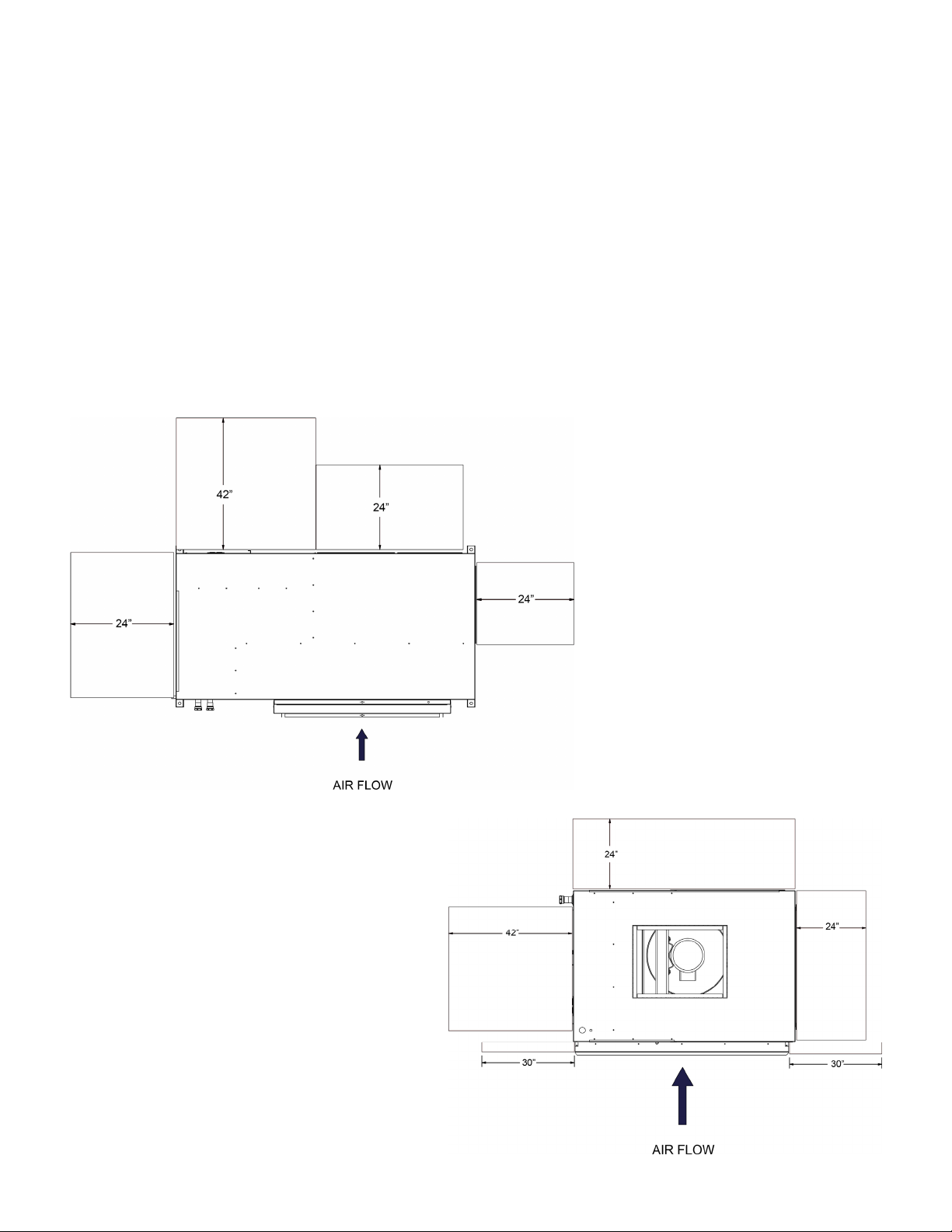
Locate the unit in an area that allows for easy removal
of the filter and access panels. The diagrams to the
right show minimum suggested clearances. Any additional clearances would be beneficial, but not always
necessary. Units need to be accessed from three
sides: two panels for the two panels for the blower, two
electrical access doors and one for the compressor
compartment.
Horizontal Service Clearances
The requirements on any specific unit may increase or
be reduced depending on several factors such as
maintenance requirements and mechanical or electrical
installation codes. Horizontal unit filters are removed
from the bottom with an option for side removal. Vertical unit filters slide out of the left or right side (quadcircuit units must be removed from each side). If return
air is not ducted, enough clearance will required to provide for adequate airflow.
MAMM-WSHP-IOM-1MA (November 2011)
Vertical Service Clearances
5
Page 6

Ductwork and Attenuation
Discharge ductwork is normally used with the Mvintage horizontal and vertical multiple circuit units.
Return air ductwork may also be required.
All ductwork should conform to industry standards
of good practice as described in the ASHRAE Systems
Guide.
The discharge duct system will normally consist of
a flexible connector at the unit connection, a transition
piece to the full duct size, a short run of duct,
and elbow with vanes, and a trunk duct teeing into
a branch duct with discharge diffuses. The transition
piece must not have angles totaling more than
30° or severe reduction in airflow performance can
result.
Ventilation Air
Do not connect the full duct size to the unit. Use a
transition piece sized according to the discharge collar
on the unit to get to the full duct size. With metal duct
material, the sides of only the elbow and entire branch
duct should be internally lined with acoustic fibrous
insulation for sound attenuation. Glass fiber duct board
material is more absorbing and may permit omission of
the canvas connector.
The ductwork should be laid out so that there is no
line of sight between the unit discharge and
the distribution diffusers.
Do not use sheet metal screws directly into the unit
cabinet for connection of supply or return air ductwork,
especially return ductwork which can hit the drain pan
or the air coil.
Outside air may be required for ventilation. The
temperature of the ventilation air must be controlled so
that the mixture of outside air and return air entering
the
unit is within application limits. It is typical to close off
the ventilation air system during unoccupied periods
(i.e. night setback).
The ventilation air system is typically a separate
building subsystem with distribution ductwork. Simple
introduction of the outside air into each return air
plenum chamber reasonably close to the unit air inlet is
recommended. Do not duct outside air directly to the
unit inlet. Provide sufficient distance for the thorough
mixing of outside and return air.
.
MAMM-WSHP-IOM-1MA (November 2011)
6
Page 7

Supply Piping
1. All heat pumps should be connected to supply and
return piping in a two-pipe reverse return
configuration. A reverse return system is inherently
self-balancing and requires only trim balancing
where multiple quantities of heat pumps with
different flow and pressure drop characteristics
exist in the same loop. Check for proper water
balance by measuring differential temperature
reading across the water connections. To insure
proper water flow, the differential temperature
should be between 10°F to 14°F for heat pumps in
the cooling mode.
2. The piping may be steel, copper, or PVC. Avoid
dissimilar metal fittings as they may corrode. If the
use of dissimilar metals is unavoidable, use
dielectric isolation at that connection point.
3. Supply and return run-outs usually join the heat
pump via short lengths of high pressure flexible
hose which are sound attenuators for both heat
pump operating noise and hydraulic pumping
noise. One end of the hose should have a swivel
fitting to facilitate removal for service. Hard piping
can also be brought directly to the heat pump. This
option is not recommended since no vibration or
noise attenuation can be accomplished. The hard
piping must have a union to facilitate heat pump
removal.
4. Make sure that threaded fittings are sealed. Teflon
tape can be used to provide a tight seal.
5. Supply and return shutoff valves are required at
each heat pump. The return valve is used for
balancing and should have a “memory stop” so that
it can always be closed off but can only be
reopened to the proper position for the flow
required.
6. No heat pump should be connected to the supply
and return piping until the water system has been
cleaned and flushed completely. After the cleaning
and flushing has taken place, the initial connection
should have all valves wide open in preparation for
the water system flushing.
Condensate Piping
1. Condensate piping can be steel, copper, or PVC.
Each unit includes a condensate connection.
2. The condensate disposal piping must be trapped.
Vertical and horizontal units must be externally
trapped. The piping must be pitched away from the
heat pump not less than ¼” per foot. The unit is
supplied with a 1-1/4” male pipe fitting to
accommodate the condensate drain connection.
3. Do not locate any point in the drain system above
the drain connection of any unit.
4. The condensate piping system must be vented at
its highest point.
MAMM-WSHP-IOM-1MA (November 2011)
7
Page 8

Cleaning and Flushing
1. Prior to first operation of the M-Vintage horizontal
and vertical units, the water circulation system
must be cleaned and flushed of all construction dirt
and debris
2. If the M-Vintage horizontal and vertical units are
equipped with water shutoff valves, either electric
or pressure operated, the supply and return runouts must be connected at each heat pump location. This will prevent the introduction of dirt into the
heat pump.
3. Fill the system at the city water makeup connection
with all air vents open. After filling, close all air
vents.
4. The contractor should start the main circulator with
the pressure reducing valve open. Check vents in
sequence to bleed off any trapped air, providing
circulation through all components of the system.
5. While circulating water, the contractor should check
and repair any leaks in the piping. Drains at the
lowest point(s) in the system should be opened for
the initial flush and blow down, making sure city
water fill valves are set to make up water at the
same rate. Check the pressure gauge at the pump
suction and manually adjust the makeup to hold the
same positive steady pressure both before and
after opening the drain valves. Flush should continue for at least two hours, or longer if required,
until the drain water is clear and clean.
6. Shut off supplemental heater (if applicable) and
circulator pump and open all drains and vents to
completely drain down the system. Short circuited
supply and return runouts should now be connected to the heat pump supply and return connections. Do not use sealers at the swivel flare connections of the hoses.
7. Refill the system with clean water. Test the water
using litmus paper for acidity and treat as required
to leave the water slightly alkaline (pH 7.5 to 8.5).
The specified percentage of antifreeze may also be
added at this time. Use commercial grade antifreeze designed for HVAC systems only. Do not
use automotive grade antifreeze.
8. Once the system has been filled with clean water
and antifreeze (if used), precaution should be taken
to protect the system from dirty water conditions.
Dirty water will result in system wide performance
degradation and solids may clog valves, strainers,
flow regulators, etc. Additionally, the heat exchangers may become clogged which reduces compressor service life or causes premature failure.
9. Set the loop water controller heat add setpoint to
70°F and the heat rejection setpoint to 85°F. Supply power to all motors and start the circulation
pumps. After full flow has been established through
all components including the heat rejecter
(regardless of season) and air has been vented
and loop temperatures have been stabilized, each
of the heat pumps will be ready for check, test and
start-up, and water balancing.
MAMM-WSHP-IOM-1MA (November 2011)
8
Page 9
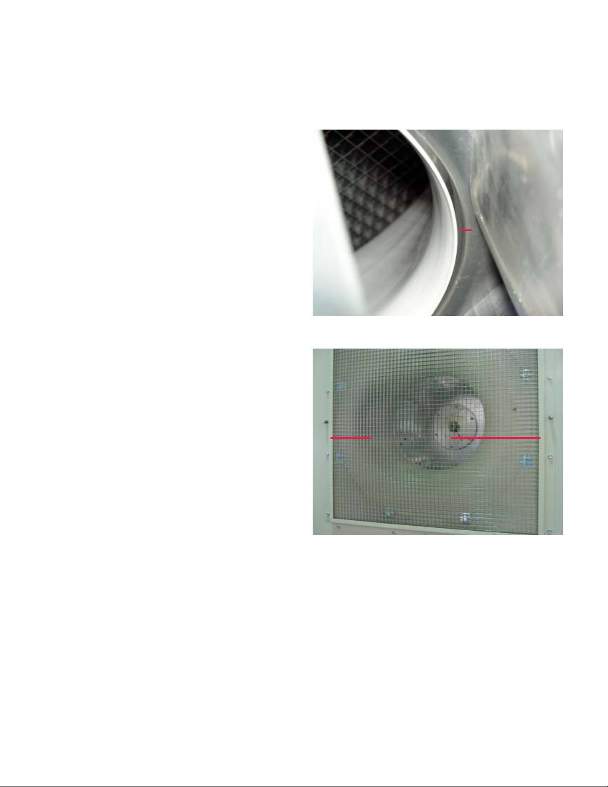
FANWALL TECHNOLOGY® Assembly
Fan / Cone Alignment
1. Temporarily attach the cone to the cell inlet using the
screws and washers provided, or slightly loosen
the screws holding the cone if already installed.
Use a minimum of four screws for this step.
a. Refer to the fan wheel overlap drawings provided to determine where to set the wheel with respect to the cone.
b. Adjust the amount of overlap by moving the motor pedestal forward or backward to line up the
cone with the wheel (wheel/cone overlap is designed to insert the cone 50% of the distance of the
rolled shroud lip on the wheel). Once you have the
wheel approximately located, tighten the ½” pedestal bolts to 90ftlbs.
2. Center the cone in the wheel shroud.
a. The cone alignment can be a tedious process as
there are no tools that effectively work to align the
cone. It is a hands on process to align the cone.
Mammoth cones have a running clearance of
about 1/16" (see Figure 1).
b. Start by loosening the four screws that were
used to hold the cone for the depth alignment. Hold
the cone with one hand and with the other use a
drill to attach a screw to hold the cone in place.
Feel between the wheel inlet shroud and the cone
and set the gap to approximately 1/16" and tighten
the screw in that location (top of the cone is usually
the best place to start). At this point you should be
able to move the cone about that screw location,
adjusting the cone on the left or right until there is
approximately a 1/16" gap.
c. Spin the wheel by hand at this point to check for
any clearance issues. If the wheel spins clear,
tighten the remaining screws on the cone. Check
that the wheel spins clear after tightening each
screw.
3. Attach the inlet airflow straightener using the formed
angle brackets (see Figure 2).
a. Start by loosely installing (don’t tighten screws
all the way) the bottom angle bracket. Set the airflow grid on the angle bracket. Align the side of the
grid with the end of the bracket.
b. Install either vertical angle bracket loosely and
check fit up.
c. Install the two remaining brackets and tighten
(see Figure 2).
Figure 1—FANWALL® cone alignment
TYPICAL FAN-CONE
CLEARANCE
FIGURE 1
Figure 2—Inlet airflow straightener
AIRSTRAIGHTENER
AIR STRAIGHTENER
ANGLE BRACKERS
FIGURE 2
MAMM-WSHP-IOM-1MA (November 2011)
9
Page 10

Start-up
1. Open all valves to full open position and turn on
power to the heat pump.
2. Set room temperature sensor for “Fan Only” operation by selecting “Off” at the system switch and
“On” at the fan switch. If “Auto” fan operation is selected, the fan will cycle with the compressor.
Check for proper air delivery.
3. M-Vintage horizontal and vertical units have time
delays which help protect the compressor(s)
against short cycling. In the cooling mode, after a
few minutes of operation, check the discharge
grilles for cool air delivery. Measure the temperature difference between entering and leaving water.
It should be approximately 1 ½ times greater than
the heating mode temperature difference.
4. In the heating mode, measure the temperature difference between entering and leaving air and entering and leaving water. With entering water of 60°
F to 80°F, leaving water should be 6°F to 12°F
cooler, and the air temperature rise through the MVintage horizontal and vertical units should not exceed 35°F. If the leaving air temperature falls below 35°F, adjust water flow to the unit to >3 gpm/
ton to avoid freeze damage to the unit.
5. Fill the p-trap with water to ensure that negative
pressure does not pull drain gases into the unit.
6. Check the elevation and cleanliness of the condensate line. If the air is too dry for sufficient dehumidification, slowly pour enough water into the condensate pan to ensure proper drainage.
7. If the unit does not operate, check the following
points:
a) Is supply voltage to the M-Vintage horizontal and
vertical units compatible?
b) If the M-Vintage horizontal and vertical units operates but stops after a brief period:
i) Is there proper airflow? Check for dirty filter,
incorrect fan rotation or incorrect ductwork.
ii) Is there proper water flow rate within temperature limits? Check water balancing; backflush unit if dirt clogged.
iii) See troubleshooting guide on page 16 for
more tips.
MAMM-WSHP-IOM-1MA (November 2011)
10
Page 11
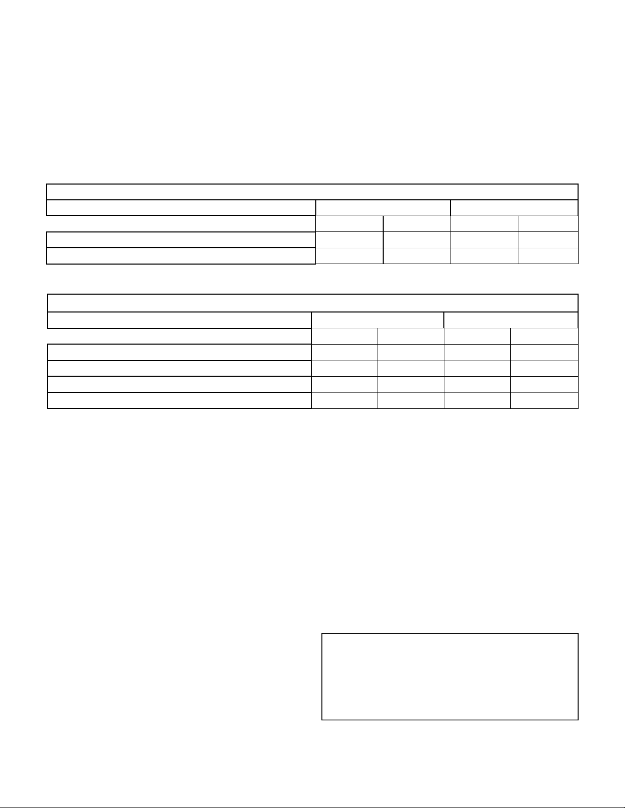
Operating Limits
Environment
This equipment is designed for indoor installation only.
Sheltered locations such as attics, garages, etc., generally will not provide sufficient protection against ex-
Application Limits
WATER TEMPERATURES / Degrees F *
MINIMUM ENTERING WATER TEMPERATURE
MAXIMUM ENTERING WATER TEMPERATURE
* Application limits apply at or above standard flow rates specified for size of unit.
Application Limits
AIRTEMPERATURES/DegreesF*
MINIMUMAMBIENTAIRTEMPERATURE**
MAXIMUMAMBIENTAIRTEMPERATURE**
MINIMUMENTERINGAIRTEMPERATURE
MAXIMUMENTERINGAIR
TEMPERATURE
*Applicationlimitsapplyatorabovestandardflowratesspecifiedforsizeofunit.
**Minimumandmaximumambientconditionsapplytoductedsupplyandreturnunitsonly.
tremes in temperature and/or humidity, and equipment
performance, reliability, and service life may be adversely affected.
Standard range Low Temp Geothermal
COOLING HEATING COOLING HEATING
50˚ 50˚ 40˚ 25˚
110˚ 90˚ 110˚ 90˚
Standardrange LowTempGeothermal
COOLING HEATING COOLING HEATING
50˚ 50˚ 50˚ 50˚
110˚ 110˚ 110˚ 110˚
65˚ 50˚ 65˚ 40˚
100˚ 80˚ 100˚ 80˚
Additional Information For Initial Start-up Only
Standard Range Units
Units are designed to start-up in an ambient
temperature of 50°F (10°C), with entering air at 50°F
(10°C), with entering water at 70°F (21°C), with both air
and water flow rates used in the ISO13256-1 rating
test, for initial start-up in winter.
Note: This is not a normal or continuous operating
condition. It is assumed that such a start-up is for the
purpose of bringing the building space up to occupancy
temperature.
Geothermal Range Units
Geothermal heat pump units are designed to start-up in
an ambient temperature of 50°F (10°C), with entering
air at 40°F (5°C), with entering fluid at 25°F (-4°C), with
both air and water at flow rates used in the ISO 132561 rating test, for initial start-up in winter.
MAMM-WSHP-IOM-1MA (November 2011)
Note: This is not a normal or continuous operating
condition. It is assumed that such a start-up is for the
purpose of bringing the building space up to occupancy
temperature.
Operating voltages
208-230/60/3. . . . . . . . . 197 volts min.; 253 volts max.
460/60/3 . . . . . . . . . . . . 342 volts min.; 418 volts max.
380-415/50/3. . . . . . . . . 342 volts min.; 418 volts max.
575/60/3 . . . . . . . . . . . . 342 volts min.; 418 volts max.
Note:
Voltages listed are to show voltage range. However,
units operating with over- or under-voltage conditions
for extended periods of time will experience premature
component failure. Three phase system imbalance
should not exceed 2%.
11
Page 12
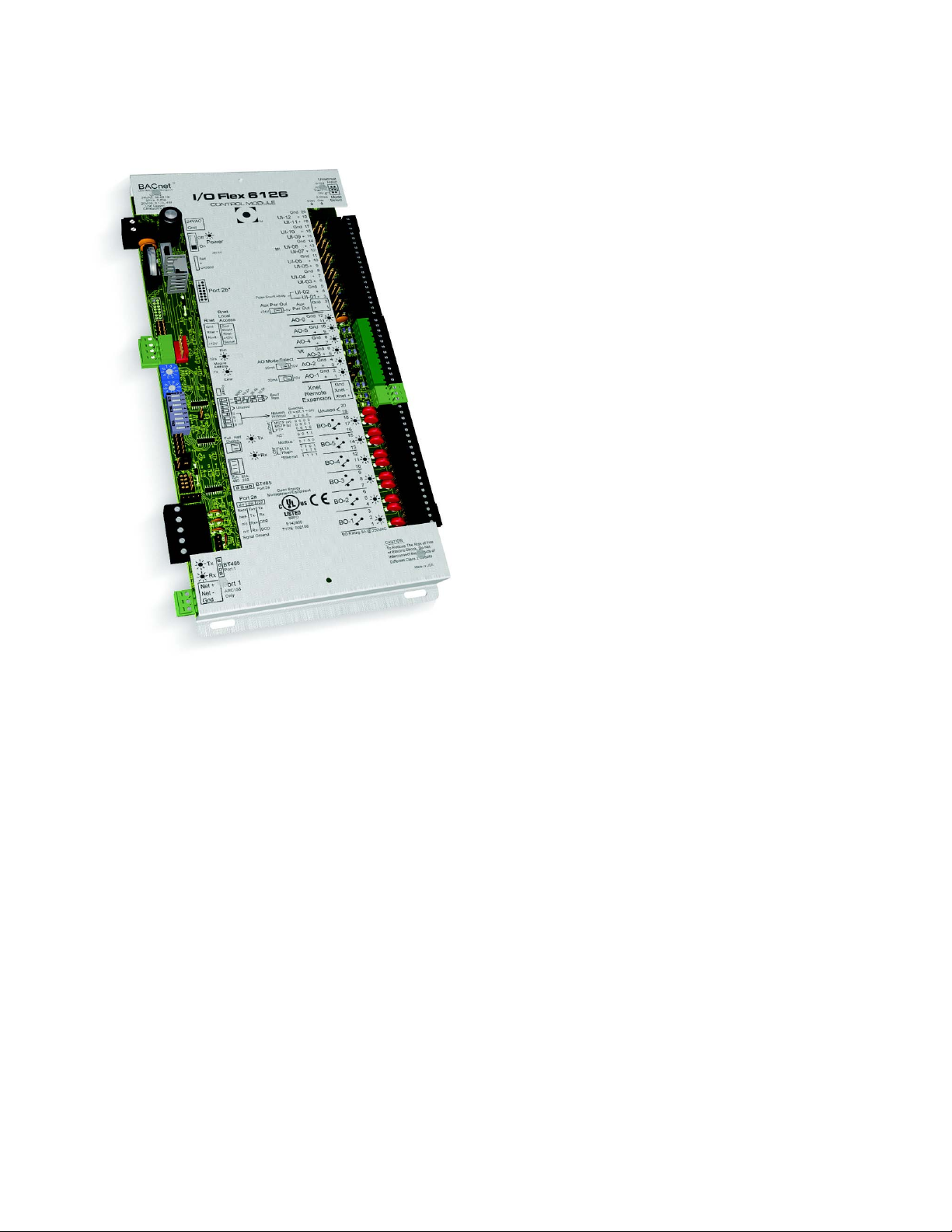
MAMMOTH DDC CONTROLS
I/O Flex 6126
The standard factory-integrated DDC controller provides control flexibility that can be easily customized to
meet any sequence of operation needs. It is fully capable of operating in a 100% stand-alone mode or can
connect to a Building Automation System (BAS) using
any of today’s four leading protocols: BACnet, Modbus,
N2, and Lontalk. The base controller provides ample
input/output capacity, plus support for an expander
board if additional I/O capacity is required.
Key Features and Benefits
6160 I/O points: 6 digital outputs, 12 universal inputs, and 6 analog outputs.
8160 I/O points: 16 universal inputs, 8 digital outputs.
Optional built-in protocol support: BACnet® (ARCNET, MS/TP, and PTP modes), Modbus® (RTU and ASCII
modes supported), N2, or Lontalk®.
Powerful, high-speed 16-bit microprocessor with 1 MB Flash memory and 1 MB of battery-backed RAM
Built-in support through an Rnet port for control’s custom configurable keypad/display unit, BACview6 (4-line by
40 character per line display) for intelligent sensors.
For variable air volume (VAV), constant volume (CAV), and make-up air (MAU) applications.
MAMM-WSHP-IOM-1MA (November 2011)
12
Page 13
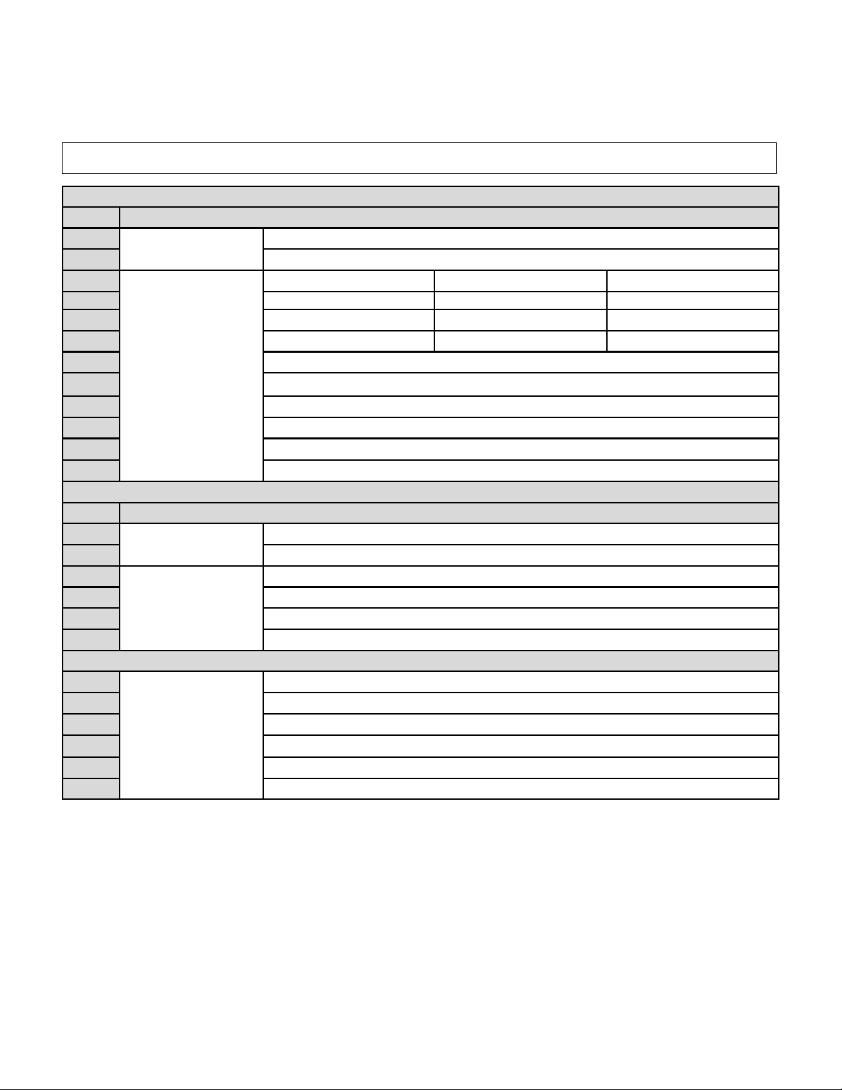
Examples of I/O’s
INPUTS
Point Description
UD #1
UD #2
UD #3
UD #4
UD #5
UD #6
UD #7
UD #8
UD #9
UD #10
UD #11
UD #12
Point Description
UO #1
UO #2
UO #3
UO #4
UO #5
UO#6
DO #1
DO #2 FORM C
DO #3
DO #4
DO #5
DO #6
+Pulse
Room Air Temperature
RTD/Therm/Dry
Contact, 0-10VDC,
0-20MA
Supply Fan Status Compressor Fault Condensate Overflow
Duct Static Pressure or Airflow Switch
Filter Static Pressure or Dirty Filter Switch #1
Outside Air Temperature (AiSE Only)
Condenser Water Temperature
Entering Air Temperature or Return Air Temperature (AiSE)
4-20mA, 0-10Vdc
Heating Source Control Signal
0-10 Vdc
Supply Fan VFD Control Signal
120 VAC
Compressor Call #2
BMS Supply Air, Duct Static Reset or Room Air Temperature Setpoint
System Switch Emergency Shut Down Remote Start
High Static Low Static VFD in Bypass
Economizer Lockout Cooling Lockout Heating Lockout
Supply Air Temperature
OUTPUTS
Spare
Economizer Valve (WiSE)/Damper Control Signal (AiSE)
WiSE Bypass Valve Signal
Spare
Start Supply Fan
Start Condenser Pump or Switch Reversing Valve
Field-Lin (MWU or Open Min OA)
Common Alarm
Compressor Call #1
MAMM-WSHP-IOM-1MA (November 2011)
13
Page 14
MAMMOTH DDC CONTROLS
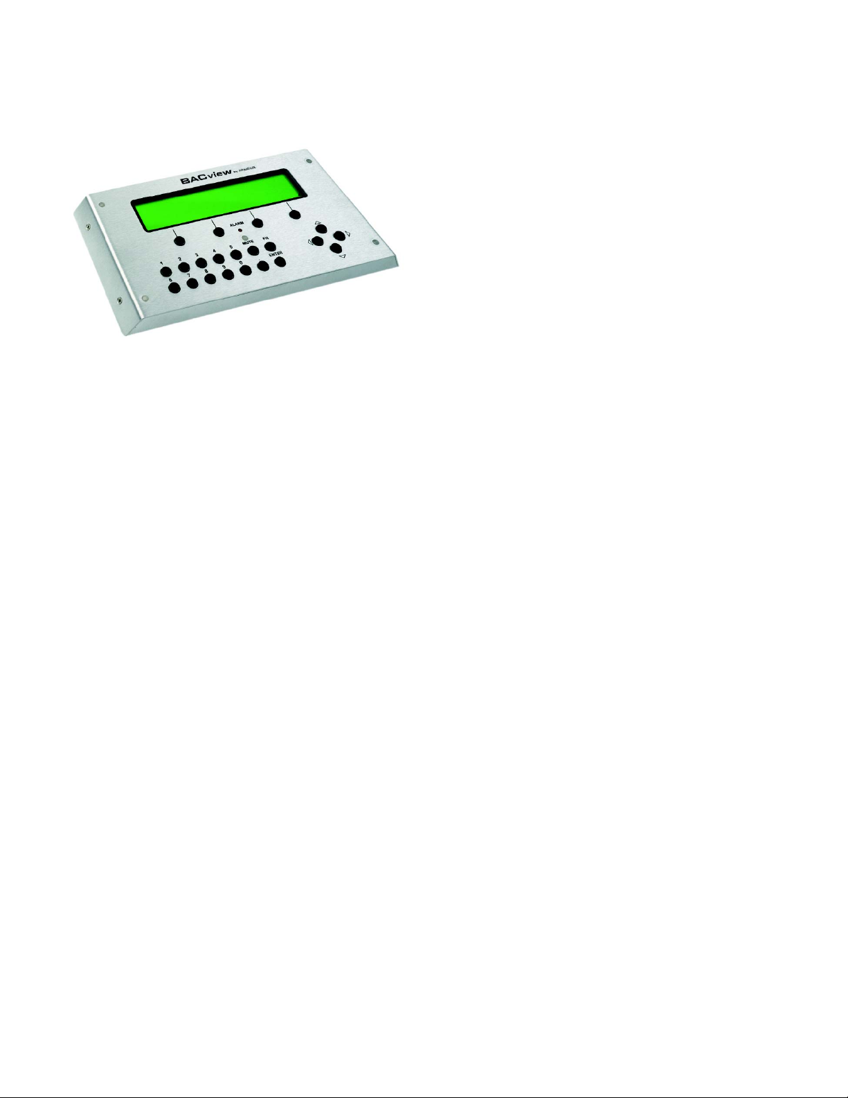
Keypad
Locally access controllers and operational properties
with the easy-to-use BACview
into an Rnet connection on a 6126 controller and allows you to display and modify properties. The BACview
6 features a numeric keypad, directional keys, and
four programmable function keys. A large 4-line by 40character backlit LCD display is provided for easy reading even in poor lighting conditions. The device also
includes an alarm indicator light.
Key Features and Benefits
Compatible with all EPiC system controllers.
Flexible design allows panel or wall mounting; can be located up to 500 feet from the controller.
Hand-held version can be plugged into RS room temperature sensors.
Backlit LCD display enhances reading even in poor lighting conditions.
Customized menus for each product.
Password protection provides security.
One keypad can be used on different units/programs since the menus are part of the control program.
6 keypad/display. It plugs
MAMM-WSHP-IOM-1MA (November 2011)
14
Page 15

General Maintenance
Normal maintenance on M-Vintage horizontal and vertical units is generally limited to filter changes.
Air filter changes are required at regular intervals. The
time period between changes will depend upon the project requirements. Some applications such as motels
produce a lot of lint from carpeting and linen changes,
and will require more frequent filter changes. It is suggested that the filter be checked at 60-day intervals for
the first year until experience is acquired. If light cannot
be seen through the filter when held up to sunlight or a
bright light, it should be changed. A more critical standard may be desirable.
The condensate drain pan should be checked annually
and cleaned and flushed as required.
Recording of performance measurements of volts,
amps, and water temperature differences (both heating
and cooling) is recommended. A comparison of logged
data with start-up and other annual data is useful as an
indicator of general equipment condition.
Periodic lockouts almost always are caused by air or
water problems. The lockout (shutdown) of the heat
pump is a normal protective result. Check for dirt in the
water system, water flow rates, water temperatures,
airflow rates (may be dirty filter), and air temperatures.
If the lockout occurs in the morning following a return
from night setback, entering air below machine limits
may be the cause.
MAMM-WSHP-IOM-1MA (November 2011)
15
Page 16
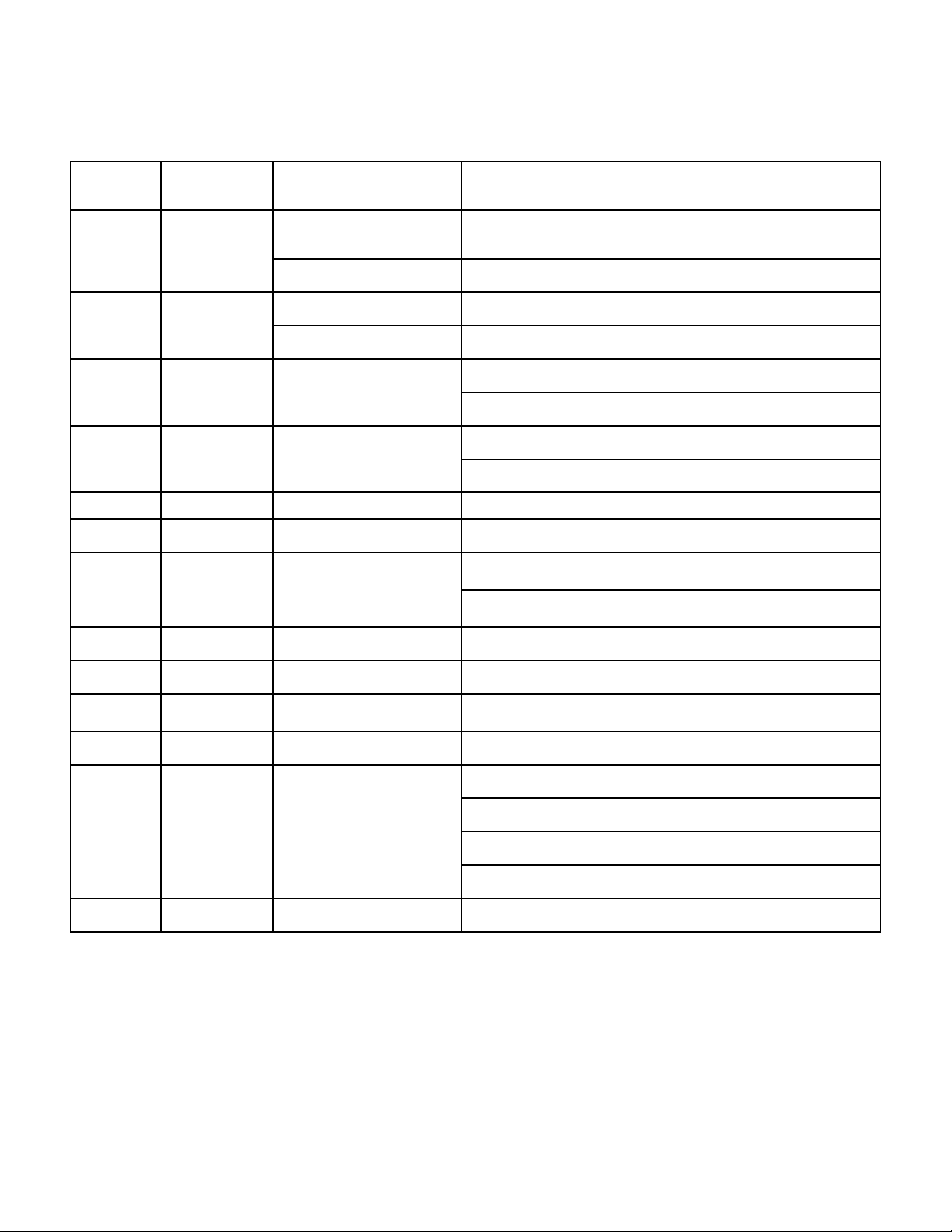
VFD GENERAL PURPOSE APPLICATION PARAMETERS
Parameter Default Value Description Comments
Reference Source 0 = Digital Operator (Adjust Motor Speed from keypad)
b1-01
b1-02 1
b1-03
b1-04 0 Reverse Operation
C1-01 10.0 sec. Acceleration Time The time it takes to ramp up from 0 to maximum motor speed.
C1-02 10.0 sec. Deceleration Time The time it takes to ramp down from maximum motor speed to 0.
1
Speed Control Method 1 = Terminals (Speed Pot. / 0 – 10V / 4—20mA)
Run Source / 0 = Digital Operator (Start/Stop motor from keypad)
Start/Stop Control Method 1 = Terminals (Start/Stop using external contact / switch)
0 = Ramp to stop (Motor ramps down at stop command)
1 Stop Method Selection
1 = Coast to stop (Motor freewheels at stop command)
0 = Allow motor to run in reverse direction
1 = Reverse direction prohibited
0 = Normal Duty (Use for fan and pump applications)
C6-01 1 Normal / Heavy Duty
0 = Normal Duty (Use for fan and pump applications)
d1-01 0.00 Hz Frequency Reference Frequency setting when speed is set from the keypad.
d2-01 100.0 % Frequency Upper Limit Maximum motor speed allowed (e.g. 100 % = Max rpm)
d2-02 0.0 % Frequency Lower Limit Minimum motor speed allowed (e.g. 100 % = Max rpm)
E2-01 * Motor Rated Current Motor nameplate current
0 = Disabled
1 = Standard Fan Cooled Motor
L1-01 1 Motor Overload Selection
2 = Standard Blower Cooled Motor
3 = Vector Duty Motor
L1-02 1.0 min Motor Overload Time Sets the motor thermal overload protection time.
MAMM-WSHP-IOM-1MA (November 2011)
16
Page 17
Troubleshooting
R-410A
The In’s and Out’s of R-410A
R-410A is a non-ozone depleting blend of two
Refrigerants — HFC-125 and HFC-32 in a fifty percent
mixture. Refrigerant 410A exhibits higher operating
pressure and refrigeration capacity than R-22.
Although R-410A is non-flammable at ambient temperature and atmosphere pressure, it can become
combustible under pressure when mixed with air.
(NOTE: R-410A should not be mixed with air under
pressure for leak testing. Pressure mixtures of dry nitrogen and R-410A can be used for leak testing.)
Lubrication
R410A should be used only with polyolester (POE) oil.
The HFC refrigerant components in R-410A will not be
compatible with mineral oil or alkylbenzene lubricants.
R-410A systems will be charged with the OEM recommended lubricant, ready for use with R-410A.
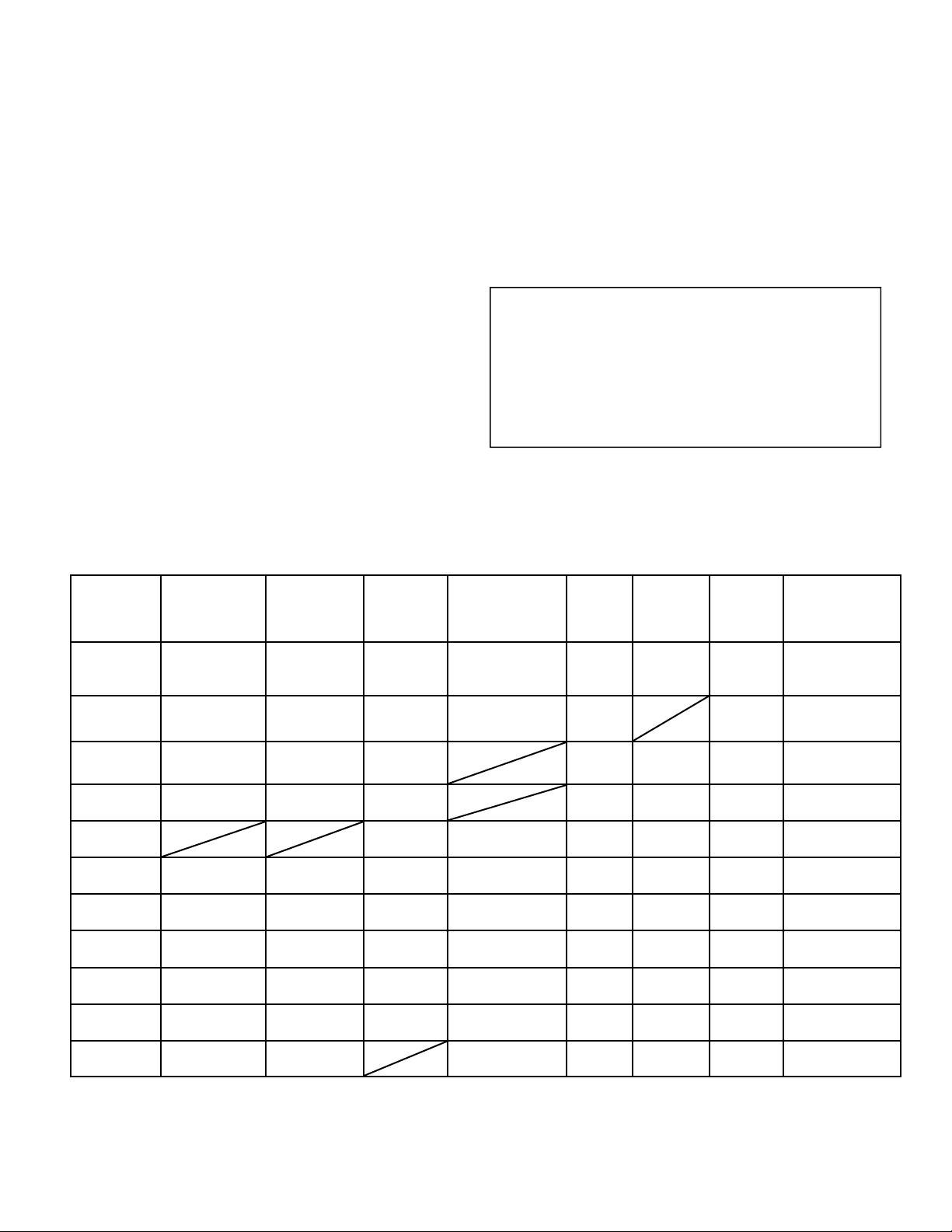
Troubleshooting Refrigeration Circuit
Symptom
Charge
Undercharge
System
(Possible Leak)
Overcharge System
Pressure
Low Air Flow
Heating
Low Air Flow
Cooling
Low Water Flow
Heating
Low Water Flow
Cooling
High Air Flow
Heating
High Air Flow
Cooling
High Water Flow
Heating
High Water Flow
Cooling
TXV Restricted High Low
Head
Pressure
Low Low Low High Low Low Low Low Pressure
High High High Normal Low
High High High
Low Low Low
Low Low
Normal Normal
High High High High Low Low High High Pressure
Low Low Low Low High Low Low Low Temp
Low High Normal High Low Low Normal High Pressure
Normal Low Low Low Normal Normal Low High Pressure
Low Low Low Low HIgh Normal Low Low Temp
Suction
Pressure
Compressor
Amp Draw
Low Low High Low High Low Temp
Normal
Low
Charging
Due to the zeotropic nature of R-410A, it should be
charged as a liquid. In situations where vapor is normally charged into a system, a valve should be installed in the charging line to flash the liquid to vapor
while charging.
WARNING!
It is very important to make certain that the recycle or
recovery equipment used is designed for R-410A. The
pressure of R-410A refrigerant is approximately 60
percent greater than that of R-22. Pressure gauges
require a range up to 800 PSIG high side and 250
PSIG low side. Recovery cylinders require a 400 PSIG
rating.
All Mammoth M-Vintage units are designed
for commercial use. Units are designed for the
cooling mode of operation and fail safe to heating.
Super
Heat
High
Normal
Low
Normal
High High Low Low
Subcooling
Low High Low High Pressure
Low Low Low Low Temp
Air
Temp
Differential
Normal
Low
Water
(Loops)
Temp
Differential
Normal High Pressure
Safety
Lock
Out
MAMM-WSHP-IOM-1MA (November 2011)
17
Page 18

Performance Troubleshooting
Performance
Troubleshooting
Insufficient Capacity X X Dirty Filter Replace or clean
Not cooling or heating
properly
X X Leaky duct work
Unit doesn’t operate in
cooling
X X
X Defective reversing valve Perform RV touch test
X X
X X Unit undersized
X X
X X Inlet water to hot or cold Check load, loop sizing, loop backfill, ground moisture
High head pressure X
X
Heating Cooling Possible Cause Solution
X X Reduced or no air flow
X X Low refrigerant charge Check superheat and subcooling
Restricted metering device
Thermostat improperly
located
Scaling in waterside heat
exchanger
Reduced or no air flow in
heating
Reduced or no water flow
in cooling
Check for dirty air filter and clean or replace, Check fan motor operation
and airflow restriction. External static too high? Check static vs. blower
table
Check supply and return air temperatures at the unit and at distant duct
registers: If significantly different, duct leaks are present
Check superheat and subcooling– replace
Check location and for air drafts behind stat
Recheck loads & sizing. Check sensible, cooling load and heat pump capacity
Perform scaling check and clean if necessary
Check for dirty air filter and clean or replace. Check fan motor operation
and airflow restrictions. External static too high? Check static vs. blower
table
Check pump operation or valve operation/setting. Check water flow; adjust
to proper flow rate
X Inlet water to hot Check load, loop sizing, loop backfill, ground moisture
X
X
X X Unit overcharged Check superheat and subcooling
X X
Low suction pressure X
X
X
X
X X Insufficient charge Check for refrigerant leaks
Low discharge air
temperature in heating
X Poor performance See insufficient capacity
X To high of air flow Check fan motor speed selection and airflow
Air temperature out of
range in heating
Scaling in waterside heat
exchanger
Non-condensable in
system
Reduced water flow in
heating
Water temperature out of
range
Reduced air flow in cooling
Air temperature out of
range
Bring return air temp within design parameters
Perform scaling check and clean if necessary
Vacuum system, reweigh in charge
Check pump operation or valve operation/setting. Check water flow adjust
to proper flow rate
Bring water temp within design parameters
Check for dirty air filter and clean or replace. Check fan motor operation
and airflow restrictions. External static too high? Check static vs. blower
table
Too much cold vent air? Bring entering air temp within design
parameters.
MAMM-WSHP-IOM-1MA (November 2011)
18
Page 19

UNIT CHECK-OUT SHEET
Customer Data
Customer Name ________________________________________ Date _________________________________________
Address ________________________________________________________________________________________________
Phone ________________________________________________ Unit Number___________________________________
Unit Nameplate Data
Make _______________________ Model Number ________________________ Serial Number _______________________
Compressor(s):
# 1: RLA_______ LRA _______ Refrig, Charge (oz.) _______ # 2: RLA_______ LRA _______ Refrig, Charge (oz.) ______
# 3: RLA_______ LRA _______ Refrig, Charge (oz.) _______ # 4: RLA_______ LRA _______ Refrig, Charge (oz.) ______
Blower Motor(s):
# 1: FLA (or NPA)________ HP __________ # 2: FLA (or NPA)________ HP __________
# 3: FLA (or NPA)________ HP __________ # 4: FLA (or NPA)________ HP __________
Maximum Fuse Size (Amps) __________ _____________ Minimum Circuit Ampacity (Amps) __________________
Operating Conditions
Unit Conditions Cooling Mode Heating Mode Measured At:
Entering Air Temperature _____________ _____________ _________________________________
Leaving Air Temperature _____________ _____________ _________________________________
Entering Fluid Temperature _____________ _____________ n/a
Leaving Fluid Temperature _____________ _____________ n/a
Fluid Flow (gpm) _____________ _____________ n/a
Fluid Side Pressure Drop _____________ _____________ n/a
Compressor # 1 # 2 # 3 # 4
Mode Cooling Heating Cooling Heating Cooling Heating Cooling Heating
Suction Pressure (psig) _______ _______ _______ _______ _______ _______ _______ _______
Discharge Pressure (psig) _______ _______ _______ _______ _______ _______ _______ _______
Suction Temp (at compressor) _______ _______ _______ _______ _______ _______ _______ _______
Discharge Temp (at compressor) _______ _______ _______ _______ _______ _______ _______ _______
Suction Superheat (at compressor) _______ _______ _______ _______ _______ _______ _______ _______
Liquid Line Leaving Condenser Temp _______ _______ _______ _______ _______ _______ _______ _______
Liquid Subcooling _______ _______ _______ _______ _______ _______ _______ _______
Volts/Amps
# 1 # 2 # 3 # 4
Phase
Compressor Volts _____ _____ _____ _____ _____ _____ _____ _____ _____ _____ _____ _____
Compressor Amps _____ _____ _____ _____ _____ _____ _____ _____ _____ _____ _____ _____
Blower Volts _____ _____ _____ _____ _____ _____ _____ _____ _____ _____ _____ _____
Blower Amps _____ _____ _____ _____ _____ _____ _____ _____ _____ _____ _____ _____
L1 L2 L3 L1 L2 L3 L1 L2 L3 L1 L2 L3
MAMM-WSHP-IOM-1MA (November 2011)
19
Page 20

[email protected]
www.mammoth-inc.com
Mammoth, Inc. has a policy of continuous product improvement and reserves the right to
change design and specifications without notice. FANWALL TECHNOLOGY
FANWALL® are trademarks of Huntair, Inc. This product is covered by one or more of the
following U.S. patents (7,137,775; 7,179,046; 7,527,468; 7,597,534) and other pending
U.S. or Canadian patent applications and/or foreign patents.
®
and
© 2011 Mammoth, Inc.
MAMM-WSHP-IOM-1MA
November 2011
 Loading...