

Page 1
T
ECHNICAL INFORMATION
Model No.
Description
RP2300FC, RP2301FC
Router
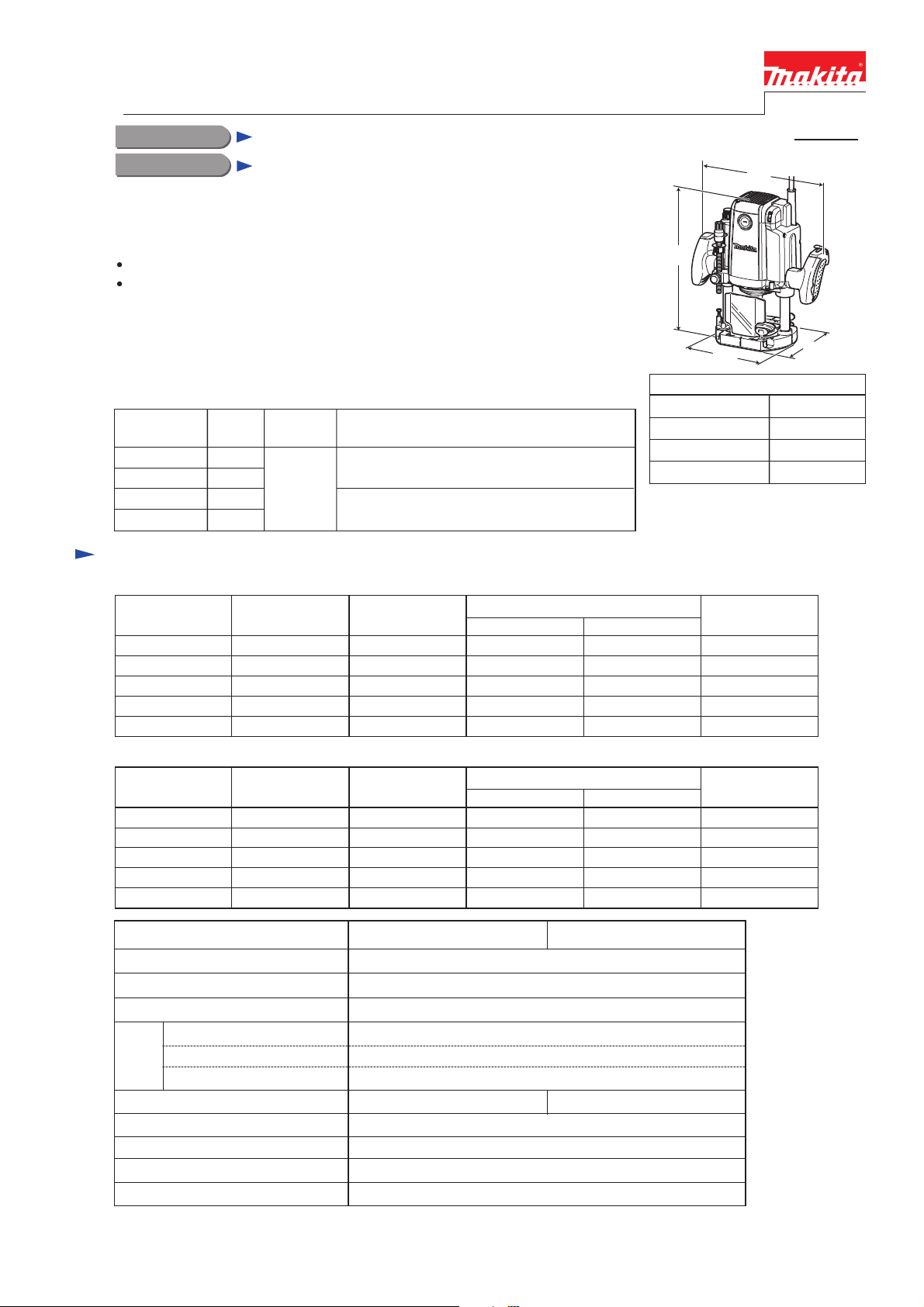
CONCEPT AND MAIN APPLICATIONS
Models RP2300FC and RP2301FC are upgraded sister tools of our current
plunge-type electronic router Model 3612C. Their main benefits are:
Linear ball bearing for super-smooth plunge action
Ergonomically contoured knob style handles
Powerful cutting with the continuous rating input higher than Model 3612C;
RP2300FC: 2,300W, RP2301FC: 2,100W
RP2301FC additionally feature electric brake.
PRODUCT
P 1/ 27
W1
H
L
W2
These products are available in the following variations.
No
Yes
No
Yes
Twin LED
job lights
Yes
(Straight guide + Guide holder assembly)
High-precision type with fine adjustment function
(Fine adjusting straight guide)
Model No.
RP2300FC
RP2301FC
RP2300FCX
RP2301FCX
Electric
brake
Specification
RP2300FC
Voltage (V) Cycle (Hz)
110
120
220
230
240
RP2301FC
Voltage (V) Cycle (Hz)
110
120
220
230
240
Current (A)
15 1,650
15 650 2,60050/60
11 2,300 1,200 3,40050/60
11 2,300 1,200 3,40050/60
11 2,300 1,200 3,40050/60
Current (A)
15 1,650
15 650 2,60050/60
10 2,100 1,000 3,40050/60
10 2,100 1,000 3,40050/60
10 2,100 1,000 3,40050/60
Straight guide
Standard type
Continuous Rating (W)
Input Output
Continuous Rating (W)
Input Output
---
---
Dimensions: mm (")
Length (L) 155 (6-1/8)
Width (W1)
Height (H)
Width of base (W2) 170 (6-11/16)
Max. Output (W)
650 2,60050/60
Max. Output (W)
650 2,60050/60
294 (11-5/8)
312 (12-1/4)
Model No.
No load speed: min-1=rpm
Collet capacity: mm (")
Plunge capacity: mm (")
Constant speed control
Soft start
control
Variable speed control by dial
Electronic
Electric brake
LED job light
Double insulation
Power supply cord: m (ft)
Net weight*2: kg (lbs)
*1: Twin LED job lights with afterglow function
*2 Weight according to EPTA-Procedure 01/2003, including Dust nozzle
(See next page for Standard equipment and Optional accessories.)
Europe: 4.0 (13.1), Brazil: 2.0 (6.6), Other countries: 2.5 (8.2)
No Yes
9,000 - 22,000
12.0 or 12.7 (1/2)
0 - 70 (0 - 2-3/4)
Yes
Yes
Yes
Yes*1
Yes
6.1 (13.4)
RP2301FCRP2300FC
Page 2

Standard equipment
For all countries:
Straight guide (Standard type or High-precision type) .................. 1 pc
+ Pan head screw M6x135 (for adjusting cutting depth) .............. 1 pc
The standard equipment for the tool shown below may vary by country:
Dust nozzle assembly ........... 1 pc
Knob 55 complete ................ 1 pc
Trimmer guide assembly ...... 1 pc
Templet guide 16 .................. 1 pc
Collet sleeve 6mm ............. 1 pc
Collet sleeve 8mm ............. 1 pc
Collet sleeve 1/4" ............... 1 pc
Collet sleeve 3/8" ............... 1 pc
Optional accessories
P 2/ 27
Collet cone 12mm or 1/2" ...... 1 pc
Wrench 24 .............................. 1 pc
Collet sleeve (for inch chuck) 10mm ..... 1 pc
Fine adjusting straight guide
Guide rail adapter set
Trimmer guide assembly
Templet guides
Templet guide 25
Templet guide adapter 30
Nut M30
Dust nozzle assembly
Collet sleeves
Router bits
Page 3
Repair
CAUTION: Remove the bit from the machine for safety before repair/ maintenance
in accordance with the instruction manual!
[1] NECESSARY REPAIRING TOOLS
[2] LUBRICATIONS
[3] DISASSEMBLY/ASSEMBLY
[3]-1. Base complete
Fig. 1
Fig. 2
Code No. Description Use for
1R030 Bearing setting pipe 25-17.2 Supporting Pin 6 when assembling shaft lock mechanism
1R268 Spring pin extractor 3 Removing Pin 6 of shaft lock mechanism
1R269 Bearing extractor Removing Ball bearing 629DDW
Item No.
Apply lubricant “VG100” to the following portions designated with the gray triangle to protect parts
and product from unusual abrasion.
Description
Armature
Portion to lubricate
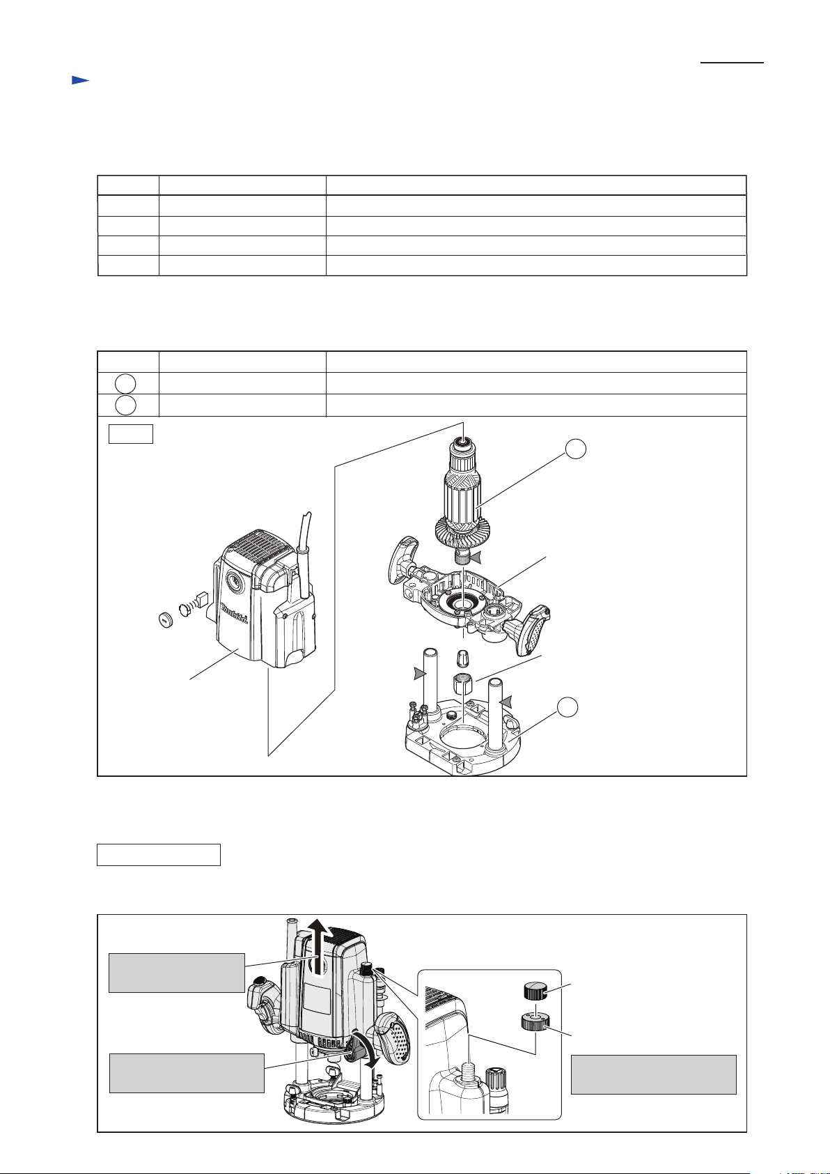
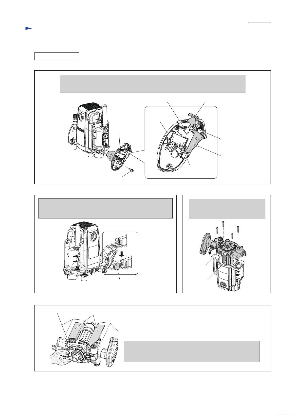
DISASSEMBLING
(1) Separate Base section from Motor section as illustrated in Figs. 2 and 3.
3. Remove M10 Thumb nut
and M10 Nylon nut
24
Motor bracket complete
Collet nut
Motor housing
85
24
85 Base complete
Threaded portion for removing Collet nut smoothly
Pipe 20 for making plunging action smooth
M10 Thumb nut
M10 Nylon nut
1R041 Vise plate Protecting Armature when holding in vise
1. Set Motor section to
the upper position.
2. Lock Motor section
by turning Lock lever.
P 3/ 27
Page 4
[3] DISASSEMBLY/ASSEMBLY
[3]-1. Base complete (cont.)
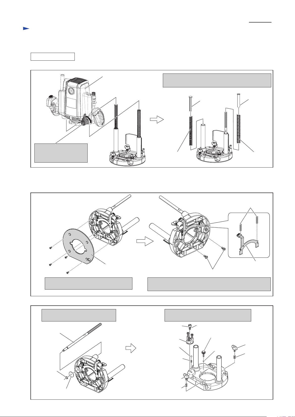
DISASSEMBLING
4. Loosen Lock lever.
Base can be separated
from Motor section.
5. Remove Pole, Silent pole, Compression spring 13
and Compression spring 11.
6. Remove Base plate by unscrewing
M4x10 Countersunk head screw (4pcs.)
7. Remove Lock plate by unscrewing M5x10 Set bolt (2pcs.)
Separate Compression spring 4 (2pcs.) from Lock plate.
M4x10
Countersunk
head screw
(4pcs.)
Base plate
The other parts can be removed from Base
complete as illustrated below.
Lock plate
Compression
spring 4 (2pcs.)
M5x10 Set bolt (2pcs.)
Motor section
M6 Hex nut
M10 Screw
Remove M6 Hex nut, Flat washer 6
and M10 Screw.
Stopper
Compression spring 5
Compression spring 7
Compression
spring 7
Steel ball 7.1
M4x19 Thumb screw
M5x14 Thumb screw
M5x14
Thumb screw
O ring 3
M6 Flat head screw O ring 8
Flat washer 6
Fig. 3
Fig. 4
Fig. 5
(2) Remove Base plate, Lock plate, Compression spring 4 and other component parts.
Refer to Figs. 4 and 5.
Silent pole
Pole
Compression
spring 11
Compression
spring 13
Repair
P 4/ 27
Page 5
[3] DISASSEMBLY/ASSEMBLY
[3]-1. Base complete
DISASSEMBLING
ASSEMBLING
Fig. 6
Fig. 7
Fig. 8
Lock plate
Lever portion of Lock plate
Hook of Lock plate
1. Screw M5x10 Set bolt (2pcs.) to Base complete 2. Set Compression spring 4 in place between the groove end of
Base complete and the hook of Lock plate.
Groove end of Base complete
M5x10 Set bolt (2pcs.)
Compression
spring 4
Take the disassembling step in reverse.
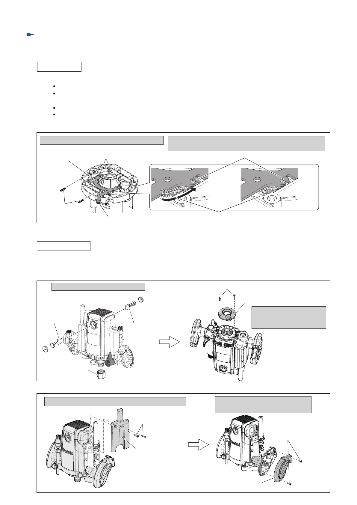
[3]-2. Armature, Motor bracket complete
(1) Separate Base section from Motor section as illustrated in Figs. 2 and 3.
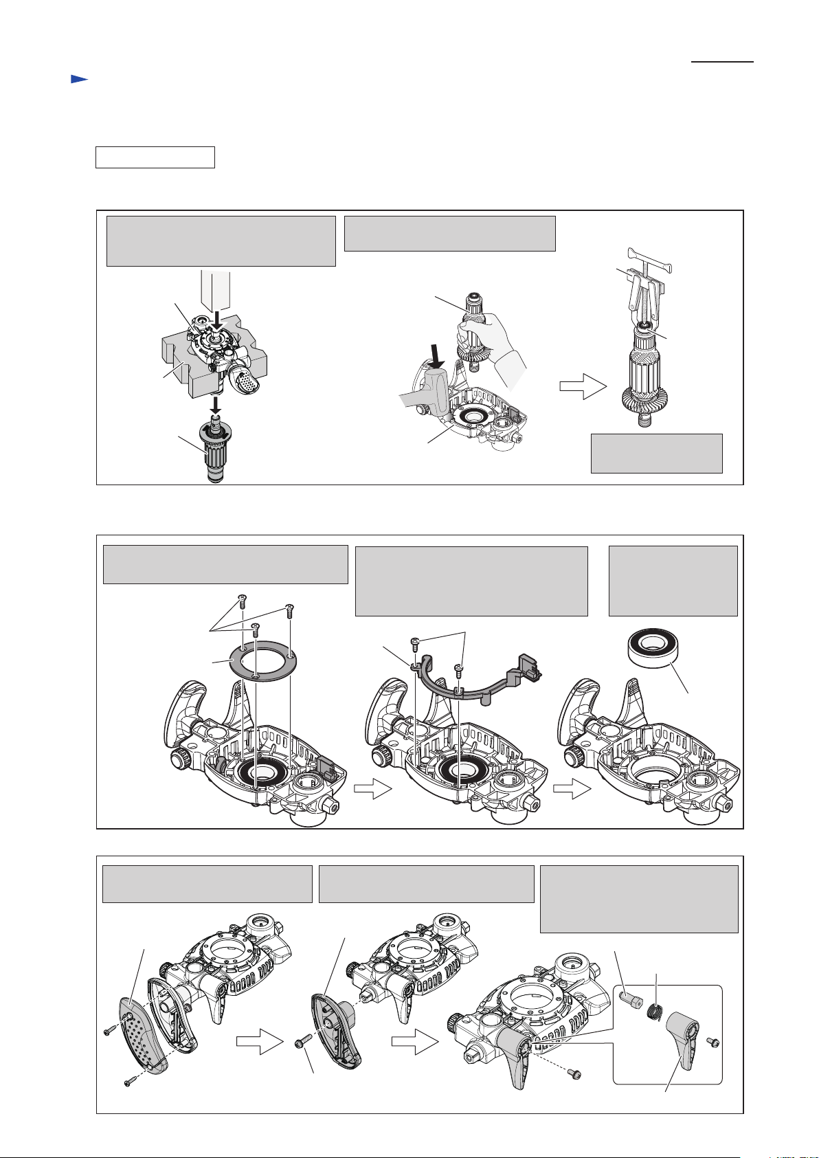
(2) Disassemble Armature as illustrated in Figs. 7, 8, 9, 10, 11, 12 and 13.
Collet nut
Carbon brush
Carbon brush
Cover
Remove carbon brush and Collet nut.
Remove Retainer cover by
unscrewing M4x18 Pan head
screw (2pcs.)
Remove Cover by unscrewing 4x18 Tapping screw (2pcs.)
Note: It is impossible to
disassemble Grip R
without removing
Cover.
M4x18 Pan head screw (2pcs.)
4x18 Tapping screw
(2pcs.)
4x18 Tapping
screw (2pcs.)
Retainer cover
Grip cover (R)
Remove Grip cover (R) by unscrewing
4x18 Tapping screw (2pcs.)
Repair
Note: Set Compression spring 4 (2pcs.) in the groove on Base complete as illustrated in Fig. 6
M6 - Flat head screw is thread-locker type. When removing it, be sure to apply adhesive (ThreeBond 1321/ 1342
or Loctite 242) to the thread before reusing.
Assemble Compression spring 11, Compression spring 13, Pole and Silent pole as illustrated in Fig. 3.
Check that two Compression springs 4 work properly by pulling the lever portion of Lock plate after assembling
Base plate to Base. Refer to Figs. 6 and 4.
P 5/ 27
Page 6
[3] DISASSEMBLY/ASSEMBLY
[3]-2. Armature, Motor bracket complete (cont.)
DISASSEMBLING
Compression
spring 4
Switch
lever
Compression spring 5
Lock off button
Grip R
Switch
Grip R
Connector of Controller
In case of Models RP1800F, RP1801F, RP2300FC and RP2301FC,
disconnect Connector of Controller from LED circuit prior to
the step described in Fig. 11.
Disassemble Switch lever, Lock off button, Compression spring 5, Compression spring 4
from Grip R. And remove Grip R from the machine by unscrewing M5x25 Pan head screw.
In case of Models RP1800 and RP1801, refer to Fig. 11.
M5x25 Pan Head screw
Fig. 9
Fig. 10 Fig. 11
Fig. 12
Armature
Motor
bracket
Remove Motor bracket together with
Armature from Motor housing by
removing 5x35 Tapping screw (4pcs.)
5x35 Tapping
screw (4pcs.)
1R041
Retainer
Remove Retainer from Armature shaft by:
1) holding Armature using 1R041 and vise
2) turning counterclockwise with Wrench 41 or Hex socket 41-80.
Repair
P 6/ 27
Page 7
[3] DISASSEMBLY/ASSEMBLY
[3]-2. Armature, Motor bracket complete (cont.)
DISASSEMBLING
Fig. 13
Fig. 14
Fig. 15
(3) Armature can be removed in the manner A or B shown in Fig. 13. Remove Ball bearing 629DDW from Armature.
(4) Disassemble the Motor bracket as illustrated in Figs. 14 and 15.
Motor bracket
Remove Ball bearing
629DDW with 1R269.
Remove Bearing retainer 60 by unscrewing
M4x14 Countersunk head screw.
In case of Models RP1800F, RP1801F,
RP2300FC and RP2301F, remove LED
Circuit by removing Bind CT4x12
Tapping screw (2pcs.)
A: Supporting Motor bracket with 2 pcs.
of 1R258, remove Armature with
Arbor press.
1R258
Armature
Bearing retainer 60
Ball bearing
6205DDW
Remove Ball bearing
6205DDW by striking
Motor bracket with
Plastic hammer.
Bind CT4x12
Tapping screw (2pcs.)
4x12 Tapping
screw (2pcs.)
M4x14 Countersunk
head screw (3pcs.)
LED circuit
Grip cover L
Remove Grip cover L by unscrewing
4x12 Tapping screw (2pcs.)
Grip L can be removed by unscrewing
M6x25 Pan head screw.
Grip L
M5x12 Pan
head screw Lock lever
Remove Lock lever by unscrewing
M5x12 Pan head screw.
Separate M10 Set bolt and Torsion
spring 15 from Lock lever.
Torsion spring 15
M10 Set bolt
M6x25 Pan head screw
Motor bracket
Ball bearing
629DDW
Armature
1R269
Repair
B: Strike Motor bracket with Plastic
hammer while gripping Armature.
P 7/ 27
Page 8
[3] DISASSEMBLY/ASSEMBLY
[3]-2. Armature, Motor bracket complete
ASSEMBLING
(1) Assemble Ball bearing 6205DDW to Motor bracket. Refer to the right illustration in Fig. 14.
(2) In case of RP1800F, RP1801F, RP2300FC and RP2301FC, secure LED circuit with 4x12 Tapping screw (2pcs.).
Refer to the center illustration in Fig. 14.
(3) Tighten Bearing retainer 60 with M4x14 Countersunk head screw (3pcs.) to secure Ball bearing 6205DDW.
Refer to the left illustration in Fig. 14.
Note: Apply adhesive ThreeBond 1321 / 1342 or Loctite 242 to the threaded portion of M4x14 Countersunk head
screw (3pcs.)
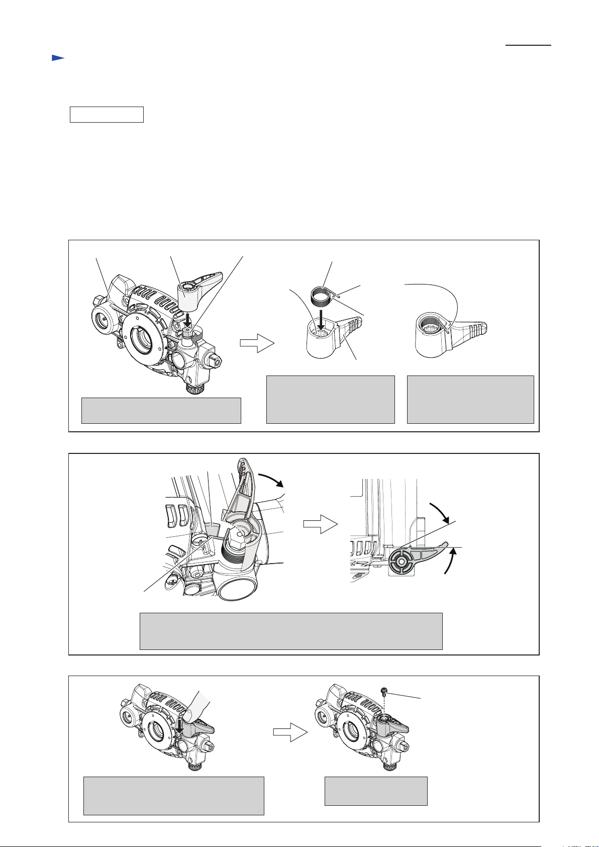
(4) Assemble Lock lever to Motor bracket as illustrated in Figs. 16, 17 and 18.
Hooking the long tail of Torsion spring 15 on the wall of Motor bracket,
turn Lock lever without engaging the spline hole with the hex screw head
of M10 Set bolt until it comes to the position illustrated right.
M10 Set boltLock lever
Screw M10 Set bolt to Motor bracket
with Lock Lever.
Put Torsion spring 15 into
Lock lever so that the short tail
of Torsion spring 15 faces
Lock lever.
Putting the long tail of
Torsion spring 15 on
the edge of Lock lever,
set Torsion spring 15 in place.
Motor bracket
Short tail
Long tail
Spline hole
Long tail of
Torsion spring 15
Wall
Torsion spring 15
Lock lever
30 degrees
Engaging the spline hole of the Lock lever
with the hex screw head of M10 Set bolt,
push Lock lever as illustrated above.
Secure Lock lever with
M5x12 Pan head screw.
M5x12 Pan head
screw
Fig. 16
Fig. 17
Fig. 18
Repair
P 8/ 27
Page 9
[3] DISASSEMBLY/ASSEMBLY
[3]-2. Armature, Motor bracket complete (cont.)
DISASSEMBLING
ASSEMBLING
(5) Assemble Grip L to Motor bracket on Lock lever side and secure it with M6x25 Pan head screw. Refer to Fig. 15.
Assemble Grip cover L to Grip L by screwing two 4x12 Tapping screws. Refer to Fig. 15.
(6) Assemble Armature to Motor bracket. Refer to Fig. 13
(7) Assemble Retainer to Armature shaft by turning with Wrench 41 or Hex socket 41-80 clockwise. Refer to Fig. 12.
(8) Assemble Motor bracket to Motor housing. Refer to Fig. 11.
(8) In case of Models RP1800F, RP1801F, RP2300F, RP2301FC, connect LED circuit. Refer to Fig. 10.
(9) Assemble Grip R section to Motor bracket. Refer to Fig. 9.
(10) Secure Grip cover (R) with two 4x18 Tapping screws to the Grip R. Refer to right illustration in Fig. 8.
And assemble Cover to Motor housing. Refer to left illustration in Fig. 8.
(11) Mount Retainer cover to Motor bracket. Refer to right illustration in Fig. 7. And assemble Carbon brushes and
Collet nut. Refer to left illustration in Fig. 7.
[3]-3. Shaft Lock
(1) Separate Base section from Motor section as illustrated in Figs. 2, 3.
(2) Remove Retainer cover by unscrewing two M4x18 Pan head screws as the right illustration in Fig. 7.
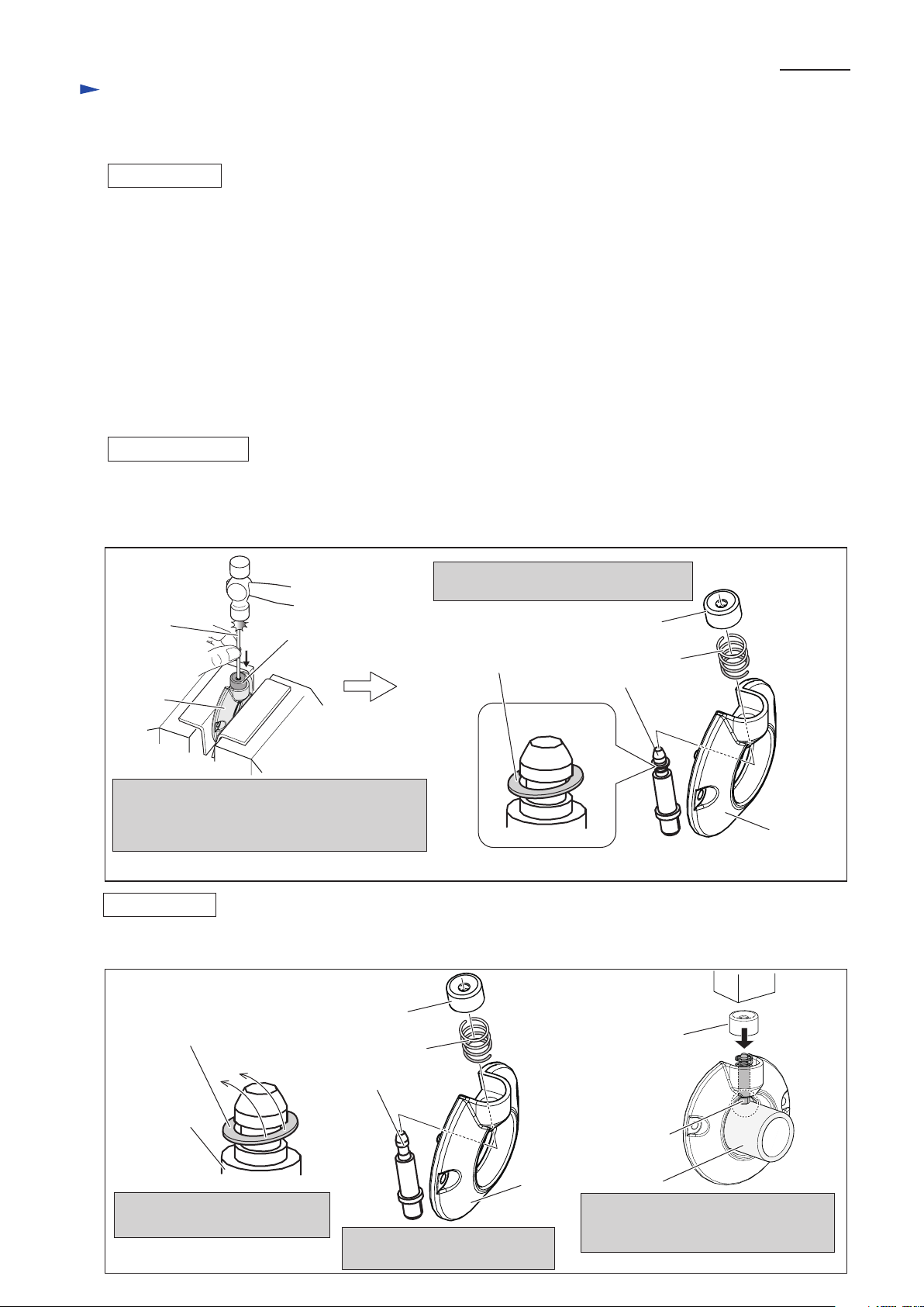
(3) Shaft lock mechanism can be disassembled as illustrated in Fig. 19.
Fig. 19
1R268
Retainer
cover
Applying 1R268 to the pin hole of Push button,
strike Collared pin 6 through the pin hole of
Push button.
Collared pin 6 can be removed from Push button.
Collared pin 6 and Compression spring 8
are removed from Push button.
Push button
Push button
Collared pin 6
Splinter of
Push button
Push button
Compression spring 8
Retainer
cover
Note: The removed Push button has to be replaced with new Push button.
Repair
ASSEMBLING
Shaft lock section can be assembled as illustrated in Fig. 20.
Splinter of
Push button
Fig. 20
Push Button
Note: Use new Push button.
Collared pin 6
Collared pin 6
1R030
Collared pin 6
Compression spring 8
Retainer
cover
Remove Splinter of Push button
from Collared pin 6.
Set the parts to Retainer cover
as illustrated above.
Supporting Collared pin 6 with 1R030,
assemble Push button by pressing with
Arbor press.
P 9/ 27
Page 10

Circuit diagram
RP2301FC with electric Brake, LED Job Light, Electronic Control
White
Orange
Purple
Color index of lead wires' sheath
* Support unit without Choke coil is used for some countries.
Black
Makita
logo side
Name
plate side
Motor housing
Grip R
Controller
Power
supply
cord
LED
Circuit
*Support Unit
Chokecoil
Switch
Connector
of Controller
Connector
of LED
Yellow
Red
Fig. D-1A
This Lead wire
may be blue for
some countries.
Brown Lead wire
is used for some
countries.
Blue Lead wire
is used for
some countries.
P 10/ 27
Page 11

Wiring diagram
RP2301FC with electric Brake, LED Job Light, Electronic Control
Grip R
Lead Wire
Holder
When putting Lead wires for
connecting to Terminal block,
into this Lead wire holder,
Controller’s thin Lead wire (purple)
has to be put under the following
Lead wires.
* Controller’s thick Lead wire (red)
* Thick Connecting lead wire (purple)
for connecting Switch to Terminal
block
Switch lever
Connector
of Controller
The extra portion of Controller’s
thin Lead wires (black, red) to be
connected to LED has to be put
in this position.
Connector of Controller’s lead wires
has to be connected to LED circuit
that facies Lead wire (Red) to Red
marking side.
And put the Lead wires into Lead
wire holder.
Terminal block
Red marking
Controller’s Lead wire (red)
Lead wire holder
Wiring in Motor housing
on Grip R side (Switch side)
Connecting Lead Wires
(yellow, orange purple) to
be connected to Switch in
Grip R
Fig. D-2A
P 11/ 27
Page 12

Wiring diagram
RP2301FC with electric Brake, LED Job Light, Electronic Control
Fig. D-3A
Lead wire holder
Wiring in Motor housing
on top side (Rear cover side)
Wiring in Grip (R)
Support unit
When putting Support unit’s Lead wires
into Lead wire holders, put them as follows.
* Support unit’s Lead wire (black)
into Lead wire holder of outside
* Support unit’s Lead wires (orange, yellow)
into Lead wire holder of inside
Controller
Support unit’s Lead wire (orange)
Support unit’s Lead wire (black)
Insulated connector
Connect Insulated connector to
Switch terminal 2 while keeping
it away from Boss.
Support unit’s Lead wire (yellow)
Put Controller into
the above illustrated
position.
Switch terminal 2
RP2301FC with electric Brake, LED Job Light, Electronic Control
Boss
P 12/ 27
Page 13

Circuit diagram
RP2300FC with LED Job Light, Electronic Control
White
Orange
Purple
Color index of lead wires' sheath
Black
Makita
logo side
Name
plate side
Motor housing
Grip R
Controller
Power
supply
cord
LED
Circuit
Support unit
Blue Lead wire
is used for
some countries.
Brown Lead wire
is used for some
countries.
Switch
Connector
of Conroller
Connector
of LED
Red
Fig. D-1B
Blue Lead wire
is used for
some countries.
P 13/ 27
Page 14

Wiring diagram
RP2300FC with LED Job Light, Electronic Control
Grip R
Lead Wire
Holder
When putting Lead wires for
connecting to Terminal block,
into this Lead wire holder,
Controller’s thin Lead wire (purple)
has to be put under the following
Lead wires.
* Controller’s thick Lead wire (red)
* Thick Connecting lead wire (purple)
for connecting Switch to Terminal
block
Switch lever
Connector
of Controller
The extra portion of Controller’s
thin Lead wires (black, red) to be
connected to LED has to be put
in this position.
Connector of Controller’s lead wires
has to be connected to LED circuit,
facing Lead wire (Red) to Red
marking side.
And put the Lead wires into Lead
wire holder.
Terminal block
Wiring in Motor housing
on Grip R side (Switch side)
Connecting lead wires
(orange purple) to be
connected to Switch in
Grip R
Fig. D-2B
Lead wire holder
Controller’s lead wire (red)
Red marking
P 14/ 27
Page 15

Wiring diagram
RP2300FC with LED Job Light, Electronic Control
Fig. D-3B
Lead wire holder
Wiring in Motor housing
on top side (Rear cover side)
Wiring in Grip R
Support unit
When putting Support unit’s Lead wires
into Lead wire holders, put them as follows.
* Support unit’s Lead wire (black)
into Lead wire holder of outside
* Support unit’s Lead wire (orange)
into Lead wire holder of inside
Controller
Support unit’s Lead wire (orange) Support unit’s Lead wire (black)
Put Controller into
the above illustrated
position.
RP2300FC with LED Job Light, Electronic Control
Insulated connector
Connect Insulated connector to
Switch terminal 2 while keeping
it away from Boss.
Switch terminal 2
Boss
P 15/ 27
Page 16

Circuit diagram
RP1801F with electric Brake, LED Job Light
White
Orange
Purple
Color index of lead wires' sheath
* Support unit without Choke coil is used for some countries.
Black
Makita
logo side
Name
plate side
Motor housing
Grip R
Power supply circuit
Power
supply
cord
LED
Circuit
*Support unit
Choke coil
Switch
Connector
of Conroller
Connector
of LED
Yellow
Red
Fig. D-1C
Brown Lead wire
is used for
some countries.
Blue Lead wire
is used for
some countries.
Blue Lead wire
is used for
some countries.
P 16/ 27
Page 17

Wiring diagram
P 17/ 27
R1801F with electric Brake, LED Job Light
Grip R
Lead wire
holder
When putting Lead wires for connecting
to Terminal block, into this Lead wire holder,
thin Lead wire (purple) of Power supply circuit
has to be put under the following Lead wires.
* Thick Lead wire (red) of Power supply circuit
* Thick Connecting lead wire (purple) for
connecting Switch to Terminal block
Switch lever
The extra portion of Controller’s
thin Lead wires (black, red) to be
connected to LED has to be put
in this position.
Connector of Controller’s lead wires
has to be connected to LED circuit,
facing Lead wire (Red) to Red
marking side.
And put the Lead wires into Lead
wire holder.
Terminal block
Lead wire holder
Connector of
controller
Red marking
Controller’s Lead wire (red)
Wiring in Motor housing
on Grip R side (Switch side)
Connecting lead wires
(yellow, orange purple) to
be connected to Switch in
Grip R
Fig. D-2C
Page 18

Wiring diagram
RP1801F with electric Brake, LED Job Light
RP1801F with electric Brake, LED Job Light
Fig. D-3C
Lead wire holder
Wiring in Motor housing
on top side (Rear cover side)
Support unit
When putting Support unit’s Lead wires
into Lead wire holders, put them as follows.
* Support unit’s Lead wire (black)
into Lead wire holder of outside
* Support unit’s Lead wires (orange, yellow)
into Lead wire holder of inside
Power supply circuit
Support unit’s Lead wire (orange)
Support unit’s Lead wire (black)
Insulated connector
Wiring in Grip R
Connect Insulated connector to
Switch terminal 2 while keeping it
away from Boss.
Support unit’s Lead wire (yellow)
Put Power supply
circuit into the above
illustrated position.
Switch terminal 2
Boss
P 18/ 27
Page 19

Circuit diagram
RP1801 with electric Brake
White
Orange
Purple
Color index of lead wires' sheath
Black
Makita
logo side
Name
plate side
Motor housing
Grip R
Power
supply
cord
*Support unit
Choke coil
Switch
Yellow
Fig. D-1D
Blue Lead wire
be used for
some countries.
Brown Lead wire
be for some
countries.
Noise
Suppressor
* Noise suppressor is not used for some countries.
P 19/ 27
Page 20

Wiring diagram
RP1801 with electric Brake
Grip R
Lead Wire
Holder
When putting Lead wires for
connecting to Terminal block,
into this Lead wire holder,
Noise suppressor’s thin Lead wire
(white) has to be put under the
following Lead wires.
* Support unit’s lead wire (black)
* Thick Connecting lead wire (purple)
for connecting Switch to Terminal
block
Switch lever
Terminal block
Connecting lad wires
(yellow, orange purple) to
be connected to Switch in
Grip R
Fig. D-2D
Noise
suppressor
Wiring in Motor housing
on Grip R side (Switch side)
P 20/ 27
Page 21

Wiring diagram
RP1801 with electric Brake
RP1801 with electric Brake
Fig. D-3D
Lead wire holder
Support unit
Wiring in Motor housing
on top side (Rear cover side)
Wiring in Grip (R)
When putting Support unit’s Lead wires
into Lead wire holders, put them as follows.
* Support unit’s Lead wire (black)
into Lead wire holder of outside
* Support unit’s Lead wires (orange, yellow)
into Lead wire holder of inside
Support unit’s Lead wire (orange)
Support unit’s Lead wire (black)
Insulated connector
Connect Insulated connector to
Switch terminal 2 while keeping it
away from Boss.
Support unit’s Lead wire (yellow)
Switch terminal 2
Boss
P 21/ 27
Page 22

Circuit diagram
RP1800F with LED Job Light
White
Orange
Purple
Color index of lead wires' sheath
Black
Makita
logo side
Name
plate side
Motor housing
Grip R
Power supply circuit
Power
supply
cord
LED
circuit
Support unit
Blue Lead wire
is used for
some countries.
Blue Lead wire
is used for
some countries.
Brown Lead wire
is used for some
countries.
Switch
Connector
of Conroller
Connector
of LED
Red
Fig. D-1E
P 22/ 27
Page 23

Wiring diagram
RP1800F with LED Job Light
Grip R
Lead Wire
Holder
Switch lever
Connector
of Controller
The extra portion of Controller’s
thin Lead wires (black, red) to be
connected to LED has to be put
in this position.
Connector of Controller’s lead wires
has to be connected to LED circuit,
facing Lead wire (Red) to Red
marking side.
And put the Lead wires into Lead
wire holder.
Lead wire holder
Terminal block
Red marking
Controller’s Lead wire (red)
Wiring in Motor housing
on Grip R side (Switch side)
Connecting lead wires
(orange purple) to be
connected to Switch in
Grip R
Fig. D-2E
When putting Lead wires for connecting
to Terminal block, into this Lead wire holder,
thin Lead wire (purple) of Power supply circuit
has to be put under the following Lead wires.
* Thick Lead wire (red) of Power supply circuit
* Thick Connecting lead wire (purple) for
connecting Switch to Terminal block
P 23/ 27
Page 24

Wiring diagram
Wiring in Motor housing
on top side (Rear cover side)
RP1800F with LED Job Light
Fig. D-3E
Lead wire holder
Support Unit
When putting Support unit’s Lead wires
into Lead wire holders, put them as follows.
* Support unit’s Lead wire (black)
into Lead wire holder of outside
* Support unit’s Lead wire (orange)
into Lead wire holder of inside
Power supply
circuit
Support unit’s Lead wire (orange) Support unit’s Lead wire (black)
Put Power supply
circuit into the above
illustrated position.
Wiring in Grip (R)
RP1800F with LED Job Light
Insulated connector
Connect Insulated connector to
Switch terminal 2, keeping it
away from the Boss.
Switch terminal 2
Boss
P 24/ 27
Page 25

Circuit diagram
RP1800
White
Orange
Purple
Color index of lead wires' sheath
* Noise suppressor is not used for some countries.
Black
Makita
logo side
Name
plate side
Motor housing
Grip R
Power
supply
cord
Support unit
Switch
Fig. D-1F
Blue Lead wire
is used for
some countries.
Brown Lead wire
is used for some
countries.
Noise
suppressor
P 25/ 27
Page 26

Wiring diagram
RP1800
Grip R
Lead Wire
Holder
When putting Lead wires for
connecting to Terminal block,
into this Lead wire holder,
Noise suppressor’s thin Lead wire
(white) has to be put under the
following Lead wires.
* Support unit’s lead wire (black)
* Thick Connecting lead wire (purple)
for connecting Switch to Terminal
block
Switch lever
Terminal block
Wiring in Motor housing
on Grip R side (Switch side)
Connecting lead wires (orange, purple)
to be connected to Switch in Grip R
Fig. D-2F
Noise
suppressor
P 26/ 27
Page 27

Wiring diagram
Wiring in Motor housing
on top side (Rear cover side)
RP1800
Fig. D-3F
Lead wire holder
Support unit
When putting Support unit’s Lead wires
into Lead wire holders, put them as follows.
* Support unit’s Lead wire (black)
into Lead wire holder of outside
* Support unit’s Lead wire (orange)
into Lead wire holder of inside
Support unit’s lead wire (orange) Support unit’s lead wire (black)
Wiring in Grip (R)
RP1800
Insulated connector
Connect Insulated connector to
Switch terminal 2 while keeping
it away from Boss.
Switch terminal 2
Boss
P 27/ 27
 Loading...