

Makita PLANER JOINTER 2004, 2004 Instruction Manual
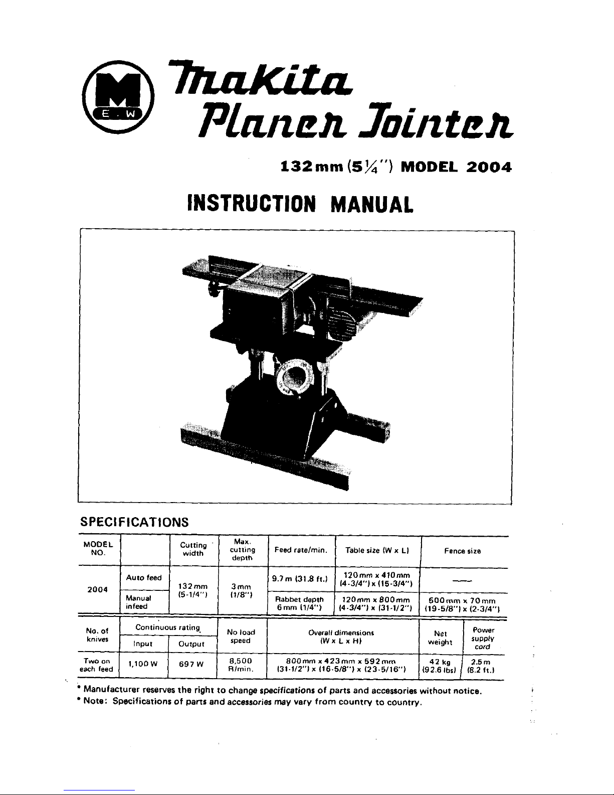
132
mm
(5%")
MODEL
2004
NO.
MODEL
2004
No,
of
knives
Two
on
each feed
INSTRUCTION
MANUAL
width
-
czkg Feed ratelmin. Table size fW
x
L)
Fence size
depth
-
120"
x
410"
Auto feed
9.7m
131'8ft') (4.3/4")~(15.3/4")
132" 3mm
~
Manual f5-1/4")
f118")
Rabbet depth l2Omm
x
8OOmm
500" x 70"
infeed
6mm
1114"l
1444")
x
131-1/2"1
119-5/8") x (2-3/4")
No
load Overall dimensions Power
Continuour rating,
Input
Output
speed fWx
Lx
HI
ws"$),
SUPPk
cord
8.500 800mm
x
423" x 592"
42
kg
2.5m
'''0°
697
R/min. 131.1/2") X (16-5/8") x 123.5/16') (92.6
lbsl
18.2
ft.)
BEFORE CONNECTING YOUR TOOL
TO
A
POWER SOURCE
Be
sure
you
have
read
all
GENERAL POWER TOOL SAFETY RULES
GENERAL SAFETY PRECAUTIONS
1.
KEEP GUARDS IN PLACE and
in
working order.
2.
REMOVE ADJUSTING KEYS AND WRENCHES.
Form habit of checking to
see
that keys and adjusting wrenches are removed from tool before turning
it
on.
3.
KEEP WORK AREA CLEAN. Cluttered areas
and
benches invite accidents.
4.
AVOID DANGEROUS ENVIRONMENT. Don't
use
power tools in damp or wet
locations. Keep work
area
well
lit.
5.
KEEP CHILDREN AWAY. All visitors should
be
kept
safe
distance from work area.
6.
MAKE WORKSHOP KID PROOF
-With
padlocks, master switch-, or by remov-
7.
DON'T FORCE TOOL.
It
will do
the
job
better and safer
at
the rate for which
it
8.
USE
RIGHT
TOOL. Don't force tool or attachment to do a job
it
was not designed
9.
WEAR PROPER APPAREL. No loose clothing or jewelry to get caught
in
moving
10.
USE SAFETY GLASSES. Also
use
face or dust mask
if
cutting operation
is
dusty.
11.
SECURE WORK. Use clamps or a vise to hold work when practical.
It's
safer than
12.
DON'T OVERREACH. Keep proper footing and balance
at
all
times.
13.
MAINTAIN TOOLS WITH CARE. Keep tools sharp and clean for best and
safest
performance. Follow instructions for lubricating and changing accessories.
14.
DISCONNECT TOOLS before servicing; when changing accessories such
as
cutter
blades.
15.
AVOID ACCIDENTAL STARTING. Make sure switch
is
in
off
position before
plugging in.
16.
USE RECOMMENDED ACCESSORIES. Consult the owner's manual for recommended accessories. The use
of
improper accessories may cause hazards.
17.
NEVER STAND ON TOOL. Serious injury could occur
if
the
tool
is
tipped or
if
the cutting tool
is
accidentally contacted.
18.
CHECK DAMAGED PARTS.
Before further use of
the
tool, a guard or other part
that
is
damaged should be carefully checked to ensure that
is
will operate properly
and perform
its
intended function - check for alignment
of
moving
parts,
binding
of moving parts, breakage of
parts,
mounting, and any other conditions that
may
affect
its
operation. A guard or other part that
is
damaged should
be
properly
re-
paired or replaced.
19.
PROPER GROUNDING. These tools should be grounded while in
use
to protect
the
operator from electric shock.
ing starter keys.
was designed.
for.
parts. Rubberjoled footwear
is
recommended for best footing.
using your hand and
it
frees both hands to operate
tool.
PRE
LlMl NAR
Y I NSTR UCTl ONS
Your electric tool
is
precision built and manufactured
to
satisfy the highest standards. For maximum
performance,
long
tool life, and your safety, follow these instructions carefully.
VOLTAGE WARNING: Before connecting the tool to
a
power source (receptacle, outlet, etc.) be
sure the voltage supplied
is
the same as that specified
on
the nameplate of the tool.
A power source
with voltage greater than that specified for
the
tool can result
in
SERIOUS INJURY to the user - as
well as damage to the tool. If
in
doubt,
DO
NOT PLUG
IN
THE TOOL. Using a power source with
voltage
less
than the nameplate rating
is
harmful
to
the motor.
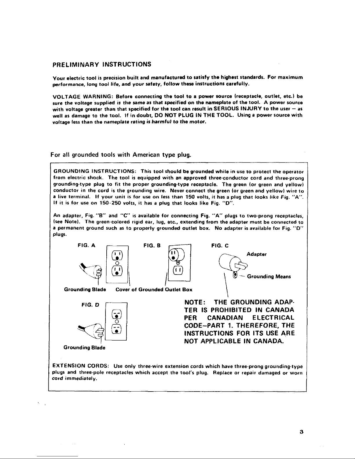
For
all
grounded
tools
with
American type plug.
GROUNDING INSTRUCTIONS: This tool should be grounded while
in
use to protect
the
operator
from electric shock. The tool
is
equipped with an approved three-conductor cord and threeprong
grounding-type plug to fit the proper grounding-type receptacle. The green (or green and yellow)
conductor
in
the
cord
is
the grounding wire. Never connect the green (or green and yellow) wire to
a live terminal. If your unit
is
for use
on
less than
150
volts,
it
has a plug that looks like Fig.
"A".
It
it
is
for ure on
150-250
volts, it has a plug that
looks
like Fig.
"D".
An adapter, Fig. "B" and
"C'
is
available for connecting Fig.
"A'
plugs to two-prong receptacles,
(see Note). The green-colored rigid ear, lug, etc., extending from the adapter must be connected to
a permanent ground such as to properly grounded outlet box.
No adapter
is
available for Fig.
"D"
plugs.
\
Grounding Blade
Cover' of Grounded Outlet Box
FIG.
D
NOTE: THE GROUNDING ADAP-
TER
IS
PROHIBITED IN CANADA
PER
CANADIAN ELECTRICAL
INSTRUCTIONS FOR ITS USE ARE
NOT APPLICABLE IN CANADA.
CODE-PART
1.
THEREFORE, THE
Grounding Blade
EXTENSION
CORDS:
Use
only three-wire extension cords which have three-prong grounding-type
plugs and three-pole receptacles which accept the tool's plug.
Replace or repair damaged or worn
:ord immediately.
3
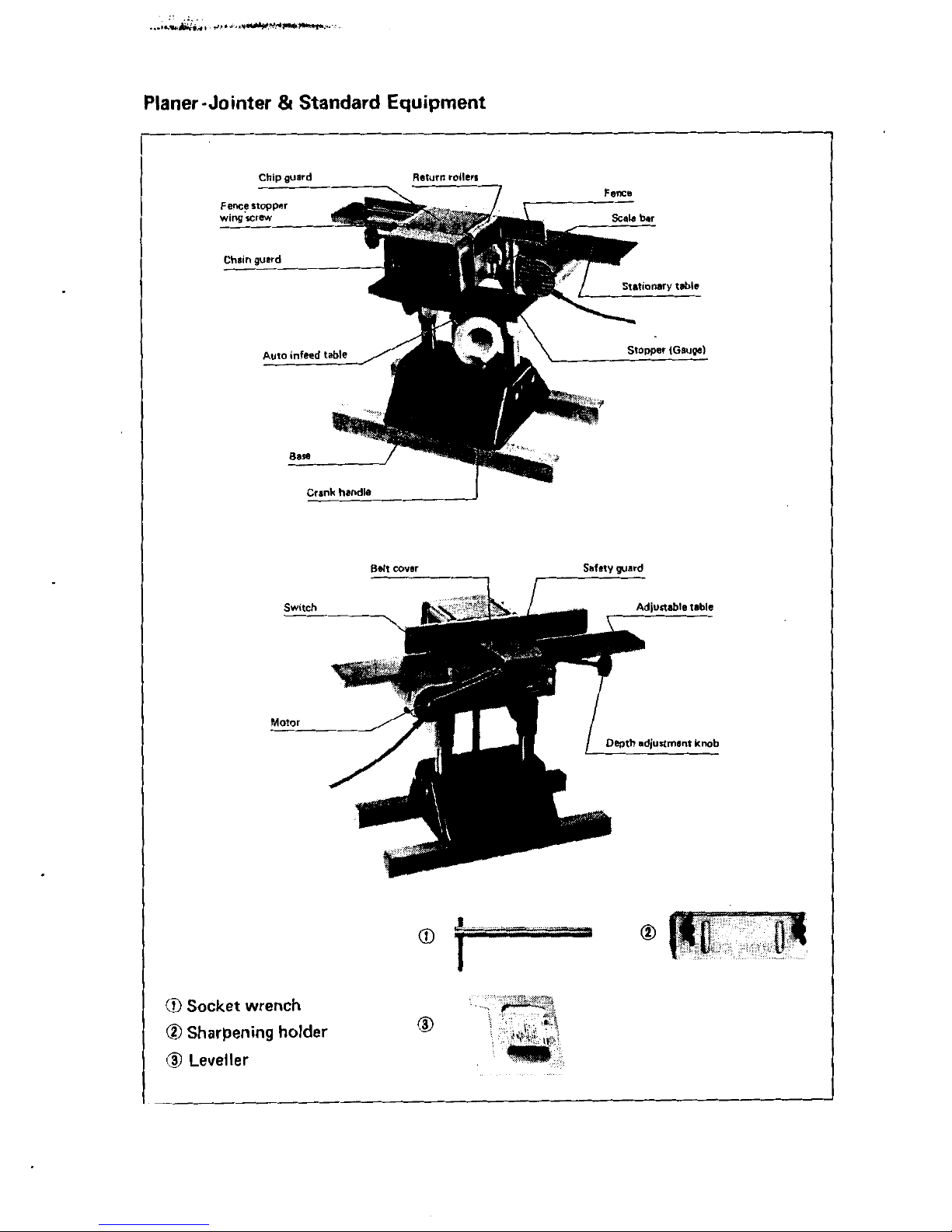
Crank
handle
I
safety
guard
Belt
cover
------lI
0
Socket wrench
0
Sharpening holder
@
Leveller
0
I
Special Precautions with Planer- Jointer
a.
Jointing Operations
Do
not perform jointing operations on material shorter than
4-3/8
inches
(110
mm),
narrower than
314
inch
(19
mm), or
less
than
1/4
inch
(6.4
mm) thick.
Do
not perform planing operations on material shorter than
4-3/8
inches
(110
mm),
narrower than
3/4
inch
(19
mm), wider than
5-1/4
inches
(132
mm)
in auto feed and
5-1/4
inches
(132
mm) in manual infeed or thinner than
1/2
inch
(12.7
mm).
c.
Maintain the proper relationships of infeed and outfeed table surfaces and cutter head
b.
Planing Operations
knife path.
d. Support the workpiece adequately
at
all
times during operation; maintain control of
the work
at
all
times.
e.
Do
not back the work toward the infeed table.
f.
Do
not attempt to perform an abnormal or little-used operation without study and the
use
of
adequate holddown/push blocks, jigs, fixtures, stops, etc.
HOW
TO
USE
I
Forthe Planer
1
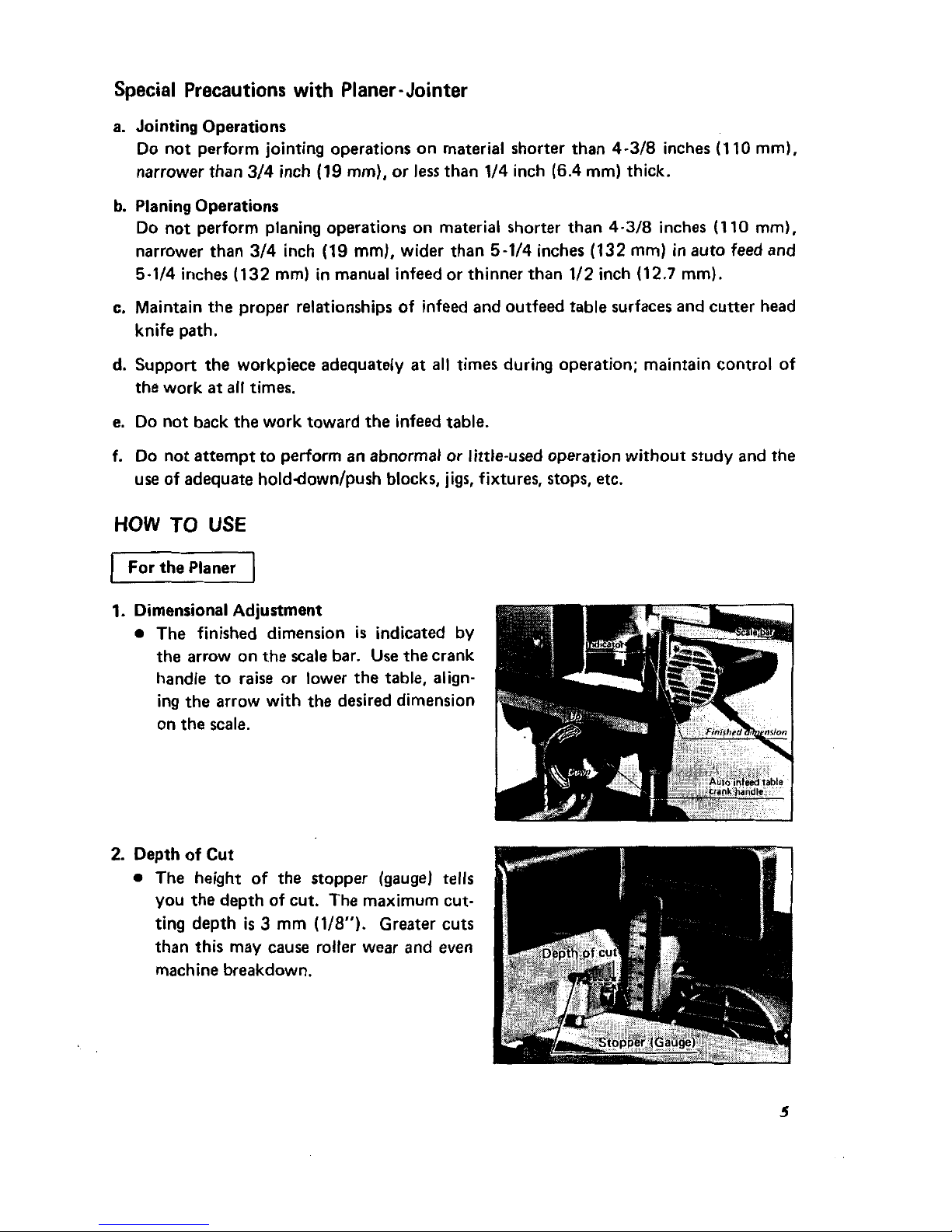
1.
Dimensional Adjustment
0
The finished dimension
is
indicated by
the arrow on the scale bar.
Use
the crank
handle to raise or lower the table, aligning the arrow with the desired dimension
on the scale.
2.
Depth
of
Cut
0
The height
of
the stopper (gaugej
tells
you the depth of cut. The maximum cutting depth
is
3
mm
(1/8").
Greater cuts
than this may cause roller wear and even
machine breakdown.
5
 Loading...