

Makita PLANER 2040 Instruction Manual
Planer
1
mm
11/32")
of
stock
wtdth
over
304
mmll 1-314")
3
mm
1118"l
of
stock
width
under
150
mm
15-718")
Max.
srock
height
No
load
speed
12.7
mm
-
195mm
6,500
,,,,
In,
1112"
-
7-518")
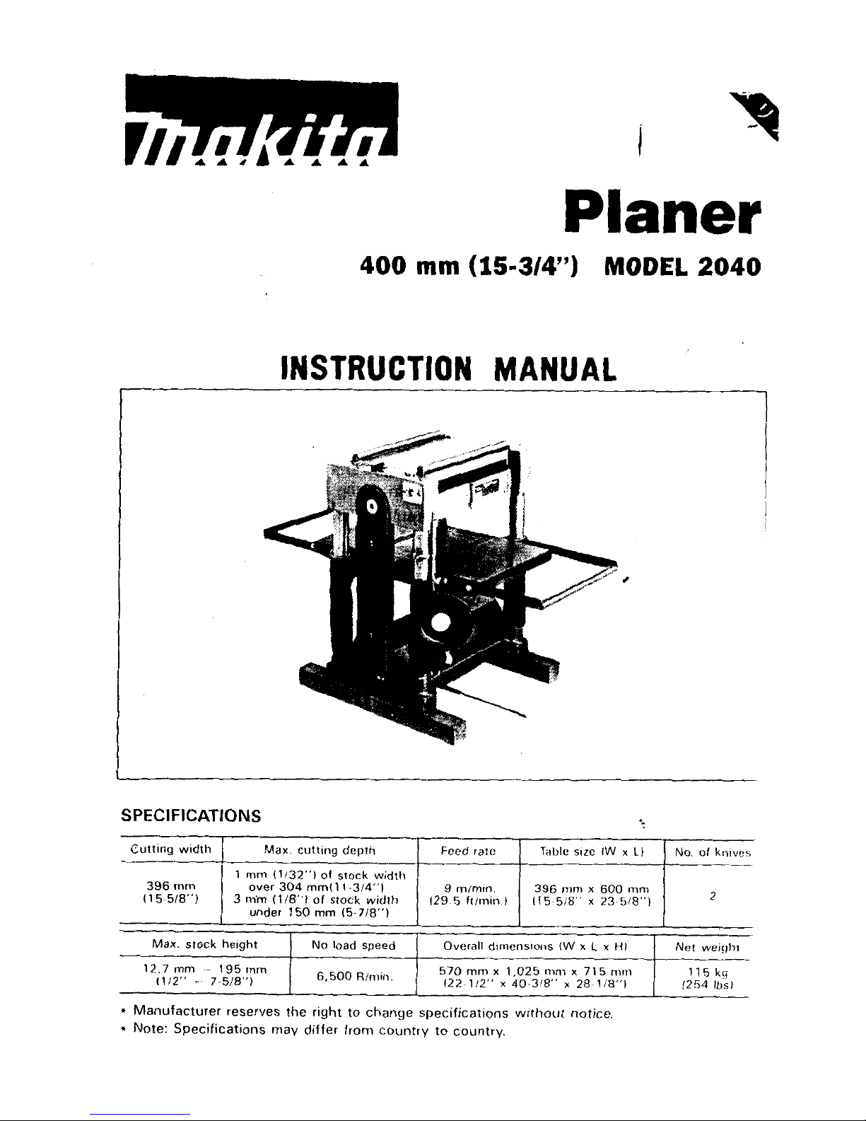
400
mm
(15-3/4")
MODEL
2040
2
9
m/mm
129
5
ftimin.1
396
mm
x
600
nim
115 5/8"
x
23
5/8"1
Overall
dimenslons
(W
x
L
x
HI
570
mm
x
1,025
111111
x
715
rnnl
Net
weight
115
kg
(254
Ibsl
122
112"
x
40.318''
x
28
118"l
INSTRUCTION
MANUAL
SPEC
IF I CAT
IONS
396
mm
I1
5~518")

For Your Own Safety Read Instruction
Manual Before Operating Planer
GENERAL SAFETY PRECAUTIONS
(For
All
Tools)
1.
KNOW YOUR POWER TOOL. Read the owner's manual carefully. Learn the
tools applications and limitations, as well as the specific potential hazards
peculiar to
it.
2.
KEEP GUARDS IN PLACE and
in
working order.
3.
REMOVE ADJUSTING KEYS AND WRENCHES. Form habit of checking to
see that keys and adjusting wrenches are removed from tool before turning
it
on.
4.
KEEP WORK AREA CLEAN. Cluttered areas and benches invite accidents.
5. DON'T USE IN DANGEROUS ENVIRONMENT. Don't use power tools
in
damp
or
wet locations, or expose them to rain. Keep work area well lighted.
6.
KEEP CHILDREN AWAY. All visitors should be kept safe distance from work
area.
7.
MAKE WORKSHOP KID
PROOF
with padlocks, master switches, or by
removing starter keys.
8.
DON'T FORCE TOOL.
It
will do the job better and safer at the rate for which
it
was designed.
9.
USE RIGHT TOOL. Don't force tool or attachment to do a job for which
it
was not designed.
10.
WEAR PROPER APPAREL. Wear no
loose
clothing, gloves, neckties, rings,
bracelets, or other jewelry which may get caught
in
moving parts. Nonslip
footwear is recommended. Wear protective hair covering to contain long hair.
11.
ALWAYS USE SAFETY GLASSES. Also use face or dust mask
if
cutting operation is dusty. Everyday eyeglasses only have impact resistant lenses, they
are NOT safety glasses.
12.
SECURE WORK. Use clamps or a vise to hold work when practical. It's safer
than using your hand and
it
frees both hands to operate tool.
13.
DON'T OVERREACH. Keep proper footing and balance at all times.
14.
MAINTAIN TOOLS WITH CARE. Keep tools sharp and clean for best and
safest performance. Follow instructions for lubricating and changing accessories.
15. DISCONNECT TOOLS before servicing; when changing accessories such as
blades, bits, cutters, and the like.
"
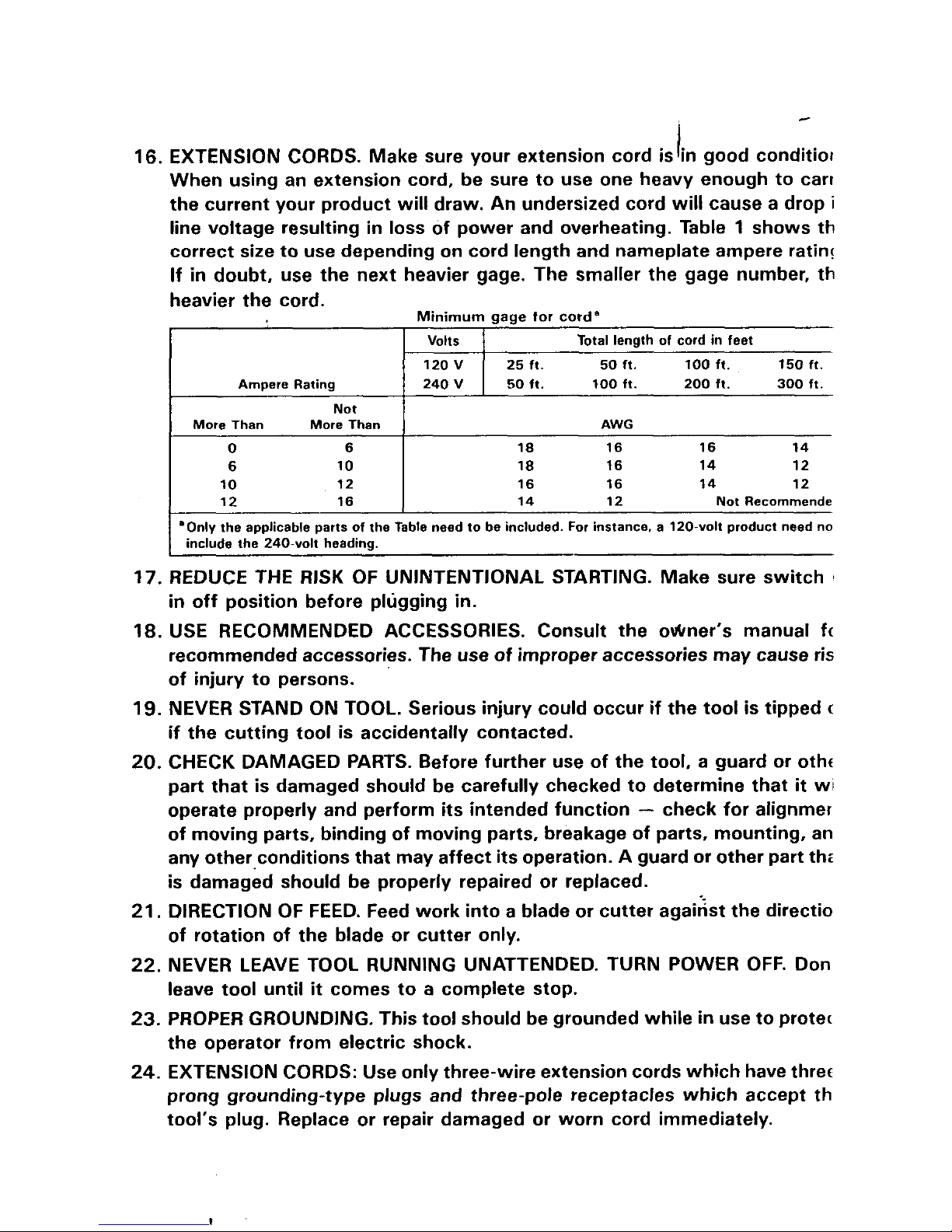
Ampere Rating
Not
More Than More Than
0
6
6 10
10 12
12 16
Volts
12OV 25ft. 50ft. 100ft. 150
ft.
240V 5011. 100 ft. 200 ft.
300
ft.
Total length of cord in feet
AWG
18 16 16 14
18 16 14 12
16 16 14 12
14 12 Not Recommende
'Only the applicable parts of the Table need to be included. For instance. a 120-volt product need no
I
include the 240-volt headina.
17. REDUCE THE RISK OF UNINTENTIONAL STARTING. Make sure switch
in
off position before plugging
in.
18.
USE RECOMMENDED ACCESSORIES. Consult the owner's manual fc
recommended accessories. The use of improper accessories may cause ris
of injury to persons.
19.
NEVER STAND ON TOOL. Serious injury could occur
if
the tool is tipped
c
if
the cutting tool is accidentally contacted.
20.
CHECK DAMAGED PARTS. Before further use of the tool, a guard or otht
part that is damaged should be carefully checked to determine that
it
wi
operate properly and perform its intended function
-
check for alignmer
of moving parts, binding of moving parts, breakage of parts, mounting, an
any other.conditions that may affect its operation. A guard or other part
thc
is damaged should be properly repaired or replaced.
21.
DIRECTION OF FEED. Feed work into a blade or cutter against the directio
of rotation of the blade or cutter only.
22.
NEVER LEAVE TOOL RUNNING UNATTENDED. TURN POWER OFF. Don
leave tool
until
it
comes to a complete stop.
23.
PROPER GROUNDING. This tool should be grounded while
in
use to protec
the operator from electric shock.
24.
EXTENSION CORDS: Use only three-wire extension cords which have threr
prong grounding-type plugs and three-pole receptacles which accept th
tool's plug. Replace or repair damaged or worn cord immediately.
I
3LTAGE WARNING: Before connecting the tool to a power source (receptacle,
Itlet, etc.) be sure the voltage supplied is the same as that specified on the
meplate of the tool. A power source
)r the tool can result
le tool. If
in
doubt, DO NOT PLUG IN THE TOOL. Using a power source
in
SERIOUS INJURY to the user - as well as damage to
with
voltage greater than that specified
with
oltage less than the nameplate rating is harmful to the motor.
;ROUNDING INSTRUCTIONS
\LL GROUNDED, CORD-CONNECTED
TOOLS:
In
the event of a malfunction or
Breakdown, giounding provides a path of least resistance for electric current to
educe the risk of electric shock. This tool is equipped with an electric cord having
an
equipment-grounding conductor and a grounding plug. The
ilugged into a matching outlet that is properly installed and grounded
plug
must be
in
ac-
zordance with all local codes and ordinances.
Do
not modify the
plug
provided-if
it
will
not fit the outlet, have the proper
outlet installed by a qualified electrician.
in
Improper connection of the equipment-grounding conductor can result
of electric shock. The conductor
is
green with or without yellow stripes is the equipment-grounding conductor.
If
repair or replacement of
the
with
insulation having an outer surface that
electric cord or plug is necessary, do not connect
a risk
the equipment-grounding conductor to a live terminal.
Check with a qualified electrician or serviceman if the grounding instructions
are not completely understood, or if
in
doubt as to whether the tool is properly
grounded.
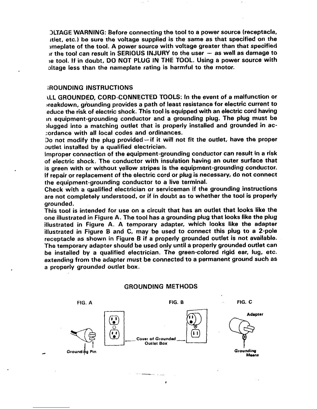
This tool is intended for use on a circuit that has an outlet that looks like the
one illustrated
illustrated
illustrated
receptacle as shown
The temporary adapter should be used only
be installed by a qualified electrician. The green-colored rigid ear,
in
Figure A. The tool has a grounding
in
Figure A.
in
Figure B and C, may be used
A
temporary adapter, which looks like the adapter
in
Figure B if a properly grounded outlet is not available.
plug
that looks like the
to
connect this
until
a properly grounded outlet can
plug
to a 2-pole
lug,
plug
etc.
extending from the adapter must be connected to a permanent ground such as
a properly grounded outlet box.
FIG.
A
Groundibg
Pin
GROUNDING METHODS
FIG.
B
--
I
~
FIG.
C
Grounding
Munl
ADDITIONAL
SAFETY
RULES
1.
Wear eye protection.
2. Never perform planing operation with drive guard removed.
3.
Do not perform planing operations on material shorter than (a dimension
equal to the cutter head length plus 2 inches), narrower than
314
inch, or
wider than (the cutter capacity
in
inches) or thinner than
1/2
inch.
4.
Don't use the tool
in
presence of flammable liquids or gases.
5.
Handle the blades very carefully.
6. Check the blades carefully for cracks or damage before operation. Replace
7.
Be sure the planer blade installation bolts are securely tightened before
8.
Sharpen both blades evenly, or replace both blades or both cutterhead covers
9.
Remove nails and clean the workpiece before cutting. Nail, sand or other
10.
Make sure
the
blade is not contacting workpiece before
the
switch is turned
11.
Wait
until
the blades attain full speed before cutting.
12.
Keep hands away from rotating parts.
13. Don't back the workpiece toward the infeed table.
14.
Two or more pieces of narrow but similar thickness stock can be passed
through the auto-planer side by side.
However, allow some spacing between the stock to permit the feed rollers
to grip the thinnest piece.
Otherwise, a slightly thinner piece could be kicked back by the cutterhead.
15. Stop operation immediately if you notice anything abnormal.
16. Always switch off and wait for blades to come to a complete stop before
17.
Never stick your finger into
the
chip chute. Chute may jam when cutting
18. Don't touch blades right after operation, they may be extremely hot and could
19.
Don't abuse cord. Never yank cord to disconnect from receptacle. Keep cord
cracked
or
damaged blades immediately.
operating.
at the same time.
matter can cause blade damage.
on.
adjusting any parts, cleaning out chips or approaching the blade.
damp wood. Turn off the planer and then clean out chips with a stick.
burn your skin.
from heat,
oil
and sharp edges.
SAVE THESE INSTRUCTIONS.
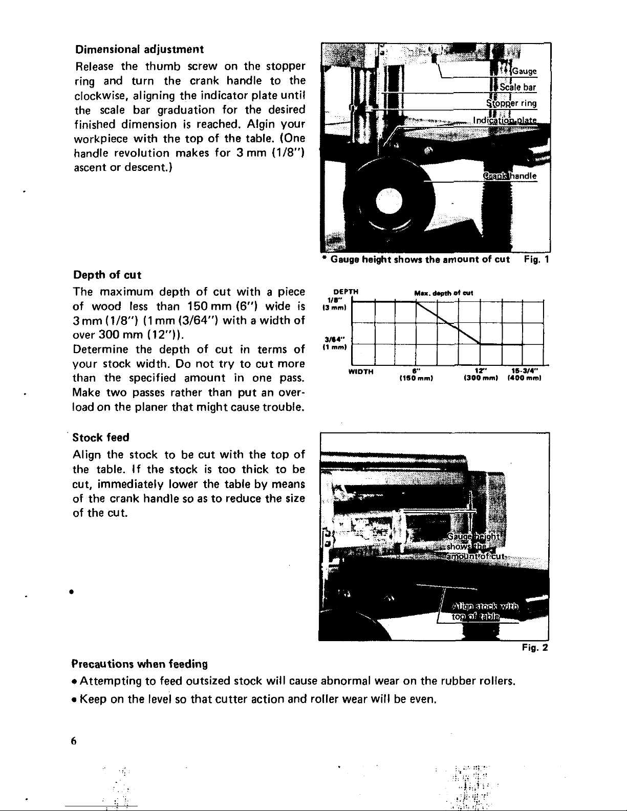
the scale bar graduation for the desired
finished dimension
is
reached. Algin your
workpiece with the top of the table. (One
handle revolution makes for
3
mm
(1/8")
ascent or descent.)
Depth of cut
The maximum depth of cut with
a
piece
of wood
less
than
150
mm
(6")
wide
is
3
mm
(1/8") (1
mm
(3/64")
with a width of
over
300
mm
(1
2")).
Determine the depth of cut in terms of
your stock width.
Do
not try to
cut
more
than the specified amount in one pass.
Make two passes rather than put an overload on the planer that might cause trouble.
Gauge height shows the amount
of
cut Fig.
1
OEP
118-
I3
mml
3m4"
11
mml
c'
1I'
16-314"
1150
mml
1300
mml
1400mml
WIDTH
Stock feed
Align the stock to be cut with the top
of
the table. If the stock
is
too thick to be
cut, immediately lower the table by means
of
the
crank handle
so
as
to reduce
the
size
of the cut.
Fig.
:
Precautions when feeding
*Attempting to feed outsized stock will cause abnormal wear on the rubber rollers.
Keep on the
level
so
that cutter action and roller wear will be even.
6
 Loading...