

Makita PH02 Instruction Manual
INSTRUCTION MANUAL
MANUEL D'INSTRUCTION
MANUAL DE INSTRUCCIONES
Cordless Hammer Driver Drill
Perceuse Percussion-Visseuse
sans Fil
Rotomartillo Atornillador
Inalámbrico
PH01
PH02
IMPORTANT: Read Before Using.
IMPORTANT : Lire avant usage.
IMPORTANTE: Lea antes de usar.

ENGLISH (Original instructions)
SPECIFICATIONS
Model PH01 PH02
Capacities Masonry 10 mm (3/8") 13 mm (1/2")
Steel 10 mm (3/8") 13 mm (1/2")
Wood 25 mm (1") 36 mm (1-7/16")
Wood screw 5.1 mm x 63 mm
Machine screw 6 mm (1/4")
No load speed (RPM) High (2) 0- 1,400 /min
Low (1) 0 - 400 /min
Blows per minute High (2) 0 - 21,000
Low (1) 0 - 6,000
Overall length 216 mm (8-1/2") 246 mm (9-11/16")
Net weight 1.5 kg (3.3lbs) 1.7 kg (3.8lbs)
Rated voltage D.C. 14.4 V D.C. 18 V
Standard battery cartridges BL1411G / BL1413G /
• Due to our continuing programme of research and development, the specications herein are subject to change
without notice.
• Specications and battery cartridge may differ from country to country.
• Weight, with battery cartridge, according to EPTA-Procedure 01/2003
General Power Tool Safety Warnings
WARNING Read all safety warnings and all instruc-
tions. Failure to follow the warnings and instructions may
result in electric shock, re and/or serious injury.
Save all warnings and instructions for future reference.
The term "power tool" in the warnings refers to your
mains-operated (corded) power tool or battery-operated
(cordless) power tool.
Work area safety
1. Keep work area clean and well lit. Cluttered or
dark areas invite accidents.
2. Do not operate power tools in explosive atmo-
spheres, such as in the presence of ammable
liquids, gases or dust. Power tools create sparks
which may ignite the dust or fumes.
3. Keep children and bystanders away while
operating a power tool. Distractions can cause
you to lose control.
Electrical safety
4.
Power tool plugs must match the outlet. Never modify
the plug in any way. Do not use any adapter plugs with
earthed (grounded) power tools. Unmodied plugs and
matching outlets will reduce risk of electric shock.
5. Avoid body contact with earthed or grounded
surfaces such as pipes, radiators, ranges and
refrigerators. There is an increased risk of elec-
tric shock if your body is earthed or grounded.
6. Do not expose power tools to rain or wet con-
ditions. Water entering a power tool will increase
the risk of electric shock.
2 ENGLISH
(13/64" x 2-1/2")
BL1415G
7. Do not abuse the cord. Never use the cord for
carrying, pulling or unplugging the power tool.
Keep cord away from heat, oil, sharp edges
or moving parts. Damaged or entangled cords
increase the risk of electric shock.
8.
When operating a power tool outdoors, use an
extension cord suitable for outdoor use. Use of a cord
suitable for outdoor use reduces the risk of electric shock.
9. If operating a power tool in a damp location is
unavoidable, use a ground fault circuit interrupter (GFCI) protected supply. Use of an GFCI
reduces the risk of electric shock.
Personal safety
10. Stay alert, watch what you are doing and use
common sense when operating a power tool.
Do not use a power tool while you are tired or
under the inuence of drugs, alcohol or medication. A moment of inattention while operating
power tools may result in serious personal injury.
11. Use personal protective equipment. Always
wear eye protection. Protective equipment such
as dust mask, non-skid safety shoes, hard hat, or
hearing protection used for appropriate conditions
will reduce personal injuries.
12. Prevent unintentional starting. Ensure the
switch is in the off-position before connecting
to power source and/or battery pack, picking
up or carrying the tool. Carrying power tools with
your nger on the switch or energising power tools
that have the switch on invites accidents.
13. Remove any adjusting key or wrench before
turning the power tool on. A wrench or a key left
attached to a rotating part of the power tool may
result in personal injury.
6 mm x 75 mm (1/4" x 2-15/16")
BL1811G / BL1813G /
BL1815G

14. Do not overreach. Keep proper footing and
balance at all times. This enables better control
of the power tool in unexpected situations.
15. Dress properly. Do not wear loose clothing or
jewellery. Keep your hair, clothing, and gloves
away from moving parts. Loose clothes, jewel-
lery or long hair can be caught in moving parts.
16. If devices are provided for the connection of
dust extraction and collection facilities, ensure
these are connected and properly used. Use of
dust collection can reduce dust-related hazards.
Power tool use and care
17. Do not force the power tool. Use the correct
power tool for your application. The correct
power tool will do the job better and safer at the
rate for which it was designed.
18.
Do not use the power tool if the switch does not turn
it on and off. Any power tool that cannot be controlled
with the switch is dangerous and must be repaired.
19. Disconnect the plug from the power source
and/or the battery pack from the power tool
before making any adjustments, changing
accessories, or storing power tools. Such pre-
ventive safety measures reduce the risk of starting
the power tool accidentally.
20. Store idle power tools out of the reach of chil-
dren and do not allow persons unfamiliar with
the power tool or these instructions to operate
the power tool. Power tools are dangerous in the
hands of untrained users.
21. Maintain power tools. Check for misalignment
or binding of moving parts, breakage of parts
and any other condition that may affect the
power tool’s operation. If damaged, have the
power tool repaired before use. Many accidents
are caused by poorly maintained power tools.
22. Keep cutting tools sharp and clean. Properly
maintained cutting tools with sharp cutting edges
are less likely to bind and are easier to control.
23. Use the power tool, accessories and tool bits
etc. in accordance with these instructions, taking into account the working conditions and
the work to be performed. Use of the power tool
for operations different from those intended could
result in a hazardous situation.
Battery tool use and care
24. Recharge only with the charger specied by
the manufacturer. A charger that is suitable for
one type of battery pack may create a risk of re
when used with another battery pack.
25. Use power tools only with specically desig-
nated battery packs. Use of any other battery
packs may create a risk of injury and re.
26. When battery pack is not in use, keep it away
from other metal objects, like paper clips,
coins, keys, nails, screws or other small metal
objects, that can make a connection from one
terminal to another. Shorting the battery termi-
nals together may cause burns or a re.
27. Under abusive conditions, liquid may be
ejected from the battery; avoid contact. If con-
tact accidentally occurs, ush with water. If
liquid contacts eyes, additionally seek medical
help. Liquid ejected from the battery may cause
irritation or burns.
Service
28. Have your power tool serviced by a qualied
repair person using only identical replacement
parts. This will ensure that the safety of the power
tool is maintained.
29. Follow instruction for lubricating and chang-
ing accessories.
30. Keep handles dry, clean and free from oil and
grease.
CORDLESS HAMMER DRILL
SAFETY WARNINGS
1. Wear ear protectors with impact drills.
Exposure to noise can cause hearing loss.
2. Use auxiliary handles supplied with the tool.
Loss of control can cause personal injury. (if
supplied)
3. Hold power tools by insulated gripping sur-
faces when performing an operation where
the cutting tool may contact hidden wiring or
its own cord. Contact with a "live" wire will make
exposed metal parts of the tool "live" and shock
the operator.
4. Hold power tool by insulated gripping sur-
faces, when performing an operation where
the fastener may contact hidden wiring or its
own cord. Fasteners contacting a "live" wire may
make exposed metal parts of the power tool "live"
and could give the operator an electric shock.
5. Always be sure you have a rm footing.
Be sure no one is below when using the tool in
high locations.
6. Hold the tool rmly.
7. Keep hands away from rotating parts.
8. Do not leave the tool running. Operate the tool
only when hand-held.
9. Do not touch the drill bit or the workpiece
immediately after operation; they may be
extremely hot and could burn your skin.
10. Some material contains chemicals which may
be toxic. Take caution to prevent dust inhalation and skin contact. Follow material supplier
safety data.
SAVE THESE INSTRUCTIONS.
WARNING: DO NOT let comfort or famil-
iarity with product (gained from repeated
use) replace strict adherence to safety
rules for the subject product. MISUSE or
failure to follow the safety rules stated in
this instruction manual may cause serious
personal injury.
Symbols
The followings show the symbols used for tool.
volts
direct current
3 ENGLISH
no load speed
revolutions or reciprocation per minute
FUNCTIONAL
DESCRIPTION
number of blow
IMPORTANT SAFETY
INSTRUCTIONS
FOR BATTERY CARTRIDGE
1. Before using battery cartridge, read all instructions and cautionary markings on (1) battery
charger, (2) battery, and (3) product using
battery.
2. Do not disassemble battery cartridge.
3. If operating time has become excessively
shorter, stop operating immediately. It may
result in a risk of overheating, possible burns
and even an explosion.
4. If electrolyte gets into your eyes, rinse them
out with clear water and seek medical attention right away. It may result in loss of your
eyesight.
5. Do not short the battery cartridge:
(1) Do not touch the terminals with any con-
ductive material.
(2) Avoid storing battery cartridge in a con-
tainer with other metal objects such as
nails, coins, etc.
(3) Do not expose battery cartridge to water
or rain.
A battery short can cause a large current
ow, overheating, possible burns and even a
breakdown.
6. Do not store the tool and battery cartridge in
locations where the temperature may reach or
exceed 50°C (122°F).
7. Do not incinerate the battery cartridge even if
it is severely damaged or is completely worn
out. The battery cartridge can explode in a re.
8. Be careful not to drop or strike battery.
9. Do not use a damaged battery.
SAVE THESE INSTRUCTIONS.
Tips for maintaining maximum
battery life
1. Charge the battery cartridge before completely
discharged.
Always stop tool operation and charge the battery cartridge when you notice less tool power.
2. Never recharge a fully charged battery cartridge.
Overcharging shortens the battery service life.
3. Charge the battery cartridge with room temperature at 10°C - 40°C (50°F - 104°F). Let a hot
battery cartridge cool down before charging it.
CAUTION:
• Always be sure that the tool is switched off and
the battery cartridge is removed before adjust-
ing or checking function on the tool.
Installing or removing battery
cartridge
1
2
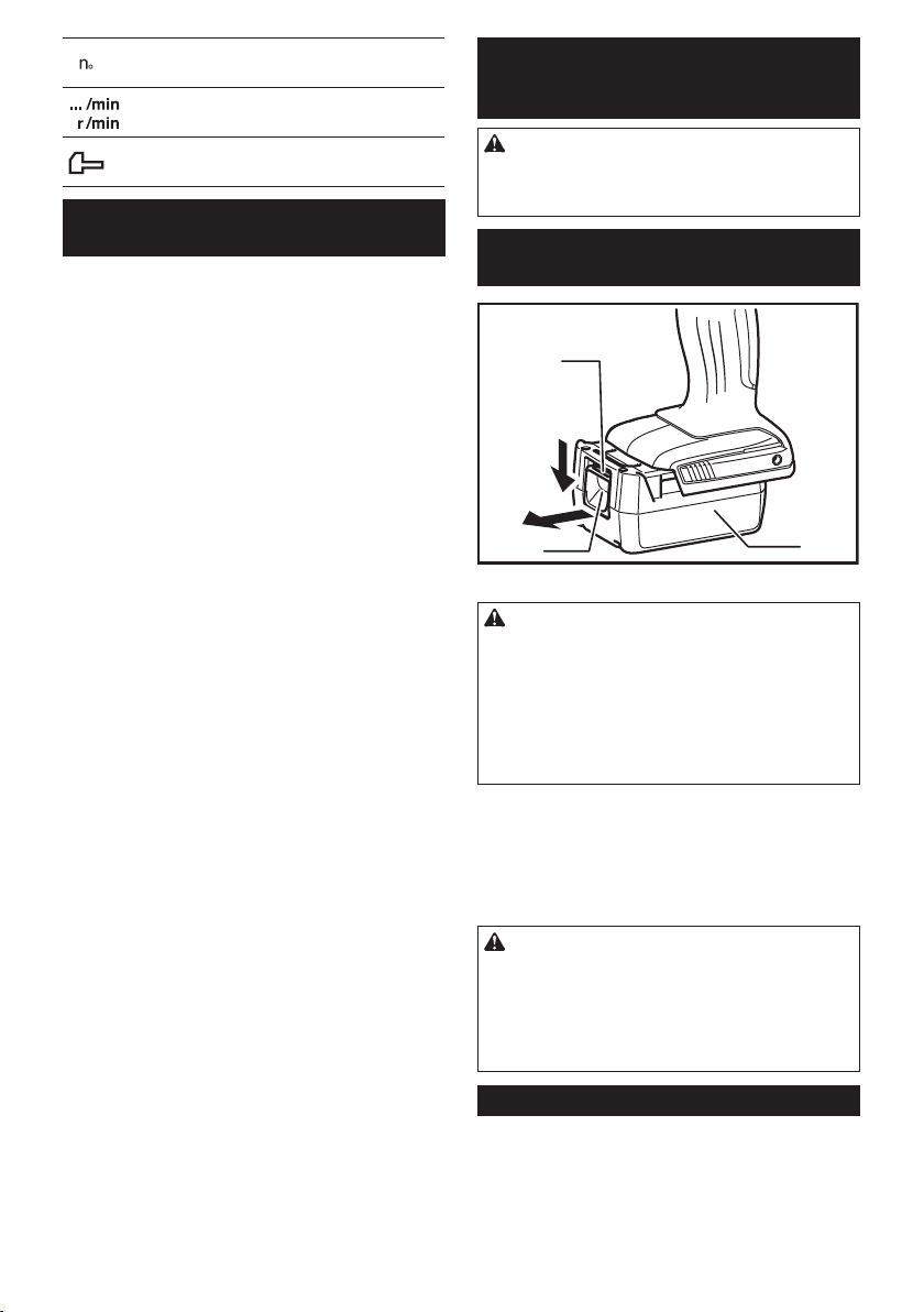
► 1. Red indicator 2. Button 3. Battery cartridge
CAUTION:
• Always switch off the tool before installing or
removing of the battery cartridge.
• Hold the tool and the battery cartridge rmly
when installing or removing battery cartridge. Failure to hold the tool and the battery
cartridge rmly may cause them to slip off your
hands and result in damage to the tool and
battery cartridge and a personal injury.
To remove the battery cartridge, slide it from the tool
while sliding the button on the front of the cartridge.
To install the battery cartridge, align the tongue on the
battery cartridge with the groove in the housing and slip
it into place. Insert it all the way until it locks in place
with a little click. If you can see the red indicator on the
upper side of the button, it is not locked completely.
CAUTION:
•
Always install the battery cartridge fully until the red indi-
cator cannot be seen. If not, it may accidentally fall out of
the tool, causing injury to you or someone around you.
• Do not install the battery cartridge forcibly. If the
cartridge does not slide in easily, it is not being
inserted correctly.
Battery protection system
The battery cartridge is equipped with the protection
system, which automatically cuts off the output power
for its long service life.
The tool stops during operation when the tool and/or
battery are placed under the following situation. This is
caused by the activation of protection system and does
not show the tool trouble.
4 ENGLISH
3
• When the tool is overloaded:
At this time, release the switch trigger,
remove the battery cartridge and remove
causes of overload and then pull the switch
trigger again to restart.
• When battery cells get hot:
If any operation of the switch trigger, the
motor will remain stopped. At this time, stop
use of the tool and cool the battery cartridge.
• When the remaining battery capacity gets low:
If you pull the switch trigger, the motor runs
again but stops soon. In this case, to prevent
over discharge, remove the battery cartridge
from the tool and charge it
Switch action
1
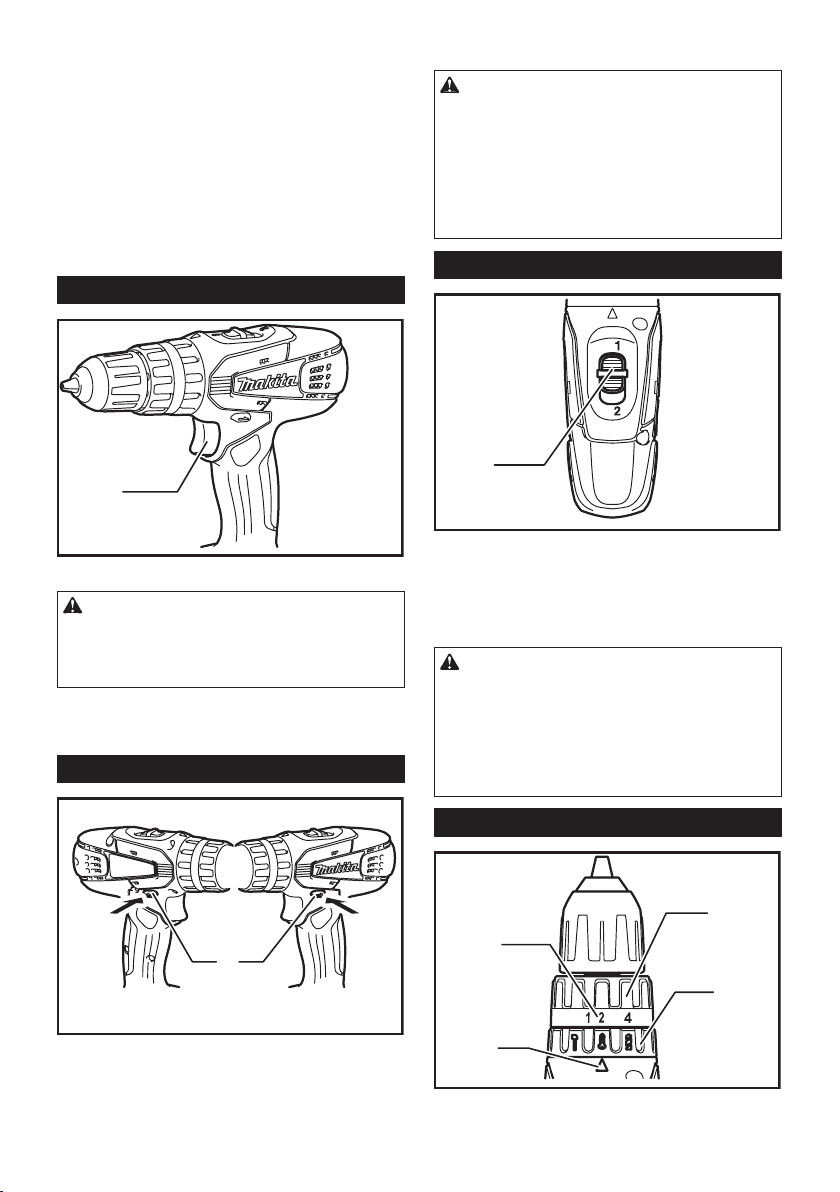
► 1. Switch trigger
CAUTION:
• Before inserting the battery cartridge into the
tool, always check to see that the switch trigger
actuates properly and returns to the "OFF"
position when released.
To start the tool, simply pull the switch trigger. Tool
speed is increased by increasing pressure on the switch
trigger. Release the switch trigger to stop.
Reversing switch action
When the reversing switch lever is in the neutral position, the switch trigger cannot be pulled.
CAUTION:
• Always check the direction of rotation before
operation.
• Use the reversing switch only after the tool
comes to a complete stop. Changing the direction of rotation before the tool stops may damage the tool.
• When not operating the tool, always set the
reversing switch lever to the neutral position.
Speed change
1
► 1. Speed change lever
To change the speed, rst switch off the tool and then
slide the speed change lever to the "2" side for high
speed or "1" side for low speed. Be sure that the speed
change lever is set to the correct position before opera-
tion. Use the right speed for your job.
CAUTION:
• Always set the speed change lever fully to the
correct position. If you operate the tool with the
speed change lever positioned halfway between
the "1" side and "2" side, the tool may be
damaged.
• Do not use the speed change lever while the
tool is running. The tool may be damaged.
A
B
1
► 1. Reversing switch lever
This tool has a reversing switch to change the direction
of rotation. Depress the reversing switch lever from the
A side for clockwise rotation or from the B side for counterclockwise rotation.
Selecting the action mode
1
3
2
4
► 1. Adjusting ring 2. Action mode changing ring
3. Graduation 4. Arrow
5 ENGLISH
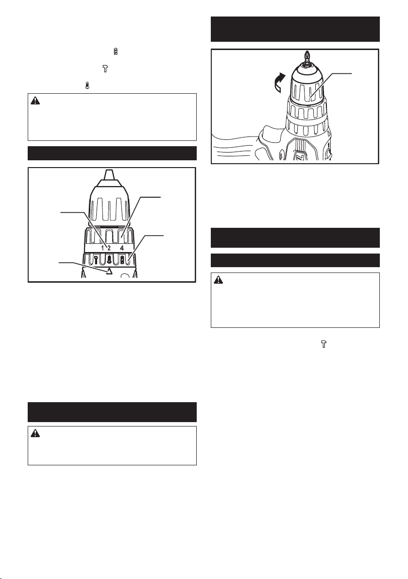
This tool employs an action mode changing ring. Select
one of the three modes suitable for your work needs by
using this ring.
For rotation only, turn the ring so that the arrow on the
tool body points toward the
For rotation with hammering, turn the ring so that the
arrow points toward the mark on the ring.
For rotation with clutch, turn the ring so that the arrow
points toward the mark on the ring.
mark on the ring.
CAUTION:
• Always set the ring correctly to your desired
mode mark. If you operate the tool with the ring
positioned halfway between the mode marks,
the tool may be damaged.
Adjusting the fastening torque
1
3
Installing or removing driver bit or
drill bit
1
► 1. Sleeve
Turn the sleeve counterclockwise to open the chuck
jaws. Place the bit in the chuck as far as it will go. Turn
the sleeve clockwise to tighten the chuck.
To remove the bit, turn the sleeve counterclockwise.
2
4
► 1. Adjusting ring 2. Action mode changing ring
3. Graduation 4. Arrow
The fastening torque can be adjusted in 16 steps by
turning the adjusting ring so that its graduations are
aligned with the arrow on the tool body. The fastening
torque is minimum when the number 1 is aligned with
the arrow, and maximum when the number 16 is aligned
with the arrow.
Before actual operation, drive a trial screw into your
material or a piece of duplicate material to determine which torque level is required for a particular
application.
ASSEMBLY
CAUTION:
• Always be sure that the tool is switched off and
the battery cartridge is removed before carrying
out any work on the tool.
OPERATION
Hammer drilling operation
CAUTION:
• There is a tremendous and sudden twisting
force exerted on the tool/bit at the time of hole
break-through, when the hole becomes clogged
with chips and particles, or when striking reinforcing rods embedded in the concrete.
First, turn the action mode changing ring so that the
arrow on the tool body points to the marking. The
adjusting ring can be aligned in any torque levels for
this operation.
Be sure to use a tungsten-carbide tipped bit.
Position the bit at the desired location for the hole, then
pull the switch trigger. Do not force the tool. Light pressure gives best results. Keep the tool in position and
prevent it from slipping away from the hole.
Do not apply more pressure when the hole becomes
clogged with chips or particles. Instead, run the tool at
an idle, then remove the bit partially from the hole. By
repeating this several times, the hole will be cleaned out
and normal drilling may be resumed.
6 ENGLISH
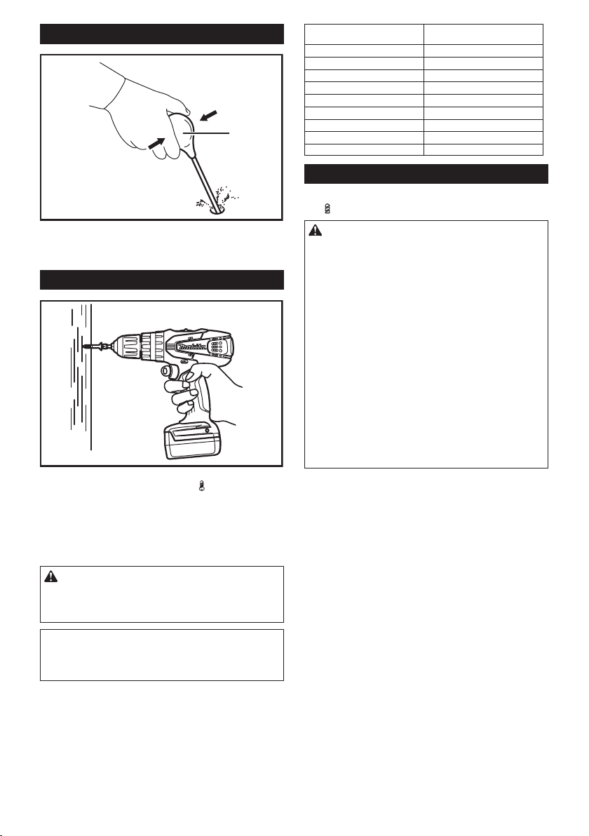
Blow-out bulb (optional accessory)
4.2 - 4.4 (11/64” - 11/64”)
6.1 (15/64”)
1
► 1. Blow-out bulb
After drilling the hole, use the blow-out bulb to clean the
dust out of the hole.
Screwdriving operation
First, turn the action mode changing ring so that the
arrow on the tool body points to the marking. Adjust
the adjusting ring to the proper torque level for your
work. Then proceed as follows.
Place the point of the driver bit in the screw head and
apply pressure to the tool. Start the tool slowly and then
increase the speed gradually. Release the switch trigger
as soon as the clutch cuts in.
CAUTION:
• Make sure that the driver bit is inserted straight
in the screw head, or the screw and/or bit may
be damaged.
NOTE:
• When driving wood screws, predrill pilot holes
to make driving easier and to prevent splitting of
the workpiece. See the chart.
Nominal diameter of wood screw
(mm)
3.1 (1/8”)
3.5 (9/64”)
3.8 (5/32”)
4.5 (11/64”)
4.8 (3/16”)
5.1 (13/64”)
5.5 (7/32”)
5.8 (7/32”)
Recommended size of pilot hole
(mm)
2.0 - 2.2 (5/64” - 3/32”)
2.2 - 2.5 (3/32” - 3/32”)
2.5 - 2.8 (3/32” - 7/64”)
2.9 - 3.2 (7/64” - 1/8”)
3.1 - 3.4 (1/8” - 9/64”)
3.3 - 3.6 (1/8” - 9/64”)
3.7 - 3.9 (9/64” - 5/32”)
4.0 - 4.2 (5/32” - 11/64”)
Drilling operation
First, turn the adjusting ring so that the pointer points to
the marking. Then proceed as follows.
CAUTION:
• Pressing excessively on the tool will not speed
up the drilling. In fact, this excessive pressure
will only serve to damage the tip of your bit,
decrease the tool performance and shorten the
service life of the tool.
• There is a tremendous force exerted on the tool/
bit at the time of hole break through. Hold the
tool rmly and exert care when the bit begins to
break through the workpiece.
• A stuck bit can be removed simply by setting
the reversing switch to reverse rotation in order
to back out. However, the tool may back out
abruptly if you do not hold it rmly.
• Always secure small workpieces in a vise or
similar hold-down device.
• If the tool is operated continuously until the
battery cartridge has discharged, allow the tool
to rest for 15 minutes before proceeding with a
fresh battery.
Drilling in wood
When drilling in wood, the best results are obtained
with wood drills equipped with a guide screw. The guide
screw makes drilling easier by pulling the bit into the
workpiece.
Drilling in metal
To prevent the bit from slipping when starting a hole,
make an indentation with a center-punch and hammer
at the point to be drilled. Place the point of the bit in the
indentation and start drilling.
Use a cutting lubricant when drilling metals. The exceptions are iron and brass which should be drilled dry.
7 ENGLISH

MAINTENANCE
CAUTION:
• Always be sure that the tool is switched off and
the battery cartridge is removed before attempting to perform inspection or maintenance.
• Never use gasoline, benzine, thinner, alcohol
or the like. Discoloration, deformation or cracks
may result.
To maintain product SAFETY and RELIABILITY, repairs,
any other maintenance or adjustment should be performed by Makita Authorized Service Centers, always
using Makita replacement parts.
To maintain product SAFETY and RELIABILITY,
repairs, any other maintenance or adjustment should
be performed by Makita Authorized or Factory Service
Centers, always using Makita replacement parts.
OPTIONAL
ACCESSORIES
CAUTION:
• These accessories or attachments are recommended for use with your Makita tool specied
in this manual. The use of any other accessories
or attachments might present a risk of injury to
persons. Only use accessory or attachment for
its stated purpose.
If you need any assistance for more details regarding these accessories, ask your local Makita Service
Center.
• Drill bits
• Tungsten-carbide tipped hammer bit
• Phillips bit
• Slotted bit
• Socket bit
• Blow-out bulb
• Safety goggles
• Makita genuine battery and charger
• Rubber pad assembly
• Wool bonnet
• Foam polishing pad
• Plastic carrying case
NOTE: Some items in the list may be included in the
tool package as standard accessories. They may
differ from country to country.
MAKITA LIMITED ONE YEAR
WARRANTY
Warranty Policy
Every Makita tool is thoroughly inspected and tested
before leaving the factory. It is warranted to be free of
defects from workmanship and materials for the period
of ONE YEAR from the date of original purchase.
Should any trouble develop during this one year period,
return the COMPLETE tool, freight prepaid, to one
of Makita’s Factory or Authorized Service Centers. If
inspection shows the trouble is caused by defective
workmanship or material, Makita will repair (or at our
option, replace) without charge.
This Warranty does not apply where:
• repairs have been made or attempted by others:
• repairs are required because of normal wear and
tear:
• the tool has been abused, misused or improperly
maintained:
• alterations have been made to the tool.
IN NO EVENT SHALL MAKITA BE LIABLE FOR ANY
INDIRECT, INCIDENTAL OR CONSEQUENTIAL
DAMAGES FROM THE SALE OR USE OF THE
PRODUCT. THIS DISCLAIMER APPLIES BOTH
DURING AND AFTER THE TERM OF THIS
WARRANTY.
MAKITA DISCLAIMS LIABILITY FOR ANY IMPLIED
WARRANTIES, INCLUDING IMPLIED WARRANTIES
OF "MERCHANTABILITY" AND "FITNESS FOR A
SPECIFIC PURPOSE," AFTER THE ONE YEAR TERM
OF THIS WARRANTY.
This Warranty gives you specic legal rights, and you
may also have other rights which vary from state to
state. Some states do not allow the exclusion or limitation of incidental or consequential damages, so the
above limitation or exclusion may not apply to you.
Some states do not allow limitation on how long an
implied warranty lasts, so the above limitation may not
apply to you.
8 ENGLISH

FRANÇAIS (Mode d’emploi original)
SPÉCIFICATIONS
Modèle PH01 PH02
Capacités Maçonnerie 10 mm (3/8") 13 mm (1/2")
Acier 10 mm (3/8") 13 mm (1/2")
Bois 25 mm (1") 36 mm (1-7/16")
Vis à bois 5,1 mm x 63 mm
Vis de mécanique 6 mm (1/4")
Vitesse à vide (T/MIN) Grande (2) 0- 1 400 /min
Réduite (1) 0 - 400 /min
Nombre de frappes par minute Grande (2) 0 - 21 000
Réduite (1) 0 - 6 000
Longueur totale 216 mm (8-1/2") 246 mm (9-11/16")
Poids net 1,5 kg (3,3lbs) 1,7 kg (3,8lbs)
Tension nominale 14,4 V c.c. 18 V c.c.
Batteries standard BL1411G / BL1413G /
• Étant donné l'évolution constante de notre programme de recherche et de développement, les spécications contenues dans ce manuel sont sujettes à modication sans préavis.
• Les caractéristiques techniques et la batterie peuvent varier suivant les pays.
• Poids, batterie comprise, conforme à la procédure EPTA de 01/2003
Consignes de sécurité générales
pour outils électriques
MISE EN GARDE Veuillez lire toutes les mises
en garde de sécurité et toutes les instructions.
L'ignorance des mises en garde et des instructions
comporte un risque de choc électrique, d'incendie et/ou
de blessure grave.
Conservez toutes les mises en
garde et instructions pour référence future.
Le terme « outil électrique » qui gure dans les avertissements fait référence à un outil électrique branché sur
une prise de courant (par un cordon d'alimentation) ou
alimenté par batterie (sans l).
Sécurité de la zone de travail
1. Maintenez la zone de travail propre et bien
éclairée. Les zones de travail encombrées ou
sombres ouvrent grande la porte aux accidents.
2. N'utilisez pas les outils électriques dans les
atmosphères explosives, par exemple en présence de liquides, gaz ou poussières inammables. Les outils électriques produisent des
étincelles au contact desquelles la poussière ou
les vapeurs peuvent s'enammer.
3. Assurez-vous qu'aucun enfant ou curieux ne
s'approche pendant que vous utilisez un outil
électrique. Vous risquez de perdre la maîtrise de
l'outil si votre attention est détournée.
(13/64" x 2-1/2")
BL1415G
Sécurité en matière d'électricité
4. Les ches d'outil électrique sont conçues pour
s'adapter parfaitement aux prises de courant.
Ne modiez jamais la che de quelque façon
que ce soit. N'utilisez aucun adaptateur de
che sur les outils électriques avec mise à
la terre. En ne modiant pas les ches et en les
insérant dans des prises de courant pour lesquelles elles ont été conçues vous réduirez les
risques de choc électrique.
5. Évitez tout contact corporel avec les surfaces
mises à la terre, telles que les tuyaux, radiateurs, cuisinières et réfrigérateurs. Le risque
de choc électrique est plus élevé si votre corps se
trouve mis à la terre.
6. N'exposez pas les outils électriques à la pluie
ou à l'eau. La présence d'eau dans un outil élec-
trique augmente le risque de choc électrique.
7. Ne maltraitez pas le cordon. N'utilisez jamais
le cordon pour transporter, tirer ou débrancher
l'outil électrique. Maintenez le cordon à l'écart
des sources de chaleur, de l'huile, des objets à
bords tranchants et des pièces en mouvement.
Le risque de choc électrique est plus élevé lorsque
les cordons sont endommagés ou enchevêtrés.
8.
Lorsque vous utilisez un outil électrique à l'extérieur, utilisez un cordon prolongateur prévu à cette
n. Les risques de choc électrique sont moindres
lorsqu'un cordon conçu pour l'extérieur est utilisé.
9. Si vous devez utiliser un outil électrique dans
un endroit humide, utilisez une source d'alimentation protégée par un disjoncteur de fuite
à la terre. L'utilisation d'un disjoncteur de fuite à la
terre réduit le risque de choc électrique.
6 mm x 75 mm (1/4" x 2-15/16")
BL1811G / BL1813G /
BL1815G
9 FRANÇAIS
 Loading...