

Makita EN7350SH, EN5950SH Owner's And Safety Manual
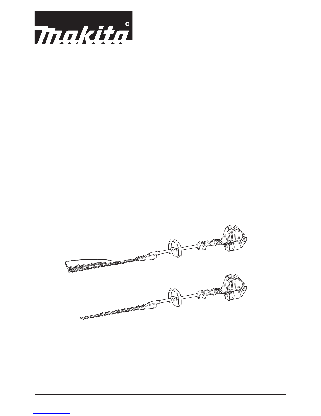
EN7350SH
EN5950SH
WARNING!
Read and understand this Manual. Always follow safety precautions in the Manual.
Improper use can cause serious injury!
AVERTISSEMENT !
Lisez et comprenez ce manuel. Suivez toujours les précautions de sécurité du Manuel.
Une utilisation inappropriée peut être à l’origine de blessures graves.
¡ADVERTENCIA!
Lea y comprenda este manual. Siga siempre las precauciones de seguridad descritas en el manual.
¡El uso incorrecto puede causar graves lesiones!
Owner’s and Safety Manual
for Pole Hedge Trimmer
Manuel d’emploi et de sécurité
du Taille-Haie Thermique Sur Perche
Manual de empleo y de seguridad
para el Cortasetos de Extensión a Gasolina
2
Thank you very much for choosing the MAKITA pole hedge trimmer.
We are pleased to offer you a product that is the result of an
extensive development program and many years of knowledge and
experience.
To safely obtain the best possible results from your MAKITA pole
hedge trimmer, please read this manual thoroughly before using the
machine, and follow all instructions given herein to assure proper
operation of the MAKITA pole hedge trimmer.
English
(Original instructions)
Table of Contents Page
Symbols ............................................................................................2
Safety instructions ............................................................................3
Technical data...................................................................................7
Designation of parts..........................................................................8
Connecting the trimmer unit to the pole............................................9
Fuel/refuelling ................................................................................. 10
Precautions before starting the engine ...........................................12
Operating the pole hedge trimmer ..................................................15
Maintenance ................................................................................... 16
Storage ........................................................................................... 21
Troubleshooting ..............................................................................22
Please note the following symbols when reading this instruction manual.
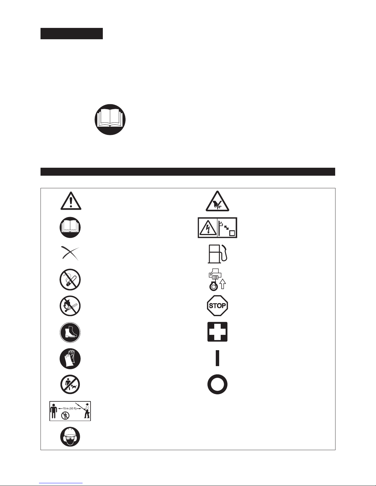
SYMBOLS
WARNING/DANGER Beware of pinching
Before usage, carefully read and fully
understand the instructions in this manual
Beware of electrical lines, risk of electrical
shock
PROHIBITION Fuel (Gasoline)
No smoking
Engine manual-start
No naked ame Emergency stop
Wear protective shoes First aid
Wear protective gloves ON/START
Keep working area clear of persons and
pets
OFF/STOP
Wear a protective helmet and eye and ear
protection
3
General Instructions
Before usage, carefully read this manual and thoroughly familiarize yourself with how to correctly handle the pole hedge trimmer. THIS EQUIPMENT CAN CAUSE
SERIOUS INJURY IF USED IMPROPERLY!
Always provide detailed instructions on how to correctly use the pole hedge trimmer when lending the equipment to another person. Make sure that the
instruction manual is handed over together with the pole hedge trimmer.
First-time users should ask their dealer for basic instructions on the correct handling of the pole hedge trimmer.
Store this manual in a location where it is easily accessible for quick reference. Do not allow persons under the age of 18 to operate the pole hedge trimmer. Individuals over 16 years old, however, may use the pole hedge trimmer for
training purposes if under the constant supervision of an adult familiar with the
operation of the pole hedge trimmer.
Always use the pole hedge trimmer with the utmost care and attention. Never attempt to modify the equipment. Follow the regulations about handling of pole hedge trimmers in your country. Serious injury may result if the pole hedge trimmer is used in the following circumstances. Do not use the pole hedge trimmer:
When feeling tired or ill.•
After consumption of alcohol and/or medication.•
At night or in poor lighting conditions.•
During pregnancy.•
Intended use
This pole hedge trimmer has been designed for the sole purpose of trimming hedges and bushes. Do not use the pole hedge trimmer for any other purposes.
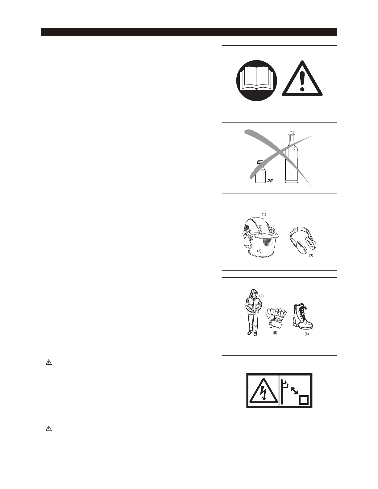
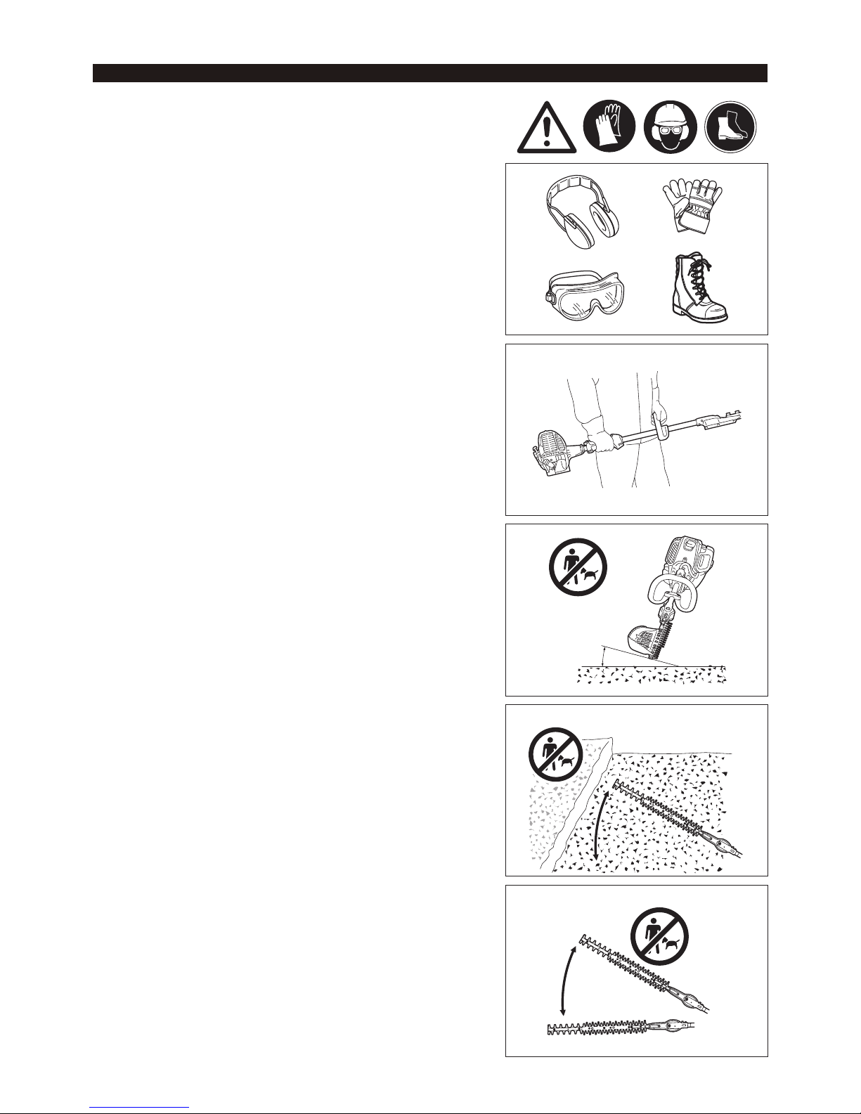
Personal protective equipment
Clothes worn should be functional and tight-tting without restricting movement. Do not wear clothing or jewelry that could get entangled in underbrush or in the
machine.
For adequate protection against injuries to head, eyes, feet, hands, as well as hearing impairment, the following protective equipment and clothing must be
used when working with the pole hedge trimmer.
To prevent injury to the head or the eyes, always wear a protective helmet (1) with goggles or a visor (2).
To avoid hearing impairment, wear adequate ear defenders (3) at all times. Use of a well-tting work overalls (4) is strongly recommended. Always wear rugged, leather working gloves (5) when operating the pole hedge trimmer.
When using the pole hedge trimmer, always wear sturdy shoes (6) with a non-slip sole. Special work shoes ensure good footing and protect against injury.
When touching blades or blade unit, wear protective gloves. Blades can cut bare hands severely.
Work area safety
-
DANGER: Keep the pole hedge trimmer away from electric lines and
communication cables. Touching or approaching high-voltage lines with pole
hedge trimmer can result in death or serious injury. Watch power lines and
electrical fences around the work area before starting operation.
Start and operate the engine only outdoors in a well ventilated area. Operation -
in a conned or poorly ventilated area can result in death due to suffocation or
carbon monoxide poisoning.
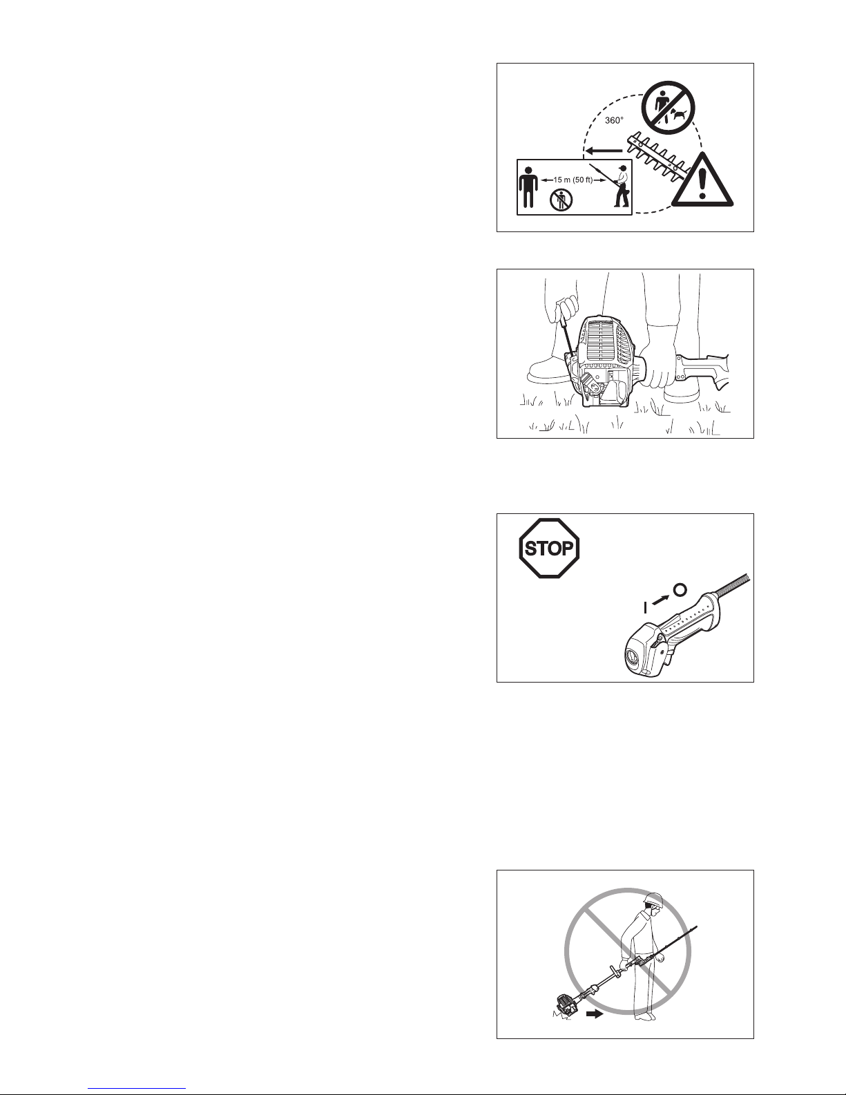
During operation, keep bystanders, in particular children, or animals at least 15 m away from the pole hedge trimmer. Stop the engine as soon as someone
approaches.
Before operation, examine the work area for wire fences, stones, or other solid objects. They can damage the blades.
-
WARNING: Use of this product can create dust containing chemicals which
may cause respiratory or other illnesses. Some examples of these chemicals
are compounds found in pesticides, insecticides, fertilizers and herbicides. Your
risk from these exposures varies, depending on how often you do this type of
work. To reduce your exposure to these chemicals: work in a well ventilated area,
and work with approved safety equipment, such as those dust masks that are
specially designed to lter out microscopic particles.
SAFETY INSTRUCTIONS
4
Starting the pole hedge trimmer
Before assembling or adjusting the equipment, switch off the engine and remove the spark plug cap.
Before starting the pole hedge trimmer, always make sure that the machine is in safe operational condition.
Never attempt to start the engine if the equipment is damaged. Check the operation of the throttle lever safety mechanism. The lock-off lever should have a smooth and easy action. Make sure that the lock-off lever functions
properly. Check that the handles are clean and dry and test the STOP switch to
ensure that it is functioning properly.
Always start the pole hedge trimmer in accordance with the directions provided in
this instruction manual.
Follow the instructions below to start the pole hedge trimmer
Start the pole hedge trimmer only after the machine has been completely assembled and all accessory parts have been attached.
When starting the engine, keep the blades clear of your body and other object, including the ground. The blades may move when starting and may cause serious
injury or damage to the blades and/or property.
Before starting the engine, make sure that cutter blades are not obstructed by any foreign objects such as stones, branches, etc.
Stop the engine immediately if engine problems occur. When pulling the starter knob, hold the equipment rmly against the ground by your left hand. Never step on the drive shaft.
If the blades move at idle, stop the engine and adjust the idle speed down. -
When operating the pole hedge trimmer, always maintain a rm grip on both handles. Wrap your ngers tightly around each handle, cradling the handle
between thumb and forenger. To keep the pole hedge trimmer under control at
all times, avoid changing your grip during operation. Make sure that the control
handles are in good condition and free of moisture, mud, oil or grease.
Always ensure secure and well-balanced footing
Always stop the engine immediately and discontinue operation if engine trouble occurs or if the machine starts making unusual noise.
Exhaust fumes are poisonous. Never operate the machine in an enclosed room or tunnel without ventilation (risk of suffocation and gas poisoning). Note that
carbon monoxide is an odorless gas. Always make sure that areas where the
engine is operated are adequately ventilated.
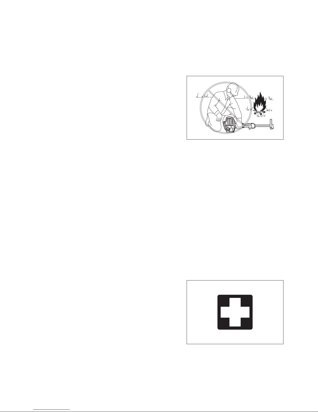
Stop the engine when resting, or when the pole hedge trimmer is left unattended. Place the machine in a safe location and make sure that no combustible material
is nearby.
Never place a hot pole hedge trimmer onto dry grass or combustible material. To reduce the risk of re, keep the engine and mufer free of debris, leaves or excessive lubricant.
Never operate the engine if the mufer is malfunctioning. Turn off the engine before transportation. Always stop the engine when: -
Resting•
Transporting the machine•
Cleaning the machine•
Refuelling the machine•
Performing maintenance on the machine•
Fixing a problem with the machine•
When carrying the equipment, carry it in a horizontal position by holding the shaft. -
Keep the hot mufer away from your body.
When transporting the machine in a vehicle, always securely attach the pole hedge trimmer to avoid leakage of residual fuel.
Always empty the fuel tank before transporting the pole hedge trimmer in a vehicle.
When unloading the machine from a vehicle, take extra care not to drop the pole hedge trimmer to the ground, as this may seriously damage the fuel tank.
Except in an emergency, never drop the pole hedge trimmer as this may seriously damage the machine.
When transporting the pole hedge trimmer, always lift the machine completely off of the ground. Never drag the engine across the ground as this may damage the
fuel tank and possibly cause a re.
Always use the cutter cover provided to protect and secure the cutting section of the pole hedge trimmer during transportation and storage.
If the equipment gets heavy impact or fall, check the condition before continuing work. Check the fuel system for fuel leakage and the controls and safety devices
for malfunction. If there is any damage or doubt, ask our authorized service
center for the inspection and repair.
Resting Transporting the machine Cleaning the machine Refuelling the machine Performing maintenance on -
the machine
Fixing a problem with the -
machine
5
Refuelling
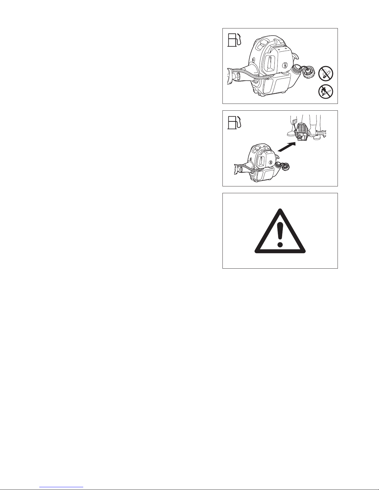
Before refuelling, stop the engine. Never refuel near naked ames. Do not smoke when refuelling. Always allow sufcient time for the engine to cool down before refuelling. Take care not to let your skin come into contact with petroleum products. Do not inhale gasoline fumes and always wear protective gloves when refuelling.
Change and clean protective wear at regular intervals.
Take extra care to avoid spilling gasoline and oil in order to avoid contamination of the ground (environmental protection). If gasoline or oil has been spilled onto
the pole hedge trimmer, immediately wipe the surface of the pole hedge trimmer
with a rag.
To avoid spontaneous combustion, allow wet rags to dry sufciently before
discarding them into an appropriate, covered container.
Make sure that no fuel comes in contact with your clothing. Change fuel- -
contaminated clothing immediately (re hazard).
Close the fuel tank and tighten the fuel tank cap securely. To restart the engine, transfer the pole hedge trimmer to a location at least 3 meters away from the
place of refuelling.
Check the fuel tank cap at regular intervals to make sure that the cap is securely fastened.
Never refuel the machine in an enclosed room. Fuel vapors accumulate at ground level (risk of explosion).
Store fuel in appropriate containers only, and make sure that stored fuel is out of the reach of children.
Operation
In the event of an emergency, turn off the engine immediately. If you feel any unusual condition (e.g. noise, vibration) during operation, switch off the engine. Do not use the pole hedge trimmer until the cause is recognized and
solved.
The blades continue to move for a short period after releasing the throttle trigger or switch off the engine. Don’t rush to contact the blades.
Never attempt to operate the equipment with one hand. Loss of control may result in serious or fatal injury. To reduce the risk of cut injuries, keep your hands and
feet away from the blades.
Keep your right hand under the shoulder height during operation. Otherwise you may lose control and result in injury.
During operation, never hit the blades against hard obstacles such stones and metals. Take particular care when cutting hedges next to or against wire fences.
When working close to the ground, make sure that no sand, grit or stones get
between the blades.
If the blades come into contact with stones or other solid objects, stop the engine immediately and check the blades for damage after removing the spark plug cap.
Replace the blades if damaged.
Never touch or approach the blades while they are moving. Blades can cut your -
nger easily. When handling or approaching the blade, stop the engine and
remove the spark plug cap.
If thick branches get jammed in the blades, immediately stop the engine, put the pole hedge trimmer down and then remove the obstruction after removing the
spark plug cap. Check the blades for damage before using the equipment again.
Accelerating the engine with the blades blocked increases the load and may damage the engine and/or clutch.
Check the cutting blades frequently during operation for cracks or blunt edges. Before the inspection, switch off the engine and wait until the blades stop
completely. Replace damaged or dull blades immediately, even if they have only
supercial cracks.
Do not touch the gear case. The gear case becomes hot during operation. Take a rest to prevent loss of control caused by fatigue. We recommend to take a 10 to 20-minute rest every hour.
Before cutting, pull the throttle lever fully to achieve the maximum speed. During operation, hold the pole hedge trimmer with both hands at all times. Only use the pole hedge trimmer in good light and visibility conditions. Beware of slippery and wet areas (ice and snow) during the cold season (danger of
slipping), and always ensure secure footing.
Never use the pole hedge trimmer while standing on an unstable surface or a steep slope.
Never use the pole hedge trimmer while standing on a ladder. Never climb a tree to use the pole hedge trimmer from the tree. To avoid stumbling or falling over objects, never walk backwards when working with the pole hedge trimmer.
Always stop the engine before cleaning or servicing the machine. Also, refrain from replacing parts before the engine has been stopped.
Do not operate the pole hedge trimmer if the cutting unit is damaged or worn. -
3 m
6
Maintenance work that can be performed by the user is limited to the activities
described in this instruction manual. Any other procedures are to be executed by an
authorized service agent.
Request MAKITA authorized service center to inspect and maintain the pole hedge
trimmer at regular interval.
Use only genuine spare parts and accessories supplied by MAKITA via authorized
service centers.
Use of unauthorized accessories and tools may increase the risk of accident and
injury. MAKITA accepts no liability whatsoever for accidents or damage resulting
from the use of unauthorized accessories and parts.
Storage
Before storing the equipment, perform full cleaning and maintenance. Fit the blade cover.
Empty the fuel tank before storage, and always store the pole hedge trimmer in a well-ventilated locked room. Make sure the pole hedge trimmer is out of children’s
reach at all times.
Do not prop the equipment against something, such as a wall. Otherwise the pole hedge trimmer may fall suddenly and cause an injury.
First aid
As a precaution for the occurrence of an accident, make sure that a fully stocked
rst aid kit is ready at hand.
Replace any items taken from the rst aid kit as soon as possible.
When asking for help in the case of an emergency, give the
following information:
Place of accident•
What happened•
Number of injured people•
Extent of injuries•
Your name•
Maintenance instructions
Have your equipment serviced by our authorized service center, always using only genuine replacement parts. Incorrect repair and poor maintenance can
shorten the life of the equipment and increase the risk of accidents.
Always do your utmost to keep pollution and noise emissions as low as possible when operating the pole hedge trimmer. Pay special attention to correct
adjustment of the carburetor.
Clean the pole hedge trimmer at regular intervals and periodically check whether all nuts and bolts are securely tightened.
Never service or store the pole hedge trimmer in the vicinity of naked ames, sparks, etc.
Never repair bent or broken blades by straightening or welding. It may cause parts of the blades to come off and result in serious injury. Contact MAKITA
authorized service center for MAKITA genuine blades to replace them.
To prevent further damage and/or personal injury, refrain from repairing a -
malfunctioning pole hedge trimmer if not qualied to do so. For repairs always
contact your dealer or an authorized service agent.
Do not attempt to modify or remodel the pole hedge trimmer as this may affect
operation safety.
Vibration
People with poor circulation who are exposed to excessive vibration may experience injury to blood vessels or the nervous system. Vibration may cause
the following symptoms to occur in the ngers, hands or wrists: “Falling asleep”
(numbness), tingling, pain, stabbing sensation, alteration of skin color or of the
skin. If any of these symptoms occur, see a physician!
To reduce the risk of “white nger disease”, keep your hands warm during operation and well maintain the equipment and accessories.

7
Model
EN5950SH EN7350SH
Loop handle
Dimensions (L x W x H)
70” x 9-1/2” x 9-1/2”
(1,780 mm x 242 mm x 241 mm)
75-1/4” x 10-1/4” x 9-1/2”
(1,910 mm x 259 mm x 241 mm)
Net weight 13.2 lbs (6.0 kg) 13.7 lbs (6.2 kg)
Volume (fuel tank) 36.6 cu.in (0.6 L)
Cutting length 23-1/4” (590 mm) 28-3/4” (730 mm)
Maximum branch diameter 9/32” (7 mm)
Engine displacement 1.5 cu.in (25.4 cm
3
)
Maximum engine performance 1.1 hp at 7,000/min (0.77 kW at 7,000 min
-1
)
Engine speed
at recommended max, spindle speed
10,000 RPM
Idling speed 3,000 RPM
Clutch engagement speed 4,400 RPM
Carburetor
(Diaphragm carburetor)
Diaphragm type
Ignition system Non-contact, magnet type
Spark plug type NGK CMR4A
Electrode gap 1/32” (0.7 - 0.8 mm)
Fuel Automobile gasoline (petrol)
Engine oil
API grade SF class or higher, SAE 10W-30 oil
(automobile 4-stroke engine oil)
Gear ratio 1/4.7
(For Canada) NOTE: This spark ignition system complies with the Canadian standard ICES-002.
TECHNICAL DATA
8
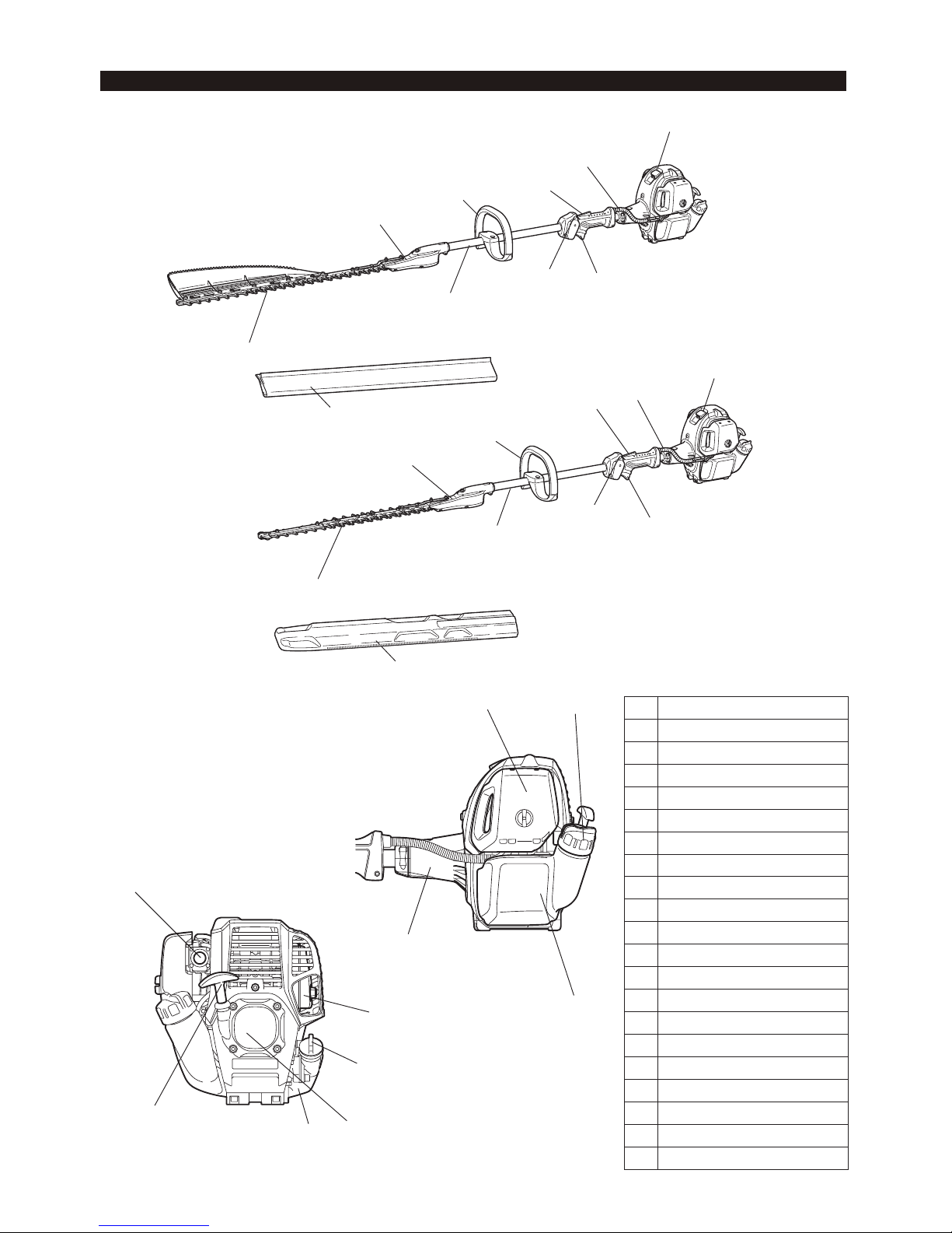
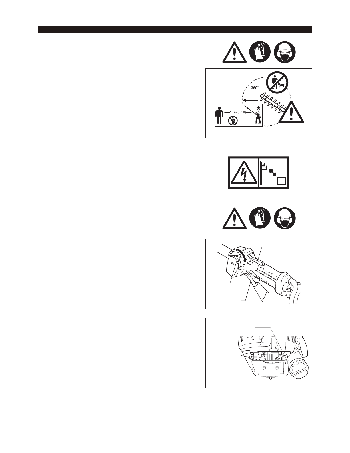
Designation of parts
1 Throttle cable
2 Lock-off lever
3 Throttle lever
4 Stop switch
5 Handle
6 Shaft
7 Gear box
8 Cutter blade
9 Air cleaner
10 Fuel tank cap
11 Fuel tank
12 Clutch case
13 Spark plug cap
14 Primer pump
15 Mufer
16 Recoil starter
17 Starter knob
18 Blade cover
19 Oil cap
20 Oil tank
DESIGNATION OF PARTS
9
10
11
12
14
15
19
20
16
17
18
1
1
2
2
3
3
4
4
EN7350SH
EN5950SH
5
5
6
6
7
7
8
8
13
13
18
9
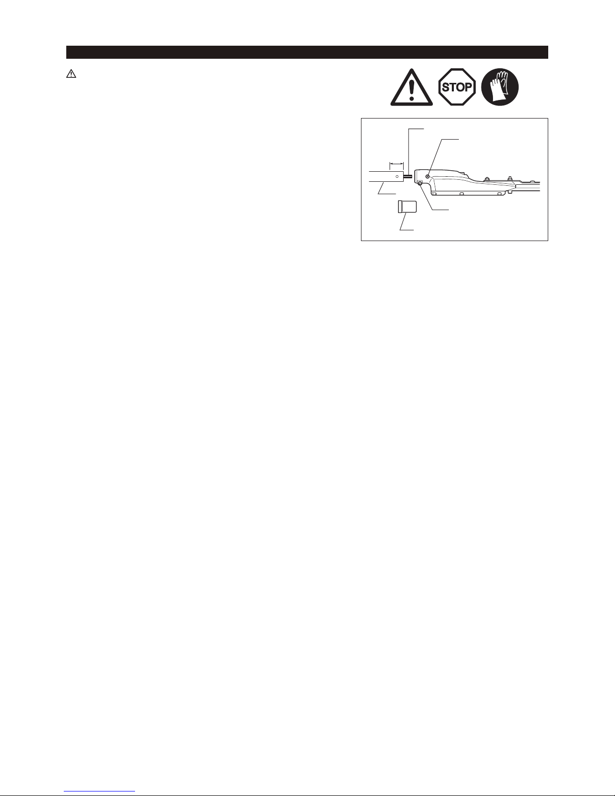
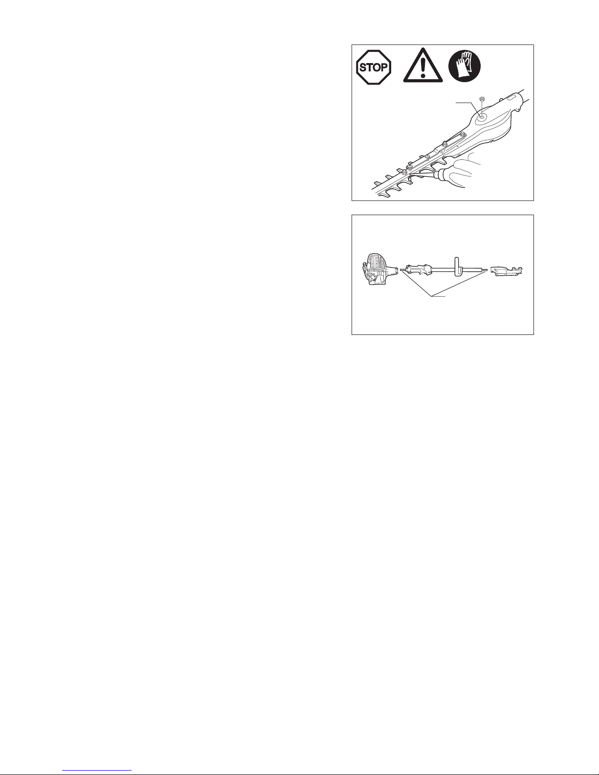
WARNING:
Make sure that the engine is turned off, and remove the spark plug cap before •
assembling the pole hedge trimmer.
Wear protective gloves!•
Secure cutting blades with the blade cover provided when connecting the trimmer •
unit to the pole.
1. Remove the cap from the shaft.
2. Loosen the M5 x 12 screw and M5 x 25 bolt.
3. Insert shaft into gear case.
NOTE: Make sure that the shaft is completely inserted into the gear case (approx.
44 mm/1.73”).
If you are having trouble inserting the shaft, manually rotate the drive axle a
little and try again.
4. Make sure that the shaft is properly inserted and then tighten the M5 x 12 screw
and the M5 x 25 bolt.
CONNECTING THE TRIMMER UNIT TO THE POLE
M5 x 25 bolt
Cap
Shaft
Drive axle
M5 x 12 screw
44 mm
10
BEFORE START OF OPERATION
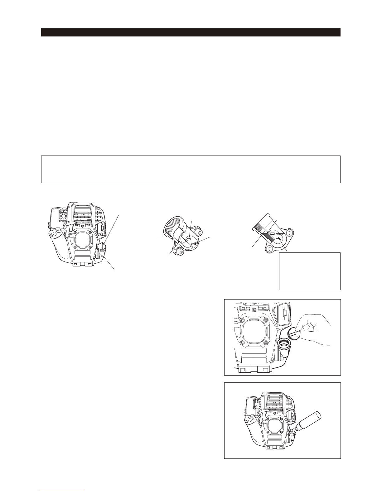
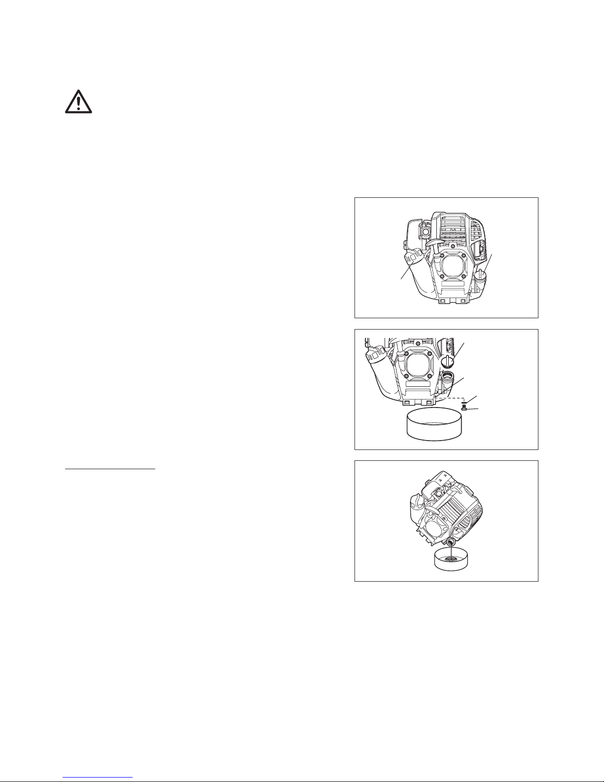
Inspection and rell of engine oil
Perform the following procedure, with the engine cooled down. Set the engine level, remove oil cap (Fig. 1), and check to see whether or not there is oil in the range between the upper limit and lower limit marks of the oil pipe (Fig. 2).
Top up with oil to upper limit mark if oil is insufcient (oil level is close to lower limit mark) (Fig. 3). The area surrounding the external marks is transparent, so the amount of oil inside can be checked without having to remove the oil cap. However, if oil pipe becomes extremely dirty, visibility may be lost, and oil level will have to be checked against stepped section on inside of
oil pipe.
For reference, the oil rell time is about 10 h (every 10 refuelling). If the oil changes in color or mixes with dirt, replace it with new one. (For the interval and method of replacement, refer to P18)
Recommended oil: SAE 10W-30 oil of API Classication, Class SF or higher (4-stroke engine for automobile)
Oil volume: Approx. 0.08 L
NOTE: If the engine is not kept upright, oil may go into around the engine, and may be relled excessively.
If the oil is lled above the limit, the oil may be contaminated or may catch re with white smoke.
Point 1 in Replacement of oil: “Oil cap”
Remove dust or dirt near the oil rell port, and detach the oil cap. Keep the detached oil cap free of sand or dust. Otherwise, any sand or dust adhering to the oil cap may cause irregular oil circulation or wear on the engine parts, which will result in troubles.
(2) Fill with oil to upper limit mark. (see Fig. 3)
Use oil bottle when lling.
(3) Securely tighten the oil cap. Insufcient tightening may cause oil leakage.
Oil cap
Oil pipe
Fig. 1 Fig. 2 Oil pipe Fig. 3
Internal stepped
section (upper limit)
External mark
(upper limit)
External mark
(lower limit)
Internal stepped
section (lower limit)
Top up with oil
until oil level
reaches internal
stepped section
(upper limit).
The area between the
external upper and lower
limits is transparent, so
oil level can be checked
extternally against these
marks.
(1) Keep the engine level, and detach the oil cap.
FUEL/REFUELLING
11
Note
Do not replace oil with the engine in a tilted position.•
Filling with oil while engine is tilted leads to overlling which causes oil contamination and/or white smoke.•
Point 2 in Replacement of oil: “If oil spills out”
If oil spills out between the fuel tank and engine main unit, the oil is sucked into through the cooling air intake port, which will contaminate the engine. Be sure to wipe out spilled oil before start of operation.
REFUELLING
Handling of fuel
It is necessary to handle fuel with utmost care. Fuel may contain substances similar to solvents. Refuelling must be performed in a sufciently
ventilated room or in the open air. Never inhale fuel vapors, and keep fuel away from you. If you touch fuel repeatedly or for a long time, the
skin becomes dry, which may cause skin disease or allergy. If fuel comes into the eye, clean the eye with fresh water. If your eye remains still
irritated, consult your doctor.
Storage period of fuel
Fuel should be used within a period of 4 weeks, even if it is kept in a special container in a well-ventilated and shaded area.
Otherwise, fuel may deteriorate in one day.
STORAGE OF MACHINE AND REFILL TANK
Keep the machine and tank at a cool place free from direct sunshine. Never keep the fuel in a car. -
Fuel
The engine is a four-stroke engine. Be sure to use an unleaded automobile gasoline 87 or higher octane ((R+M)/2). It may contain no more than
10% alcohol (E-10).
Points for fuel
Never use a gasoline mixture which contains engine oil. Otherwise, it will cause excessive carbon accumulation or mechanical troubles. Use of deteriorated oil will cause irregular start-up. -
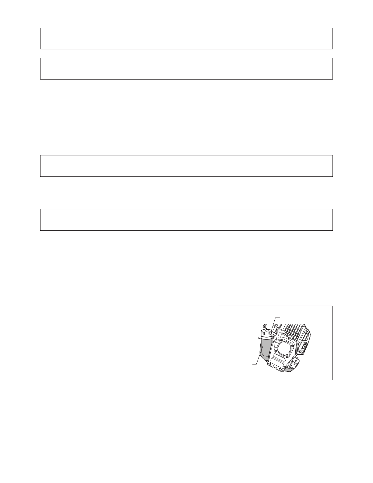
Refuelling
WARNING: INFLAMMABLES STRICTLY PROHIBITED
Loosen the tank cap a little to release the tank pressure. Detach the tank cap, and refuel, discharging air by tilting the fuel tank so that the refuel port will be oriented upward. (DO NOT ll fuel up to the top of the tank.)
Wipe well the periphery of the tank cap to prevent foreign matter from entering the fuel tank. After refuelling, securely tighten the tank cap. -
If there is any aw or damage on the tank cap, replace it.•
The tank cap wears out in course of time. Replace it every two to three years.•
Fuel tank
Fuel upper
limit
Fuel tank cap
12
At all times allow a 15-meter diameter safety zone around the working area. Make sure that all persons (in particular children) and/or animals remain outside
this zone.
Before using the pole hedge trimmer, make sure that the machine is in safe operational condition. Make sure that the cutting blades are not damaged, and
check the throttle lever for easy action. Make sure that the cutting blades are
not in motion when the engine is idling. If the machine is not operating normally,
contact your dealer to have the machine adjusted. Make sure that the handles
are clean and dry, and test whether the I-O switch is functioning properly. Start
the engine only in accordance with the instructions given in this manual. Do not
use any other methods to start the pole hedge trimmer.
Start the engine of the pole hedge trimmer only after having read and fully understood the instructions. Never attempt to start a pole hedge trimmer that has
not been fully assembled. Serious injury may result otherwise.
Before starting the engine, always make sure that the cutting blades are not obstructed by stones, branches or any other solid objects.
Check the working area for wires, cord, glass or other foreign objects that could get caught in the cutting blades.
Electrical shock: Be aware of all electrical lines in the vicinity. Check the entire work area for the presence of power lines and electrical fences before starting to
work.
POINTS IN OPERATION AND HOW TO STOP
Observe the applicable accident prevention regulations!
STARTING
Move at least 3 m away from the place of refuelling. Put the pole hedge trimmer on
a clean piece of ground taking care that the cutting blades do not come into contact
with the ground or any other objects.
A: Cold start
1) Set this machine on a at space.
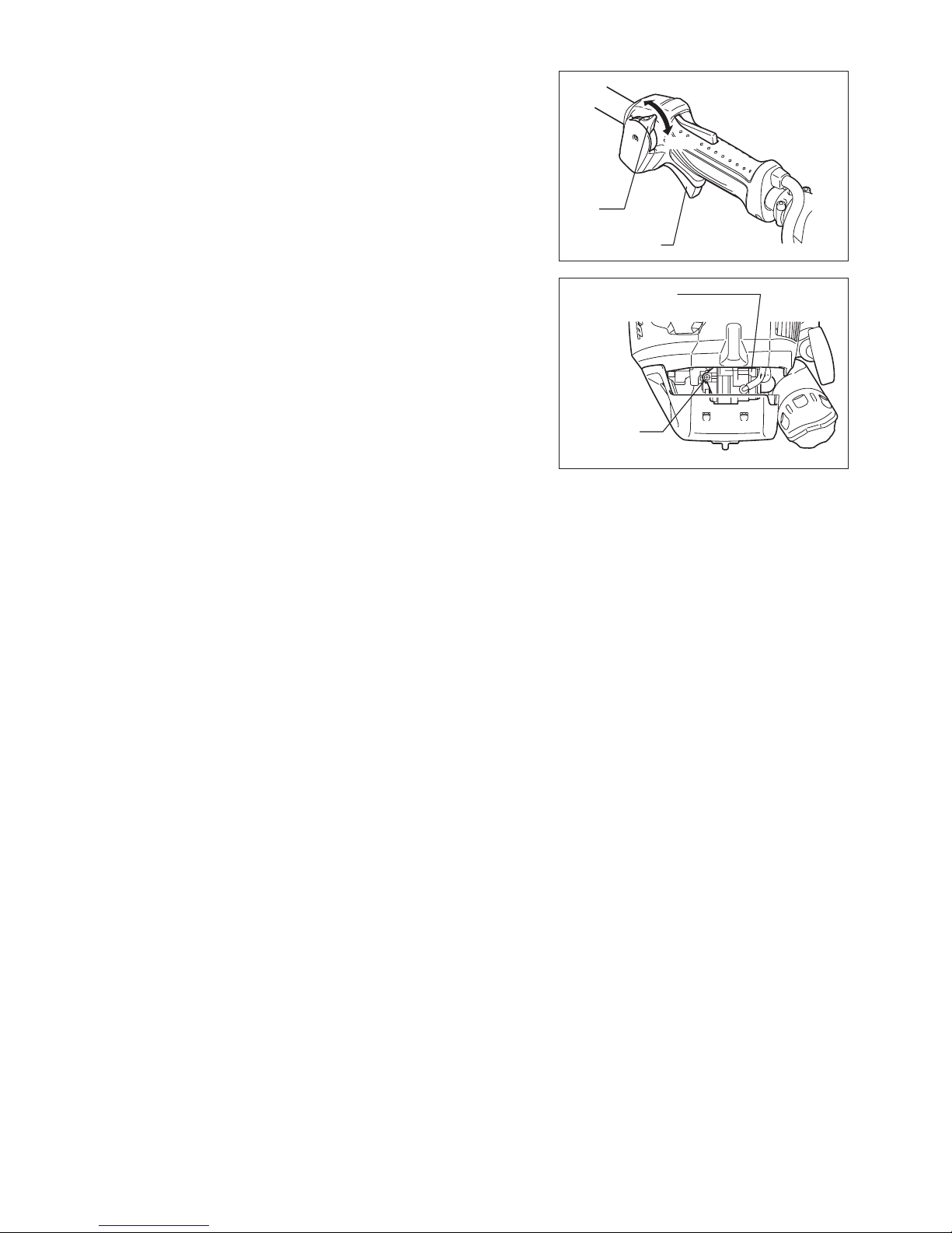
2) Set the I-O switch (1) to OPERATION.
3) Primer pump
Continue to push the primer pump until the fuel comes into the primer pump. (In
general, fuel comes into the primer pump by 7 to 10 pushes.) If the primer pump
is pushed excessively, an excess of gasoline returns to the fuel tank.
OPERATION
Lock-off lever
Low speed
High
speed
(1)
STOP
Throttle lever
Primer pump
Carburetor
PRECAUTIONS BEFORE STARTING THE ENGINE
13
4) Recoil starter
Pull the start knob gently until it is hard to pull (compression point). Then, return
the start knob, and pull it strongly. Never pull the rope to the full extension. Once
the start knob is pulled, never release your hand immediately. Hold the start
knob until it returns to its original point.
5) Warm-up operation
Continue warm-up operation for 2 to 3 minutes.
NOTE: In case of excessive fuel intake, remove the spark plug and pull the starter
handle slowly to remove excess fuel. Also, dry the electrode section of the
spark plug.
Caution during operation:
If the throttle lever is opened fully in a no-load operation, the engine speed is
increased to 10,000 min
-1
(rpm) or more. Never operate the engine at a higher
speed than required and at an approximate speed of 6,000 - 9,000 min
-1
(rpm).
B: Startup after warm-up operation
1) Repeat pushing the primer pump gently.
2) Keep the throttle lever at the idling position.
3) Pull the recoil starter strongly.
4) If it is difcult to start the engine, open the throttle by about 1/3.
Pay attention to the cutting blades which may move.
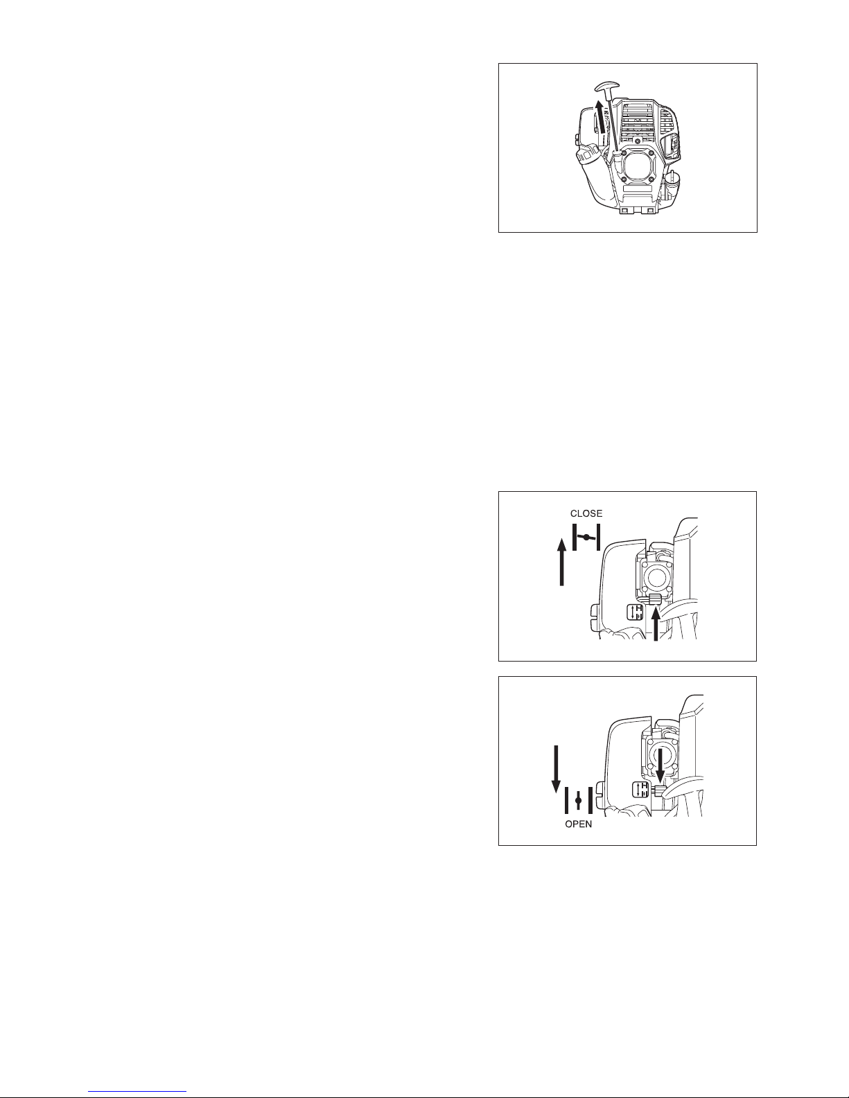
At times, such as winter, when starting the engine is difcult, operate choke
lever with the following procedure when starting engine.
After implementing startup steps 1) to 3), set choke lever to the CLOSE position.•
Implement startup step 4) and start engine.•
Once engine starts, set choke lever to the OPEN position.•
Implement startup step 5) and complete warm up.•
CAUTION: If a bang (explosive sound) is heard and the engine stops, or the
just-started engine stalls before the choke lever is operated, return the
choke lever to the OPEN position, and pull the starter knob a few times
again to start the engine.
CAUTION: If the choke lever is left in the CLOSE position, and the starter knob
merely pulled repeatedly, to much fuel will be sucked in, and the engine
will become difcult to start.
14
STOPPING
1) Release the throttle lever (2) fully, and when the engine speed has lowered, set
the I-O switch to STOP the engine will now stop.
2) Be aware that the cutting head may not stop immediately and allow it to slow
down fully.
ADJUSTMENT OF LOW-SPEED ROTATION (IDLING)
When it is necessary to adjust the low-speed rotation (idling), perform it by the
carburetor adjusting screw.
CHECKUP OF LOW-SPEED ROTATION
Set the low-speed rotation to 3,000 rpm (/min). If it is necessary to change the rotation speed, regulate the adjusting screw
(illustrated on the right), with Phillips screwdriver.
Turn the adjusting screw to the right, and the engine speed will increase. Turn the adjusting screw to the left, and the engine speed will drop.
The carburetor is generally adjusted before shipment. If it is necessary to readjust it, please contact Authorized Service Agent.
Carburetor
Adjusting
screw
STOP
(1)
(2)
15
15 m
(50 ft)
15° - 30°
15 m
(50 ft)
15 m
(50 ft)
Do not touch the cutting blade portion of the pole hedge trimmer during operation, or when the engine is running.
Take extra care not to inhale exhaust gases when working with the pole hedge trimmer. Never operate the pole hedge trimmer in an enclosed room or an area
with insufcient ventilation (risk of suffocation and gas poisoning). Note that
carbon monoxide is an odorless gas that is, it cannot be detected by the sense of
smell.
Always wear adequate protective wear before starting to work with the pole hedge trimmer.
Stop the engine immediately if the mufer is not functioning properly. Only use the pole hedge trimmer in good light and visibility conditions. Do not operate the pole hedge trimmer in darkness or fog. Beware of slippery and wet areas (ice and snow) during the cold season (danger of slipping), and always
ensure secure footing.
Never use the pole hedge trimmer while standing on an unstable surface or a steep slope.
Never use the pole hedge trimmer while standing on a ladder. Never climb a tree to use the pole hedge trimmer from the tree. Continuously check the working area for wires, cord, glass or other foreign objects that could get caught in the cutting blades.
Make sure that the cutting blades are in rapid motion before starting to cut. Always grip the pole hedge trimmer with both hands and maintain a rm grip when working with the machine.
To assure optimal control over the pole hedge trimmer, always completely wrap your hands around the handles (use your thumb for counter pressure) and apply
a rm grip on the handles.
Note that the cutting blades will remain in motion for up to two seconds after the throttle lever has been released.
Do not cut with the pole hedge trimmer at low engine speed. The speed of the cutting blades cannot be adjusted properly with the throttle lever when the engine is running at low speed.
To trim the top surface of a hedge, rst align the cutting blades at an angle of 15° - 30° in the cutting direction and keep the pole hedge trimmer in a horizontal
position. Then start trimming the hedge using a circular movement, much like
drawing circle segments with the hedge trimmer shaft.
To trim the sides of a hedge, align the blades parallel to the surface to be cut and start trimming with semi-circular upward (down-up) movements.
Pay attention when trimming a hedge close to or against wire fences. Do not touch hard objects such as wire fence, stone or ground with the cutting blades. It may cause blades to crack, chip or break.
Do not use the pole hedge trimmer over an extended period of time. As a general rule, for every 50 minutes of operation take a 10-20 minutes rest.
If the cutting blades come into contact with stones or other solid objects, stop the engine immediately and check the blades for damage. Replace the blades if
damaged.
If the pole hedge trimmer develops a problem during operation (strange noises, vibration, etc.), immediately stop the engine. Do not use the machine again until
the problem has been recognized and solved.
Always do your utmost to keep pollution and noise emissions as low as possible when operating the pole hedge trimmer. Pay special attention to correct
carburetor adjustment.
If thick branches get jammed in the cutting blades, immediately stop the engine, lay the equipment on the ground and remove the obstruction. Check the blades
for damage before using the machine again.
Chip receiver (only for EN7350SH)
This model equips chip receiver. It helps avoiding cut off leaves being thrown away.
OPERATING THE POLE HEDGE TRIMMER
16
Before performing any maintenance work on the pole hedge trimmer (blade cleaning, etc.), always stop the engine and wait until the engine has cooled down.
As an additional safety precaution, also remove the spark plug cap.
Do not try to straighten or weld bent or broken cutting blades. Always replace damaged blades.
Stop the engine at regular intervals to check the cutting blades for possible damage (perform a tapping-resonance test to detect hard-to-see hairline cracks).
Always make sure that the teeth of the blades are sharp.
Clean the pole hedge trimmer regularly. During cleaning also check all screws, nuts and bolts are well tightened.
To reduce the risk of re, never service or store the pole hedge trimmer in the vicinity of open res.
Always wear rugged protective gloves when handling the cutting blades. Contact your dealer for replacement cutting blades. Never use gasoline, benzine, thinner, alcohol or the like for cleaning. Discoloration, deformation or cracks may result.
Sharpening the blade
If the cutting blades have become blunt and cutting performance is poor, have the
blades sharpened by an authorized service agent.
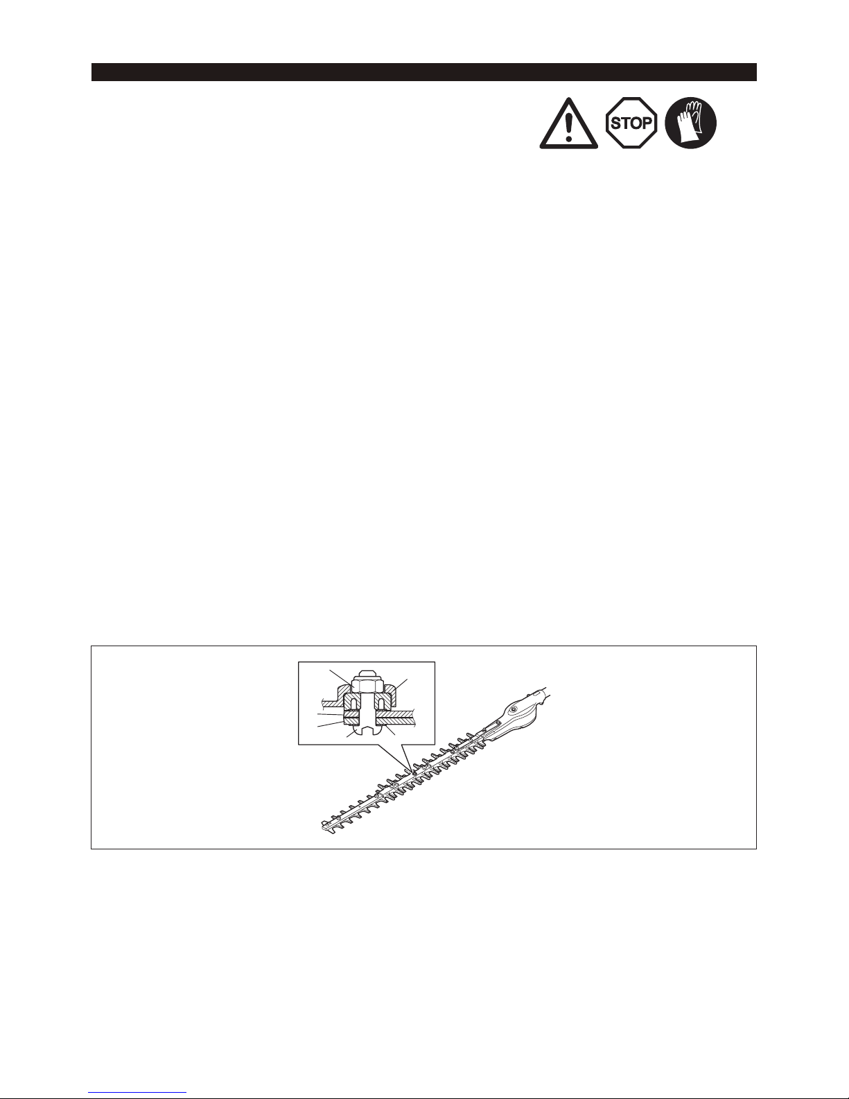
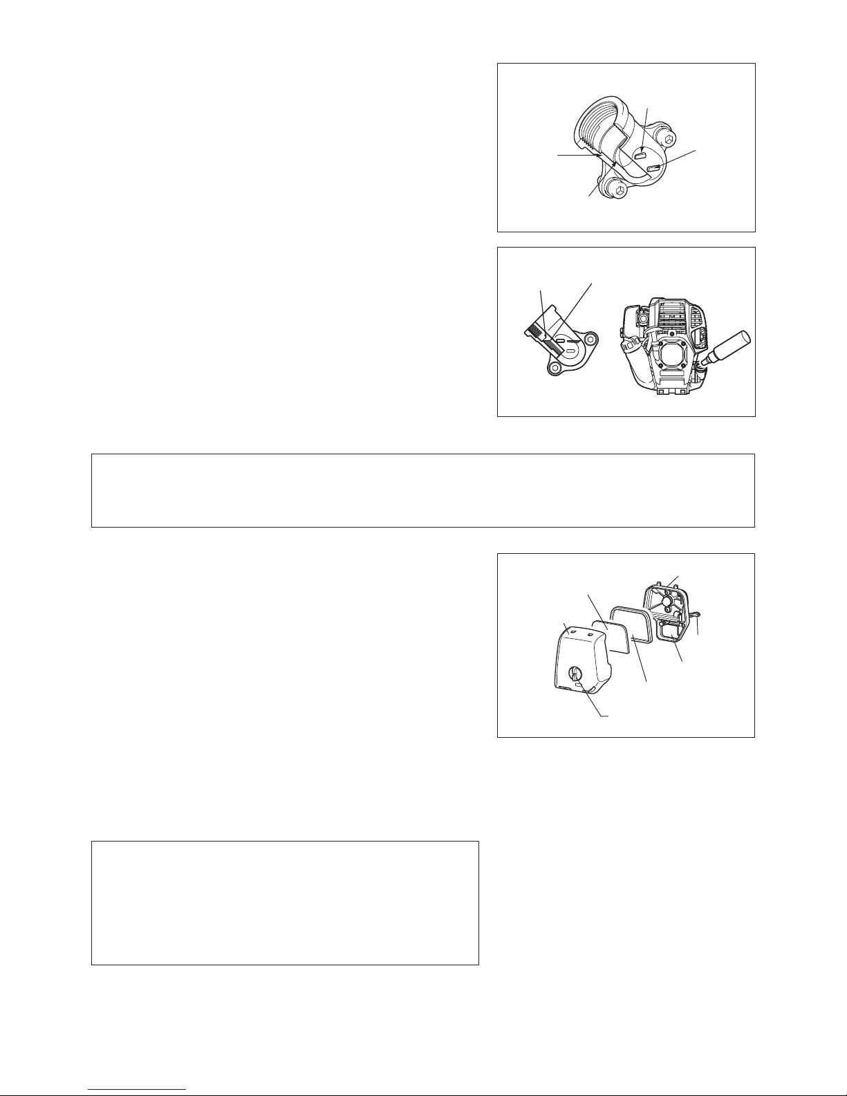
Adjusting blade clearance
The upper/lower blades wear. If you cannot get a clean cut though the blades are sharp enough, adjust the clearance as follows.
The tightness of the truss bolt decides the clearance of the blades. The nut holds the truss bolt with certain tightness. Too loose clearance
causes blunt cut, but too tight clearance causes unnecessary heat and sooner worn-out of the blades.
1. Loosen the nut (1) with a box or open-ended wrench.
2. Tighten the truss bolt (2) with a hex wrench lightly till it stops. And then, screw it back between a quarter turn and a half turn to gain
necessary clearance.
3. Tighten the nut (1), holding the truss bolt (2).
4. Apply light oil on the friction surface of the blades.
5. Start the engine, operate the throttle on and off for a minute.
6. Stop the engine and touch the surface. If they are not too hot to touch, you have made a proper adjustment. If they are too hot to touch, turn
the truss bolt (2) back a little and repeat the step 5 to 6.
NOTE: Before making the adjustment, stop the engine and wait for the blades to stop.
The blades have a slot around the truss bolt (2). In case you nd dust in the end of any of the slots, clean it.
1
2
3
4
5
6
1 Hexagonal U-nut
2 Truss bolt
3 Flat washer
4 Blade guide
5 Upper blade
6 Lower blade
MAINTENANCE
17
Adding grease and lubricant
Important: Make sure that the surface of gear box is completely cold before
lubricating.
The gearbox of the pole hedge trimmer should be greased every 25 working hours. The grease hole locates under the bolt. Remove the bolt to lubricate. Add
approx. 5 g (7 cc) of grease to the grease hole. Return the bolt after lubrication.
(Some grease will emerge from the head of the gearbox (located at the base
of the blades) when the pole hedge trimmer is set in motion the rst time after
greasing. Use this as a rough indication for the amount of grease to be supplied.)
CAUTION: Observe greasing intervals and the amount of grease to be supplied.
Mechanical parts of the pole hedge trimmer may be damaged if grease
is not supplied at the prescribed intervals or if an insufcient amount of
grease is added.
In case you remove the shaft from the engine or gear case, perform the following
steps when reassembling:
1. Remove foreign objects from the drive axle.
2. Lubricate grease to the drive axle.
Daily inspection and maintenance
To ensure a long service life of your pole hedge trimmer, perform the following
inspections and maintenance on a daily basis.
Before use; -
Always check for loose or missing parts before starting operation. Pay special •
attention to the cutting unit and make sure that the cutting blade lock screws
are well tightened.
Check for clogging of the cooling air passages and the cooling ns of the •
cylinder before starting operation. Clean if necessary.
After use; -
Clean the pole hedge trimmer externally and inspect for damage.•
Clean the air lter. Clean the lter several times a day if working in extremely •
dusty conditions.
Check the cutting blades for damage. Make sure that the blades are securely •
mounted.
If the cutting blades still continue to run at idle after the adjustment, consult •
your nearest authorized service agent.
Grease hole
Drive axle
18
In replacement, perform the following procedure.
1) Make sure that the fuel tank cap is tightened securely.
2) Put large container (pan, etc.) under drain hole.
3) Remove drain bolt and then remove oil cap to drain out oil from drain hole. At
this time, be sure not to mislay drain bolt’s gasket, or to dirty any of the removed
components.
4) Once all the oil has been drained, combine gasket and drain bolt, and tightly
secure drain bolt, so that it will not loosen and cause leaks.
* Use cloth to fully wipe off any oil attached to bolt and equipment.
Alternative draining method
Remove oil cap, tilt pole hedge trimmer toward oil ller hole, and drain out oil.
Collect oil in container.
REPLACEMENT OF ENGINE OIL
Deteriorated engine oil will shorten the life of the sliding and rotating parts to a great extent. Be sure to check the period and quantity of
replacement.
DANGER: In general, the engine main unit and engine oil still remain hot just after the engine is stopped. In replacement of oil, make
sure that the engine main unit and engine oil are sufciently cooled down. Otherwise, there may remain a risk of scald.
Allow sufcient time after stopping engine for the engine oil to return to the oil tank to ensure accurate reading of the oil
level indicator.
NOTE: If the oil lled above the limit, it may become dirty or may catch re with white smoke.
Interval of replacement: After rst 20 operating hours, followed by every 50 operating hours
Recommended oil: SAE10W-30 oil of API Classication SF Class or higher (4-stroke engine oil for automobile)
Fuel tank cap
Oil cap
Oil cap
Drain hole
Gasket
Drain bolt
19
5) Set the engine level, and gradually ll up to upper limit mark with new oil.
6) After lling, tightly secure oil cap, so that it will not loosen and cause leaks. If oil
cap is not tightly secured, it may leak.
External mark
(upper limit)
Internal
stepped
section
(upper limit)
Internal stepped
section (lower limit)
External
mark
(lower
limit)
Upper limit
mark
Oil
POINTS ON OIL
Never discard replaced engine oil in garbage, earth or sewage ditch. Disposal of oil is regulated by law. In disposal, always follow the relevant laws and regulations. For any points remaining unknown, contact Authorized Service Agent.
Oil will deteriorate even when it is kept unused. Perform inspection and replacement at regular intervals (replace with new oil every 6 months).
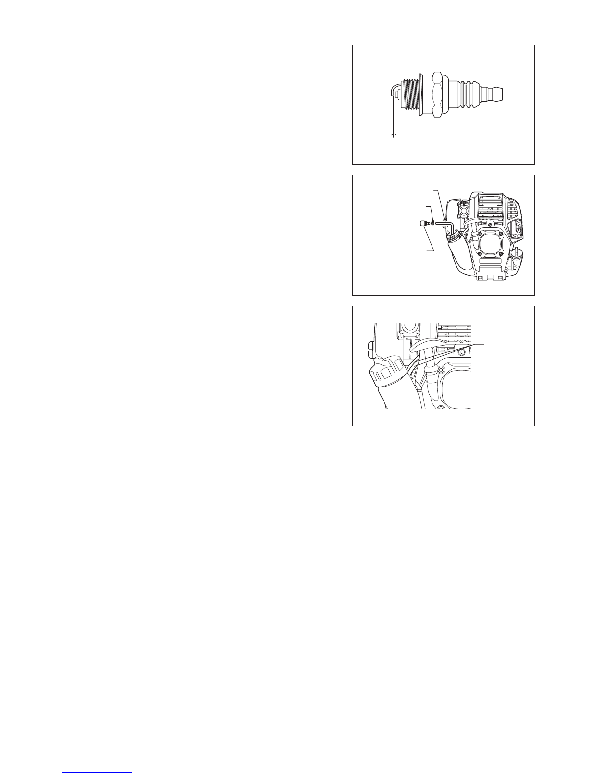
Cleaning the air cleaner
DANGER: Inammables strictly prohibited
Check and clean the air cleaner daily or every 10 operating hours.
Turn the choke lever fully to the close side, and keep the carburetor free from dust or dirt.
Loosen the xing bolt. Remove the air cleaner cover by pulling its bottom side. Remove the elements and tap them to remove dirt. If the elements are heavily contaminated: Remove the elements, immerse them in warm water or in water-diluted neutral
detergent, and dry them completely. Do not squeeze or rub them when washing.
Before attaching the elements, be sure to dry them completely. Insufcient drying of the elements may lead to difcult startup.
Wipe out oil adhering around the air cleaner cover and the breather part with waste cloth.
Fit the element (sponge) into the element (felt). Fit the elements into the plate so that the sponge faces the air cleaner cover.
Immediately attach the cleaner cover and tighten it with xing bolts. (In remounting, rst place the upper claw, and then the lower claw.)
NOTICE:
Clean the elements several times a day, if excessive dust adheres to it. Dirty -
elements reduce engine power and make starting engine difcult.
Remove oil on the elements. If operation continues with the elements remaining not cleared of oil, oil in the air cleaner may fall outside, resulting in
contamination of the environment.
Do not put the elements on the ground or dirty place. Otherwise they pick up dirt or debris and it may damage the engine.
Never use fuel for cleaning the elements. Fuel may damage them. -
Air cleaner
cover
Element
(sponge)
Plate
Choke lever
Breather part
Element (felt)
Fixing bolt
20
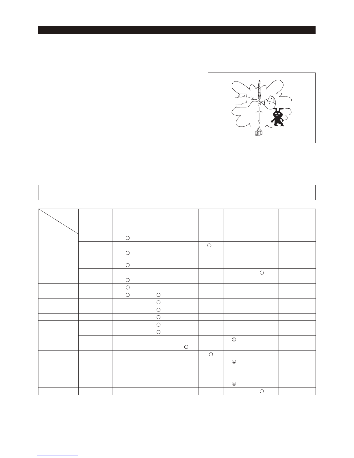
CHECKING THE SPARK PLUG
Only use the supplied universal wrench to remove or to install the spark plug. The gap between the two electrodes of the spark plug should be 0.7 - 0.8 mm -
(0.028” - 0.032”). If the gap is too wide or too narrow, adjust it. If the spark plug is
clogged or contaminated, clean it thoroughly or replace it.
CAUTION: Never touch the spark plug connector while the engine is running
(danger of high voltage electric shock).
Cleaning the fuel lter (suction head in the fuel tank)
WARNING: INFLAMMABLES STRICTLY PROHIBITED
Check and clean the fuel lter monthly or every 50 operating hours.
Check the fuel lter periodically. To check the fuel lter, follow the steps below.
(1) Remove the fuel tank cap, drain the fuel to empty the tank. Check the tank
inside for any foreign materials. If any, remove them.
(2) Pull out the suction head by using a wire hook through the tank opening.
(3) If the fuel lter clogged slightly, clean it. To clean it, gently shake and tap it in
fuel. To avoid damage, do not squeeze or rub it. The fuel used for the cleaning
must be disposed in accordance with the method specied by regulations in
your country.
If the fuel lter became hard or heavily clogged up, replace it.
(4) After checking, cleaning or replacing, push the fuel lter in all the way to the
bottom of the fuel tank.
Clogged or damaged fuel lter can cause insufcient fuel supply and reduce engine
power. Replace the fuel lter at least quarterly to ensure satisfactory fuel supply to
the carburetor.
0.7 mm - 0.8 mm
(0.028” - 0.032”)
Fuel pipe
Hose clamp
Fuel lter
Replacing the fuel pipe
CAUTION: Inammables strictly prohibited
Check and clean the fuel pipe daily or every 10 operating hours.
Replace the fuel pipe every 200 operating hours or every year regardless of
operating frequency. Otherwise fuel leakage may lead to re.
If you nd any leakage during inspection, replace the fuel pipe immediately.
INSPECTION OF BOLTS, NUTS AND SCREWS
Retighten loose bolts, nuts, etc. Check for fuel and oil leakage. Replace damaged parts with new ones for safety operation. -
CLEANING OF PARTS
Keep engine clean by wiping down with a cloth rag. Keep the cylinder ns free of dust or dirt. Dust or dirt adhering to the ns will cause piston seizure.
REPLACEMENT OF GASKETS AND PACKINGS
Replace gaskets and packings if the engine is disassembled.
For any maintenance or adjustment not described in this manual, ask your local
MAKITA authorized service center.
Fuel pipe
21
Drain fuel from the fuel tank and carburetor according to the following procedure: -
1) Remove the fuel tank cap, and drain fuel completely.
If there is any foreign materials remaining in the fuel tank, remove it completely.
2) Pull out the fuel lter from the rell port using a wire.
3) Push the primer pump until fuel is drained from there, and drain fuel coming into
the fuel tank.
4) Reset the lter to the fuel tank, and securely tighten the fuel tank cap.
5) Then, continue to operate the engine until it stops.
Remove the spark plug, and drip several drops of engine oil through the spark plug hole.
Gently pull the starter handle so that engine oil will spread over the engine, and attach the spark plug.
Attach the cover to the cutting blades. During storage, keep the rod horizontal or keep the machine upright with the blade edge oriented upward. (In this case, pay full attention to prevent the
machine from falling.)
Never store the machine with the cutting blade edge oriented downward. Lubricating oil may spill out.
Keep the drained fuel in a special container in a well-ventilated shade. -
WARNING: When draining the fuel, stop the engine and wait for the engine to cool down.
Failure to do so may cause burns or re.
ATTENTION: When you store the machine for a long time, drain all fuel from the fuel tank and carburetor, and keep it at a dry and
clean place.
STORAGE
Drain fuel
Humidity
Attention after long-time storage
Before startup after long-time shutdown, be sure to replace oil (refer to P18). Oil will deteriorate while the machine is kept out of operation. -
Operating
time
Item
Before
operation
Daily
(10h)
25h 50h 200h
Shutdown/
rest
Corresponding
P
Engine oil Inspect/clean
10
Replace
*
1
18
Tightening parts
(bolt, nut)
Inspect
20
Fuel tank Clean/inspect
-
Drain fuel
*
3
21
Throttle lever Check function
12
Stop switch Check function
12, 14
Cutting blades Inspect
12, 16
Low-speed rotation Inspect/adjust
14
Air cleaner Clean
19
Ignition plug Inspect
20
Cooling air duct Clean/inspect
20
Fuel pipe Inspect
20
Replace
*
2
-
Gear-case grease Rell
17
Fuel lter Clean/replace
20
Clearance between
air intake valve
and air discharge
valve
Adjust
*
2
-
Engine overhaul
*
2
-
Carburetor Drain fuel
*
3
21
*1 Perform initial replacement after 20h operation.
*2 For the 200 operating hour inspection, request Authorized Service Agent or a machine shop.
*3 After emptying the fuel tank, continue to run the engine and drain fuel in the carburetor.

22
Before making a request for repairs, check a trouble for yourself. If any abnormality is found, control your machine according to the description
of this manual. Never tamper or dismount any part contrary to the description. For repairs, contact Authorized Service Agent or local dealership.
State of abnormality Probable cause (malfunction) Remedy
Engine does not start
Failure to operate primer pump Push 7 to 10 times
Low pulling speed of starter rope Pull strongly
Lack of fuel Feed fuel
Clogged fuel lter Clean
Broken fuel tube Straighten fuel tube
Deteriorated fuel Deteriorated fuel makes starting more difcult.
Replace with new one. (Recommended
replacement: 1 month)
Excessive suction of fuel Set throttle lever from medium speed to high
speed, and pull starter handle until engine
starts. Once engine starts, cutting blades
start moving. Pay full attention to cutting
blades.
If engine will not start still, remove spark plug,
make electrode dry, and reassemble them as
they originally are. Then, start as specied.
Detached plug cap Attach securely
Contaminated spark plug Clean
Abnormal clearance of spark plug Adjust clearance
Other abnormality of spark plug Replace
Abnormal carburetor Make request for inspection and maintenance.
Starter rope cannot be pulled Make request for inspection and maintenance.
Abnormal drive system Make request for inspection and maintenance.
Engine stops soon
Engine speed does not increase
Insufcient warm-up Perform warm-up operation
Choke lever is set to “
” although engine is
warmed up.
Set to “ ”
Clogged fuel lter Clean or replace
Contaminated or clogged air cleaner Clean
Abnormal carburetor Make request for inspection and maintenance.
Abnormal drive system Make request for inspection and maintenance.
Cutting blade does not move
Stop engine immediately
Loosened cutting blades-tightening nut Tighten securely
Twigs caught by cutting blades. Remove foreign matter
Abnormal drive system Make request for inspection and maintenance.
Main unit vibrates abnormally
Stop engine immediately
Broken, bent or worn cutting blades Replace cutting blades
Loosened cutting blades-tightening nut Tighten securely
Abnormal drive system Make request for inspection and maintenance.
Cutting blades do not stop immediately
Stop engine immediately
High idling rotation Adjust
Detached throttle wire Attach securely
Abnormal drive system Make request for inspection and maintenance.
Engine does not stop
Run engine at idling, and set choke lever
to “
”
Detached connector Attach securely
Abnormal electric system Make request for inspection and maintenance.
When the engine does not start after warm-up operation:
If there is no abnormality found for the check items, open the throttle by about 1/3 and start the engine.
TROUBLESHOOTING

23
AIR INDEX
An Air Index Information hang tag was supplied to this engine in accordance with the emission
regulations of the California Air Resources Board.
The bar graph on the hang tag shows the emissions performance of this engine.
The bar graph can be used to compare the emissions performance with other available engine.
The lower the Air Index, the less pollution.
The following durability description is to provide you with information relating to the emission
durability period of the engine.
Descriptive Term Applicable to Emissions Durability Period
Moderate – 50 hours (0-65 cc)
Intermediate – 125 hours (0-65 cc)
Extended – 300 hours (0-65 cc)
Notice: The Air Index Information hang tag must remain on the engine or on the equipment until
it is sold to the ultimate purchaser. Remove the hang tag before operating the engine.
EMISSION COMPLIANCE PERIOD
For handheld engine: The Emissions
Compliance Period referred to on the Emissions
Compliance label indicates the number of operating hours for which the engine has been shown
to meet Federal emission requirements.
Category C=50 hours, B=125 hours, and A=300 hours.

24
CALIFORNIA EMISSIONS CONTROL WARRANTY STATEMENT
YOUR WARRANTY RIGHTS AND OBLIGATIONS
The California Air Resources Board and Makita USA, Inc are pleased to explain the emissions control system’s
warranty on your 2007 and later small off-road engine. In California, new equipment that use small off-engines must
be designed, built, and equipped to meet the State’s stringent anti-smog standards. Makita USA, Inc must warrant
the emissions control system on your small off-road engine for the period listed below provided there has been no
abuse, neglect or improper maintenance of your equipment.
Your emissions control system may include parts such as: carburetors or fuel injection system, ignition system,
catalytic converters, fuel tanks, valves, lters, clamps, connectors, and other associated components. Also,
included may be hoses, belts, connectors, sensors, and other emission-related assemblies.
Where a warrantable condition exists, Makita USA, Inc will repair your small off-road engine at no cost to you
including diagnosis, parts and labor.
MANUFACTURER’S WARRANTY COVERAGE:
This emissions control system is warranted for two years. If any emissions-related part on your equipment is
defective, the part will be repaired or replaced by Makita USA, Inc.
OWNER’S WARRANTY RESPONSIBILITIES:
• As the small off-road engine owner, you are responsible for performance of the required maintenance listed in
your owner’s manual. Makita USA, Inc recommends that you retain all receipts covering maintenance on your
small off-road engine, but Makita USA, Inc cannot deny warranty solely for the lack of receipts or your failure to
ensure the performance of all scheduled maintenance.
• As the small off-road engine owner, you should however be aware that Makita USA, Inc may deny you warranty
coverage if your small off road engine or a part has failed due to abuse, neglect, or improper maintenance or
unapproved modications.
• You are responsible for presenting your small off-road engine to a Makita Factory Service Center as soon as
the problem exists. The warranty repairs should be completed in a reasonable amount of time, not to exceed 30
days. If you have a question regarding your warranty coverage, you should contact:
* For the nearest Makita service center, please visit www.makitatools.com
* For technical support or questions regarding operation of our tools and accessories call:
1-800-4-MAKITA
* Makita USA Inc. Corporate Ofce: 14930 Northam St. La Mirada, CA 90638-5753
DEFECTS WARRANTY REQUIREMENTS:
(a) The warranty period begins on the date the engine or equipment is delivered to an ultimate purchaser.
(b) General Emissions Warranty Coverage. Makita USA, Inc must warrant to the ultimate purchaser and each
subsequent owner that the engine or equipment is:
(1) Designed, built, and equipped so as to conform with all applicable regulations adopted by the Air Resources
Board; and
(2) Free from defects in materials and workmanship that causes the failure of a warranted part for a period of
two years.
(c) The warranty on emissions-related parts will be interpreted as follows:

25
(1) Any warranted part that is not scheduled for replacement as required maintenance in the written
instructions required by subsection (d) must be warranted for the warranty period dened in Subsection
(b) (2). If any such part fails during the period of warranty coverage, it must be repaired or replaced by the
manufacturer according to Subsection (4) below. Any such part repaired or replaced under the warranty
must be warranted for the remaining warranty period.
(2) Any warranted part that is scheduled only for regular inspection in the written instructions required by
subsection (d) must be warranted for the warranty period dened in Subsection (b) (2). A statement in such
written instructions to the effect of “repair or replace as necessary” will not reduce the period of warranty
coverage. Any such part repaired or replaced under warranty must be warranted for the remaining warranty
period.
(3) Any warranted part that is scheduled for replacement as required maintenance in the written instructions
required by subsection (d) must be warranted for the period of time prior to the rst scheduled replacement
point for that part. If the part fails prior to the rst scheduled replacement, the part must be repaired or
replaced by the engine manufacturer according to Subsection (4) below. Any such part repaired or replaced
under warranty must be warranted for the remainder of the period prior to the rst scheduled replacement
point for the part.
(4) Repair or replacement of any warranted part under the warranty must be performed at no charge to the
owner at a warranty station.
(5) Notwithstanding the provisions of Subsection (4) above, warranty services or repairs must be provided at all
manufacturer distribution centers that are franchised to service the subject engines.
(6) The owner must not be charged for diagnostic labor that leads to the determination that a warranted part is
in fact defective, provided that such diagnostic work is performed at a warranty station.
(7) The manufacturer is liable for damages to other engine components proximately caused by a failure under
warranty of any warranted part.
(8) Throughout the emissions warranty period dened in Subsection (b) (2), the manufacturer must maintain a
supply of warranted parts sufcient to meet the expected demand for such parts.
(9) Any replacement part may be used in the performance of any warranty maintenance or repairs and
must be provided without charge to the owner. Such use will not reduce the warranty obligations of the
manufacturer.
(10)
Add-on or modied parts that are not exempted by the Air Resources Board may not be used. The use
of any non-exempted add on or modied parts will be grounds for disallowing a warranty claim. The
manufacturer will not be liable to warrant failures of warranted parts caused by the use of a non-exempted
add-on or modied part.
(11)
The manufacturer issuing the warranty shall provide any documents that describe that manufacturer’s
warranty procedures or policies within ve working days of request by the Air Resources Board.
(d) Emission Warranty Parts List.
(1) Fuel Metering System
(i) Carburetor and internal parts
(ii) Fuel Filter
(iii) Fuel Tank.
(2) Air Induction System
(i) Air cleaner plate (including choke system)
(ii) Air cleaner cover
(iii) Air cleaner element
(3) Ignition System
(i) Spark Plugs.
(ii) Magneto or electronic ignition system.
(iii) Spark advance/retard system.
(4) Miscellaneous Items Used in Above Systems
(i) Hoses, Sealing gaskets, belts, connectors, and assemblies.

26
Makita USA, Inc will furnish with each new engine written instructions for the maintenance and use of the engine
by the owner.
(e) MAINTENANCE STATEMENTS
It is your responsibility to have all scheduled inspection and maintenance services performed at the times
recommended in the 2007 and later Owner’s Manual and to retain proof that inspection and maintenance
services are performed at the times when recommended. Makita USA, Inc will not deny a warranty claim solely
because you have no record of maintenance; however, Makita USA, Inc may deny a warranty claim if your
failure to perform required maintenance resulted in the failure of warranted part. The proof, which you maintain,
should be given to each subsequent owner of the engine. You are responsible for performing the scheduled
maintenance described below based on the procedures specied in the 2007 and later Owner’s Manual. The
scheduled maintenance below is based on the normal engine-operating schedule.
PROCEDURE INTERVAL
1) Clean engine and check bolts and nuts. Retighten if
necessary.
: Every 8 hours (daily)
2) Check and rell engine oil (4 stroke engine only) : Every 8 hours (rell daily up to upper limit)
3) Change engine oil (4 stroke engine only) : Initial 20 hours and every 50 hours afterward
4) Check clogging of cooling air passage and cylinder
ns. Remove and clean if necessary.
: Every 8 hours (daily)
5) Clean air cleaner. : Every 8 hours (daily)
6) Check spark plug. Clean and adjust if necessary. : Every 8 hours (daily)
7) Check mufer exhaust outlet (or port). Clean if
necessary.
: Every 50 hours (monthly)
8) Check fuel lter. If clogged, replace with new one. : Every 50 hours (monthly)
9) Adjust valve clearance, if applicable (4 stroke
engine only).
: Every 200 hours (yearly)
10) Replace fuel lines. : Every 200 hours (yearly)
11) Clean and inspect the complete engine. Replace
any damaged or worn out parts.
: Every 200 hours
12) Replace packings and gaskets with new ones. : Every reassembling

27
FEDERAL EMISSION COMPONENT DEFECT WARRANTY
EMISSION COMPONENT DEFECT WARRANTY COVERAGE - This emission warranty is applicable in all States,
except the State of California
Makita U.S.A., Inc., (herein “Makita”) warrant to the initial retail purchaser and each subsequent owner, that this
utility equipment engine (herein “engine”) was designed, built, and equipped to conform at the time of initial sale to
all applicable regulations of the U.S. Environmental Protection Agency (EPA), and that the engine is free of defects
in materials and workmanship which would cause this engine to fall to conform with EPA regulations during its
warranty period.
For the components listed under PARTS COVERED, the dealer or service center authorized by Makita will, at no
cost to you, make the necessary diagnosis, repair, or replacement necessary to ensure that the engine complies
with applicable U.S. EPA regulations.
EMISSION COMPONENT DEFECT WARRANTY PERIOD
The warranty period for this engine begins on the date of sale to the initial purchaser and continues for a period of
2 years.
PARTS COVERED
Listed below are the parts covered by the Emission Component Defect Warranty. Some of the parts listed below
may require scheduled maintenance and are warranted up to the rst scheduled replacement point for that part.
1) Fuel Metering System
(i) Carburetor and internal parts
(ii) Fuel lter, if applicable
(iii) Throttle stopper, if applicable
(iv) Choke System, if applicable
3) Ignition System
(i) Spark plug
(ii) Flywheel Magneto
(iii) Ignition Coil
2) Air Induction System
(i) Air cleaner plate
(ii) Air cleaner case
(iii) Air cleaner element
4) Miscellaneous Items Used in Above
Systems
(i) Fuel hoses, clamps and sealing
gaskets
5) Emission-related components for
evaporative emission
(i) Fuel Tank
(ii) Fuel Cap
(iii) Fuel line
(iv) Fuel line tting
(v) Clamps
 Loading...