

Makita DUR361U, DUR362L Instruction Manual
1
GB
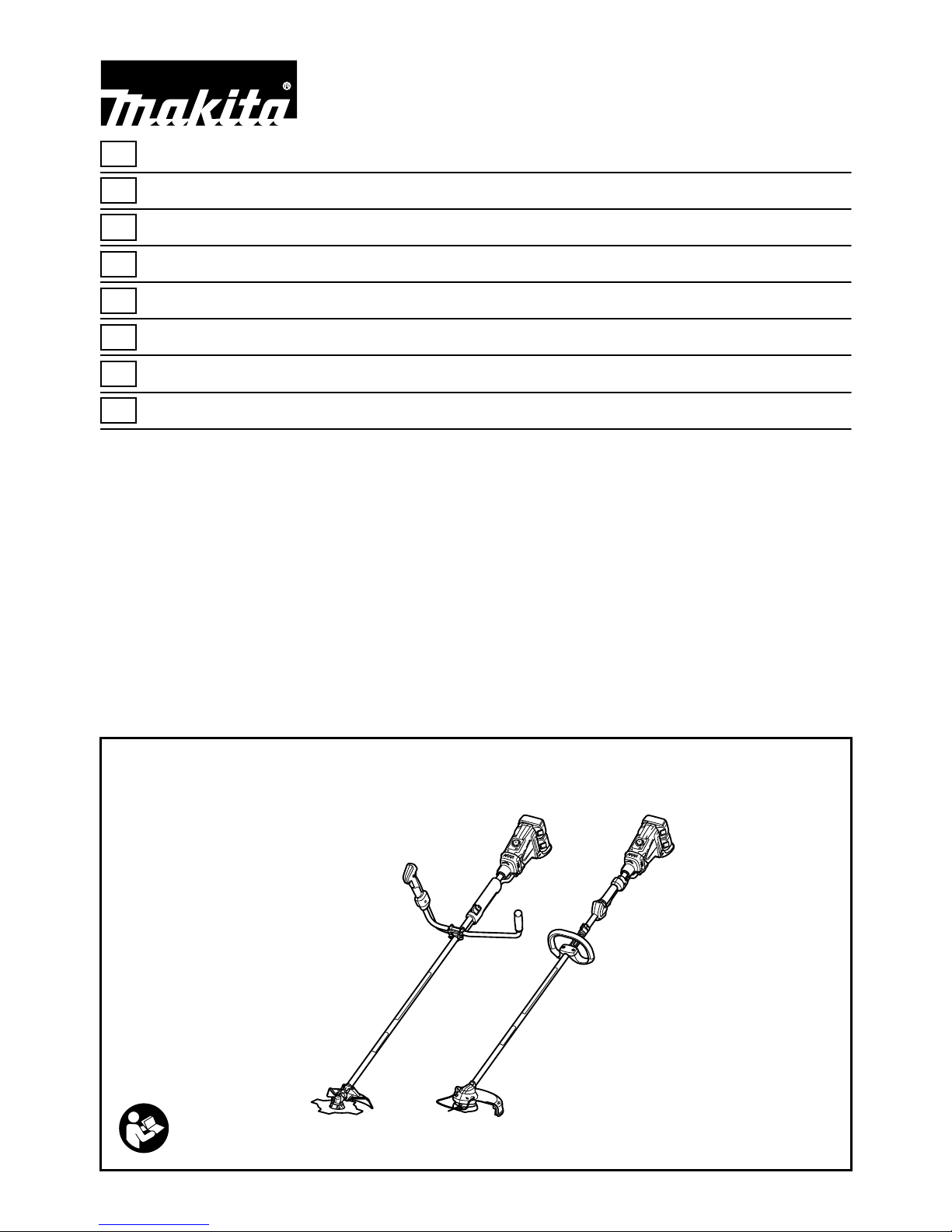
Cordless Grass Trimmer INSTRUCTION MANUAL
S
Batteridriven grästrimmer BRUKSANVISNING
N
Batteridrevet gresstrimmer BRUKSANVISNING
FIN
Akkukäyttöinen viimeistelyleikkuri KÄYTTÖOHJE
LV
Bezvada zāles trimers LIETOŠANAS INSTRUKCIJA
LT
Belaidė žoliapjovė NAUDOJIMO INSTRUKCIJA
EE
Akuga murutrimmer KASUTUSJUHEND
RUS
Аккумуляторная Коса
РУКОВОДСТВО ПО ЭКСПЛУАТАЦИИ
DUR361U
DUR362L
2
1
2
3
1 014746
1
2
2 014812
1
3 012128
1
2
4 014808
1
2
5 014812
1
2
6 013807
1
2
7 014158
1
2
3
8 013835
A
B
1
2
3
9 014159
1
10 014748
1
11 014839
1
3
2
12 012456
11
2
13 014752
1
2
4
3
5
6
14 014753
3
15 014755
1
2
3
4
5
16 014760
1
2
17 014835
1
2
20 014833
1
2
23 014762
1
2
3
4
5
26 014766
2
1
18 014836
1
2
19 014759
1
2
3
21 014834 22 014761
24 014763
1
2
3
25 014764
1
2
27 014767 28 014768

4
1
32 012478
1
35 014751
1
38 013823
41 013826
30 014750
1
2
31 014769
33 014838
1
2
34 014156
1
2
36 014840
37 013822
39 013824
40 013825
42 013827
1
29 014747

5
ENGLISH (Original instructions)
Explanation of general view
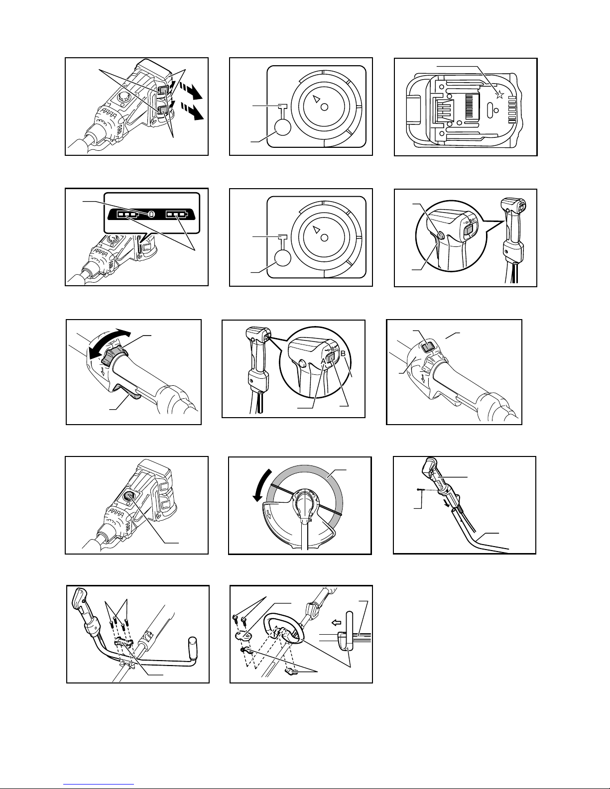
1-1. Red indicator
1-2. Button
1-3. Battery cartridge
2-1. Power indicator
2-2. Power button
3-1. Star marking
4-1. Battery indicators
4-2. Check button
5-1. Power indicator
5-2. Power button
6-1. Lock-off button
6-2. Switch trigger
7-1. Lock-off lever
7-2. Switch trigger
8-1. Reversing switch
8-2. A position depressed for normal
operation
8-3. B position depressed for weed and
debris removal
9-1. Reversing switch
9-2. A position depressed for normal
operation
9-3. B position depressed for weed and
debris removal
10-1. Speed adjusting dial
11-1. Most effective cutting area
12-1. Grip
12-2. Handle
12-3. Screw
13-1. Screw
13-2. Handle clamp
14-1. Grip
14-2. Hex bolt
14-3. Cover
14-4. Clamps
14-5. Cutting tool side
14-6. Spacer
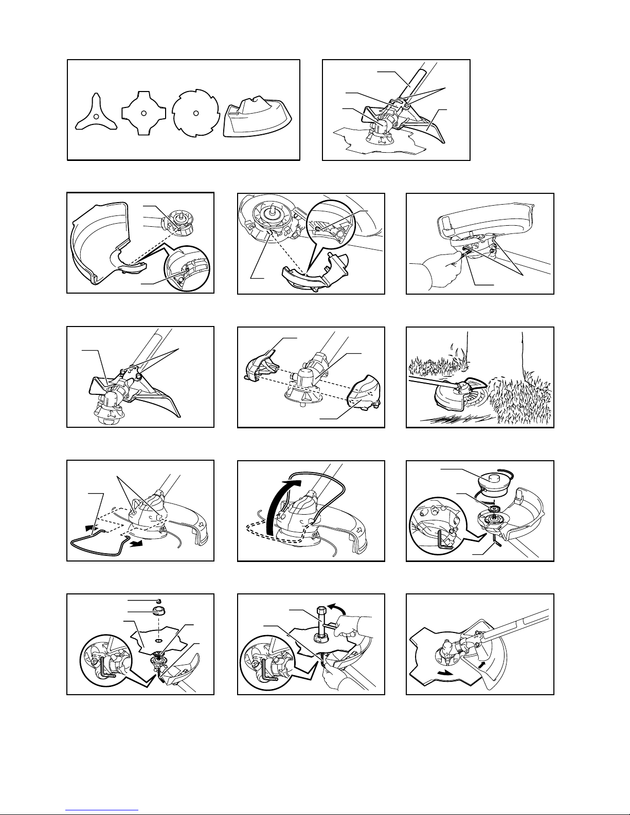
16-1. Label
16-2. Hex bolts
16-3. Protector clamp
16-4. Gear case
16-5. Protector
17-1. Protrusion
17-2. Groove
18-1. Protrusion
18-2. Groove
19-1. Hex wrench
19-2. Hex bolts
20-1. Protector
20-2. Hex bolt
21-1. Gear case
21-2. Protector holder attachment
21-3. Protector attachment
23-1. Holes
23-2. Wire guard
25-1. Nylon cutting head
25-2. Receive washer
25-3. Hex wrench
26-1. Hex nut
26-2. Clamp washer
26-3. Cutter blade
26-4. Receive washer
26-5. Hex wrench
27-1. Hex wrench
27-2. Box driver
29-1. Hex wrench
31-1. Buckle
31-2. Hook
32-1. Hanger
34-1. Buckle
34-2. Hook
35-1. Buckle
36-1. Gear case
36-2. Hex bolt
38-1. 80-100 mm
SPECIFICATIONS
Model DUR361U
Type of handle Bike handle
No load speed 3,500 - 7,300 min-1
Overall length 1,816 mm
Applicable cutting tool Cutter blade
Cutting blade diameter 230 mm
Rated voltage D.C. 36 V
Net weight 5.4 kg 5.9 kg
Standard battery cartridge BL1815N/BL1820 BL1830/BL1840/BL1850
Model DUR362L
Type of handle Loop handle
No load speed 3,500 - 6,600 min-1
Overall length 1,840 mm
Applicable cutting tool Nylon cutting head
Cutting diameter with nylon cutting head 300 mm
Rated voltage D.C. 36 V
Net weight 5.1 kg 5.6 kg
Standard battery cartridge BL1815N/BL1820 BL1830/BL1840/BL1850
• Due to our continuing program of research and development, the specifications herein are subject to change without notice.
• Specifications and battery cartridge may differ from country to country.
• Weight, with battery cartridge, according to EPTA-Procedure 01/2003
6
Noise
Sound pressure level average Sound power level average
Model LPA (dB (A))
Uncertainty K
(dB (A))
LWA (dB (A))
Uncertainty K
(dB (A))
Applicable
standard
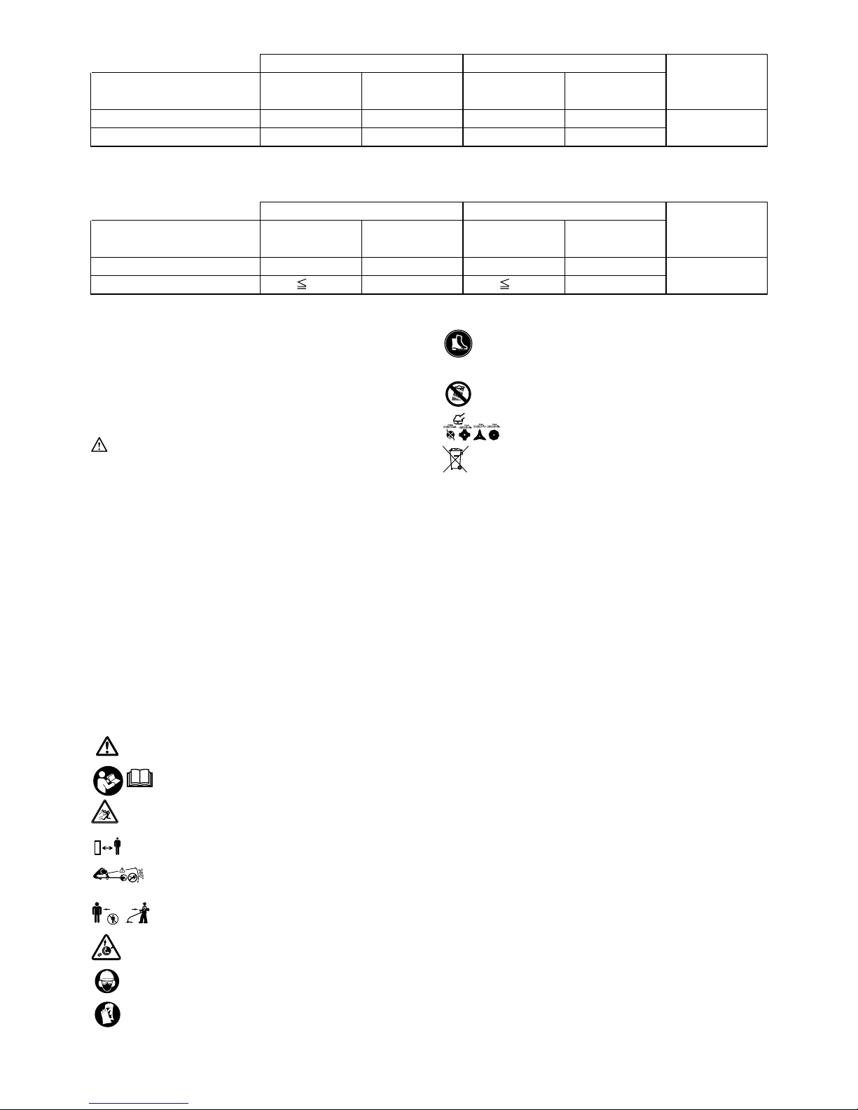
DUR361U 82 1.7 94 1.7
DUR362L 80 1.3 95 1.3
2000/14/EC
• Even if the sound pressure level listed above is 80 dB (A) or less, the level under working may exceed 80 dB (A). Wear ear
protection.
Vibration Left hand Right hand
Model ah (m/s2)
Uncertainty K
(m/s
2
)
a
h
(m/s2)
Uncertainty K
(m/s
2
)
Applicable
standard
DUR361U 2.5 1.5 2.5 1.5
DUR362L 2.5 1.5 2.5 1.5
EN786
ENG901-1
•
The declared vibration emission value has been
measured in accordance with the standard test
method and may be used for comparing one tool
with another.
• The declared vibration emission value may also be
used in a preliminary assessment of exposure.
WARNING:
• The vibration emission during actual use of the
power tool can differ from the declared emission
value depending on the ways in which the tool is
used.
• Be sure to identify safety measures to protect the
operator that are based on an estimation of
exposure in the actual conditions of use (taking
account of all parts of the operating cycle such as
the times when the tool is switched off and when it
is running idle in addition to the trigger time).
For model DUR361U
END116-1
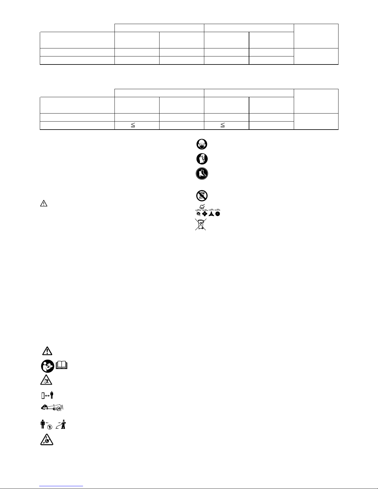
Symbols
The following show the symbols used for the equipment.
Be sure that you understand their meaning before use.
・ Take particular care and attention.
・ Read instruction manual.
・ Danger; be aware of thrown objects.
・ The distance between the tool and
bystanders must be at least 15 m.
・ Keep bystanders away.
・ Keep distance at least 15 m.
・ Avoid kickback.
・ Wear a helmet, goggles and ear
protection.
・ Wear protective gloves.
・ Wear sturdy boots with nonslip soles.
Steeltoed safety boots are
recommended.
・ Do not expose to moisture.
・ Top permissible tool speed.
・ Only for EU countries
Do not dispose of electric equipment or
battery pack together with household
waste material!
In observance of the European
Directives, on Waste Electric and
Electronic Equipment and Batteries and
Accumulators and Waste Batteries and
Accumulators and their implementation
in accordance with national laws,
electric equipment and batteries and
battery pack(s) that have reached the
end of their life must be collected
separately and returned to an
environmentally compatible recycling
facility.
ENH021-8
For European countries only
EC Declaration of Conformity
Makita declares that the following Machine(s):
Designation of Machine:
Cordless Grass Trimmer
Model No./ Type: DUR361U
Specifications: see "SPECIFICATIONS" table.
Conforms to the following European Directives:
2000/14/EC, 2006/42/EC
They are manufactured in accordance with the following
standard or standardized documents:
EN/ISO11806
The technical file in accordance with 2006/42/EC is
available from:
Makita, Jan-Baptist Vinkstraat 2, 3070, Belgium
Cd
Ni-MH
Li-ion
15m(50FT)

7
The conformity assessment procedure required by
Directive 2000/14/EC was in Accordance with annex V
Measured Sound Power Level: 94 dB (A)
Guaranteed Sound Power Level: 96 dB (A)
31.12.2013
000331
Yasushi Fukaya
Director
Makita, Jan-Baptist Vinkstraat 2, 3070, Belgium
For model DUR362L
END020-3
Symbols
The following show the symbols used for the equipment.
Be sure that you understand their meaning before use.
・ Take particular care and attention.
・ Read instruction manual.
・ Danger; be aware of thrown objects.
・ The distance between the tool and
bystanders must be at least 15 m.
・ Keep bystanders away.
・ Keep distance at least 15 m.
・ Wear a helmet, goggles and ear
protection.
・ Wear protective gloves.
・ Wear sturdy boots with nonslip soles.
Steeltoed safety boots are
recommended.
・ Do not expose to moisture.
・ Top permissible tool speed.
・ Never use metal blade.
・ Only for EU countries
Do not dispose of electric equipment or
battery pack together with household
waste material!
In observance of the European
Directives, on Waste Electric and
Electronic Equipment and Batteries and
Accumulators and Waste Batteries and
Accumulators and their implementation
in accordance with national laws,
electric equipment and batteries and
battery pack(s) that have reached the
end of their life must be collected
separately and returned to an
environmentally compatible recycling
facility.
ENH040-4
For European countries only
EC Declaration of Conformity
Makita declares that the following Machine(s):
Designation of Machine:
Cordless Grass Trimmer
Model No./ Type: DUR362L
Specifications: see "SPECIFICATIONS" table.
Conforms to the following European Directives:
2000/14/EC, 2006/42/EC
They are manufactured in accordance with the following
standard or standardized documents:
EN60335
The technical file in accordance with 2006/42/EC is
available from:
Makita, Jan-Baptist Vinkstraat 2, 3070, Belgium
The conformity assessment procedure required by
Directive 2000/14/EC was in Accordance with annex IV
Notified Body:
TÜV Rheinland LGA Products GmbH
Tillystraße 2
90431 Nürnberg, Germany
Identification number 0197
Measured sound power level 95 dB (A)
Guaranteed sound power level 96 dB (A)
31.12.2013
000331
Yasushi Fukaya
Director
Makita, Jan-Baptist Vinkstraat 2, 3070, Belgium
GEB068-5
IMPORTANT SAFETY
INSTRUCTIONS
WARNING! Read all safety warnings and all
instructions. Failure to follow the warnings and
instructions may result in electric shock, fire and/or
serious injury.
Save all warnings and
instructions for future reference.
Intended use
1. The cordless grass trimmer/ brushcutter/ string
trimmer is only intended for cutting grass, weeds,
bushes and undergrowth. It should not be used
for any other purpose such as edging or hedge
cutting as this may cause injury.
Cd
Ni-MH
Li-ion
15m(50FT)
8
General instructions
1. Never allow people unfamiliar with these
instructions, people (including children) with
reduced physical, sensory or mental capabilities,
or lack of experience and knowledge to use the
tool. Children should be supervised to ensure that
they do not play with the tool.
2. Before starting the tool, read this instruction
manual to become familiar with the handling of
the tool.
3. Do not lend the tool to a person with insufficient
experience or knowledge regarding handling of
brushcutters and string trimmers.
4. When lending the tool, always attach this
instruction manual.
5. Handle the tool with the utmost care and attention.
6. Never use the tool after consuming alcohol or
drugs, or if feeling tired or ill.
7. Never attempt to modify the tool.
8. Follow the regulations about handling of
brushcutters and string trimmers in your country.
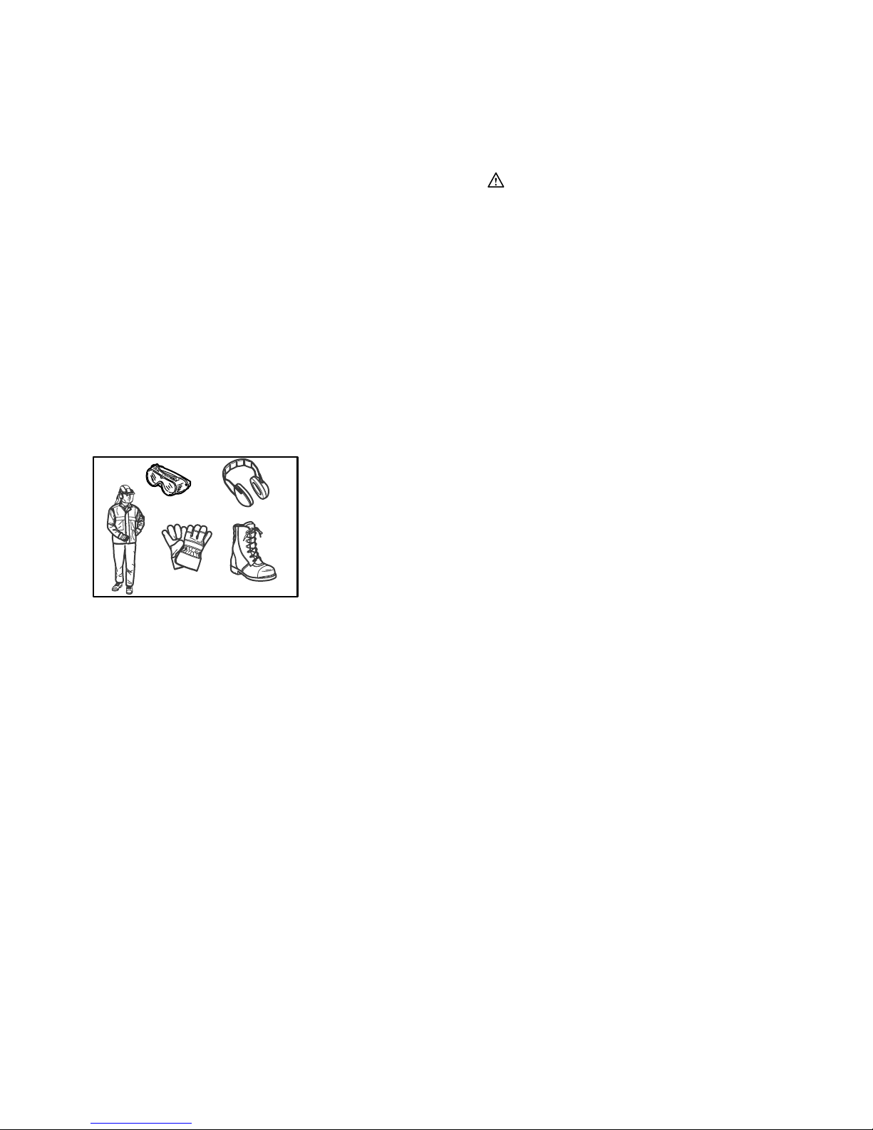
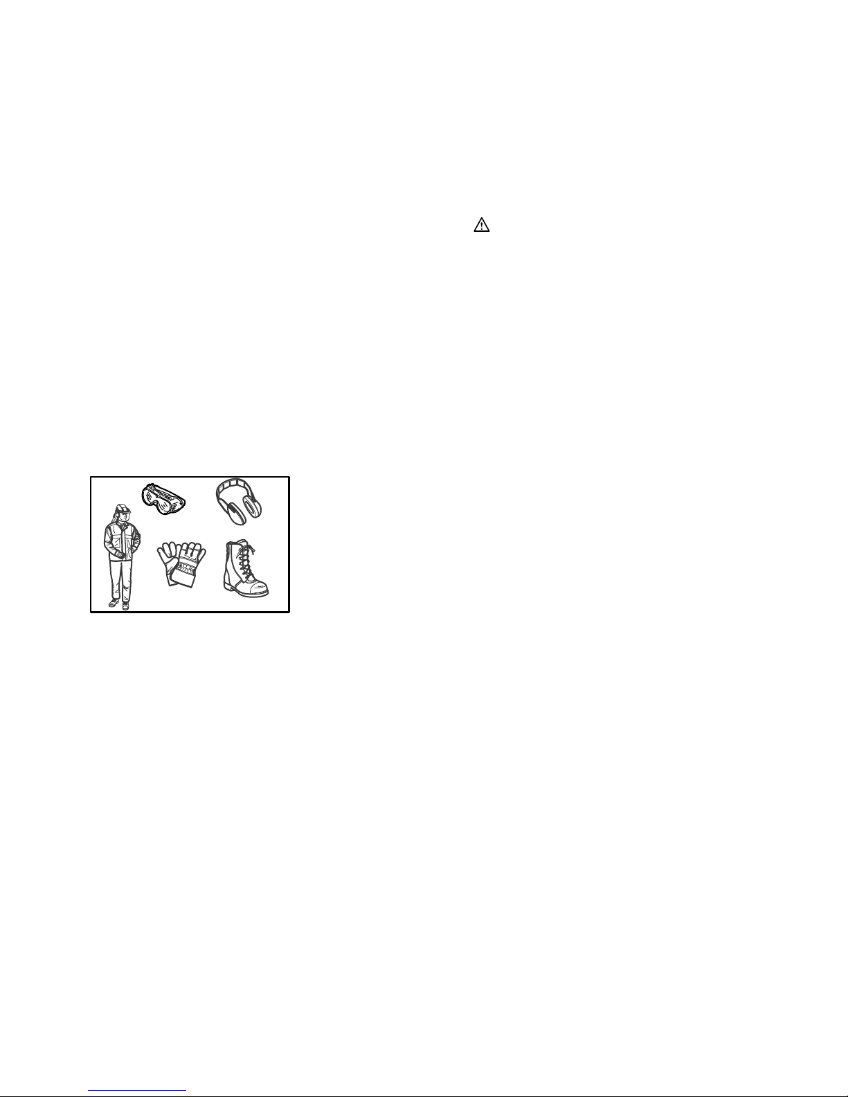
Personal protective equipment
013122
1. Wear safety helmet, protective goggles and
protective gloves to protect yourself from flying
debris or falling objects.
2. Wear ear protection such as ear muffs to prevent
hearing loss.
3. Wear proper clothing and shoes for safe
operation, such as a work overall and sturdy, nonslip shoes. Do not wear loose clothing or jewelry.
Loose clothes, jewelry or long hair can be caught
in moving parts.
4. When touching the cutting blade, wear protective
gloves. Cutting blades can cut bare hands
severely.
Work area safety
1. Operate the tool under good visibility and daylight
conditions only. Do not operate the tool in
darkness or fog.
2. Do not operate the tool in explosive atmospheres,
such as in the presence of flammable liquids,
gases or dust. The tool creates sparks which may
ignite the dust or fumes.
3. During operation, never stand on an unstable or
slippery surface or a steep slope. During the cold
season, beware of ice and snow and always
ensure secure footing.
4. During operation, keep bystanders or animals at
least 15 m away from the tool. Stop the tool as
soon as someone approaches.
5. Before operation, examine the work area for
stones or other solid objects. They can be thrown
or cause dangerous kickback and result in
serious injury and/or property damage.
6.
WARNING: Use of this product can create
dust containing chemicals which may cause
respiratory or other illnesses. Some examples of
these chemicals are compounds found in
pesticides, insecticides, fertilizers and herbicides.
Your risk from these exposures varies, depending
on how often you do this type of work. To reduce
your exposure to these chemicals: work in a well
ventilated area, and work with approved safety
equipment, such as those dust masks that are
specially designed to filter out microscopic
particles.
Electrical and battery safety
1. Do not expose the tool to rain or wet conditions.
Water entering the tool will increase the risk of
electric shock.
2. Do not use the tool if the switch does not turn it
on and off. Any tool that cannot be controlled with
the switch is dangerous and must be repaired.
3. Prevent unintentional starting. Ensure the switch
is in the off-position before installing a battery
pack, picking up or carrying the tool. Carrying the
tool with your finger on the switch or energising
the tool that have the switch on invites accidents.
4. Recharge only with the charger specified by the
manufacturer. A charger that is suitable for one
type of battery pack may create a risk of fire when
used with another battery pack.
5. Use the tool only with specifically designated
battery packs. Use of any other battery packs
may create a risk of injury and fire.
6. When battery pack is not in use, keep it away
from other metal objects, like paper clips, coins,
keys, nails, screws or other small metal objects,
that can make a connection from one terminal to
another. Shorting the battery terminals together
may cause burns or a fire.
7. Under abusive conditions, liquid may be ejected
from the battery; avoid contact. If contact
accidentally occurs, flush with water. If liquid
contacts eyes, seek medical help. Liquid ejected
from the battery may cause irritation or burns.
Putting into operation
1. Before assembling or adjusting the tool, remove
the battery cartridge.
2. Before handling the cutter blade, wear protective
gloves.
3. Before installing the battery cartridge, inspect the
tool for damages, loose screws/nuts or improper
assembly. Sharpen blunt cutter blade. If the cutter

9
blade is bent or damaged, replace it. Check all
control levers and switches for easy action. Clean
and dry the handles.
4. Never attempt to switch on the tool if it is
damaged or not fully assembled. Otherwise
serious injury may result.
5. Remove any adjusting key or wrench before
turning the tool on. A wrench or a key left
attached to a rotating part of the tool may result in
personal injury.
6. Adjust the shoulder harness and hand grip to suit
the operator's body size.
7. When inserting a battery cartridge, keep the
cutting attachment clear of your body and other
object, including the ground. It may rotate when
starting and may cause injury or damage to the
tool and/or property.
8. Remove any adjusting key, wrench or blade cover
before turning the tool on. An accessory left
attached to a rotating part of the tool may result in
personal injury.
Operation
1. In the event of an emergency, switch off the tool
immediately.
2. If you feel any unusual condition (e.g. noise,
vibration) during operation, switch off the tool. Do
not use the tool until the cause is recognized and
solved.
3. The cutting attachment continues to rotate for a
short period after turning the tool off. Don't rush to
contact the cutting attachment.
4. During operation, use the shoulder harness. Keep
the tool on your right side firmly.
5. Do not overreach. Keep proper footing and
balance at all times. Watch for hidden obstacles
such as tree stumps, roots and ditches to avoid
stumbling.
6. Never work on a ladder or tree to avoid loss of
control.
7. If the tool gets heavy impact or fall, check the
condition before continuing work. Check the
controls and safety devices for malfunction. If
there is any damage or doubt, ask our authorized
service center for the inspection and repair.
8. Do not touch the gear case. The gear case
becomes hot during operation.
9. Take a rest to prevent loss of control caused by
fatigue. We recommend taking a 10 to 20-minute
rest every hour.
10. When you leave the tool, even if it is a short time,
always remove the battery cartridge. The
unattended tool with the battery cartridge installed
may be used by unauthorized person and cause
serious accident.
11. If grass or branches get caught between the
cutting attachment and guard, always turn the
tool off and remove the battery cartridge before
cleaning. Otherwise the cutting attachment may
rotate unintentionally and cause serious injury.
12. If the cutting attachment hits stones or other hard
objects, immediately turn the tool off. Then
remove the battery cartridge and inspect the
cutting attachment.
13. Check the cutting attachment frequently during
operation for cracks or damages. Before the
inspection, remove the battery cartridge and wait
until the cutting attachment stops completely.
Replace damaged cutting attachment
immediately, even if it has only superficial cracks.
14. Never cut above waist height.
15. Before starting the cutting operation, wait until the
cutting attachment reaches a constant speed
after turning the tool on.
16. When using metal blades, swing the tool evenly
in half-circle from right to left, like using a scythe.
17. Hold the tool by insulated gripping surfaces only,
because the cutter blade may contact hidden
wiring. Cutter blades contacting a "live" wire may
make exposed metal parts of the tool "live" and
could give the operator an electric shock.
Cutting attachments
1. Use an applicable cutting attachment for the job
in hand.
− Nylon cutting heads (string trimmer heads)
are suitable for trimming lawn grass.
− Metal blades are suitable for cutting weeds,
high grasses, bushes, shrubs, underwood,
thicket, and the like.
− Never use other blades including metal multi-
piece pivoting chains and flail blades. It may
result in serious injury.
2. Always use the cutting attachment guard properly
suited for the cutting attachment used.
3. When using metal blades, avoid "kickback" and
always prepare for an accidental kickback. See
the section "Kickback."
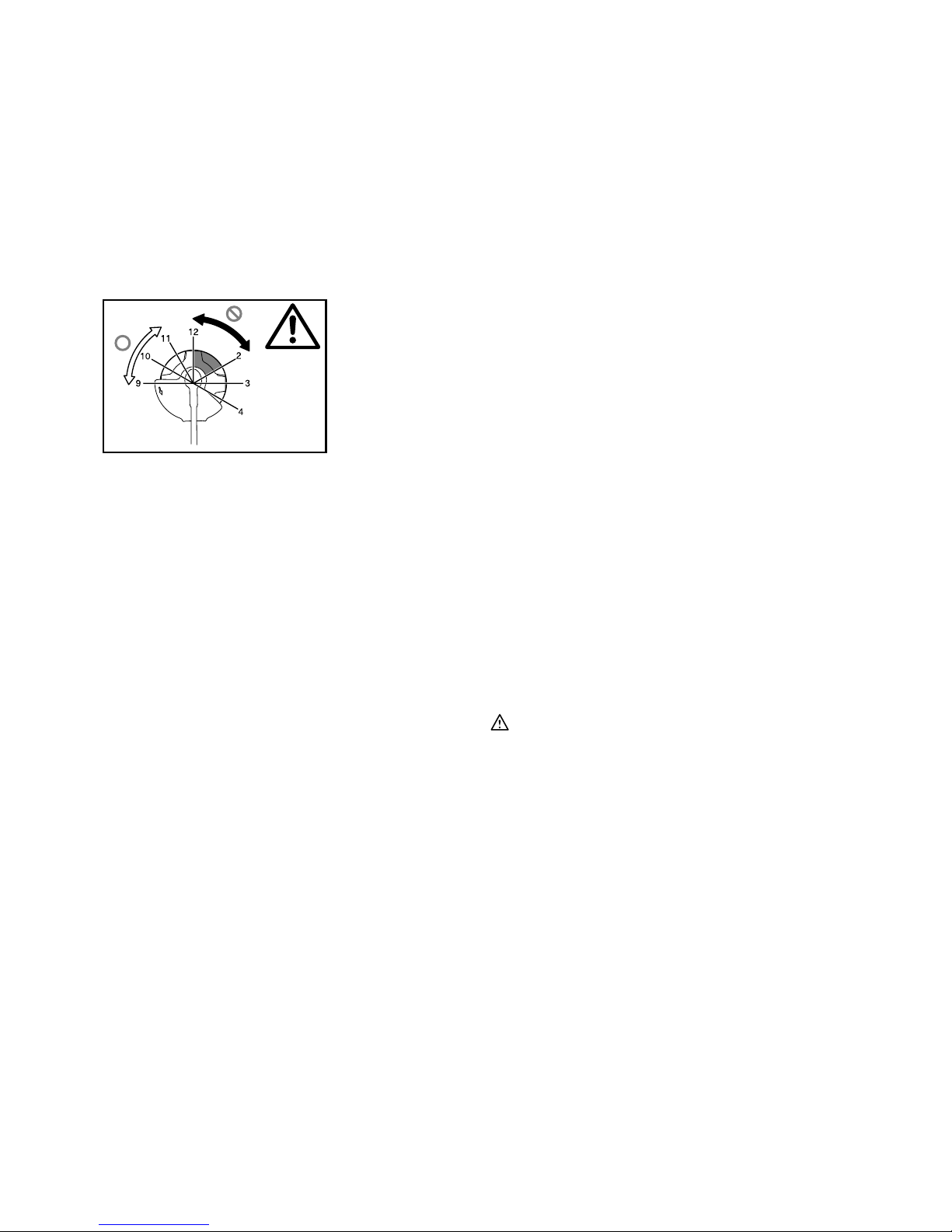
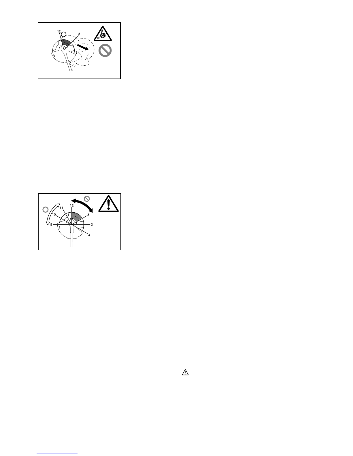
Kickback (Blade thrust)
1. Kickback (blade thrust) is a sudden reaction to a
caught or bound cutting blade. Once it occurs, the
tool is thrown sideway or toward the operator at
great force and it may cause serious injury.
2. Kickback occurs particularly when applying the
blade segment between 12 and 2 o'clock to solids,
bushes and trees with 3 cm or larger diameter.
013863
10
3. To avoid kickback:
− Apply the segment between 8 and 11 o'clock.
− Never apply the segment between 12 and 2
o'clock.
− Never apply the segment between 11 and 12
o'clock and between 2 and 5 o'clock, unless
the operator is well trained and experienced
and does it at his/her own risk.
− Never use cutting blades close to solids,
such as fences, walls, tree trunks and stones.
− Never use cutting blades vertically, for such
operations as edging and trimming hedges.
013864
Vibration
1. People with poor circulation who are exposed to
excessive vibration may experience injury to
blood vessels or the nervous system. Vibration
may cause the following symptoms to occur in the
fingers, hands or wrists: "Falling asleep"
(numbness), tingling, pain, stabbing sensation,
alteration of skin color or of the skin. If any of
these symptoms occur, see a physician!
2. To reduce the risk of "white finger disease", keep
your hands warm during operation and well
maintain the tool and accessories.
Transport
1. Before transporting the tool, turn it off and remove
the battery cartridge. Attach the cover to the
cutting blade.
2. When transporting the tool, carry it in a horizontal
position by holding the shaft.
3. When transporting the tool in a vehicle, properly
secure it to avoid turnover. Otherwise damage to
the tool and other baggage may result.
Maintenance
1. Have your tool serviced by our authorized service
center, always using only genuine replacement
parts. Incorrect repair and poor maintenance can
shorten the life of the tool and increase the risk of
accidents.
2. Before doing any maintenance or repair work or
cleaning the tool, always turn it off and remove
the battery cartridge.
3. Always wear protective gloves when handling the
cutting blade.
4. Always clean dust and dirt off the tool. Never use
gasoline, benzine, thinner, alcohol or the like for
the purpose. Discoloration, deformation or cracks
of the plastic components may result.
5. After each use, tighten all screws and nuts.
6. Do not attempt any maintenance or repair not
described in the instruction manual. Ask our
authorized service center for such work.
7.
Always use our genuine spare parts and
accessories only. Using parts or accessories
supplied by a third party may result in the tool
breakdown, property damage and/or serious injury.
8. Request our authorized service center to inspect
and maintain the tool at regular interval.
Storage
1. Before storing the tool, perform full cleaning and
maintenance. Remove the battery cartridge.
Attach the cover to the cutting blade.
2. Store the tool in a dry and high or locked location
out of reach of children.
3. Do not prop the tool against something, such as a
wall. Otherwise it may fall suddenly and cause an
injury.
First aid
1. Always have a first-aid kit close by. Immediately
replace any item taken from the first aid kit.
2. When asking for help, give the following
information:
− Place of the accident
− What happened
− Number of injured persons
− Nature of the injury
− Your name
SAVE THESE INSTRUCTIONS.
WARNING:
DO NOT let comfort or familiarity with product
(gained from repeated use) replace strict adherence
to safety rules for the subject product. MISUSE or
failure to follow the safety rules stated in this
instruction manual may cause serious personal
injury.
ENC007-8
IMPORTANT SAFETY
INSTRUCTIONS
FOR BATTERY CARTRIDGE
1. Before using battery cartridge, read all
instructions and cautionary markings on (1)
battery charger, (2) battery, and (3) product
using battery.
2. Do not disassemble battery cartridge.
3. If operating time has become excessively
shorter, stop operating immediately. It may
result in a risk of overheating, possible burns
and even an explosion.

11
4. If electrolyte gets into your eyes, rinse them
out with clear water and seek medical
attention right away. It may result in loss of
your eyesight.
5. Do not short the battery cartridge:
(1) Do not touch the terminals with any
conductive material.
(2) Avoid storing battery cartridge in a
container with other metal objects such
as nails, coins, etc.
(3) Do not expose battery cartridge to water
or rain.
A battery short can cause a large current flow,
overheating, possible burns and even a
breakdown.
6. Do not store the tool and battery cartridge in
locations where the temperature may reach or
exceed 50 ゚ C (122 ゚ F).
7. Do not incinerate the battery cartridge even if
it is severely damaged or is completely worn
out. The battery cartridge can explode in a fire.
8. Be careful not to drop or strike battery.
9. Do not use a damaged battery.
10. Follow your local regulations relating to
disposal of battery.
SAVE THESE INSTRUCTIONS.
Tips for maintaining maximum battery life
1. Charge the battery cartridge before
completely discharged.
Always stop tool operation and charge the
battery cartridge when you notice less tool
power.
2. Never recharge a fully charged battery
cartridge.
Overcharging shortens the battery service life.
3. Charge the battery cartridge with room
temperature at 10 ゚ C - 40 ゚ C (50 ゚ F - 104 ゚ F).
Let a hot battery cartridge cool down before
charging it.
4. Charge the battery cartridge once in every six
months if you do not use it for a long period
of time.

12
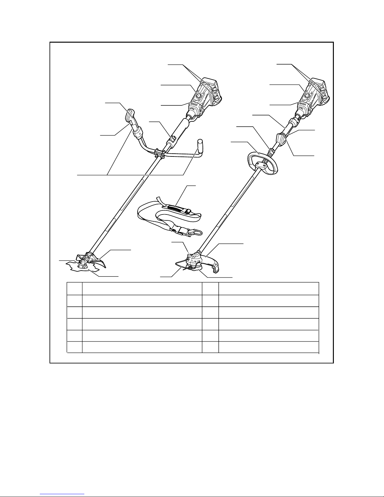
PARTS DESCRIPTION
DUR361U DUR362L
1
2
3
4
5
10
9
8
7
7
8
10
9
12
11
5
1
2
3
4
6
7
6
1
2
3
4
5
6
7
8
9
10
Battery cartridge
Speed adjusting dial
Power button
Hanger (suspension point)
Switch trigger
Grip
Wire guard
Gear case
Cutting tool
Shoulder harness11
Protector
Lock-off button / lever 12
014831
13
FUNCTIONAL DESCRIPTION
WARNING:
• Always be sure that the tool is switched off
and the battery cartridge is removed before
adjusting or checking function on the tool.
Failure to switch off and remove the battery
cartridge may result in serious personal injury from
accidental start-up.
Installing or removing battery cartridge
Fig.1
CAUTION:
• Always switch off the tool before installing or
removing of the battery cartridge.
• Hold the tool and the battery cartridge firmly
when installing or removing battery cartridge.
Failure to hold the tool and the battery cartridge
firmly may cause them to slip off your hands and
result in damage to the tool and battery cartridge
and a personal injury.
To remove the battery cartridge, slide it from the tool
while sliding the button on the front of the cartridge.
To install the battery cartridge, align the tongue on the
battery cartridge with the groove in the housing and slip
it into place. Insert it all the way until it locks in place
with a little click. If you can see the red indicator on the
upper side of the button, it is not locked completely.
CAUTION:
• Always install the battery cartridge fully until the
red indicator cannot be seen. If not, it may
accidentally fall out of the tool, causing injury to
you or someone around you.
• Do not install the battery cartridge forcibly. If the
cartridge does not slide in easily, it is not being
inserted correctly.
NOTE:
• The tool does not work with only one battery
cartridge.
Tool / battery protection system
The tool is equipped with a tool/battery protection
system. This system automatically cuts off power to the
motor to extend tool and battery life.
The tool will automatically stop during operation if the
tool or battery are placed under one of the following
conditions. In some conditions, the indicators light up.
Overload protection
When the tool is operated in a manner that causes it to
draw an abnormally high current, the tool automatically
stops and battery indicators blink. In this situation, turn
the tool off and stop the application that caused the tool
to become overloaded. Then turn the tool on to restart.
Overheat protection for tool
Fig.2
When the tool is overheated, the tool stops
automatically and the power indicator blinks about 60
seconds. In this situation, let the tool cool before turning
the tool on again.
Overheat protection for battery
When the battery is overheated, the tool stops
automatically and the battery indicators light up. The
tool does not start even if pulling the switch trigger. In
this situation, let the battery cool before turning the tool
on again.
NOTE:
The battery overheat protection works only with a
battery cartridge with a star marking.
Fig.3
Overdischarge protection
When the battery capacity becomes low, the tool stops
automatically. If the product does not operate even
when the switches are operated, remove the batteries
from the tool and charge the batteries.
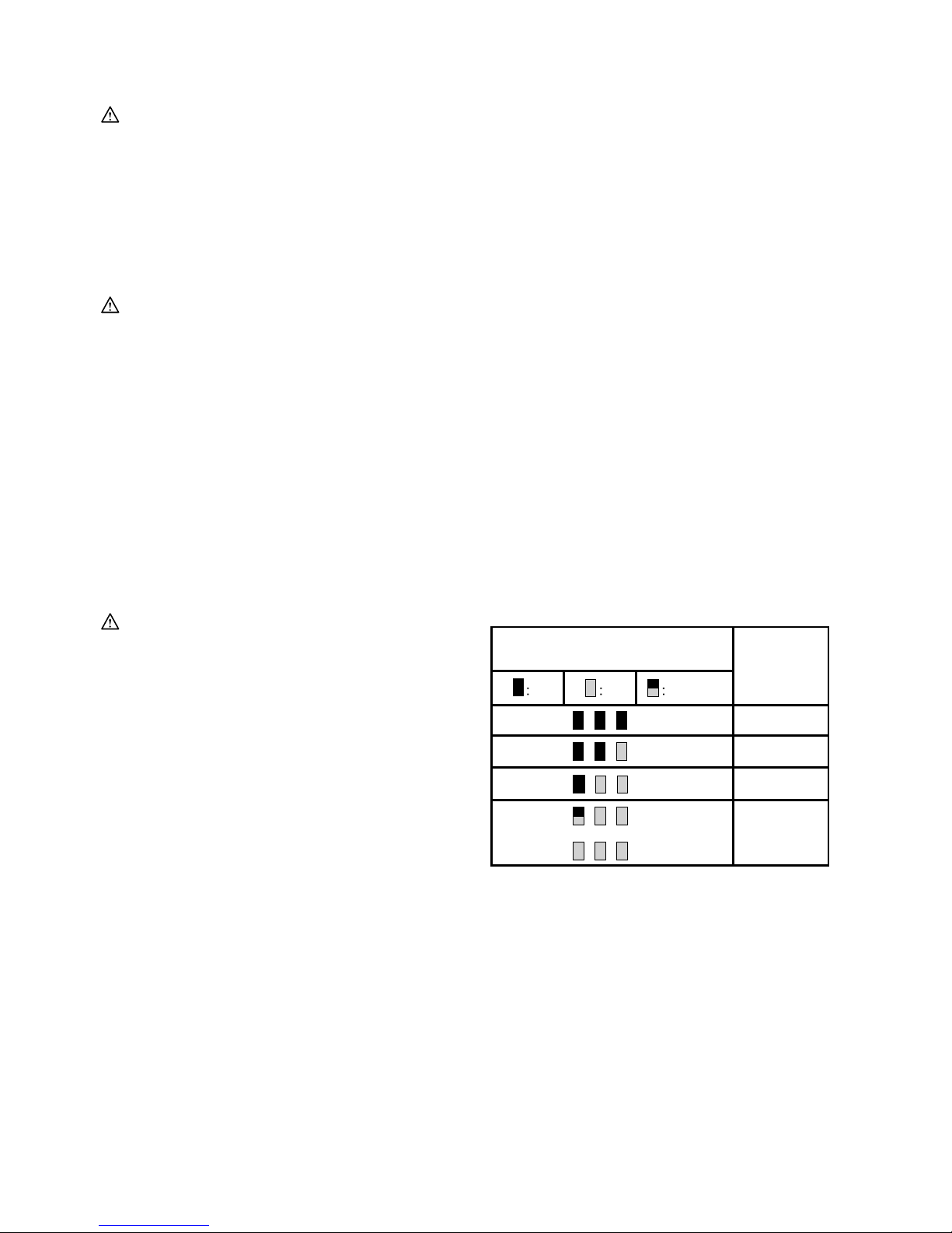
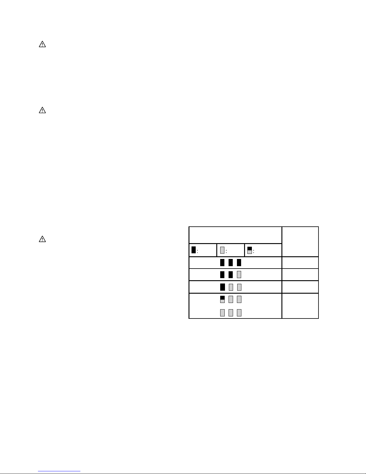
Remaining battery capacity indication
Fig.4
Press the check button to make the battery indicators
show the remaining battery capacities. The battery
indicators correspond to each battery.
Remaining battery capacity indication
Battery indicators
(Battery 1 or Battery 2)
Remaining
capacity
On Off Blinking
50% to 100%
20% to 50%
0% to 20%
or
Charge
the battery
014809
14
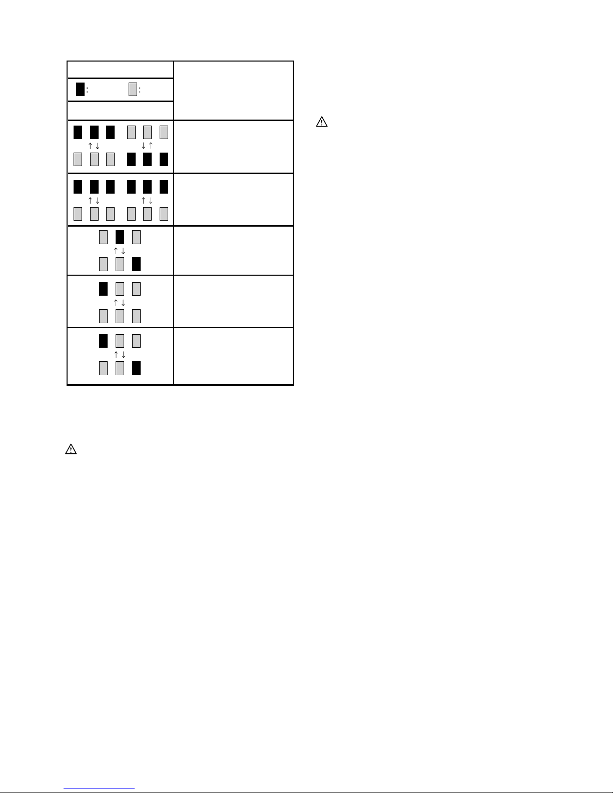
Abnormal indications during use
Battery indicator
Status
On Off
Battery 1 Battery 2
The tool may have
malfunctioned.
The tool may have
malfunctioned.
The protective function for
battery with star marking
operated (overheat).
Few remaining capacity,
charge the battery.
The tool detected an
abnormally high
voltage.
Replace battery cartridge.
014811
The indicators show various states using the remaining
battery capacity indication.
Power switch action
WARNING:
•
Before inserting the battery cartridge into the
tool, always check to see that the switch trigger
actuates properly and returns to the "OFF"
position when released. Do not pull the switch
trigger hard without turning the lock-off lever.
This can cause switch breakage.
Operating a tool
with a switch that does not actuate properly can
lead to loss of control and serious personal injury.
Fig.5
Push the power button on the housing so that the tool is
powered on and power indicator lights.
For model DUR361U
Fig.6
For model DUR362L
Fig.7
To prevent the switch trigger from being accidentally
pulled, a lock-off lever is provided.
To start the tool, turn the lock-off lever and then pull the
switch trigger. Release the switch trigger to stop.
NOTE:
• After the power button is pushed and the tool is
left one minute without any operations, the tool is
automatically powered off.
Reversing Switch for Debris Removal
WARNING:
• Always be sure that the tool is switched off
and battery cartridge is removed before
removing weeds or debris entangled in the tool
that could not be removed when operated in
the reverse mode. Failure to switch off and
remove the battery cartridge may result in serious
personal injury from accidental start-up.
For model DUR361U
Fig.8
For model DUR362L
Fig.9
This tool has a reversing switch which is only provided
to change the direction of rotation so that it can be used
to remove weeds and debris entangled in the tool. To
operate the tool normally the "A" side of the switch
should be depressed.
To remove weeds and debris that are jammed in the
rotating head the tool can be reversed by depressing
the "B" side of the switch. In the reverse position the
tool will only operate for a short period of time and
automatically shut off.
NOTICE:
• Always check the direction of rotation before
operation.
• Use the reversing switch only after the tool comes
to a complete stop. Changing the direction of
rotation before the tool stops may damage it.
Speed adjusting dial
Fig.10
The tool speed can be adjusted by turning the adjusting
dial. Turn the speed adjusting dial clockwise for higher
speed, and counterclockwise for lower speed.
Nylon cutting head (optional accessory for a
product that comes with a cutter blade)
Nylon cutting head
NOTICE:
•
Do not attempt to bump feed the head while the tool
is operating at a high RPM. Bump feeding at a high
RPM may cause damage to the nylon cutting head.
• The bump feed will not operate properly if the
head is not rotating.
Fig.11
The nylon cutting head is a dual string trimmer head
provided with a bump & feed mechanism.
To cause the nylon cord to feed out, the cutting head
should be bumped against the ground while rotating at a
low RPM.

15
NOTE:
If the nylon cord does not feed out while bumping the
head, rewind/replace the nylon cord by following the
procedures described under “Maintenance.”
ASSEMBLY
WARNING:
• Always be sure that the tool is switched off
and battery cartridge is removed before
carrying out any work on the tool. Failure to
switch off and remove the battery cartridge may
result in serious personal injury from accidental
start-up.
• Never start the tool unless it is completely
assembled. Operation of the tool in a partially
assembled state may result in serious personal
injury from accidental start-up.
Installing the handle
For model DUR361U
Fig.12
Insert the shaft of the handle into the grip as shown.
Align the screw hole in the grip with the one in the shaft.
Tighten the screw securely.
Fit the barrier and grip onto the shaft pipe with four screws.
Make sure that the spacer on the shaft pipe is located
between the grip/barrier assembly and the hanger.
Fig.13
Place handle between handle clamp and handle holder.
Adjust the handle to an angle that provides a
comfortable working position and then secure by firmly
hand-tightening knob.
For model DUR362L
Fig.14
Fit the grip onto the shaft pipe and tighten it with two
hex bolts. Make sure that the spacer on the shaft pipe is
located between the grip assembly and the other grip.
Do not remove or shrink the spacer.
Installing the guard
WARNING:
• Never use the tool without the guard illustrated
in place. Failure to do so can cause serious
personal injury.
For cutter blade (only for model DUR361U)
Fig.15
Fig.16
Install the protrusion of the protector clamp to the gear
case until aligning the position with the label on the pipe.
Fix the protector to the protector clamp with the two
bolts and then tighten both bolts by the hex wrench
evenly.
For nylon cutting head
For DUR362L
Fig.17
Align the protrusions on the protector attachment with
the grooves of the protector.
Fig.18
Align the protrusions on the protector holder attachment
with the groove of the protector holder.
Fig.19
After attaching the protector and the protector holder,
tighten the hex bolts securely.
For DUR361U (optional accessory)
Fig.20
Remove the hex bolts with hex wrench. Then remove
the protector clamp and protector.
Fig.21
Install the protector attachment and protector holder
attachment to the gear case.
To install the protector for nylon cutting head, follow the
installing method mentioned previously.
Installing the wire guard
CAUTION:
• Before adjusting the wire guard, wait for the
cutting head comes to standstill. Do not adjust the
wire guard with your foot.
Fig.22
To reduce the risk damaging the objects in front of the
cutting head, insert the wire guard so that it controls the
cutting range of the mowing line.
Fig.23
Slightly expand the wire guard outward and then insert it
into the holes of the protector.
NOTE:
• Do not expand the wire guard outward too much.
Otherwise it may break.
Fig.24
When wire guard is not in use, lift it for the idle position.
Installing nylon cutting head
CAUTION:
• If during operation the nylon cutting head
accidentally impacts a rock or hard object the
trimmer should be stopped and inspected for
any damage. If the nylon cutting head is
damaged it should be replaced immediately.
Use of a damaged nylon cutting head could result
in serious personal injury.
NOTICE:
• Be sure to use genuine Makita nylon cutting head.
Turn the tool upside down so that you can replace the
nylon cutting head easily.

16
Fig.25
Insert the hex wrench through the hole on the protector
cover and rotate the receive washer until it is locked
with the hex wrench. The nylon cutting head onto the
threaded spindle directly and tighten it by turning it
counterclockwise. Remove the hex wrench.
To remove the nylon cutting head, turn the nylon cutting
head clockwise while holding the receive washer with
the hex wrench.
Installing the cutter blade (country specific)
WARNING:
• The outside diameter of the cutter blade must
be 230 mm. Never use any blade exceeding 230
mm in outside diameter.
CAUTION:
• The cutter blade must be well polished, free of
cracks or breakage. Polish or replace the cutter
blade every three hours of operation.
• Always wear gloves when handling the cutter
blade.
• Always attach the blade cover when the tool is not
in use or is being transported.
• The cutter blade-fastening nut (with spring
washer) wears out in course of time. If there
appears any wear or deformation on the spring
washer, replace the nut. Ask your local authorized
service center to order it.
NOTICE:
• Be sure to use genuine Makita cutter blade.
Turn the tool upside down so that you can replace the
cutter blade easily.
Fig.26
To dismount the cutter blade, insert the hex wrench
through the hole on the protector cover and the gear
case. Rotate the receive washer until it is locked with
the hex wrench. Loosen the hex nut (left-hand thread)
with the socket wrench and remove the nut, clamp
washer and hex wrench.
Fig.27
Mount the cutter blade onto the shaft so that the guide
of the receive washer fits in the arbor hole in the cutter
blade. Install the clamp washer and secure the cutter
blade with the hex nut with 13 to 23 Nm of tightening
torque during holding the receive washer with hex
wrench.
Fig.28
Make sure that the blade is the left way up.
Hex wrench storage
Fig.29
When not in use, store the hex wrench as shown in the
figure to keep it from being lost.
OPERATION
Correct handling of tool (DUR361U)
Correct posture
WARNING:
• Always position the tool on your right-hand
side so that the shaft of the left handle is
always in front of your body. Correct positioning
of the tool allows for maximum control and will
reduce the risk of serious personal injury caused
by kickback.
Fig.30
As shown in the figure fit the shoulder harness and
hang the tool firmly on your right side so that the shaft of
the left handle is always ahead of you.
Attachment of shoulder harness
Fig.31
Wear the shoulder harness on your back and buckle it
up until a click is heard. Make sure that it cannot be
taken off with pulling it off. Hang the tool as shown.
WARNING:
• Be extremely careful to maintain control of the
tool at this time. Do not allow the tool to be
deflected toward you or anyone in the work
vicinity. Failure to do so could result in serious
injury.
Adjustment of the hanger position and shoulder
harness
When replacing battery or accessories with others, the
weight balance of the tool may change. In such case,
adjust the hanger position and shoulder harness length
as follows.
To change the hanger position, loosen the fixing screw
on the hanger with the supplied wrench and then move
the hanger and the cushion. The cushion can be moved
easily by twisting it.
Fig.32
Adjust the hanger position and shoulder harness length
so that:
− the hanger positions 750mm or higher from the
ground,
− the cutting tool positions 100mm to 300mm high
from the ground and
− the unguarded part of cutting tool is horizontally
750mm or farther away from the hanger.
After adjusting the hanger position, tighten the screw
with the wrench securely.
Correct handling of tool (DUR362L)
Correct posture
WARNING:
• Always position the tool on your right-hand
side so that the barrier is always in front of
your body. Correct positioning of the tool allows

17
for maximum control and will reduce the risk of
serious personal injury caused by kickback.
Fig.33
As shown in the figure, put the shoulder harness on
your left shoulder by putting your head and right arm
through it and keep the tool on your right side while
always keeping the barrier in front of your body.
Attachment of shoulder harness
Fig.34
After putting the shoulder harness on it can be attached
to the tool by connecting the buckles provided on both
the tool hook and the harness. Be sure that the buckles
click and lock completely in place.
Detachment
Fig.35
The buckle is provided with a means of quick release
which can be accomplished by simply squeezing the
sides and the buckle.
WARNING:
• Be extremely careful to maintain control of the
tool at all times. Do not allow the tool to be
deflected toward you or anyone in the work
vicinity. Failure to keep control of the tool could
result in serious injury to the bystander and the
operator.
MAINTENANCE
WARNING:
• Always be sure that the tool is switched off
and battery cartridge is removed before
attempting to perform inspection or
maintenance on the tool. Failure to switch off
and remove the battery cartridge may result in
serious personal injury from accidental start-up.
NOTICE:
Never use gasoline, benzine, thinner, alcohol or
the like. Discoloration, deformation or cracks may
result.
Supply of grease to gear case
Fig.36
Supply grease (Shell Alvania 2 or equivalent) to the
gear case. Remove the hex bolt and then put grease
through the grease hole every 30 hours. (Genuine
Makita grease may be purchased from your Makita
dealer.)
Replacing the nylon cord
WARNING:
• Make sure that the cover of the nylon cutting
head is secured to the housing properly as
described below. Failure to properly secure the
cover may cause the nylon cutting head to fly
apart resulting in serious personal injury.
Fig.37
Take off cover from housing, pressing two latches which
are slotted section oppositely on side of housing.
Fig.38
Cut a nylon line in 3-6 m. Fold the cutting line in two
halves, leave one of half longer 80-100 mm than
another.
Fig.39
Hook the middle of the new nylon cord to the notch
located at the center of the spool between the 2
channels provided for the nylon cord.
Wind both ends firmly around the spool in the direction
marked on the head for left hand direction indicated by
LH.
Fig.40
Wind all but about 100 mm of the cords, leaving the
ends temporarily hooked through a notch on the side of
the spool.
Fig.41
Mount the spool on the cover so that the grooves and
protrusions on the spool match up with those on the
cover. Now, unhook the ends of the cord from their
temporary position and feed the cords through the
eyelets to come out of the cover.
Fig.42
Align the protrusion on the underside of the cover with
the slots of the eyelets. Then push the cover firmly onto
the housing to secure it. Make sure the latches fully
spread in the cover.
To maintain product SAFETY and RELIABILITY, repairs,
any other maintenance or adjustment should be
performed by Makita Authorized Service Centers,
always using Makita replacement parts.

18
TROUBLE SHOOTING
Before asking for repairs, conduct your own inspection
first. If you find a problem that is not explained in the
manual, do not attempt to dismantle the tool. Instead,
ask Makita Authorized Service Centers, always using
Makita replacement parts for repairs.
Tighten the nut properly as described
in this manual.
Recharge the battery cartridge. If recharging
is not effective, replace battery cartridge.
Recharge the battery cartridge. If recharging
is not effective, replace battery cartridge.
Cutter blade
fastening nut is loose.
Cutter blade is fastened improperly.
The cutter blade is bended,
cracked or worn.
Malfunction status
Motor does not run.
Cause
Battery cartridges are not installed.
Battery problem (under voltage)
Rotation is in reverse.
Overheating
.
Battery power is dropping.
Electric or electronic malfunction.
Action
Install the battery cartridges.
Remove the foreign object.
Motor stops running after a little use.
It does not reach maximum RPM.
Cutting tool does not
rotate:
stop the machine immediately!
Abnormal vibration:
stop the machine immediately!
Cutting tool and motor cannot stop:
Remove the battery immediately!
Cutter blade fastening nut is loose.
Tighten the nut properly as described
in this manual.
The cutter blade is bended. Replace the cutter blade.
Replace the cutter blade.
The drive system does not work
correctly.
Battery's charge level is low.
Battery is installed improperly.
The drive system does not work
correctly.
Foreign object such as a branch is
jammed between the guard and
the nylon cutting
head.
The drive system does not work
correctly.
One end of the nylon cord has
been broken.
The drive system does not work
correctly.
Recharge the battery cartridge. If recharging
is not effective, replace battery cartridge.
Ask your l
ocal authorized service center for
repair.
Ask your local authorized service center for
repair.
Change the direction of ratation with the
reversing switch.
Stop using of tool to allow it to cool down.
Install the battery
cartridge as described in
this manual.
Ask your local authorized service center for
repair.
Ask your local authorized service center for
repair.
Bump the nylon cutting head against the
ground while it is rotating
to cause the cord
to feed.
Remove the battery cartridge and ask your
local authorized service center for repair.
014837

19
OPTIONAL ACCESSORIES
CAUTION:
• These accessories or attachments are
recommended for use with your Makita tool
specified in this manual. The use of any other
accessories or attachments might present a risk of
injury to persons. Only use accessory or
attachment for its stated purpose.
If you need any assistance for more details regarding
these accessories, ask your local Makita Service Center.
• Cutter blade
• Nylon cutting head
• Nylon cord (cutting line)
• Makita genuine battery and charger
NOTE:
• Some items in the list may be included in the tool
package as standard accessories. They may differ
from country to country.

20
SVENSKA (Originalbruksanvisning)
Förklaring till översiktsbilderna
1-1. Röd indikator
1-2. Knapp
1-3. Batterikassett
2-1. Strömindikator
2-2. Strömbrytare
3-1. Stjärnmarkering
4-1. Batteriindikeringar
4-2. CHECK-knapp
5-1. Strömindikator
5-2. Strömbrytare
6-1. Säkerhetsknapp
6-2. Avtryckare
7-1. Startspärr
7-2. Avtryckare
8-1. Reverseringsknapp
8-2. Läge A nedtryckt för normal
användning
8-3. Läge B nedtryckt för borttagning av
ogräs och skräp
9-1. Reverseringsknapp
9-2. Läge A nedtryckt för normal
användning
9-3. Läge B nedtryckt för borttagning av
ogräs och skräp
10-1. Ratt för hastighetsinställning
11-1. Effektivaste skärområde
12-1. Handtag
12-2. Handtag
12-3. Skruv
13-1. Skruv
13-2. Handtagsklämma
14-1. Handtag
14-2. Sexkantskruv
14-3. Kåpa
14-4. Klämmor
14-5. Sida med skärverktyg
14-6. Distans
16-1. Etikett
16-2. Sexkantsbultar
16-3. Skyddsklämma
16-4. Växellåda
16-5. Skydd
17-1. Tapp
17-2. Spår
18-1. Tapp
18-2. Spår
19-1. Insexnyckel
19-2. Sexkantsbultar
20-1. Skydd
20-2. Sexkantskruv
21-1. Växellåda
21-2. Skyddshållartillbehör
21-3. Skyddstillbehör
23-1. Hål
23-2. Trådskydd
25-1. Trimmerhuvud
25-2. Mottagarbricka
25-3. Insexnyckel
26-1. Sexkantmutter
26-2. Klämbricka
26-3. Fräsblad
26-4. Mottagarbricka
26-5. Insexnyckel
27-1. Insexnyckel
27-2. Hylsskruvmejsel
29-1. Insexnyckel
31-1. Spänne
31-2. Krok
32-1. Ögla
34-1. Spänne
34-2. Krok
35-1. Spänne
36-1. Växellåda
36-2. Sexkantskruv
38-1. 80–100 mm
SPECIFIKATIONER
Modell DUR361U
Handtagsmodell Cykelstyre
Obelastat varvtal 3 500 - 7 300 min-1
Längd 1 816 mm
Tillämpligt skärverktyg Fräsblad
Skärknivens diameter 230 mm
Märkspänning 36 V likström
Vikt 5,4 kg 5,9 kg
Standard batterikassett BL1815N/BL1820 BL1830/BL1840/BL1850
Modell DUR362L
Handtagsmodell Handtagsögla
Obelastat varvtal 3 500 - 6 600 min-1
Längd 1 840 mm
Tillämpligt skärverktyg Trimmerhuvud
Skärdiameter med trimmerhuvud 300 mm
Märkspänning 36 V likström
Vikt 5,1 kg 5,6 kg
Standard batterikassett BL1815N/BL1820 BL1830/BL1840/BL1850
• På grund av vårt pågående program för forskning och utveckling kan dessa specifikationer ändras utan föregående meddelande.
• Specifikationer och batterikassett kan variera från land till land.
• Vikt med batterikassett i enlighet med EPTA-procedur 01/2003
21
Buller
Genomsnittlig ljudtrycksnivå Genomsnittlig ljudeffektnivå
Modell LPA (dB (A))
Mättolerans K
(dB (A))
LWA (dB (A))
Mättolerans K
(dB (A))
Gällande
standard
DUR361U 82 1,7 94 1,7
DUR362L 80 1,3 95 1,3
2000/14/EC
• Även om ljudtrycksnivån som anges ovan är högre än 80 dB (A) eller lägre, kan nivån vid arbete överstiga 80 dB (A). Använd
hörselskydd.
Vibration Vänster hand Höger hand
Modell ah (m/s2)
Mättolerans K
(m/s
2
)
a
h
(m/s2)
Mättolerans K
(m/s
2
)
Gällande
standard
DUR361U 2,5 1,5 2,5 1,5
DUR362L 2,5 1,5 2,5 1,5
EN786
ENG901-1
•
Det deklarerade vibrationsemissionsvärdet har
uppmätts i enlighet med standardtestmetoden och
kan användas för jämförandet av en maskin med
en annan.
• Det deklarerade vibrationsemissionsvärdet kan
också användas i preliminär bedömning av
exponering för vibration.
VARNING!
• Viberationsemissionen under faktisk användning
av maskinen kan skilja sig från det deklarerade
emissionsvärdet, beroende på hur maskinen
används.
• Se till att hitta säkerhetsåtgärder som kan skydda
användaren och som grundar sig på en
uppskattning av exponering i verkligheten (ta med
i beräkningen alla delar av användandet såsom
antal gånger maskinen är avstängd och när den
körs på tomgång samt då startomkopplaren
används).
För modell DUR361U
END116-1
Symboler
Följande visar symbolerna som används för
utrustningen. Se till att du förstår innebörden innan du
använder borrmaskinen.
・ Var särskilt försiktig och uppmärksam!
・ Läs igenom bruksanvisningen.
・ Fara! Se upp för flygande föremål.
・ Avståndet mellan maskinen och
åskådare måste vara minst 15 m.
・ Håll åskådare på avstånd.
・ Håll avstånd på minst 15 m.
・ Undvik bakåtkast.
・ Använd hjälm, skyddsglasögon och
hörselskydd.
・ Bär skyddshandskar.
・ Använd kraftiga stövlar med halkfri sula.
Skyddsstövlar med stålförstärkt tåhätta
rekommenderas.
・ Utsätt inte maskinen för fukt.
・ Högsta tillåtna maskinhastighet.
・ Gäller endast EU-länder
Elektrisk utrustning eller batteripaket får
inte kastas i hushållssoporna!
Enligt EU-direktiven som avser förbrukad
elektrisk och elektronisk utrustning,
batterier, ackumulatorer, förbrukade
batterier och ackumulatorer, samt
direktivens tillämpning enligt nationell
lagstiftning, ska uttjänt elektrisk utrustning,
batterier och batteripaket sorteras separat
och lämnas till miljövänlig återvinning.
ENH021-8
Gäller endast Europa
EU-konformitetsdeklaration
Makita försäkrar att följande maskiner:
Maskinbeteckning:
Batteridriven grästrimmer
Modellnr./-typ: DUR361U
Specifikationer: se tabellen “SPECIFIKATIONER“.
Följer följande EU-direktiv:
2000/14/EU, 2006/42/EU
De är tillverkade i enlighet med följande standard eller
standardiseringsdokument:
EN/ISO11806
Den tekniska dokumentationen i enlighet med
2006/42/EG finns tillgänglig från:
Makita, Jan-Baptist Vinkstraat 2, 3070, Belgium
Cd
Ni-MH
Li-ion
15m(50FT)

22
Den bedömning av överensstämmelse som krävs av
direktiv 2000/14/EU var i enlighet med bilaga V
Uppmätt ljudeffektnivå: 94 dB (A)
Garanterad ljudeffektnivå: 96 dB (A)
31.12.2013
000331
Yasushi Fukaya
Direktör
Makita, Jan-Baptist Vinkstraat 2, 3070, Belgium
För modell DUR362L
END020-3
Symboler
Följande visar symbolerna som används för
utrustningen. Se till att du förstår innebörden innan du
använder borrmaskinen.
・ Var särskilt försiktig och uppmärksam!
・ Läs igenom bruksanvisningen.
・ Fara! Se upp för flygande föremål.
・ Avståndet mellan maskinen och
åskådare måste vara minst 15 m.
・ Håll åskådare på avstånd.
・ Håll avstånd på minst 15 m.
・ Använd hjälm, skyddsglasögon och
hörselskydd.
・ Bär skyddshandskar.
・ Använd kraftiga stövlar med halkfri sula.
Skyddsstövlar med stålförstärkt tåhätta
rekommenderas.
・ Utsätt inte maskinen för fukt.
・ Högsta tillåtna maskinhastighet.
・ Använd aldrig metallkniv.
・ Gäller endast EU-länder
Elektrisk utrustning eller batteripaket får
inte kastas i hushållssoporna!
Enligt EU-direktiven som avser förbrukad
elektrisk och elektronisk utrustning,
batterier, ackumulatorer, förbrukade
batterier och ackumulatorer, samt
direktivens tillämpning enligt nationell
lagstiftning, ska uttjänt elektrisk utrustning,
batterier och batteripaket sorteras separat
och lämnas till miljövänlig återvinning.
ENH040-4
Gäller endast Europa
EU-konformitetsdeklaration
Makita försäkrar att följande maskiner:
Maskinbeteckning:
Batteridriven grästrimmer
Modellnr./-typ: DUR362L
Specifikationer: se tabellen “SPECIFIKATIONER“.
Följer följande EU-direktiv:
2000/14/EU, 2006/42/EU
De är tillverkade i enlighet med följande standard eller
standardiseringsdokument:
EN60335
Den tekniska dokumentationen i enlighet med
2006/42/EG finns tillgänglig från:
Makita, Jan-Baptist Vinkstraat 2, 3070, Belgium
Proceduren för konformitetsbedömning som erfordras
enligt direktiv 2000/14/EU var i enlighet med tillägg IV
Anmält organ:
TÜV Rheinland LGA Products GmbH
Tillystraße 2
90431 Nürnberg, Tyskland
Identifikationsnr. 0197
Uppmätt ljudeffektnivå 95 dB (A)
Garanterad ljudeffektnivå 96 dB (A)
31.12.2013
000331
Yasushi Fukaya
Direktör
Makita, Jan-Baptist Vinkstraat 2, 3070, Belgium
GEB068-5
VIKTIGA
SÄKERHETSANVISNINGAR
VARNING! Läs igenom alla säkerhetsvarningar
och anvisningar. Underlåtenhet att följa varningar och
anvisningar kan leda till elektrisk stöt, brand och/eller
allvarliga personskador.
Spara alla varningar och
instruktioner för framtida
referens.
Avsedd användning
1. Den batteridrivna grästrimmern/röjsågen är
endast avsedd för att klippa gräs, ogräs, buskar
och undervegetation. Den ska inte användas för
något annat syfte såsom kant- eller häckklippning
eftersom detta kan orsaka skada.
Cd
Ni-MH
Li-ion
15m(50FT)
23
Allmänna anvisningar
1. Tillåt aldrig personer som inte är förtrogna med
dessa anvisningar, personer (inklusive barn) med
nedsatt fysisk, sensorisk eller mental förmåga,
eller personer utan erfarenhet av och kunskap om
maskinen att använda den. Barn ska övervakas
så att de inte leker med maskinen.
2. Läs igenom denna bruksanvisning för att bli
förtrogen med hanteringen av maskinen innan du
börjar använda den.
3. Låna inte ut maskinen till en person som inte har
tillräcklig erfarenhet eller kunskap om hanteringen
av röjsågar och trimmrar.
4. Lämna alltid över denna bruksanvisning när du
lånar ut maskinen.
5. Använd maskinen med största försiktighet och
uppmärksamhet.
6. Använd aldrig maskinen efter intag av alkohol
eller droger, eller om du känner dig trött eller sjuk.
7. Försök under inga omständigheter att modifiera
maskinen.
8. Följ föreskrifterna om hantering av röjsågar och
trimmrar i ditt land.
Personlig skyddsutrustning
013122
1. Bär skyddshjälm, skyddsglasögon och
skyddshandskar för att skydda dig mot flygande
material eller fallande föremål.
2. Bär hörselskydd såsom hörselkåpor för att
undvika hörselskador.
3. Bär lämpliga kläder och skor för säker
användning såsom arbetsoverall och kraftiga skor
med halkfri sula. Bär inte löst sittande kläder eller
smycken. Löst sittande kläder, smycken eller
långt hår kan fastna i de rörliga delarna.
4. Bär skyddshandskar när du tar i skärkniven.
Skärknivarna kan skära oskyddade händer
allvarligt.
Säkerhet på arbetsplatsen
1. Använd maskinen endast under goda
ljusförhållanden och i dagsljus. Arbeta inte med
maskinen i mörker eller dimma.
2. Använd inte maskinen i explosiva miljöer, som till
exempel i närheten av lättantändliga vätskor,
gaser eller damm. Maskinen skapar gnistor som
kan antända dammet eller ångorna.
3. Stå aldrig på ett instabilt eller halt underlag eller i
en sluttning under användningen. Var observant
på is och snö under vintersäsongen och se till att
du alltid står stadigt.
4. Håll åskådare och djur på minst 15 m avstånd
från maskinen under användningen. Stanna
maskinen så fort någon närmar sig.
5. Undersök arbetsområdet före användningen så
att det inte finns stenar eller andra fasta föremål.
De kan kastas iväg eller orsaka farliga bakåtkast
som kan resultera i allvarliga personskador
och/eller egendomsskador.
6.
VARNING: När denna produkt används kan
damm som innehåller kemikalier skapas vilket
kan ge andningssjukdomar eller andra sjukdomar.
Några exempel på dessa kemikalier är
sammansättningar som hittas i
bekämpningsmedel, insektsmedel och växtgift.
Risken för exponering varierar beroende på hur
ofta du utför denna typ av arbete. För att minska
risken för exponering av dessa kemikalier: arbeta
i ett välventilerat område och arbeta med
godkänd säkerhetsutrustning, som till exempel
dammask särskilt framtagen för att filtrera bort
mikroskopiska partiklar.
El- och batterisäkerhet
1. Utsätt inte maskinen för regn eller fukt. Vatten
som kommer in i maskinen ökar risken för
elektrisk stöt.
2. Använd inte maskinen om den inte går att starta
eller stänga av med strömbrytaren. Maskiner som
inte går att styras med strömbrytaren är farliga
och måste repareras.
3. Förhindra oavsiktlig start. Försäkra dig om att
strömbrytaren står i avstängt läge innan du
monterar ett batteri, tar upp eller bär maskinen.
Att bära maskinen med fingrarna på avtryckaren
eller förse maskinen med ström när avtryckaren
är intryckt, inbjuder till olyckor.
4. Ladda endast med den batteriladdare som
angetts av tillverkaren. En laddare som passar en
viss typ av batterier kan skapa risk för brand när
den används tillsammans med annat batteri.
5. Använd endast maskinen tillsammans med
tillhörande batterier. Om andra batterier används
finns risk för personskador och brand.
6. När batteriet inte används bör det hållas borta
från andra metallföremål som till exempel gem,
mynt, nycklar, spik, skruv eller andra små
metallföremål som kan skapa anslutning från en
terminal till en annan. Kortslutning av
batteripoolerna kan orsaka brännskador eller
brand.
7. Under hårda förhållande kan det komma vätska
ur batteriet. Undvik kontakt. Spola med vatten om
kontakt ändå råkar uppstå. Om du får vätska i
ögonen ska du uppsöka läkare. Vätska från
batteriet kan orsaka hudirritation eller ge
brännskador.

24
Förberedelser inför användning
1. Ta bort batterikassetten innan du monterar eller
justerar maskinen.
2. Använd skyddshandskar när du tar i skärkniven.
3. Innan du sätter i batteri kassetten ska du
kontrollera att maskinen inte är skadad, har lösa
skruvar/muttrar eller är felaktigt monterad. Slipa
skärkniven om den är slö. Om skärkniven är böjd
eller skadad ska den bytas ut. Kontrollera att alla
kontrollspakar och brytare fungerar korrekt.
Rengör och torka torr handtagen.
4. Försök aldrig att sätta på maskinen om den är
skadad eller inte helt monterad. Det kan i så fall
resultera i allvarliga personskador.
5. Ta bort eventuell justeringsnyckel eller skiftnyckel
innan du startar maskinen. En skiftnyckel eller
justeringsnyckel som är fäst på en roterande del
av maskinen kan ge upphov till personskador.
6. Justera axelbandet och handgreppet så att de
passar användarens storlek.
7. Håll skärtillsatsen bort från kroppen och andra
föremål, inklusive marken, när du sätter i
batterikassetten. Den kan rotera vid start och
orsaka personskador eller skada maskinen
och/eller egendom.
8. Ta bort eventuell justeringsnyckel, skiftnyckel eller
knivskydd innan du startar maskinen. Ett tillbehör
som är fäst på en roterande del av maskinen kan
ge upphov till personskador.
Användning
1. Stäng genast av maskinen i ett nödläge.
2. Stäng av maskinen om du känner att något är fel
(t.ex. buller, vibrationer) under arbetet. Använd
inte maskinen innan du vet orsaken till felet och
åtgärdat det.
3. Skärtillsatsen fortsätter att rotera en kort stund
efter det att maskinen har stängts av. Ha inte
bråttom med att röra vid skärtillsatsen.
4. Använd axelbandet när du använder maskinen.
Håll maskinen stadigt på din högra sida.
5.
Översträck inte. Stå alltid stabilt och ha god balans.
Se upp för dolda hinder såsom trädstubbar, rötter
och diken för att undvika att snubbla.
6. Stå aldrig och arbeta på en stege eller i ett träd,
för att undvika att förlora kontrollen.
7. Kontrollera maskinen innan du fortsätter att
arbeta igen om den slagit emot något hårt eller
ramlat ned. Kontrollera manöverkontrollerna och
säkerhetsenheter så att de fungerar som de ska.
Om det finns någon skada eller tveksamhet ska
du kontakta vårt auktoriserade servicecenter för
kontroll och reparation.
8. Rör inte växellådan. Växellådan blir varm under
användningen.
9. Ta en paus för att förebygga trötthet och förlorad
kontroll. Vi rekommenderar en paus på 10 till 20
minuter varje timma.
10. Ta alltid bort batterikassetten när du lämnar
maskinen även om det bara är för en kort stund.
Om batterikassetten är kvar kan en obehörig
person använda maskinen och orsaka allvarliga
olyckor.
11. Om gräs eller grenar fastnar mellan skärtillsatsen
och skyddet, ska du alltid stänga av maskinen
och ta bort batterikassetten före rengöring. I
annat fall kan skärtillsatsen rotera oavsiktligt och
orsaka allvarliga personskador.
12. Stäng genast av maskinen om skärtillsatsen slår i
stenar eller andra hårda föremål. Ta sedan bort
batterikassetten och kontrollera skärtillsatsen.
13. Kontrollera skärtillsatsen ofta under arbetet så att
det inte har uppstått sprickor eller skador. Ta bort
batterikassetten och vänta tills skärtillsatsen har
stannat helt innan du utför kontrollen. Byt genast
ut en skadad skärtillsats även om den endast har
ytliga sprickor.
14. Skär aldrig över midjehöjd.
15. Vänta tills skärtillsatsen når en konstant hastighet
efter att du startat maskinen innan du börjar
röjningsarbetet.
16. När du använder metallknivar ska du svänga
maskinen jämnt i en halvcirkel från höger till
vänster, som när du använder en lie.
17.
Håll endast i de isolerade greppen på maskinen
eftersom det finns risk för att skärkniven kan
komma i kontakt med en dold elkabel. Om
skärknivar kommer i kontakt med en strömförande
ledning blir maskinens metalldelar strömförande
och kan ge operatören en elektrisk stöt.
Skärtillsatser
1. Använd lämplig skärtillsats för det arbete som ska
utföras.
− Trimmerhuvuden (med nylontråd) är lämpliga
för att trimma gräsytor.
− Metallknivar är lämpliga vid kapning av ogräs,
högt gräs, buskage, snår, sly och liknande.
− Använd aldrig andra knivar inklusive
svängande metallkedjor och slagknivar. Det
kan orsaka allvarliga personskador.
2. Använd alltid skyddet för skärtillsatsen korrekt
fastsatt.
3. När du använder metallknivar ska du undvika
“bakåtkast” och alltid vara förberedd på
oavsiktliga bakåtkast. Se avsnittet “Bakåtkast”.
Bakåtkast (kniven slår bakåt)
1. Bakåtkast (kniven slår bakåt) är en plötslig
reaktion när en skärkniv fastnar eller studsar. När
det inträffar kastas maskinen i sidled eller mot
användaren med stor kraft och kan orsaka
allvarliga personskador.
2. Bakåtkast uppstår särskilt när man använder
kniven i segmentet mellan klockan 12 och 2 på
fasta föremål, buskar och träd med en diameter
på 3 cm eller större.
25
013863
3. För att undvika bakåtkast:
− Använd röjsågen i segmentet mellan klockan
8 och 11.
− Använd aldrig röjsågen i segmentet mellan
klockan 12 och 2.
− Använd aldrig röjsågen i segmentet mellan
klockan 11 och 12 och mellan 2 och 5,
såvida inte användaren är välutbildad och
erfaren och gör det på egen risk.
− Använd aldrig skärknivar nära fasta föremål
som till exempel staket, väggar, trädstammar
och stenar.
− Använd aldrig skärknivar vertikalt, till
exempel för kantskärning och trimning av
häckar.
013864
Vibration
1. Personer med cirkulationsrubbningar som utsätts
för kraftiga vibrationer kan drabbas av
blodutgjutningar eller skador på nervsystemet.
Vibrationer kan orsaka följande symptom i fingrar,
händer och handleder: “Domningar” (stumhet),
darrningar, smärtor, stickningar, färgförändringar i
huden och hudförändringar. Uppsök läkare om du
drabbats av något av dessa symptom!
2. För att undvika risken för “vita fingrar” ska du
hålla dina händer varma under användningen och
underhålla maskinen och tillbehören noggrant.
Transport
1. Stäng av maskinen och ta bort batterikassetten
före transport av maskinen. Montera skyddet på
skärkniven.
2. Bär maskinen i horisontalt läge genom att hålla i
skaftet när du transporterar den.
3. Fäst maskinen ordentligt så att den inte välter vid
transport i ett fordon. I annat fall kan det leda till
skada på maskinen och annat bagage.
Uunderhåll
1. Se till att din maskin servas på vårt auktoriserade
servicecenter där endast originalreservdelar
används. Felaktig reparation och dåligt underhåll
kan förkorta maskinens livslängd och öka risken
för olyckor.
2. Stäng alltid av maskinen och ta bort
batterikassetten innan du utför något underhållseller reparationsarbete eller rengör maskinen.
3. Använd alltid skyddshandskar när du hanterar
skärkniven.
4. Rengör alltid maskinen från damm och smuts.
Använd inte bensin, thinner, alkohol eller liknande
för ändamålet. Missfärgning och deformering av
eller sprickor i plastkomponenterna kan uppstå.
5. Dra åt alla skruvar och muttrar efter varje
användning.
6. Utför inget underhåll eller reparationer som inte
finns beskrivna i bruksanvisningen. Be vårt
auktoriserade servicecenter att utföra sådant
arbete.
7. Använd endast våra originalreservdelar och tillbehör. Om delar eller tillbehör från en tredje
part används kan det resultera i att maskinen går
sönder, egendomsskador och/eller allvarliga
personskador.
8. Be vårt auktoriserade servicecenter att kontrollera
och utföra underhåll på maskinen regelbundet.
Förvaring
1. Utför helrengöring och underhåll på maskinen
innan du förvarar den. Ta bort batterikassetten.
Montera skyddet på skärkniven.
2. Förvara maskinen på en torr, hög eller låst plats
utom räckhåll för barn.
3. Luta inte maskinen mot något, såsom en vägg. I
annat fall kan den plötsligt falla ned och orsaka
personskador.
Första hjälpen
1. Ha alltid förstahjälpenväskan i närheten. Se till att
förstahjälpenväskan alltid hålls komplett.
2. Ange följande information när du ber om hjälp:
− Platsen för olyckan
− Vad som hänt
− Antal skadade personer
− Skadans natur
− Ditt namn
SPARA DESSA ANVISNINGAR.
VARNING!
GLÖM INTE att noggrant följa
säkerhetsanvisningarna för maskinen även efter det
att du har blivit van att använda den. OVARSAM
hantering eller underlåtenhet att följa
säkerhetsanvisningarna i denna bruksanvisning kan
leda till allvarliga personskador.

26
ENC007-8
VIKTIGA
SÄKERHETSANVISNINGAR
FÖR BATTERIKASSETT
1. Innan batterikassetten används ska alla
instruktioner och varningsmärken på (1)
batteriladdaren, (2) batteriet och (3) produkten
läsas.
2. Montera inte isär batterikassetten.
3. Om driftstiden blivit avsevärt kortare ska
användningen avbrytas omedelbart. Det kan
uppstå överhettning, brännskador och t o m
en explosion.
4. Om du får elektrolyt i ögonen ska de sköljas
med rent vatten och läkare uppsökas
omedelbart. Det finns risk för att synen
förloras.
5. Kortslut inte batterikassetten.
(1) Rör inte vid polerna med något
strömförande material.
(2) Undvik att förvara batterikassetten
tillsammans med andra metallobjekt som
t ex spikar, mynt etc.
(3) Skydda batteriet mot vatten och regn.
Ett kortslutet batteri kan orsaka ett stort
strömflöde, överhettning, risk för brännskador
och maskinen kan till och med gå sönder.
6. Förvara inte maskinen och batterikassetten på
platser där temperaturen kan nå eller
överstiga 50 ゚ C (122 ゚ F).
7. Bränn inte upp batterikassetten även om den
är svårt skadad eller helt utsliten.
Batterikassetten kan explodera i öppen eld.
8. Var försiktig så att du inte råkar tappa batteriet
och utsätt det inte för stötar.
9. Använd inte ett skadat batteri.
10. Följ lokala föreskrifter beträffande
avfallshantering av batteriet.
SPARA DESSA ANVISNINGAR.
Tips för att uppnå batteriets maximala
livslängd
1. Ladda batterikassetten innan den är helt
urladdad.
Sluta att använda maskinen och ladda
batterikassetten när du märker att kraften
avtar.
2. Ladda aldrig en fulladdad batterikassett.
Överladdning förkortar batteriets livslängd.
3. Ladda batterikassetten vid rumstemperaturer
mellan 10 ゚ C och 40 ゚ C (50 ゚ F - 104 ゚ F). Låt
en varm batterikassett svalna innan den
laddas.
4. Ladda batterikassetten om du inte har använt
den på mer än sex månader.
27
BESKRIVNING AV DELAR
DUR361U DUR362L
1
2
3
4
5
10
9
8
7
7
8
10
9
12
11
5
1
2
3
4
6
7
6
1
2
3
4
5
6
7
8
9
10
Batterikassett
Ratt för hastighetsinställning
Strömbrytare
Bygel (upphängningspunkt)
Avtryckare
Handtag
Trådskydd
Växellåda
Skärverktyg
Axelrem11
Skydd
Säkerhetsknapp 12
014831
28
FUNKTIONSBESKRIVNING
VARNING!
• Se alltid till att maskinen är avstängd och att
batterikassetten är borttagen innan du justerar
verktyget eller kontrollerar dess funktion. I
annat fall kan det leda till allvarliga personskador
vid en oavsiktlig start.
Montera eller demontera batterikassetten
Fig.1
FÖRSIKTIGT!
• Stäng alltid av maskinen innan du monterar eller
tar bort batterikassetten.
• Håll stadigt i maskinen och batterikassetten
när du installerar eller tar bort batterikassetten.
Om du inte håller stadigt i maskinen och
batterikassetten kan de halka ur dina händer och
skadas samt orsaka personskada.
Ta bort batterikassetten genom att skjuta ner knappen
på kassettens framsida samtidigt som du drar ut
batterikassetten.
Sätt i batterikassetten genom att rikta in tungan på
batterikassetten mot spåret i höljet och skjut den på
plats. Tryck in batterikassetten ordentligt tills den låser
fast med ett klick. Om du kan se den röda indikatorn på
knappens ovansida är batterikassetten inte låst
ordentligt.
FÖRSIKTIGT!
• Sätt alltid i batterikassetten helt tills den röda
indikatorn inte längre syns. I annat fall kan den
oväntat falla ur maskinen och skada dig eller
någon annan.
• Montera inte batterikassetten med våld. Om
kassetten inte lätt glider på plats är den felinsatt.
OBS!
• Maskinen fungerar inte med endast en
batterikassett.
Skyddssystem för maskinen/batteriet
Maskinen är utrustad med ett maskin/batteriskyddssystem. Detta system bryter automatiskt
strömmen till motorn för att förlänga maskinens och
batteriets livslängd.
Maskinen stoppar automatiskt under användningen om
maskinen eller batteriet hamnar i en av följande
situationer. Indikatorerna tänds i vissa situationer.
Överbelastningsskydd
När maskinen används på ett sätt som gör att den drar
onormalt mycket ström, stoppar den automatiskt och
batteriindikeringarna blinkar. Stäng då av maskinen och
stoppa åtgärden som överbelastar maskinen. Starta
därefter maskinen för att starta om.
Överhettningsskydd för maskinen
Fig.2
När maskinen är överhettad stoppar den automatiskt
och strömindikatorn blinkar i cirka 60 sekunder. Låt då
maskinen svalna innan du startar maskinen igen.
Överhettningsskydd för batteri
När batteriet är överhettat, stoppar maskinen
automatiskt och batteriindikeringarna tänds. Maskinen
startar inte trots att du trycker in avtryckaren. Låt då
batteriet svalna innan du startar maskinen igen.
OBS!
Överhettningsskyddet för batteriet fungerar endast med
en stjärnmärkt batterikassett.
Fig.3
Överurladdningsskydd
När batteriets kapacitet är låg stoppar maskinen
automatiskt. Om produkten inte fungerar trots att
knapparna fungerar som de ska tar du bort batterierna
från maskinen och laddar dem.
Indikering av återstående batterikapacitet
Fig.4
Tryck på kontrollknappen för att batteriindikeringarna
ska visa återstående batterikapacitet.
Batteriindikeringarna motsvarar varje batteri.
Indikering av återstående batterikapacitet
Batteriindikeringar
(batteri 1 eller batteri 2)
Kvarvarande
kapacitet
ON OFF Blinkar
50 % till 100 %
20 % till 50 %
0% till 20%
eller
Ladda
batteriet
014809

29
Avvikande indikering under användning
Batteriindikator
Status
ON OFF
Batteri 1 Batteri 2
Det kan finnas ett fel på
maskinen.
Det kan finnas ett fel på
maskinen.
Skyddsfunktionen för batteri
med stjärnmärkning är
aktiverad (överhettning).
Låg återstående kapacitet,
ladda batteriet.
Maskinen detekterade en
onormalt hög spänning.
Byt ut batterikassetten.
014811
Indikatorerna visar olika tillstånd med hjälp av
indikeringen för återstående batterikapacitet.
Säkerhetsgreppfunktion
VARNING!
• Innan du sätter i batterikassetten i maskinen
ska du alltid kontrollera att avtryckaren
fungerar och att den återgår till läget “OFF”
när du släpper den. Tryck inte in avtryckaren
hårt utan att ha tryckt in säkerhetsknappen. I
annat fall kan avtryckaren gå sönder. Om du
använder en maskin med en avtryckare som inte
fungerar korrekt kan du tappa kontrollen över
maskinen och orsaka allvarliga personskador.
Fig.5
Tryck på strömbrytaren på kåpan så att maskinen slås
på och strömindikatorn tänds.
För modell DUR361U
Fig.6
För modell DUR362L
Fig.7
Säkerhetsspakens funktion är att förhindra att
avtryckaren oavsiktligt trycks in.
För att starta maskinen vrider du först in
säkerhetsspaken och trycker därefter på avtryckaren.
Släpp avtryckaren för att stanna maskinen.
OBS!
• Efter att du tryckt på strömbrytaren och maskinen
lämnats i en minut utan någon åtgärd, stängs den
automatiskt av.
Reverseringsknapp för byte av
rotationsriktning vid skräpborttagning
VARNING!
• Se alltid till att maskinen är avstängd och att
batterikassetten är borttagen innan du tar bort
ogräs eller skräp som har fastnat i maskinen
och som inte kunde tas bort när maskinen
användes i det reverserade läget. I annat fall
kan det leda till allvarlig personskada vid en
oavsiktlig start.
För modell DUR361U
Fig.8
För modell DUR362L
Fig.9
Denna maskin är utrustad med en reverseringsknapp
som endast är till för att ändra rotationsriktningen så att
den kan användas för att ta bort ogräs och skräp som
har fastnat i maskinen. För att använda maskinen
normalt ska knappen vara tryckt mot “A”-sidan.
För att ta bort ogräs och skräp som har fastnat i det
roterande huvudet kan maskinen ställas i reverserat
läge genom att trycka knappen mot “B”-sidan. I det
reverserade läget arbetar maskinen endast en kort
stund och stängs sedan automatiskt av.
OBS:
•
Kontrollera alltid rotationsriktningen före användning.
•
Använd endast reverseringsknappen när verktyget
har stoppat helt. Verktyget kan skadas om du byter
rotationsriktning medan den fortfarande roterar.
Ratt för hastighetsinställning
Fig.10
Maskinens hastighet justeras genom att du vrider på
ratten. Vrid ratten för hastighetsjustering medurs för
högre hastighet och moturs för längre hastighet.
Trimmerhuvud (valfritt tillbehör för en
produkt som levereras med en skärkniv)
Trimmerhuvud
OBS:
• Försök inte att stöta huvudet för att mata ut tråd
medan maskinen går på ett högt varvtal. I annat
fall kan det orsaka skada på trimmerhuvudet.
• Stöt- och matarfunktionen kommer inte att fungera
korrekt om huvudet inte roterar.
Fig.11
Trimmerhuvudet är ett dubbelfunktionellt
grästrimmerhuvud med en stöt- och matarmekanism.
För att mata ut nylontråd ska trimmerhuvudet stötas i
marken medan det roterar på ett lågt varvtal.

30
OBS!
Om nylontråden inte matas ut vid stöt, vira upp/byt ut
nylontråden genom att följa procedurerna som beskrivs i
avsnittet “Underhåll”.
MONTERING
VARNING!
• Se alltid till att maskinen är avstängd och att
batterikassetten är borttagen innan du utför
något arbete på maskinen. I annat fall kan det
leda till allvarlig personskada vid en oavsiktlig start.
• Starta aldrig maskinen om den inte är komplett
monterad. I annat fall kan det resultera i allvarlig
personskada på grund av oavsiktlig start.
Montering av handtaget
För modell DUR361U
Fig.12
För in skaftet för handtaget i greppet så som visas.
Rikta in skruvhålet i greppet med det i skaftet. Dra åt
skruven ordentligt.
Fäst spärren och greppet på skaftröret med fyra skruvar.
Kontrollera så att distansen på skaftröret är placerad
mellan grepp-/spärrdelen och bygeln.
Fig.13
Placera handtaget mellan handtagsklämman och
handtagsfästet.
Justera handtagets vinkel så att det ger ett bekvämt
arbetsläge och fäst det sedan genom att ordentligt dra
åt vredet med handen.
För modell DUR362L
Fig.14
Passa in greppet på skaftröret och dra åt det med två
sexkantsbultar. Se till att distansen på skaftröret är
placerad mellan greppdelen och det andra greppet. Ta
inte bort eller minska distansen.
Montering av skyddet
VARNING!
• Använd aldrig maskinen utan skyddet på plats,
såsom illustreras. I annat fall kan det orsaka
allvarlig personskada.
För skärkniv (endast för modell DUR361U)
Fig.15
Fig.16
Montera de utstickande delarna för skyddsklämman på
växellådan så att de är i linje med etiketten på röret.
Sätt fast skyddet på skyddsklämman med de två
bultarna och dra åt båda bultarna jämnt med
insexnyckeln.
För trimmerhuvud
För DUR362L
Fig.17
Rikta in den utskjutande delen på skyddstillbehöret mot
skårorna på skyddet.
Fig.18
Rikta in den utskjutande delen på
skyddshållartillbehöret mot skårorna på skyddshållaren.
Fig.19
Efter att du satt fast skyddet och skyddshållaren drar du
åt insexbultarna ordentligt.
För DUR361U (valfritt tillbehör)
Fig.20
Ta bort insexbultarna med insexnyckeln. Ta därefter bort
skyddsklämman och skyddet.
Fig.21
Montera skyddstillbehöret och skyddshållartillbehöret på
växellådan.
Följ monteringsmetoden som beskrevs tidigare för att
installera skyddet för trimmerhuvudet.
Montering av trådskyddet
FÖRSIKTIGT!
• Innan du justera trådskyddet, vänta tills
trimmerhuvudet är helt stilla. Justera inte
trådskyddet med foten.
Fig.22
För att minska risken att skada föremål framför
trimmerhuvudet för du in trådskyddet så att det
kontrollerar trimningsområdet för tråden som slår gräset.
Fig.23
För ut trådskyddet lite och för därefter in det i hålen på
skyddet.
OBS!
• För inte ut trådskyddet för mycket. Det kan i så fall
gå av.
Fig.24
Om trådskyddet inte används ska du lyfta det till
viloläget.
Montera trimmerhuvudet
FÖRSIKTIGT!
• Om trimmerhuvudet oavsiktligt slår emot en
sten eller ett hårt föremål under användningen
ska trimmern stängas av och inspekteras för
eventuella skador. Om trimmerhuvudet skadas
ska det omedelbart bytas ut. Om du använder
ett skadat trimmerhuvud kan det orsaka allvarlig
personskada.
OBS:
• Använd endast Makitas originaltrimmerhuvud.
Vänd maskinen upp och ned så att du enkelt kan byta ut
trimmerhuvudet.
 Loading...