

Makita DUR182URME, DUR182UZ User Manual
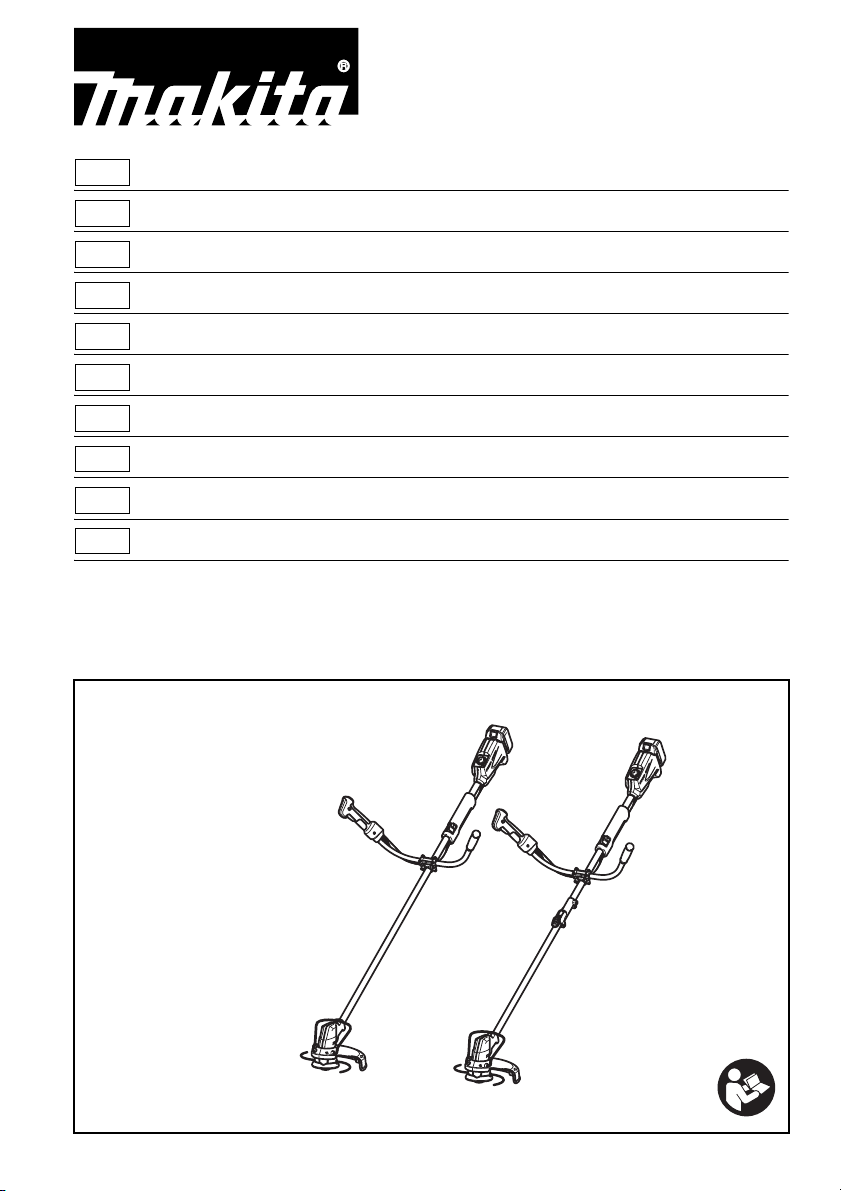
GB Cordless Grass Trimmer Instruction manual
F Coupe Herbe Sans Fil Manuel d’instructions
D Akku-Rasentrimmer Betriebsanleitung
I Tagliabordi a batteria Istruzioni per l’uso
NL Accugrastrimmer Gebruiksaanwijzing
E Cortador Inalámbrico de Pasto Manual de instrucciones
P Tesoura para grama a bateria Manual de instruções
DK Batteridreven græstrimmer Brugsanvisning
GR Χλοοκοπτικό μπαταρίας Οδηγίες χρήσης
TR Akülü Yan Tırpan Kullanım kılavuzu
DUR142U
DUR143U
DUR182U
DUR183U
013849
1 010820 2 010821
3 012858
2
1
2
3
4
5
9
7
8
6
1
2
3
4
5
9
7
8
6
10
11
12
10
11
DUR142U
DUR182U
DUR143U
DUR183U
13
14
1
15
10
4 014199
5 013921 6 013834
3
7 013807 8 013835
16
4
17
18
19
9
20
21
15
22
23
24
25
26
27
24
28
29
9 013922 10 012128
11 013836 12 013811
13 013831 14 013832
4
15 013830 16 013829
30
31
32
33
34
35
36
37
38
39
40
41
7
17 013813 18 013839
19 013838 20 013840
21 013843 22 013841
5
23 013842 24 013817
42
43
45
44
46
47
12
46
48
34
49
25 013804 26 013833
27 013805 28 013923
29 013822 30 013823
6
31 013824 32 013825
33 013826 34 013827
7

ENGLISH (Original instructions)
Explanation of general view
1. Battery cartridge
2. Indication lamp
3. Hanger (suspension point)
4. Switch trigger
5. Grip
6. Guard
7. Wire guard
8. Cutting tool
9. Speed adjusting dial
10. Power button
11. Shoulder harness
12. Cap
13. Red indicator
14. Button
15. Power indicator
16. Lock-off button
17. Reversing switch
18. A position depressed for normal
operation
19. B position depressed for weed
and debris removal
20. Star marking
21. Battery indicator
22. Most effective cutting area
23. Joint
24. Lock lever
25. Joint cover
26. Lever
27. Pipe (Cutting tool side)
28. Concave portion
29. Protrusion
30. Handle clamp
31. Groove
32. Handle holder
33. Handle
34. Hex bolt
35. Grooves
36. Protector
37. Concave portions
38. Protector holder
39. Protrusions
40. Hex bolts
41. Holes
42. Nylon cutting head
43. Metal guard
44. Receive washer
45. Hex wrench
46. Buckle
47. Hook
48. Cushion
49. 80-100 mm
SPECIFICATIONS
Model DUR142U DUR143U DUR182U DUR183U
Type of pipe Integrated pipe Splittable pipe Integrated pipe Splittable pipe
No load speed 3,500 - 6,000 min
1,843 mm
967 mm
Overall length
—
(Cutting tool side
including cap)
982 mm
(Battery side)
Cutting diameter with nylon cutting head 300 mm
Net weight 4.0 kg 4.2 kg 4.1 kg 4.3 kg
Rated voltage D.C. 14.4 V D.C. 18 V
Standard battery cartridge and charger
Always keep the combinations of
BL1430, BL1440/DC18RC BL1830, BL1840/DC18RC
battery/charger on the right columns.
• Due to our continuing program of research and development, the specifications herein are subject to change without
notice.
• Specifications and battery cartridge may differ from country to country.
• Weight, with battery cartridge, according to EPTA-Procedure 01/2003
Noise Sound pressure level
Model L
(dB (A)) Uncertainty K (dB (A))
PA
DUR142U/DUR143U 78 1.0
DUR182U/DUR183U 79 0.7
• Even if the sound pressure level listed above is 80 dB (A) or less, the level under working may exceed 80 dB (A). Wear
ear protection.
Vibration Left hand Right hand
Model a
(m/s2)
h
Uncertainty K
2
)
(m/s
a
h
(m/s2)
DUR142U/DUR143U 2.5 1.5 2.5 1.5
DUR182U/DUR183U 2.5 1.5 2.5 1.5
-1
—
Uncertainty K
2
)
(m/s
967 mm
(Cutting tool side
including cap)
982 mm
(Battery side)
Applicable standard or
directive
2000/14/EC
Applicable standard
or directive
EN786
8
• The declared vibration emission value has been
Cd
Ni-MH
Li-ion
ENG901-1
measured in accordance with the standard test method
and may be used for comparing one tool with another.
• The declared vibration emission value may also be
used in a preliminary assessment of exposure.
WARNING:
• The vibration emission during actual use of the power
tool can differ from the declared emission value
depending on the ways in which the tool is used.
• Be sure to identify safety measures to protect the
operator that are based on an estimation of exposure in
the actual conditions of use (taking account of all parts
of the operating cycle such as the times when the tool
is switched off and when it is running idle in addition to
the trigger time).
Symbols
END020-3
The following show the symbols used for the equipment.
Be sure that you understand their meaning before use.
.................... Take particular care and attention.
........ Read instruction manual.
.................. Danger; be aware of thrown objects.
.................. The distance between the tool and
bystanders must be at least 15 m.
.......... Keep bystanders away.
.......... Keep distance at least 15 m.
.................. Wear a helmet, goggles and ear
protection.
.................. Wear protective gloves.
.................. Wear sturdy boots with nonslip soles.
Steeltoed safety boots are
recommended.
.................. Do not expose to moisture.
batteries and battery pack(s) that have
reached the end of their life must be
collected separately and returned to an
environmentally compatible recycling
facility.
For European countries only
ENH219-2
EC Declaration of Conformity
We Makita Corporation as the responsible
manufacturer declare that the following Makita
machine(s):
Designation of Machine:
Cordless Grass Trimmer
Model No./Type: DUR142U, DUR143U, DUR182U,
DUR183U
Specifications: see “SPECIFICATIONS” table.
are of series production and
Conforms to the following European Directives:
2000/14/EC, 2006/42/EC
And are manufactured in accordance with the following
standards or standardised documents:
EN60335
The technical documentation is kept by:
Makita International Europe Ltd.
Technical Department,
Michigan Drive, Tongwell,
Milton Keynes, Bucks MK15 8JD, England
The conformity assessment procedure required by
Directive 2000/14/EC was in Accordance with annex VI.
Notified Body:
TÜV Rheinland LGA Products GmbH
Tillystraße 2
90431 Nürnberg, Germany
Identification number 0197
Model DUR142U, DUR143U
Measured Sound Power Level: 89 dB (A)
Guaranteed Sound Power Level: 90 dB (A)
Model DUR182U, DUR183U
Measured Sound Power Level: 90 dB (A)
Guaranteed Sound Power Level: 90 dB (A)
5. 3. 2013
................... Top permissible tool speed.
............ Never use metal blade.
............ Only for EU countries
Do not dispose of electric equipment or
battery pack together with household
waste material!
In observance of the European
Directives, on Waste Electric and
Electronic Equipment and Batteries
and Accumulators and Waste Batteries
and Accumulators and their
implementation in accordance with
national laws, electric equipment and
Tomoyasu Kato
Director
Makita Corporation
3-11-8, Sumiyoshi-cho,
Anjo, Aichi, 446-8502, JAPAN
IMPORTANT SAFETY
INSTRUCTIONS
WARNING! Read all safety warnings and all
instructions. Failure to follow the warnings and
instructions may result in electric shock, fire and/or
serious injury.
GEB109-3
9

Save all warnings and instructions for
future reference.
1. Be familiar with the controls and proper use of the
equipment.
2. Cutting elements continue to rotate after the
motor is switched off.
3. Never allow children or people unfamiliar with the
instructions to use the machine.
4. Stop using the machine while people, especially
children, or pets are nearby.
5. Only use the machine in daylight or good artificial
light.
6. Before using the machine and after any impact,
check for signs of wear or damage and repair as
necessary.
7. Take care against injury from any device fitted for
trimming the filament line length. After extending
new cutter line always return the machine to its
normal operating position before switching on.
8. Never fit metal cutting elements.
9. This appliance is not intended for use by persons
(including children) with reduced physical,
sensory or mental capabilities, or lack of
experience and knowledge, unless they have been
given supervision or instruction concerning use
of the appliance by a person responsible for their
safety. Children should be supervised to ensure
that they do not play with the appliance.
10. Use the tool with the utmost care and attention.
11. Operate the tool only if you are in good physical
condition. Perform all work calmly and carefully.
Use common sense and keep in mind that the
operator or user is responsible for accidents or
hazards occurring to other people or their
property.
12. Never operate the tool when tired, feeling ill or
under the influence of alcohol or drugs.
13. The tool should be switched off immediately if it
shows any signs of unusual operation.
Intended use of the tool
1. Use right tool. The cordless grass trimmer is only
intended for cutting grass, light weeds. It should
not be used for any other purpose such as hedge
cutting as this may cause injury.
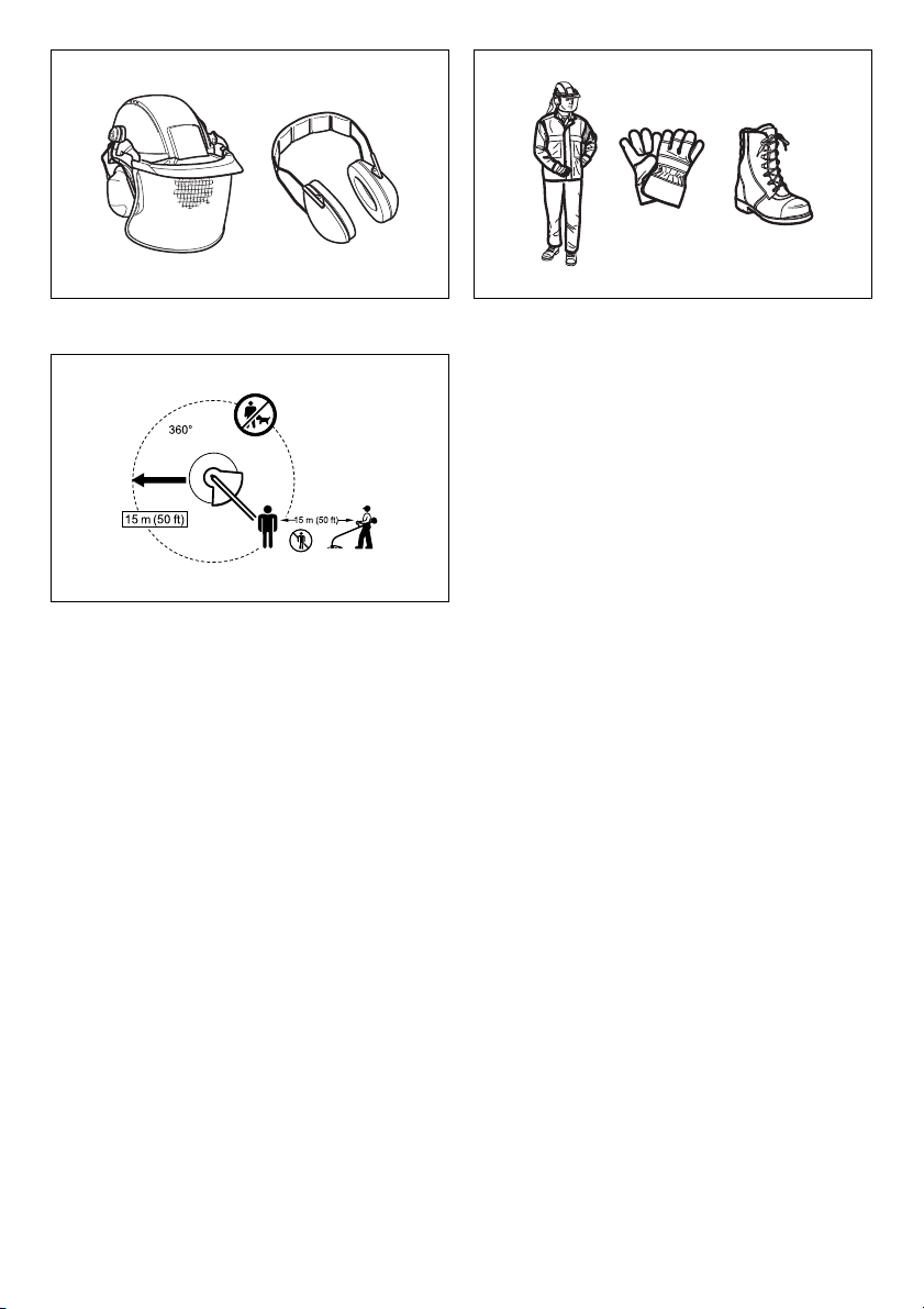
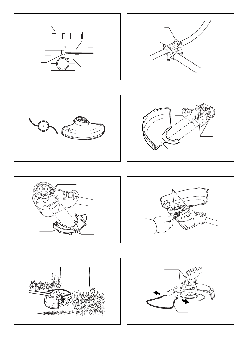
Personal protective equipment (Fig. 1 & 2)
1. Dress properly. The clothing worn should be
functional and appropriate, i.e. it should be tightfitting but not cause hindrance. Do not wear either
jewelry or clothing which could become entangled
with high grass. Wear protective hair covering to
contain long hair.
2. When using the tool, always wear sturdy shoes
with a non-slip sole. This protects against injuries
and ensures a good footing.
3. Wear protective glasses or goggles.
Electrical and battery safety
1. Avoid dangerous environment. Don’t use the tool
in damp or wet locations or expose it to rain.
Water entering the tool will increase the risk of
electric shock.
2. Recharge only with the charger specified by the
manufacturer. A charger that is suitable for one
type of battery pack may create a risk of fire when
used with another battery pack.
3. Use power tools only with specifically designated
battery packs. Use of any other battery packs may
create a risk of injury and fire.
4. When battery pack is not in use, keep it away from
other metal objects, like paper clips, coins, keys,
nails, screws or other small metal objects, that
can make a connection from one terminal to
another. Shorting the battery terminals together
may cause burns or a fire.
5. Under abusive conditions, liquid may be ejected from
the battery; avoid contact. If contact accidentally
occurs, flush with water. If liquid contacts eyes, seek
medical help. Liquid ejected from the battery may
cause irritation or burns.
6. Do not dispose of the battery(ies) in a fire. The cell
may explode. Check with local codes for possible
special disposal instructions.
7. Do not open or mutilate the battery(ies). Released
electrolyte is corrosive and may cause damage to
the eyes or skin. It may be toxic if swallowed.
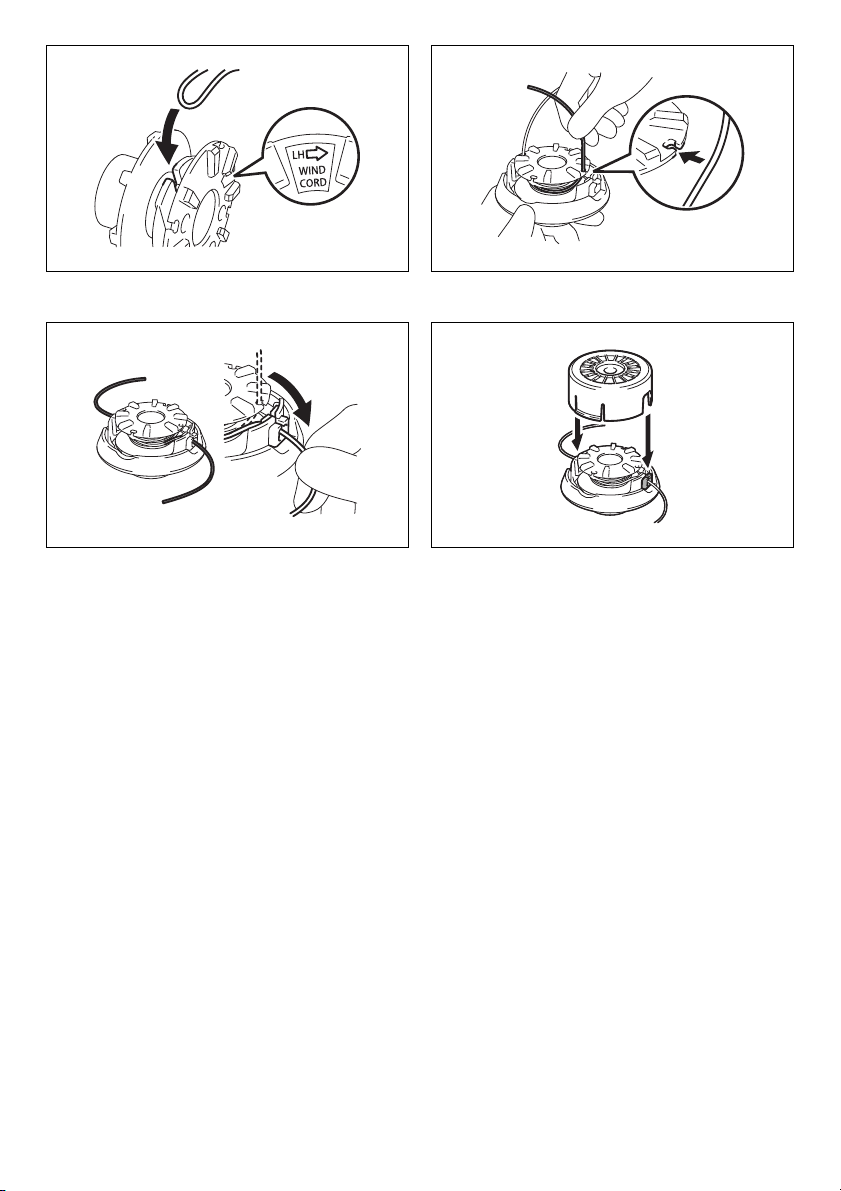
Starting up the tool (Fig. 3)
1. Make sure that there are no children or other
people within a working range of 15 meters (50 ft),
also pay attention to any animals in the working
vicinity. Otherwise stop using the tool.
2. Before use always check that the tool is safe for
operation. Check the security of the cutting tool
and the guard and the switch trigger/lever for easy
and proper action. Check for clean and dry
handles and test the on/off function of the switch.
3. Check damaged parts before further use of the
tool. A guard or other part that is damaged should
be carefully checked to determine that it will
operate properly and perform its intended
function. Check for alignment of moving parts,
binding of moving parts, breakage of parts,
mounting, and any other condition that may affect
its operation. A guard or other part that is
damaged should be properly repaired or replaced
by our authorized service center unless indicated
elsewhere in this manual.
4. Switch on the motor only when hands and feet are
away from the cutting tool.
5. Before starting make sure that the cutting tool has
no contact with hard objects such as branches,
stones etc. as the cutting tool will revolve when
starting.
Method of operation
1. Never operate the machine with damaged guards
or without the guards in place.
2. Only use the tool in good light and visibility.
During the winter season beware of slippery or
wet areas, ice and snow (risk of slipping). Always
ensure a safe footing.
3. Take care against injury to feet and hands from
the cutting tool.
4. Keep hands and feet away from the cutting means
at all times and especially when switching on the
motor.
5. Never cut above waist height.
6. Never stand on a ladder and run the tool.
10

7. Never work on unstable surfaces.
8. Don’t overreach. Keep proper footing and balance
at all times.
9. Remove sand, stones, nails etc. found within the
working range. Foreign particles may damage the
cutting tool and can cause to be thrown away,
resulting in a serious injury.
10. Should the cutting tool hit stones or other hard
objects, immediately switch off the motor and
inspect the cutting tool.
11. Before commencing cutting, the cutting tool must
have reached full working speed.
12. During operation always hold the tool with both
hands. Never hold the tool with one hand during
use. Always ensure a safe footing.
13. All protective equipment such as guards supplied
with the tool must be used during operation.
14. Except in case of emergency, never drop or cast
the tool to the ground or this may severely
damage the tool.
15. Never drag the tool on the ground when moving
from place to place, the tool may become
damaged if moved in this manner.
16. Always remove the battery cartridge from the tool:
- whenever leaving the tool unattended;
- before clearing a blockage;
- before checking, cleaning or working on the
tool;
- before making any adjustments, changing
accessories or storing;
- whenever the tool starts vibrating unusually;
- whenever transporting the tool.
17. Don’t force the tool. It will do the job better and
with less likelihood of a risk of injury at the rate for
which it was designed.
Maintenance instructions
1. The condition of the cutting tool, protective
devices and shoulder strap must be checked
before commencing work.
2. Turn off the motor and remove the battery
cartridge before carrying out maintenance,
replacing the cutting tool and cleaning the tool.
3. After use, disconnect the battery cartridge from
the tool and check for damage.
4. Check for loose fasteners and damaged parts
such as nearly halfway cut-off state in the cutting
tool.
5. When not in use store the equipment in a dry
location that is locked up or out of children’s
reach.
6. Use only the manufacturer’s recommended
replacement parts and accessories.
7. Always ensure that ventilation openings are kept
clear of debris.
8. Inspect and maintain the tool regularly, especially
before/after use. Have the tool repaired only by
our authorized service center.
9. Keep handles dry, clean and free from oil and
grease.
SAVE THESE INSTRUCTIONS.
WARNING:
DO NOT let comfort or familiarity with product (gained
from repeated use) replace strict adherence to safety
rules for the subject product. MISUSE or failure to
follow the safety rules stated in this instruction
manual may cause serious personal injury.
IMPORTANT SAFETY
INSTRUCTIONS ENC007-8
FOR BATTERY CARTRIDGE
1. Before using battery cartridge, read all
instructions and cautionary markings on (1)
battery charger, (2) battery, and (3) product using
battery.
2. Do not disassemble battery cartridge.
3. If operating time has become excessively shorter,
stop operating immediately. It may result in a risk
of overheating, possible burns and even an
explosion.
4. If electrolyte gets into your eyes, rinse them out
with clear water and seek medical attention right
away. It may result in loss of your eyesight.
5. Do not short the battery cartridge:
(1) Do not touch the terminals with any
conductive material.
(2) Avoid storing battery cartridge in a container
with other metal objects such as nails, coins,
etc.
(3) Do not expose battery cartridge to water or
rain.
A battery short can cause a large current flow,
overheating, possible burns and even a
breakdown.
6. Do not store the tool and battery cartridge in
locations where the temperature may reach or
exceed 50°C (122°F).
7. Do not incinerate the battery cartridge even if it is
severely damaged or is completely worn out. The
battery cartridge can explode in a fire.
8. Be careful not to drop or strike battery.
9. Do not use a damaged battery.
10. Follow your local regulations relating to disposal
of battery.
SAVE THESE INSTRUCTIONS.
Tips for maintaining maximum battery life
1. Charge the battery cartridge before completely
discharged.
Always stop tool operation and charge the battery
cartridge when you notice less tool power.
2. Never recharge a fully charged battery cartridge.
Overcharging shortens the battery service life.
3. Charge the battery cartridge with room
temperature at 10°C - 40°C (50°F - 104°F). Let a hot
battery cartridge cool down before charging it.
4. Charge the battery cartridge once in every six
months if you do not use it for a long period of
time.
11

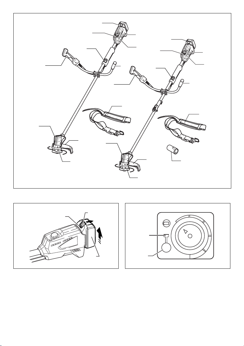
Parts description (Fig. 4)
FUNCTIONAL DESCRIPTION
WARNING:
• Always be sure that the tool is switched off and
battery cartridge is removed before adjusting or
checking the functions on the tool. Failure to switch
off and remove the battery cartridge may result in
serious personal injury from accidental start-up.
Installing or removing battery cartridge
(Fig. 5)
CAUTION:
• Always switch off the tool before installing or removing
of the battery cartridge.
• Hold the tool and the battery cartridge firmly when
installing or removing battery cartridge. Failure to
hold the tool and the battery cartridge firmly may cause
them to slip off your hands and result in damage to the
tool and battery cartridge and a personal injury.
To remove the battery cartridge, slide it from the tool while
sliding the button on the front of the cartridge.
To install the battery cartridge, align the tongue on the
battery cartridge with the groove in the housing and slip it
into place. Insert it all the way until it locks in place with a
little click. If you can see the red indicator on the upper
side of the button, it is not locked completely.
CAUTION:
• Always install the battery cartridge fully until the red
indicator cannot be seen. If not, it may accidentally fall
out of the tool, causing injury to you or someone
around you.
• Do not install the battery cartridge forcibly. If the
cartridge does not slide in easily, it is not being inserted
correctly.
Power switch action
WARNING:
• Before inserting the battery cartridge in the tool,
always check to see that the switch trigger
actuates properly and returns to the “OFF”
position when released. Do not pull the switch
trigger hard without pressing in the lock-off button.
This can cause switch breakage. Operating a tool
with a switch that does not actuate properly can lead to
loss of control and serious personal injury. (Fig. 6)
Push the power button on the housing so that the tool is
powered on and power indicator lights. (Fig. 7)
To prevent the switch trigger from being accidentally
pulled, a lock-off button is provided.
To start the tool, press in the lock-off button and pull the
switch trigger. Release the switch trigger to stop.
NOTE:
• After the power button is pushed and the tool is left one
minute without any operations, the tool is automatically
powered off.
Reversing switch for debris removal
WARNING:
• Always be sure that the tool is switched off and
battery cartridge is removed before removing
weeds or debris entangled in the tool that could not
be removed when operated in the reverse mode.
Failure to switch off and remove the battery cartridge
may result in serious personal injury from accidental
start-up. (Fig. 8)
This tool has a reversing switch which is only provided to
change the direction of rotation so that it can be used to
remove weeds and debris entangled in the tool. To
operate the tool normally the “A” side of the switch should
be depressed.
To remove weeds and debris that are jammed in the
rotating head the tool can be reversed by depressing the
“B” side of the switch. In the reverse position the tool will
only operate for a short period of time and automatically
shut off.
NOTICE:
• Always check the direction of rotation before operation.
• Use the reversing switch only after the tool comes to a
complete stop. Changing the direction of rotation
before the tool stops may damage it.
Speed adjusting dial (Fig. 9)
The tool speed can be infinitely adjusted from 3,500 min-1
to 6,000 min
Turn the speed adjusting dial clockwise for higher speed,
and counterclockwise for lower speed.
-1
with the speed adjusting dial.
Battery protection system (Lithium-ion
battery with star marking) (Fig. 10)
Lithium-ion batteries with a star marking are equipped
with a protection system. This system automatically cuts
off power to the tool to extend battery life.
The tool will automatically stop during operation if the tool
and/or battery are placed under one of the following
conditions:
• Overloaded:
The tool is operated in a manner that causes it to
draw an abnormally high current.
In this situation, release the switch trigger on the tool
and stop the application that caused the tool to
become overloaded. Then pull the switch trigger
again to restart.
If the tool does not start, the battery is overheated. In
this situation, let the battery cool before pulling the
switch trigger again.
• Low battery voltage:
The remaining battery capacity is too low and the tool
will not operate. In this situation, remove and
recharge the battery.
Indication lamps (Fig. 11)
When the protection system works during the operation,
the lamps light up.
Refer to the following table for the status and action to be
taken for the indication lamp.
12

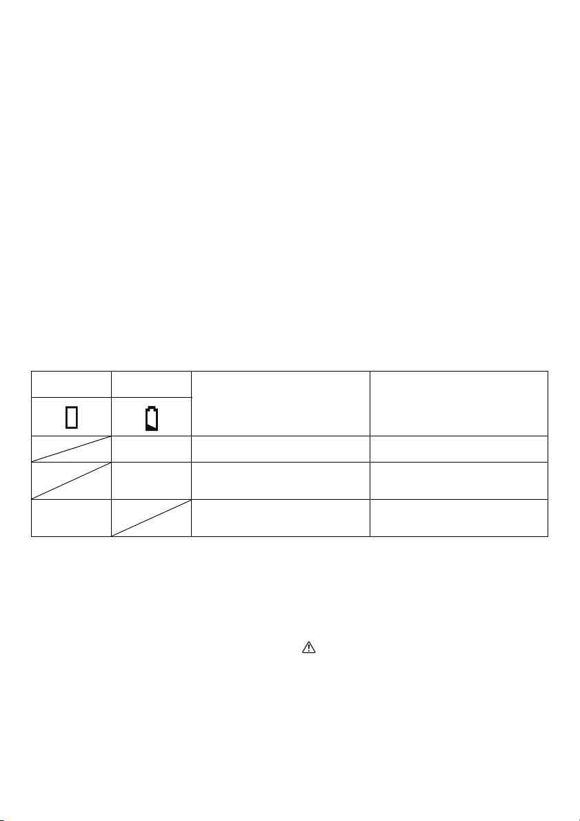
Power indicator Battery indicator
Status Action to be taken
Blinking
Lighting up
Blinking
013900
Battery power has been nearly used
up.
Battery protector is shutting off the
power - battery power has been used
up.
Overheat protector is shutting off the
power - overheating.
Nylon cutting head
NOTICE:
• Do not attempt to bump feed the head while the tool is
operating at a high RPM. Bump feeding at a high RPM
may cause damage to the nylon cutting head.
• The bump feed will not operate properly if the head is
not rotating. (Fig. 12)
The nylon cutting head is a dual grass trimmer head
provided with a bump & feed mechanism.
To cause the nylon cord to feed out, the cutting head
should be bumped against the ground while rotating at a
low RPM.
NOTE:
If the nylon cord does not feed out while bumping the
head, rewind/replace the nylon cord by following the
procedures described under “Maintenance”.
ASSEMBLY
WARNING:
• Always be sure that the tool is switched off and
battery cartridge is removed before carrying out
any work on the tool. Failure to switch off and remove
the battery cartridge may result in serious personal
injury from accidental start-up.
• Never start the tool unless it is completely
assembled. Operation of the tool in a partially
assembled state may result in serious personal injury
from accidental start-up.
Mounting the attachment pipe
Only for model DUR143U, DUR183U (Fig. 13)
To mount the attachment to a power unit:
1. Make sure that the lever is not tightened.
2. To open the entrance of the joint, depress the joint
cover. (Fig. 14)
3. Align the protrusion on the pipe (cutting tool side ) with
the concave portion of the joint part.
4. Insert the attachment pipe into the joint part. Make
sure that the surface of the lock lever is horizontal to
the pipe.
5. Tighten the lever firmly as shown.
To remove the attachment, loosen the lever, press the
front part of the lock lever and then slide the pipe.
Replace the battery with fully charged
one.
Replace the battery with fully charged
one.
Rest and cool down the equipment for
a while.
Installing the handles
To allow power switch action by right hand, place the
handle with the switch trigger to the right side of the tool.
Place the other side handle to the left side of the tool.
(Fig. 15 & 16)
Set both tops of the handles in the groove in the handle
holder, cover the handles by the handle clamp and then
secure it slightly by the hex bolts.
Adjust the handle to an angle that provides a comfortable
working position and then secure by firmly hex bolts.
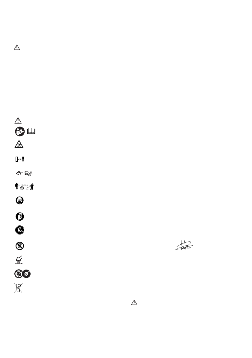
Installing the guard
WARNING:
• Never use the tool without the guard illustrated in
place. Failure to do so can cause serious personal
injury. (Fig. 17 & 18)
Align the protrusions on the protector with the grooves of
the motor housing. (Fig. 19)
Align the protrusions on the protector holder with the
concave portions of the motor housing. Insert the
protector holder to the motor housing. (Fig. 20)
After attaching the protector and the protector holder to
the motor housing, tighten the hex bolts securely.
Installing the wire guard
CAUTION:
• Before adjusting the wire guard, wait for the cutting
head comes to standstill. Do not adjust the wire guard
with your foot. (Fig. 21)
To reduce the risk damaging the objects in front of the
cutting head, insert the wire guard so that it controls the
cutting range of the mowing line. (Fig. 22)
Slightly expand the wire guard outward and then insert it
into the holes of the protector.
NOTE:
• Do not expand the wire guard outward too much.
Otherwise it may break. (Fig. 23)
When wire guard is not in use, lift it for the idle position.
Installing nylon cutting head
NOTICE:
• Be sure to use genuine Makita nylon cutting head.
Turn the tool upside down so that you can replace the
nylon cutting head easily. (Fig. 24)
Insert the hex wrench through the hole on the protector
cover and the motor housing and rotate the receive
washer until it is locked with the hex wrench. Mount the
13

metal guard, the nylon cutting head onto the threaded
spindle directly and tighten it by turning it
counterclockwise. Remove the hex wrench.
To remove the nylon cutting head, turn the nylon cutting
head clockwise while holding the receive washer with the
hex wrench.
CAUTION:
• If during operation the nylon cutting head
accidentally impacts a rock or hard object the
trimmer should be stopped and inspected for any
damage. If the nylon cutting head is damaged it
should be replaced immediately. Use of a damaged
nylon cutting head could result in serious personal
injury.
OPERATION
Correct handling of tool
Attachment of shoulder harness (Fig. 25)
Put the shoulder harness on. Then connect the buckles
on both the hook and the harness. Be sure that the
buckles click and lock completely in place.
Only for model DUR143U, DUR183U (Fig. 26)
When the cap is not in use, hang it on the hook.
Detachment (Fig. 27)
The buckle is provided with a means of quick release.
Simply squeeze the sides and the buckle to release the
tool.
WARNING:
• Be extremely careful to maintain control of the tool
at all times. Do not allow the tool to be deflected
toward you or anyone in the work vicinity. Failure to
keep control of the tool could result in serious injury to
the bystander and the operator.
Adjustment of the hanger position and shoulder
harness (Fig. 28)
To change the hanger position, loosen the hex bolt on the
hanger with the supplied wrench. Then move the hanger
and cushion.
After adjusting the hanger position, tighten the hex bolt
with the wrench securely.
the nylon cutting head to fly apart resulting in serious
personal injury. (Fig. 29)
Take off cover from housing, pressing two latches which
are slotted section oppositely on side of housing. (Fig. 30)
Cut a nylon line in 3-6 m. Fold the cutting line in two
halves, leave one of half longer 80-100 mm than another.
(Fig. 31)
Hook the middle of the new nylon cord to the notch
located at the center of the spool between the 2 channels
provided for the nylon cord.
Wind both ends firmly around the spool in the direction
marked on the head for left hand direction indicated by
LH. (Fig. 32)
Wind all but about 100 mm of the cords, leaving the ends
temporarily hooked through a notch on the side of the
spool. (Fig. 33)
Mount the spool on the cover so that the grooves and
protrusions on the spool match up with those on the
cover. Now, unhook the ends of the cord from their
temporary position and feed the cords through the eyelets
to come out of the cover. (Fig. 34)
Align the protrusion on the underside of the cover with the
slots of the eyelets. Then push the cover firmly onto the
housing to secure it. Make sure the latches fully spread in
the cover.
To maintain product SAFETY and RELIABILITY, repairs,
any other maintenance or adjustment should be
performed by Makita Authorized Service Centers, always
using Makita replacement parts.
TROUBLE SHOOTING
Before asking for repairs, conduct your own inspection
first. If you find a problem that is not explained in the
manual, do not attempt to dismantle the tool. Instead, ask
Makita Authorized Service Centers, always using Makita
replacement parts for repairs.
MAINTENANCE
WARNING:
• Always be sure that the tool is switched off and
battery cartridge is removed before attempting to
perform inspection or maintenance on the tool.
Failure to switch off and remove the battery cartridge
may result in serious personal injury from accidental
start-up.
NOTICE:
Never use gasoline, benzine, thinner, alcohol or the
like. Discoloration, deformation or cracks may result.
Replacing the nylon cord
WARNING:
• Make sure that the cover of the nylon cutting head
is secured to the housing properly as described
below. Failure to properly secure the cover may cause
14

Malfunction status Cause Action
Motor does not run.
Motor stops running after a little use.
It does not reach maximum RPM.
Cutting tool does not rotate:
Stop the machine immediately!
Abnormal vibration:
Stop the machine immediately!
Cutting tool and motor cannot stop:
Remove the battery immediately!
010856
Battery cartridge is not installed. Install the battery cartridge.
Battery problem (under voltage)
The drive system does not work
correctly.
Rotation is in reverse.
Battery’s charge level is low.
Overheating.
Battery is installed improperly.
Battery power is dropping.
The drive system does not work
correctly.
Foreign object such as a branch is
jammed between the guard and the
nylon cutting head.
The drive system does not work
correctly.
One end of the nylon cord has been
broken.
The drive system does not work
correctly.
Electric or electronic malfunction.
Recharge the battery. If recharging is
not effective, replace battery.
Ask your local authorized service
center for repair.
Change the direction of ratation with
the reversing switch.
Recharge the battery. If recharging is
not effective, replace battery.
Stop using of tool to allow it to cool
down.
Install the battery cartridge as
described in this manual.
Recharge the battery. If recharging is
not effective, replace battery.
Ask your local authorized service
center for repair.
Remove the foreign object.
Ask your local authorized service
center for repair.
Bump the nylon cutting head against
the ground while it is rotating to cause
the cord to feed.
Ask your local authorized service
center for repair.
Remove the battery and ask your local
authorized service center for repair.
OPTIONAL ACCESSORIES
CAUTION:
• These accessories or attachments are recommended
for use with your Makita tool specified in this manual.
The use of any other accessories or attachments might
present a risk of injury to persons. Only use accessory
or attachment for its stated purpose.
If you need any assistance for more details regarding
these accessories, ask your local Makita Service Center.
• Nylon cutting head
• Nylon cord (cutting line)
• Shoulder harness
•Hex wrench
• Makita genuine battery and charger
NOTE:
• Some items in the list may be included in the tool
package as standard accessories. They may differ
from country to country.
15

FRANÇAIS (Instructions d’origine)
Descriptif
1. Batterie
2. Voyant
3. Crochet (point de suspension)
4. Gâchette
5. Poignée
6. Protège-lame
7. Protège-fil
8. Outil de coupe
9. Molette de réglage de la vitesse
10. Bouton d’alimentation
11. Bandoulière
12. Coiffe
13. Voyant rouge
14. Bouton
15. Voyant d’alimentation
16. Bouton de sécurité
17. Inverseur
18. Position A pour le fonctionnement
normal
19. Position B pour le retrait des
mauvaises herbes et des débris
20. Étoile
21. Indicateur de batterie
22. Zone de coupe la plus efficace
23. Joint
24. Levier de verrouillage
25. Couvre-joint
26. Levier
27. Tuyau (du côté de l’outil de coupe)
28. Partie concave
29. Partie saillante
30. Dispositif de serrage de la poignée
31. Rainure
32. Support de poignée
33. Poignée
34. Boulon hexagonal
35. Rainures
36. Dispositif de protection
37. Parties concaves
38. Support de protection
39. Parties saillantes
40. Boulons hexagonaux
41. Orifices
42. Tête à fil de nylon
43. Dispositif de protection métallique
44. Rondelle de réception
45. Clé hexagonale
46. Boucle
47. Crochet
48. Support en caoutchouc
49. 80-100 mm
SPÉCIFICATIONS
Modèle DUR142U DUR143U DUR182U DUR183U
Type de tuyau Tuyau intégré Tuyau divisible Tuyau intégré Tuyau divisible
Vitesse à vide 3 500 - 6 000 min
1 843 mm
967 mm
Longueur totale
Diamètre de coupe avec la tête à fil de
nylon
—
(Côté outil de
coupe, coiffe
incluse)
982 mm
(Côté batterie)
300 mm
Poids net 4,0 kg 4,2 kg 4,1 kg 4,3 kg
Tension nominale 14,4 V C.C. 18 V C.C.
Batterie standard et chargeur
Associez toujours les batteries et
chargeurs comme indiqué dans les
BL1430, BL1440/DC18RC BL1830, BL1840/DC18RC
colonnes de droite.
• Étant donné l’évolution constante de notre programme de recherche et de développement, les spécifications
contenues dans ce manuel sont sujettes à des modifications sans préavis.
• Les spécifications et la batterie peuvent varier d’un pays à l’autre.
• Poids, batterie incluse, selon la procédure EPTA 01/2003
Bruit Niveau de pression sonore
Modèle L
(dB (A)) Incertitude K (dB (A))
PA
DUR142U/DUR143U 78 1,0
DUR182U/DUR183U 79 0,7
• Même si le niveau de pression sonore indiqué ci-dessus est de 80 dB (A) ou moins, le niveau en fonctionnement peut
dépasser 80 dB (A). Portez des protections auditives.
Vibrations Main gauche Main droite
Modèle a
(m/s2)
h
Incertitude K
2
)
(m/s
a
h
(m/s2)
DUR142U/DUR143U 2,5 1,5 2,5 1,5
DUR182U/DUR183U 2,5 1,5 2,5 1,5
-1
—
Norme ou directive applicable
2000/14/CE
Incertitude K
2
(m/s
Norme ou directive
)
967 mm
(Côté outil de
coupe, coiffe
incluse)
982 mm
(Côté batterie)
applicable
EN786
16
• La valeur de l’émission des vibrations déclarée a été
Cd
Ni-MH
Li-ion
ENG901-1
mesurée conformément à la méthode de test standard
et peut être utilisée afin de comparer des outils entre
eux.
• La valeur de l’émission des vibrations déclarée peut
également être utilisée lors d’une évaluation
préliminaire de l’exposition.
AVERTISSEMENT :
• Selon la manière dont l’outil est utilisé, il est possible
que l’émission des vibrations pendant l’utilisation réelle
de l’outil électrique diffère de la valeur de l’émission
déclarée.
• Veillez à identifier les mesures de sécurité destinées à
protéger l’opérateur et établies en fonction de
l’estimation de l’exposition dans les conditions réelles
d’utilisation (en prenant en compte toutes les étapes du
cycle de fonctionnement, telles que les périodes de
mise hors tension de l’outil, les périodes de
fonctionnement au ralenti et les périodes de mise en
route).
Symboles
END020-3
Les symboles utilisés pour l’appareil sont indiqués cidessous. Assurez-vous d’avoir bien compris leur
signification avant d’utiliser l’appareil.
.................... Usez d’attention et de soins
particuliers.
........ Reportez-vous au manuel
d’instructions.
.................. Danger ; méfiez-vous du risque de
projection d’objets.
.................. La distance entre l’appareil et les
spectateurs doit être d’au moins 15 m.
.......... Éloignez les spectateurs.
.......... Tenez-les à une distance d’au moins
15 m.
.................. Portez un casque protecteur, des
lunettes de sécurité et des protections
d’oreilles.
.................. Portez des gants de protection.
.................. Portez des bottes de sécurité avec des
semelles antidérapantes. Les bottes de
sécurité munies d’une coquille en acier
sont recommandées.
.................. Tenez l’appareil à l’abri de l’humidité.
.............Pour les pays européens uniquement
Ne pas jeter les appareils électriques et
les bloc-batteries dans les ordures
ménagères !
Conformément aux directives
européennes relatives aux déchets
d’équipements électriques ou
électroniques (DEEE) ainsi qu’aux
batteries, aux accumulateurs et aux
batteries et accumulateurs usagés et à
leur transposition dans la législation
nationale, les appareils électriques, les
batteries et les bloc-batteries doivent
être collectés à part et être soumis à un
recyclage respectueux de
l’environnement.
Pour les pays d’Europe uniquement
ENH219-2
Déclaration de conformité CE
Nous, Makita Corporation, en tant que fabricant
responsable, déclarons que la ou les machines
Makita suivantes :
Nom de la machine :
Coupe Herbe Sans Fil
N° de modèle/Type : DUR142U, DUR143U,
DUR182U, DUR183U
Spécifications : voir le tableau
« SPÉCIFICATIONS ».
sont fabriquées en série et
sont conformes aux directives européennes
suivantes :
2000/14/CE, 2006/42/CE
et sont produites conformément aux normes ou
documents de normalisation suivants :
EN60335
La documentation technique est disponible auprès de :
Makita International Europe Ltd.
Technical Department,
Michigan Drive, Tongwell,
Milton Keynes, Bucks MK15 8JD, Angleterre
La procédure d’évaluation de la conformité requise par la
directive 2000/14/CE est conforme à l’annexe VI.
Organisme notifié :
TÜV Rheinland LGA Products GmbH
Tillystraße 2
90431 Nürnberg, Allemagne
Numéro d’identification 0197
Modèle DUR142U, DUR143U
Niveau de puissance sonore mesurée : 89 dB (A)
Niveau de puissance sonore garantie : 90 dB (A)
Modèle DUR182U, DUR183U
Niveau de puissance sonore mesurée : 90 dB (A)
Niveau de puissance sonore garantie : 90 dB (A)
5. 3. 2013
................... Vitesse maximale autorisée pour l’outil.
............ N’utilisez jamais de lame en métal.
Tomoyasu Kato
Directeur
Makita Corporation
3-11-8, Sumiyoshi-cho,
Anjo, Aichi, 446-8502, JAPAN
17

CONSIGNES DE SÉCURITÉ
IMPORTANTES
AVERTISSEMENT ! Veuillez lire toutes les
consignes de sécurité et les instructions. Le non-
respect des consignes et instructions peut entraîner un
choc électrique, un incendie et/ou des blessures graves.
Conservez toutes les consignes et
instructions pour référence ultérieure.
1. Familiarisez-vous avec les commandes et
l’utilisation correcte du matériel.
2. Les éléments coupants continuent à tourner après
l’arrêt du moteur.
3. Ne laissez pas des enfants ou des personnes ne
connaissant pas ces instructions utiliser
l’appareil.
4. Cessez d’utiliser l’appareil lorsque des personnes,
notamment des enfants, ou des animaux
domestiques se trouvent à proximité.
5. Utilisez l’appareil uniquement en journée ou sous
une lumière artificielle correcte.
6. Avant d’utiliser l’appareil et après tout impact,
recherchez d’éventuels signes d’usure ou de
dommage et réparez-les au besoin.
7. Veillez à ne pas vous blesser sur les dispositifs
installés pour couper la longueur du fil. Après
avoir sorti un nouveau fil de coupe, replacez
toujours l’appareil en position de fonctionnement
normal avant de le mettre sous tension.
8. N’installez jamais d’éléments de coupe en métal.
9. Cet appareil ne doit pas être utilisé par des
personnes (notamment des enfants) dont les
capacités physiques, sensorielles ou mentales
sont réduites ou n’ayant aucune expérience ni
compétence, à moins d’avoir reçu des
instructions relatives à l’utilisation de l’appareil
par une personne responsable de leur sécurité ou
d’être sous la supervision de celle-ci. Les enfants
doivent être surveillés car ils ne doivent pas jouer
avec l’appareil.
10. Utilisez l’outil avec une précaution et une attention
extrêmes.
11. Utilisez l’outil uniquement si vous êtes en bonne
condition physique. Effectuez tout le travail avec
calme et prudence. Faites preuve de bon sens et
gardez à l’esprit que l’opérateur ou l’utilisateur est
responsable des accidents ou blessures infligés à
d’autres personnes ou à leurs biens.
12. N’utilisez jamais l’outil lorsque vous êtes
fatigué(e), malade ou sous l’emprise de l’alcool ou
de médicaments.
13. Vous devez immédiatement mettre l’outil hors
tension si vous observez des signes de
dysfonctionnement.
Utilisation prévue de l’outil
1. Utilisez le bon outil. Le coupe-herbe sans fil doit
être utilisé exclusivement pour couper l’herbe et
les mauvaises herbes de petite taille. Il n’est
conçu pour aucune autre utilisation, telle que la
coupe des haies, car cela comporte un risque de
blessure.
GEB109-3
Équipement de protection corporelle (Fig. 1 et 2)
1. Portez des vêtements adéquats. Les vêtements
que vous portez doivent être fonctionnels et
appropriés, c’est-à-dire qu’ils doivent être près du
corps, sans pour autant gêner vos mouvements.
Ne portez pas de bijoux ou de vêtements
susceptibles d’être happés par l’appareil. Portez
un filet de protection pour envelopper vos
cheveux s’ils sont longs.
2. Lorsque vous utilisez l’outil, portez toujours des
chaussures de sécurité munies d’une semelle
antidérapante. Elles vous protègeront de
blessures éventuelles et vous assureront une
bonne stabilité.
3. Portez des lunettes ou un masque de protection.
Sécurité électrique et de la batterie
1. Évitez les environnements dangereux. N’utilisez
pas l’outil dans des lieux humides et ne l’exposez
pas aux intempéries. Le risque de choc électrique
augmente lorsque de l’eau pénètre dans l’outil.
2. N’utilisez que le chargeur spécifié par le fabricant.
Un chargeur adapté à un type de batterie peut
créer un risque d’incendie s’il est utilisé avec un
autre type de batterie.
3. Utilisez les outils électriques uniquement avec les
batteries indiquées. L’utilisation d’autres types de
batterie peut créer un risque de blessures et
d’incendie.
4. Lorsque vous n’utilisez pas la batterie, gardez-la
éloignée de tout objet métallique, comme les
trombones, pièces, clefs, clous, vis ou autres
petits objets métalliques, qui peuvent faire office
de connexion d’une borne à l’autre. Court-circuiter
les bornes de la batterie peut provoquer des
brûlures ou un incendie.
5. En cas de mauvaise utilisation, du liquide peut fuir de
la batterie ; évitez tout contact. En cas de contact
accidentel, nettoyez la surface en question à l’eau. Si
le liquide entre en contact avec les yeux, consultez un
médecin. Le liquide émis par la batterie peut
provoquer une irritation ou des brûlures.
6. Ne jetez pas les batteries au feu. Elles risqueraient
d’exploser. Consultez la réglementation locale
pour connaître les éventuelles consignes de mise
au rebut spéciales.
7. N’ouvrez pas les batteries et n’essayez pas de les
démonter. L’électrolyte libéré est corrosif et
risquerait de blesser vos yeux ou votre peau. Si
vous l’avalez, il peut se révéler toxique.
Démarrage de l’outil (Fig. 3)
1. Éloignez les personnes et les enfants du lieu de
travail à une distance minimum de 15 mètres et
faites attention aux animaux qui pourraient se
trouver à proximité. Le cas échéant, cessez
d’utiliser l’outil.
2. Avant l’utilisation, vérifiez toujours que l’outil ne
présente aucun danger. Vérifiez la sécurité de
l’outil de coupe et de son protège-lame, ainsi que
le fonctionnement de la gâchette et du levier.
Vérifiez que les poignées sont propres et sèches
et testez le fonctionnement de l’interrupteur.
3. Recherchez les éventuelles pièces endommagées
avant de continuer à utiliser l’outil. Un protège-
18

lame ou une autre pièce endommagé(e) doit être
inspecté(e) soigneusement pour déterminer s’il/si
elle va fonctionner correctement. Assurez-vous
que les pièces en mouvement sont alignées et se
déplacent librement, qu’aucune pièce n’est
cassée, que les pièces sont correctement
montées et qu’aucune anomalie ne risque
d’affecter le fonctionnement de l’appareil. Un
protège-lame ou toute autre pièce endommagé(e)
doit être correctement réparé(e) ou remplacé(e)
par un centre de service agréé, sauf indication
contraire dans ce manuel.
4. Ne mettez le moteur sous tension que lorsque vos
mains et vos pieds sont éloignés de l’outil de
coupe.
5. Avant de commencer, assurez-vous que l’outil de
coupe n’est pas en contact avec des objets durs
tels que des branches, des pierres, etc. car il
tournera au démarrage.
Mode d’emploi
1. N’utilisez jamais l’appareil si les protège-lames
sont endommagés ou s’ils ne sont pas en place.
2. N’utilisez l’outil que dans des conditions
d’éclairage et de luminosité suffisantes. En hiver,
soyez attentif aux zones glissantes ou mouillées,
au verglas et à la neige (risque de glissade).
Assurez-vous toujours d’avoir une bonne stabilité.
3. Faites attention à ne pas vous blesser les pieds et
les mains avec l’outil de coupe.
4. Maintenez constamment vos mains et vos pieds
éloignés de la coupe, en particulier lors de la mise
sous tension du moteur.
5. Ne coupez jamais à une hauteur supérieure aux
épaules.
6. N’utilisez jamais l’outil sur une échelle.
7. Ne travaillez jamais sur des surfaces instables.
8. Ne vous penchez pas. Conservez une bonne prise
au sol et restez constamment en équilibre.
9. Enlevez le sable, les pierres, les clous etc.,
trouvés à l’intérieur du périmètre de travail. Des
particules étrangères peuvent endommager l’outil
de coupe ou être projetées et entraîner des
dommages corporels.
10. Si l’outil de coupe heurte des pierres ou d’autres
objets durs, éteignez immédiatement le moteur et
examinez l’outil de coupe.
11. Avant de commencer à couper, l’outil de coupe
doit avoir atteint sa vitesse de travail maximale.
12. Tenez toujours l’outil à deux mains. Ne le tenez
jamais d’une seule main durant l’utilisation.
Assurez-vous toujours d’avoir une bonne stabilité.
13. Tous les équipements de protection fournis avec
l’outil, tels que le protège-lame et le protège-fil,
doivent être utilisés pendant le fonctionnement.
14. Sauf en cas d’urgence, ne laissez jamais tomber
l’outil et ne le jetez pas sur le sol, cela risquerait
de l’endommager grièvement.
15. Ne traînez jamais l’outil sur le sol lorsque vous le
déplacez, cela pourrait l’endommager.
16. Retirez toujours la batterie de l’outil :
- toutes les fois où l’outil doit être laissé sans
surveillance ;
- avant toute opération de retrait d’obstruction ;
- avant toute opération de vérification,
nettoyage ou réparation de l’outil ;
- avant d’effectuer des réglages, de changer des
accessoires ou de ranger l’appareil ;
- dès que l’outil commence à vibrer de manière
anormale ;
- lors du transport de l’outil.
17. N’utilisez pas l’appareil au-dessus des capacités
pour lesquels il a été conçu. Cela pourrait nuire à
la qualité du travail et provoquer un risque de
blessures.
Instructions d’entretien
1. Vous devez vérifier l’état de l’outil de coupe, des
protections et de la bandoulière avant chaque
utilisation.
2. Avant d’effectuer une opération d’entretien, de
remplacer l’outil de coupe ou de nettoyer l’outil,
mettez le moteur hors tension et retirez la batterie.
3. Après utilisation, débranchez la batterie de l’outil
et vérifiez qu’elle n’est pas endommagée.
4. Vérifiez que les dispositifs de fixation sont bien
attachés et recherchez les éventuelles pièces
endommagées, comme des fissures sur l’outil de
coupe.
5. Lorsque vous ne l’utilisez pas, rangez l’appareil
dans un endroit sec fermé à clé ou hors de portée
des enfants.
6. N’utilisez que les pièces et accessoires de
remplacement recommandés par le fabricant.
7. Assurez-vous toujours que les ouvertures de
ventilation ne sont pas obstruées par des débris.
8. Inspectez et assurez régulièrement l’entretien de
l’outil, particulièrement avant/après utilisation. Ne
faites réparer l’outil que par notre centre de
service agréé.
9. Maintenez les poignées de l’outil sèches, propres
et exemptes d’huile ou de graisse.
CONSERVEZ CES
INSTRUCTIONS.
AVERTISSEMENT :
NE vous laissez PAS tromper (au fil d’une utilisation
répétée) par un sentiment d’aisance et de familiarité
avec le produit, en négligeant le respect rigoureux
des consignes de sécurité qui accompagnent l’outil.
Une UTILISATION INCORRECTE de l’outil ou le nonrespect des consignes de sécurité indiquées dans ce
manuel d’instructions peuvent causer des blessures
graves.
CONSIGNES DE SÉCURITÉ
IMPORTANTES ENC007-8
POUR LA BATTERIE
1. Avant d’utiliser la batterie, veuillez lire toutes les
instructions et tous les avertissements inscrits
sur (1) le chargeur, (2) la batterie et (3) l’appareil
alimenté par la batterie.
2. Ne démontez pas la batterie.
3. Cessez immédiatement d’utiliser l’outil si le temps
de fonctionnement devient excessivement court. Il
19

y a risque de surchauffe, de brûlures, voire
d’explosion.
4. Si l’électrolyte pénètre dans vos yeux, rincez-les à
l’eau claire et consultez immédiatement un
médecin. Il y a risque de perte de la vue.
5. Évitez de court-circuiter la batterie :
(1) Ne touchez les bornes avec aucun matériau
conducteur.
(2) Évitez de ranger la batterie dans un
contenant où se trouvent d’autres objets
métalliques tels que des clous, pièces de
monnaie, etc.
(3) N’exposez pas la batterie à l’eau ou à la pluie.
Un court-circuit de la batterie risque de provoquer
un fort courant, une surchauffe, parfois des
brûlures et même une panne.
6. Ne rangez pas l’outil ou la batterie dans des
endroits où la température risque d’atteindre ou
de dépasser 50°C (122°F).
7. Ne jetez pas la batterie au feu même si elle est
sérieusement endommagée ou complètement
épuisée. La batterie peut exploser au contact du
feu.
8. Veillez à ne pas laisser tomber ou heurter la
batterie.
9. N’utilisez pas de batterie endommagée.
10. Respectez les réglementations locales relatives à
la mise au rebut des batteries.
CONSERVEZ CES
INSTRUCTIONS.
Conseils pour assurer la durée de vie
optimale de la batterie
1. Rechargez la batterie avant qu’elle ne soit
complètement épuisée.
Arrêtez toujours l’outil et rechargez la batterie
quand vous constatez que la puissance de l’outil
diminue.
2. Ne rechargez jamais une batterie complètement
chargée.
La surcharge réduit la durée de service de la
batterie.
3. Chargez la batterie alors que la température de la
pièce se trouve entre 10°C et 40°C (50°F et 104°F).
Si une batterie est chaude, laissez-la refroidir
avant de la charger.
4. Si vous n’utilisez pas l’outil pendant une période
prolongée, rechargez la batterie tous les six mois.
Installation et retrait de la batterie (Fig. 5)
ATTENTION :
• Éteignez toujours l’outil avant d’installer ou de déposer
la batterie.
• Tenez fermement l’outil et la batterie lors de
l’installation ou du retrait de la batterie. Si vous ne
tenez pas fermement l’outil et la batterie, ils risquent de
glisser et de s’abîmer ou de vous blesser.
Pour retirer la batterie, faites glisser le bouton à l’avant de
la batterie et sortez la batterie.
Pour installer la batterie, alignez sa languette sur la
rainure qui se trouve à l’intérieur du capot, puis glissez la
batterie pour la mettre en place. Insérez-la bien à fond,
jusqu’à ce qu’elle se verrouille en émettant un léger clic.
Si vous pouvez voir le voyant rouge sur la face supérieure
du bouton, la batterie n’est pas parfaitement verrouillée.
ATTENTION :
• Installez toujours la batterie à fond, de sorte que le
voyant rouge ne soit plus visible. Sinon, elle risque de
tomber accidentellement de l’outil, en vous blessant ou
en blessant une personne située près de vous.
• Ne forcez pas pour installer la batterie. Si la batterie ne
glisse pas aisément, c’est qu’elle n’est pas insérée
correctement.
Fonctionnement de l’interrupteur
AVERTISSEMENT :
• Avant d’insérer la batterie dans l’outil, vérifiez
toujours que la gâchette fonctionne bien et revient
en position d’arrêt lorsqu’elle est relâchée.
N’appuyez pas fortement sur la gâchette sans avoir
d’abord enfoncé le bouton de sécurité. Vous
risqueriez de casser l’interrupteur. Si vous faites
fonctionner un outil dont l’interrupteur est défectueux,
vous risquez d’en perdre le contrôle et de vous blesser
grièvement. (Fig. 6)
Appuyez sur le bouton d’alimentation sur le capot afin que
l’outil soit mis sous tension et que le voyant d’alimentation
s’allume. (Fig. 7)
Pour éviter tout déclenchement accidentel de la gâchette,
l’outil est muni d’un bouton de sécurité.
Pour démarrer l’outil, enfoncez le bouton de sécurité puis
appuyez sur la gâchette. Pour l’arrêter, relâchez la
gâchette.
REMARQUE :
• Si l’outil ne fonctionne pas pendant une minute alors
que le bouton d’alimentation est enfoncé, il est
automatiquement mis hors tension.
Description des pièces (Fig. 4)
DESCRIPTION DU
FONCTIONNEMENT
AVERTISSEMENT :
• Veillez toujours à ce que l’outil soit éteint et la
batterie déposée avant d’effectuer des réglages ou
de vérifier le fonctionnement de l’outil. Si vous ne
mettez pas l’outil hors tension et ne retirez pas la
batterie, vous risquez de vous blesser grièvement en
cas de démarrage accidentel.
20
Inverseur pour le retrait des débris
AVERTISSEMENT :
• Veillez toujours à ce que l’outil soit éteint et la
batterie déposée avant de retirer les mauvaises
herbes et débris qui n’ont pas pu être retirés en
mode inversé. Si vous ne mettez pas l’outil hors
tension et ne retirez pas la batterie, vous risquez de
vous blesser grièvement en cas de démarrage
accidentel. (Fig. 8)
Cet outil dispose d’un inverseur qui permet de changer le
sens de rotation afin de retirer les mauvaises herbes et
les débris coincés dans l’outil. Pour faire fonctionner l’outil
normalement, l’interrupteur doit être basculé sur la
position A.
Pour retirer les mauvaises herbes et débris coincés dans
la tête de rotation, vous pouvez inverser l’outil en
basculant l’interrupteur sur la position B. En position
inversée, l’outil ne fonctionne que brièvement avant de
s’éteindre automatiquement.
NOTE :
• Vérifiez toujours le sens de rotation avant de mettre
l’outil en marche.
• N’actionnez l’inverseur qu’une fois l’outil complètement
arrêté. Si vous changez le sens de rotation de l’outil
avant l’arrêt de celui-ci, vous risquez de l’endommager.
Molette de réglage de la vitesse (Fig. 9)
La vitesse de l’outil peut être réglée en continu de
3500min
la vitesse.
Tournez la molette de réglage de la vitesse dans le sens
des aiguilles d’une montre pour augmenter la vitesse, et
en sens inverse pour la réduire.
-1
à 6 000 min-1 grâce à la molette de réglage de
Système de protection de la batterie
(batterie au lithium-ion comportant une
étoile) (Fig. 10)
Les batteries au lithium-ion comportant une étoile sont
équipées d’un système de protection. Ce système coupe
Voyant
d’alimentation
Indicateur de
batterie
automatiquement l’alimentation en électricité vers l’outil
afin de prolonger sa durée de vie.
L’outil s’arrête automatiquement pendant le
fonctionnement lorsqu’il et/ou la batterie se trouvent dans
l’une des situations suivantes :
• En surcharge :
L’outil fonctionne de manière à créer un courant
anormalement élevé.
Dans ce cas, relâchez la gâchette de l’outil et arrêtez
l’application qui cause la surcharge de l’outil. Ensuite,
appuyez à nouveau sur la gâchette pour redémarrer
l’outil.
Si l’outil ne démarre pas, la batterie est en
surchauffe. Dans ce cas, laissez la batterie refroidir
avant de presser à nouveau la gâchette.
• Faible tension de la batterie :
L’autonomie restante est trop basse et l’outil ne
fonctionnera pas. Dans ce cas, retirez la batterie et
rechargez-la.
Voyants (Fig. 11)
Lorsque le système de protection est activé pendant le
fonctionnement de l’outil, les voyants s’allument.
Reportez-vous au tableau suivant pour connaître l’état de
la batterie et les mesures à prendre concernant le voyant.
État Mesure à prendre
Clignotant La batterie est presque déchargée.
Allumé
Clignotant
013900
Le dispositif de protection de la batterie
met l’appareil hors tension : la batterie
est déchargée.
Le dispositif de protection contre les
surchauffes met l’appareil hors tension
en raison d’une surchauffe.
Tête à fil de nylon
NOTE :
• Ne tentez pas de procéder à l’alimentation semiautomatique par frappe au sol lorsque l’outil fonctionne
à un régime élevé. L’alimentation semi-automatique
par frappe au sol à un régime élevé peut endommager
la tête à fil de nylon.
• L’alimentation semi-automatique par frappe au sol ne
fonctionnera pas correctement si la tête ne tourne pas.
(Fig. 12)
La tête à fil de nylon est une tête de coupe-herbe double
équipée d’un mécanisme d’alimentation semiautomatique par frappe au sol.
Pour faire sortir le fil de nylon, la tête à fil de nylon doit
être frappée contre le sol tout en tournant à bas régime.
Remplacez la batterie par une batterie
rechargée.
Remplacez la batterie par une batterie
rechargée.
Posez l’appareil et laissez-le refroidir
un moment.
REMARQUE :
Si le fil de nylon ne sort pas lorsque vous frappez la tête,
rembobinez/remplacez le fil en suivant les procédures
décrites dans la section « Entretien ».
MONTAGE
AVERTISSEMENT :
• Assurez-vous toujours que l’outil est hors tension
et la batterie déposée avant d’effectuer toute
intervention sur l’outil. Si vous ne mettez pas l’outil
hors tension et ne retirez pas la batterie, vous risquez
de vous blesser grièvement en cas de démarrage
accidentel.
• Ne démarrez jamais l’outil avant qu’il soit
complètement assemblé. Si vous le faites fonctionner
alors qu’il n’est pas parfaitement assemblé, vous
risquez de vous blesser grièvement en cas de
démarrage accidentel.
21

Montage du tuyau de fixation
Uniquement pour le modèle DUR143U, DUR183U
(Fig. 13)
Pour fixer l’accessoire au groupe moteur :
1. Assurez-vous que le levier n’est pas serré.
2. Pour ouvrir l’entrée du joint, appuyez sur le couvre-
joint. (Fig. 14)
3. Alignez la partie saillante sur le tuyau (du côté de
l’outil de coupe) sur la partie concave du joint.
4. Insérez le tuyau de fixation dans le joint. Assurez-vous
que la surface du levier de verrouillage est horizontale
par rapport au tuyau.
5. Serrez solidement le levier comme illustré.
Pour retirer la fixation, desserrez le levier, appuyez sur la
partie avant du levier de verrouillage, puis faites glisser le
tuyau.
Installation des poignées
Pour pouvoir utiliser l’interrupteur avec la main droite,
placez la poignée avec la gâchette sur le côté droit de
l’outil. Placez l’autre poignée sur le côté gauche de l’outil.
(Fig. 15 et 16)
Placez les deux parties supérieures des poignées dans la
rainure du support de poignée, recouvrez les poignées
avec le dispositif de serrage de la poignée, puis serrez-le
légèrement à l’aide des boulons hexagonaux.
Réglez la poignée selon un angle qui offre une position de
travail confortable, puis serrez-la fermement à l’aide des
boulons hexagonaux.
Installation du protège-lame
AVERTISSEMENT :
• N’utilisez jamais l’outil si le protège-lame illustré ci-
dessus n’est pas en place. Dans le cas contraire, il y
a risque de blessure corporelle grave. (Fig. 17 et 18)
Alignez les parties saillantes sur le dispositif de protection
avec les rainures du capot du moteur. (Fig. 19)
Alignez les parties saillantes sur le support de protection
avec les parties concaves du capot du moteur. Insérez le
support de protection sur le capot du moteur. (Fig. 20)
Après avoir fixé le dispositif de protection et le support de
protection sur le capot du moteur, serrez fermement les
boulons hexagonaux.
Installation du protège-fil
ATTENTION :
• Avant de régler le protège-fil, attendez que la tête de
coupe soit immobile. Ne réglez pas le protège-fil avec
votre pied. (Fig. 21)
Pour réduire le risque d’endommagement des objets face
à la tête de coupe, insérez le protège-fil de sorte qu’il
contrôle la plage de coupe de la ligne de coupe. (Fig. 22)
Étirez légèrement le protège-fil vers l’extérieur, puis
insérez-le dans les orifices du dispositif de protection.
REMARQUE :
• N’étirez pas trop le protège-fil vers l’extérieur. Il
pourrait se casser. (Fig. 23)
Lorsque vous n’utilisez pas le protège-fil, soulevez-le en
position de ralenti.
22
Installation de la tête à fil de nylon
NOTE :
• Assurez-vous d’utiliser une tête à fil de nylon Makita.
Retournez l’outil pour pouvoir remplacer facilement la tête
à fil de nylon. (Fig. 24)
Insérez la clé hexagonale à travers l’orifice du couvercle
de protection et du capot du moteur et faites tourner la
rondelle de réception jusqu’à ce qu’elle soit bloquée avec
la clé hexagonale. Montez le dispositif de protection
métallique, la tête à fil de nylon directement sur la broche
filetée et serrez-la en la tournant dans le sens inverse des
aiguilles d’une montre. Retirez la clé hexagonale.
Pour retirer la tête à fil de nylon, tournez-la dans le sens
des aiguilles d’une montre tout en tenant la rondelle de
réception avec la clé hexagonale.
ATTENTION :
• Si, en cours de fonctionnement, la tête à fil de
nylon heurte accidentellement une pierre ou un
objet dur, le coupe-herbe doit être arrêté et
inspecté pour voir s’il n’a pas subi de dommages.
Si la tête à fil de nylon est endommagée, vous
devez la remplacer immédiatement. Vous risquez de
vous blesser si vous utilisez une tête à fil de nylon
endommagée.
FONCTIONNEMENT
Manipulation correcte de l’outil
Fixation de la bandoulière (Fig. 25)
Installez la bandoulière. Reliez ensuite les boucles sur le
crochet et la bandoulière. Veillez à ce que les boucles
s’encliquettent à fond.
Uniquement pour le modèle DUR143U, DUR183U
(Fig. 26)
Lorsque vous n’utilisez pas la coiffe, suspendez-la au
crochet.
Décrochage (Fig. 27)
La boucle a été conçue de manière à se dégager
rapidement. Pressez simplement les côtés et la boucle
pour dégager l’outil.
AVERTISSEMENT :
• Veillez tout particulièrement à conserver le
contrôle de l’outil à tout moment. Ne laissez pas
l’outil être dévié vers vous ou quiconque situé à
proximité du lieu d’utilisation. Si vous perdez le
contrôle de l’outil, vous risquez de vous blesser
grièvement ainsi que les éventuels spectateurs.
Réglage du crochet de suspension et de la
bandoulière (Fig. 28)
Pour changer le crochet de suspension, desserrez le
boulon hexagonal sur le crochet à l’aide de la clé fournie.
Déplacez ensuite le crochet et le support en caoutchouc.
Après avoir réglé le crochet de suspension, serrez à fond
le boulon hexagonal avec la clé.
ENTRETIEN
AVERTISSEMENT :
• Assurez-vous toujours que l’outil est hors tension
et la batterie retirée avant d’effectuer toute

opération d’inspection ou d’entretien sur l’outil. Si
vous ne mettez pas l’outil hors tension et ne retirez pas
la batterie, vous risquez de vous blesser grièvement en
cas de démarrage accidentel.
NOTE :
N’utilisez jamais d’essence, de benzine, de diluant,
d’alcool ou de produit similaire. Ces produits risquent
de provoquer des décolorations, des déformations ou
des fissures.
Remplacement du fil de nylon
AVERTISSEMENT :
• Assurez-vous que le couvercle de la tête à fil de
nylon est correctement fixé au boîtier, comme
décrit ci-dessous. Si le couvercle n’est pas
correctement fixé, la tête à fil de nylon peut se détacher
et provoquer des blessures graves. (Fig. 29)
Retirez le couvercle du capot, en appuyant sur les deux
taquets situés dans la fente opposée au capot. (Fig. 30)
Coupez un fil de nylon de 3 à 6 m. Pliez la ligne de coupe
en deux, de sorte que l’une des deux parties soit 80 à
100 mm plus longue que l’autre. (Fig. 31)
Insérez le milieu du nouveau fil de nylon dans l’entaille
située au centre de la bobine entre les 2 canaux destinés
au fil de nylon.
Enroulez bien les deux extrémités sur la bobine dans le
sens indiqué sur la tête pour le sens de gaucher indiqué
par LH. (Fig. 32)
Enroulez tout le fil sauf environ 100 mm, en laissant les
extrémités temporairement accrochées à travers l’entaille
sur le côté de la bobine. (Fig. 33)
Montez la bobine sur le couvercle, de sorte que les
rainures et les parties saillantes sur la bobine
correspondent à celles du couvercle. Ensuite, décrochez
les extrémités du fil de leurs emplacements temporaires
et glissez les fils à travers les œillets pour les faire sortir
du couvercle. (Fig. 34)
Alignez la partie saillante sur le dessous du couvercle
avec les trous des œillets. Poussez ensuite fermement le
capot pour qu’il s’enclenche dans le capot. Assurez-vous
que les taquets se déploient bien sur le couvercle.
Pour garantir la SÉCURITÉ et la FIABILITÉ du produit, les
réparations ainsi que tout autre travail d’entretien ou de
réglage doivent être effectués dans un centre d’entretien
Makita agréé, exclusivement avec des pièces de
rechange Makita.
DÉPANNAGE
Avant de demander la réparation, commencez par mener
votre propre inspection. Si vous rencontrez un problème
non recensé dans ce manuel, n’essayez pas de démonter
l’outil. Demandez plutôt de l’aide à un centre de service
Makita agréé, et utilisez toujours des pièces de
remplacement Makita.
23

État du dysfonctionnement Cause Mesure
La batterie n’est pas en place. Mettez la batterie en place.
Le moteur ne tourne pas.
Le moteur s’arrête après une brève
utilisation.
Il n’atteint pas le régime maximal.
L’outil de coupe ne tourne pas :
arrêtez immédiatement l’appareil !
Vibrations anormales :
arrêtez immédiatement l’appareil !
Impossible d’arrêter l’outil de coupe et
le moteur :
retirez immédiatement la batterie !
010856
Problème de batterie (sous tension)
Le système d’entraînement ne
fonctionne pas correctement.
La rotation est inversée.
Le niveau de chargement de la batterie
est faible.
Surchauffe.
La batterie est mal montée.
Le niveau de la batterie chute.
Le système d’entraînement ne
fonctionne pas correctement.
Un corps étranger tel qu’une branche
est coincé entre le protège-lame et la
tête à fil de nylon.
Le système d’entraînement ne
fonctionne pas correctement.
Une extrémité du fil de nylon est
cassée.
Le système d’entraînement ne
fonctionne pas correctement.
Dysfonctionnement électrique ou
électronique.
Rechargez la batterie. Si cela ne sert à
rien, remplacez la batterie.
Faites réparer l’appareil par le centre
de service agréé le plus proche.
Changez le sens de rotation avec
l’inverseur.
Rechargez la batterie. Si cela ne sert à
rien, remplacez la batterie.
Cessez d’utiliser l’outil pour le laisser
refroidir.
Montez la batterie comme décrit dans
ce guide.
Rechargez la batterie. Si cela ne sert à
rien, remplacez la batterie.
Faites réparer l’appareil par le centre
de service agréé le plus proche.
Retirez le corps étranger.
Faites réparer l’appareil par le centre
de service agréé le plus proche.
Frappez la tête à fils de nylon sur le sol
pendant le fonctionnement de l’outil
pour enrouler le fil.
Faites réparer l’appareil par le centre
de service agréé le plus proche.
Retirez la batterie et faites réparer
l’appareil par votre centre de service
agréé le plus proche.
ACCESSOIRES FOURNIS EN
OPTION
ATTENTION :
• Ces accessoires ou pièces complémentaires sont
recommandés pour être utilisés avec l’outil Makita
spécifié dans ce mode d’emploi. L’utilisation de tout
autre accessoire ou pièce complémentaire peut
comporter un risque de blessure. N’utilisez les
accessoires ou pièces qu’aux fins auxquelles ils ont été
conçus.
Pour obtenir plus de détails sur ces accessoires,
contactez votre Centre de service local Makita.
• Tête à fil de nylon
• Fil de nylon (ligne de coupe)
• Bandoulière
• Clé hexagonale
• Batterie et chargeur Makita d’origine
REMARQUE :
• Certains éléments de la liste peuvent être inclus en tant
qu’accessoires standard dans le coffret de l’outil
envoyé. Ils peuvent varier suivant les pays.
24

DEUTSCH (Originalanweisungen)
Erklärung der Gesamtdarstellung
1. Akkublock
2. Anzeigelampe
3. Aufhänger (Aufhängungspunkt)
4. Ein/Aus-Schalter
5. Griff
6. Schutz
7. Schutzkorb
8. Schneidwerkzeug
9. Drehzahl-Stellrad
10. Einschalter
11. Schultergurt
12. Kappe
13. Roter Bereich
14. Taste
15. Einschalt-Anzeige
16. Arretiertaste
17. Umschalter
18. Position A gedrückt für
Normalbetrieb
19. Position B gedrückt für Entfernen
von Unkraut und Abfällen
20. Stern gekennzeichnete
21. Anzeige Akkuladezustand
22. Schneidbereich mit der größten
Wirkung
23. Verbindungsstück
24. Arretierhebel
25. Abdeckung
26. Hebel
27. Rohr (Schneidwerkzeugseite)
28. Gewölbtes Teil
29. Vorsprung
30. Griffklemme
31. Rille
32. Griffhalterung
33. Griff
34. Sechskantschraube
35. Rillen
36. Schutz
37. Gewölbte Teile
38. Schutzhalter
39. Vorsprünge
40. Sechskantschrauben
41. Löcher
42. Nylon-Schneidkopf
43. Metallblech
44. Aufnahmescheibe
45. Inbusschlüssel
46. Gurtschloss
47. Haken
48. Dämpfer
49. 80-100 mm
TECHNISCHE ANGABEN
Modell DUR142U DUR143U DUR182U DUR183U
Rohrtyp
Integriertes
Rohr
Teilbares Rohr
Leerlaufdrehzahl 3.500 - 6.000 min
967 mm
Gesamtlänge
(Schneidwerkzeugseite
—
einschließlich Kappe)
982 mm
(Akkuseite)
Schneiddurchmesser mit Nylon-Schneidkopf 300 mm
Nettogewicht 4,0 kg 4,2 kg 4,1 kg 4,3 kg
Nennspannung 14,4 V Gleichspannung 18 V Gleichspannung
Standard-Akkublock und Ladegerät
Verwenden Sie ausschließlich die in den
Spalten rechts aufgeführten Kombinationen
aus Akku und Ladegerät.
BL1430, BL1440/DC18RC BL1830, BL1840/DC18RC
• Aufgrund unserer beständigen Forschungen und Weiterentwicklungen sind Änderungen an den hier angegebenen
Technischen Daten ohne Vorankündigung vorbehalten.
• Die Technischen Daten und der Akkublock können in den einzelnen Ländern Abweichungen aufweisen.
• Gewicht, mit Akkublock, ermittelt gemäß EPTA-Verfahren 01/2003
Lärm Schalldruckpegel
Modell L
(dB (A)) Abweichung K (dB (A))
PA
DUR142U/DUR143U 78 1,0
DUR182U/DUR183U 79 0,7
• Auch wenn der oben angegebene Schalldruckpegel 80 dB (A) oder weniger beträgt, kann der Pegel beim Arbeiten
80 dB (A) übersteigen. Tragen Sie Gehörschutz.
Vibration Linke Hand Rechte Hand
Modell a
(m/s2)
h
Abweichung K
2
)
(m/s
a
h
(m/s2)
DUR142U/DUR143U 2,5 1,5 2,5 1,5
DUR182U/DUR183U 2,5 1,5 2,5 1,5
Integriertes
Rohr
1.843 mm
Abweichung K
(m/s
Teilbares Rohr
-1
967 mm
(Schneidwerkzeugseite
—
einschließlich Kappe)
982 mm
(Akkuseite)
Anwendbare Standards oder
Richtlinien
2000/14/EG
Anwendbare
2
)
Standards oder
Richtlinien
EN786
25
• Der hier angegebene Wert für die erzeugten
Cd
Ni-MH
Li-ion
ENG901-1
Schwingungen wurde gemäß dem genormten
Testverfahren ermittelt und kann als Vergleich zu
anderen Werkzeugen herangezogen werden.
• Der angegebene Wert für die erzeugten Schwingungen
ist außerdem für eine vorbeugende Bewertung der
Belastung zu verwenden.
WARNUNG:
• Die Schwingungsbelastung kann bei tatsächlichem
Gebrauch des Elektrowerkzeugs in Abhängigkeit von
der Handhabung des Elektrowerkzeugs von dem hier
aufgeführten Wert abweichen.
• Stellen Sie sicher, dass Schutzmaßnahmen für den
Bediener getroffen werden, die auf den unter den
tatsächlichen Arbeitsbedingungen zu erwartenden
Belastungen beruhen (beziehen Sie alle Bestandteile
des Arbeitsablaufs ein, also zusätzlich zu den
Arbeitszeiten auch Zeiten, in denen das Werkzeug
ausgeschaltet ist oder ohne Last läuft).
Symbole
END020-3
Im Folgenden sind die im Zusammenhang mit diesem
Gerät verwendeten Symbole dargestellt. Machen Sie sich
vor der Benutzung des Geräts unbedingt mit diesen
Symbolen vertraut.
.................... Seien Sie besonders vorsichtig.
........ Lesen Sie die Betriebsanleitung.
.................. Gefahr! Achten Sie auf umherfliegende
Gegenstände.
.................. Der Abstand zwischen Werkzeug und
Umstehenden muss mindestens 15 m
betragen.
.......... Halten Sie Zuschauer fern.
.......... Der Abstand muss mindestens 15 m
betragen.
.................. Tragen Sie einen Helm, eine Brille und
Gehörschutz.
.................. Tragen Sie Schutzhandschuhe.
.................. Tragen Sie festes Schuhwerk mit
rutschfesten Sohlen. Empfohlen
werden Arbeitsschutzschuhe mit
Stahlkappen.
.................. Setzen Sie das Werkzeug keiner
Feuchtigkeit aus.
.............Nur für EU-Länder
Entsorgen Sie Elektrowerkzeuge,
Batterien und Akkus nicht über den
Hausmüll!
Gemäß der Europäischen Richtlinie
über Elektro- und Elektronik- Altgeräte
und über Batterien und Akkumulatoren
sowie Altbatterien und
Altakkumulatoren und ihrer Umsetzung
in nationales Recht müssen
verbrauchte Elektrowerkzeuge sowie
Altbatterien und Altakkumulatoren
getrennt gesammelt und einer
umweltgerechten Wiederverwertung
zugeführt werden.
Für europäische Länder nur
ENH219-2
EG-Konformitätserklärung
Wir, Makita Corporation als verantwortlicher
Hersteller, erklären, dass die folgende(n) Maschine(n)
der Marke Makita:
Bezeichnung der Maschine(n):
Akku-Rasentrimmer
Nummer / Typ des Modells: DUR142U, DUR143U,
DUR182U, DUR183U
Spezifikationen: siehe Tabelle „TECHNISCHE
ANGABEN“.
in Serienfertigung hergestellt wird / werden und
den folgenden Richtlinien der Europäischen Union
genügt / genügen:
2000/14/EG, 2006/42/EG
Außerdem werden die Werkzeuge gemäß den folgenden
Standards oder Normen gefertigt:
EN60335
Die technische Dokumentation erfolgt durch:
Makita International Europe Ltd.
Technical Department,
Michigan Drive, Tongwell,
Milton Keynes, Bucks MK15 8JD, England
Das Verfahren der Konformitätsbewertung, das in der
Richtlinie 2000/14/EG verlangt wird, wurde in
Übereinstimmung mit Anhang VI durchgeführt.
Benannte Stelle:
TÜV Rheinland LGA Products GmbH
Tillystraße 2
90431 Nürnberg, Deutschland
Kennnummer der benannten Stelle: 0197
Modell DUR142U, DUR143U
Gemessener Schallleistungspegel: 89 dB (A)
Garantierter Schallleistungspegel: 90 dB (A)
Modell DUR182U, DUR183U
Gemessener Schallleistungspegel: 90 dB (A)
Garantierter Schallleistungspegel: 90 dB (A)
5. 3. 2013
................... Maximal zulässige Drehzahl des
Werkzeugs.
............ Verwenden Sie niemals eine
Metallschneide.
26
Tomoyasu Kato
Geschäftsführer
Makita Corporation
3-11-8, Sumiyoshi-cho,
Anjo, Aichi, 446-8502, JAPAN

WICHTIGE
SICHERHEITSHINWEISE
WARNUNG! Lesen Sie alle Sicherheitswarnungen
und -anweisungen aufmerksam durch. Bei
Nichtbeachten dieser Warnungen und Anweisungen kann
es zu einem Stromschlag, einem Brand und/oder
schweren Verletzungen kommen.
Bewahren Sie alle Warnhinweise und
Anweisungen zum späteren
Nachschlagen gut auf.
1. Machen Sie sich mit der Bedienung und der
ordnungsgemäßen Verwendung der Maschine
vertraut.
2. Die Schneidelemente drehen nach dem
Ausschalten des Motors eine gewisse Zeit nach.
3. Erlauben Sie Kindern oder Erwachsenen, die
diese Anleitungen nicht kennen, niemals den
Gebrauch dieser Maschine.
4. Stoppen Sie dieses Werkzeug, wenn sich
Personen, vor allem Kinder, oder Haustiere
nähern.
5. Betreiben Sie dieses Werkzeug nur bei Tageslicht
oder bei ausreichender künstlicher Beleuchtung.
6. Prüfen Sie das Werkzeug vor jeder Nutzung und
nach jedem Zwischenfall auf Anzeichen von
Verschleiß oder Schäden, und sorgen Sie ggf. für
eine Reparatur.
7. Beachten Sie die Verletzungsgefahr, die von allen
Mitteln zum Nachstellen der Länge des Faserseils
ausgeht. Bringen Sie das Werkzeug nach dem
Ausziehen des Schneidfadens wieder in die
normale Arbeitsposition, bevor Sie den Motor
einschalten.
8. Setzen Sie niemals Schneidelemente aus Metall
ein.
9. Dieses Gerät darf nicht von Personen
(einschließlich Kindern) mit verminderten
physischen, sensorischen oder psychischen
Fähigkeiten oder fehlenden Erfahrungen und
Kenntnissen bedient werden, es sei denn, sie
werden beaufsichtigt oder wurden in der
Anwendung des Geräts von einem
Sicherheitsverantwortlichen unterwiesen.
Kleinkinder sind zu beaufsichtigen, um
sicherzustellen, dass sie nicht mit diesem Gerät
spielen.
10. Verwenden Sie das Werkzeug mit äußerster
Sorgfalt und Aufmerksamkeit.
11. Betreiben Sie das Werkzeug nur, wenn Sie in guter
physischer Verfassung sind. Führen Sie alle
Arbeiten ruhig und mit Vorsicht aus. Setzen Sie
Ihren gesunden Menschenverstand ein und
beachten Sie, dass der Benutzer für Unfälle oder
Gefahren mit anderen Personen oder deren
Eigentum verantwortlich ist.
12. Betreiben Sie das Werkzeug niemals, wenn Sie
sich müde oder krank fühlen oder wenn Sie unter
dem Einfluss von Alkohol oder Medikamenten
stehen.
13. Schalten Sie das Werkzeug bei jedem Anzeichen
eines ungewöhnlichen Verhaltens sofort aus.
GEB109-3
Verwendungszweck des Werkzeugs
1. Verwenden Sie das richtige Werkzeug. Der AkkuRasentrimmer ist ausschließlich zum Schneiden
von Gras und leichtem Unkraut vorgesehen. Das
Werkzeug darf nicht für andere Zwecke verwendet
werden, beispielsweise zum Schneiden von
Hecken, da dies zu Verletzungen führen kann.
Persönliche Schutzausrüstung (Abb. 1 und 2)
1. Tragen Sie geeignete Kleidung. Tragen Sie
zweckmäßige und geeignete Kleidung, d.h. die
Kleidung sollte am Körper anliegen, jedoch ohne
zu behindern. Das Tragen von Schmuck und
Kleidung, die sich in hohem Gras verfangen
können, ist nicht zulässig. Tragen Sie langes Haar
unter einer geeigneten Kopfbedeckung.
2. Tragen Sie beim Arbeiten mit dem Werkzeug stets
feste Schuhe mit rutschfester Sohle. Derartige
Schuhe schützen vor Verletzungen und geben
einen sicheren Halt.
3. Tragen Sie eine Schutzbrille.
Sicherheit bezüglich Elektrizität und Akkus
1. Vermeiden Sie gefährliche
Umgebungsbedingungen. Verwenden Sie das
Werkzeug nicht an feuchten Standorten und
setzen Sie es keinem Regen aus. Wenn Wasser in
das Werkzeug eindringt, erhöht dies die Gefahr
eines elektrischen Schlags.
2. Der Akku darf nur mit dem vom Hersteller
vorgegebenen Ladegerät aufgeladen werden. Ein
Ladegerät, das sich für den einen Akkutyp eignet,
kann bei der Verwendung mit einem anderen Akku
eine Brandgefahr darstellen.
3. Elektrowerkzeuge und Elektrogeräte dürfen nur
mit den speziell dafür vorgesehenen Akkus
verwendet werden. Bei Verwendung anderer
Akkus besteht Verletzungs- und Brandgefahr.
4. Nicht verwendete Akkublöcke dürfen nicht in der
Nähe von anderen metallischen Gegenständen
wie Büroklammern, Münzen, Schlüssel, Nägeln,
Schrauben oder sonstigen metallischen
Kleingegenständen aufbewahrt werden, da durch
derartige Gegenstände die Gefahr besteht, dass
eine leitende Verbindung zwischen den Kontakten
hergestellt wird. Ein Kurzschluss der
Akkukontakte kann Verbrennungen verursachen
oder eine Brandgefahr darstellen.
5. Bei unsachgemäßem Gebrauch kann Flüssigkeit aus
dem Akku austreten; vermeiden Sie in diesem Fall
jeglichen Kontakt mit der Flüssigkeit. Wenn Sie
versehentlich mit Flüssigkeit aus dem Akku in
Berührung geraten, waschen Sie die betroffene Stelle
gründlich mit Wasser ab. Suchen Sie einen Arzt auf,
wenn die Flüssigkeit in die Augen gerät. Die aus dem
Akku austretende Flüssigkeit kann Hautreizungen und
Verbrennungen verursachen.
6. Verbrennen Sie niemals nicht mehr verwendbare
Akkus. Die Akkuzelle kann explodieren. Beachten
Sie die örtlichen Vorschriften bezüglich
Sondervorschriften zur Entsorgung.
7. Öffnen oder beschädigen Sie die Akkus nicht.
Austretender Elektrolyt ist ätzend und kann
Verletzungen der Augen oder der Haut
27

verursachen. Bei Verschlucken von Elektrolyt
kann es zu Vergiftungen kommen.
Starten des Werkzeugs (Abb. 3)
1. Vergewissern Sie sich, dass sich in einem
Arbeitsbereich von 15 m keine Kinder oder andere
Personen aufhalten, achten Sie außerdem auf
Tiere im Arbeitsbereich. Stoppen Sie andernfalls
den Betrieb des Werkzeugs.
2. Überprüfen Sie vor jeder Verwendung, ob das
Werkzeug betriebssicher ist. Prüfen Sie die
Sicherheit des Schneidwerkzeugs und des
Schutzes sowie den Ein/Aus-Schalter und Hebel
auf Leichtgängigkeit und ordnungsgemäße
Funktion. Stellen Sie sicher, dass die Griffe sauber
und trocken sind und testen Sie die Funktion des
Ein/Aus-Schalters.
3. Überprüfen Sie das Werkzeug vor der
Verwendung auf beschädigte Teile. Beschädigte
Schutzvorrichtungen oder sonstige beschädigte
Teile müssen sorgfältig überprüft werden, um
sicherzustellen, dass diese Teile noch
ordnungsgemäß funktionieren und ihren
beabsichtigten Zweck erfüllen. Überprüfen Sie die
Ausrichtung beweglicher Teile, deren Verbindung
und ob Teile beschädigt sind. Vergewissern Sie
sich darüber hinaus, dass die Montage korrekt ist
und keine Umstände vorliegen, die den
ordnungsgemäßen Betrieb stören könnten. Sofern
in dieser Bedienungsanleitung nicht anders
angegeben, müssen beschädigte
Schutzvorrichtungen und sonstige beschädigte
Teile durch unser autorisiertes Fachpersonal
ordnungsgemäß repariert oder ausgetauscht
werden.
4. Schalten Sie den Motor nur ein, wenn Hände und
Füße nicht in der Nähe des Schneidwerkzeugs
sind.
5. Stellen Sie vor dem Starten sicher, dass das
Schneidwerkzeug keine harten Gegenstände
(Geäst, Steine usw.) berührt, da sich das
Schneidwerkzeug beim Starten dreht.
Handhabung
1. Betreiben Sie das Werkzeug niemals, wenn die
Schutzvorrichtungen nicht ordnungsgemäß
befestigt oder beschädigt sind.
2. Verwenden Sie das Werkzeug nur bei guten Lichtund Sichtverhältnissen. Achten Sie im Winter auf
rutschige oder nasse Bereiche, z. B. auf vereiste
oder schneebedeckte Flächen (Rutschgefahr).
Sorgen Sie immer für einen sicheren Stand.
3. Beachten Sie die Verletzungsgefahr für Füße und
Hände durch das Schneidwerkzeug.
4. Halten Sie Hände und Füße zu jeder Zeit von
Schneidwerkzeugen fern, dies gilt insbesondere
beim Starten des Motors.
5. Schneiden Sie niemals über Hüfthöhe.
6. Betreiben Sie das Werkzeug niemals auf einer
Leiter stehend.
7. Arbeiten Sie niemals auf nicht stabilen Flächen.
8. Übernehmen Sie sich nicht. Achten Sie jederzeit
auf sicheren Stand und sicheres Gleichgewicht.
9. Entfernen Sie Sand, Steine, Nägel usw. aus dem
Arbeitsbereich. Fremdkörper können das
28
Schneidwerkzeug beschädigen oder davon
geschleudert werden, wodurch es zu schweren
Verletzungen kommen kann.
10. Sollte das Schneidwerkzeug durch Steine oder
andere harte Gegenstände getroffen werden,
schalten Sie sofort den Motor aus und überprüfen
Sie das Schneidwerkzeug.
11. Vergewissern Sie sich vor Beginn des Schnitts,
dass das Schneidwerkzeug die volle
Arbeitsdrehzahl erreicht hat.
12. Halten Sie das Werkzeug während des Betriebs
stets mit beiden Händen. Halten Sie das Werkzeug
während des Betriebs niemals mit nur einer Hand.
Sorgen Sie immer für einen sicheren Stand.
13. Während des Betriebs müssen alle mit dem
Werkzeug gelieferten Schutzvorrichtungen wie
beispielsweise Abdeckungen ordnungsgemäß am
Werkzeug befestigt sein.
14. Lassen Sie das Werkzeug niemals (außer in einem
Notfall) auf den Boden fallen, da dadurch das
Werkzeug beschädigt werden kann.
15. Ziehen Sie das Werkzeug beim Umsetzen an einen
anderen Ort niemals über den Boden, da das
Werkzeug bei dieser Art des Transports
beschädigt werden kann.
16. Ziehen Sie in den folgenden Fällen stets den
Akkublock vom Werkzeug ab:
- wenn Sie das Werkzeug unbeaufsichtigt
lassen,
- bevor Sie eine Verstopfung beheben,
- vor Überprüfen, Reinigen oder sonstigen
Arbeiten am Werkzeug,
- vor dem Vornehmen von Einstellungen, dem
Wechseln von Zubehörteilen und dem
Einlagern,
- sobald Sie ungewöhnliche Vibrationen am
Werkzeug bemerken,
- beim Transportieren der Maschine.
17. Üben Sie keinen Druck auf das Werkzeug aus. So
können Sie die Aufgaben besser und mit
geringerem Verletzungsrisiko bei
Auslegungsdrehzahl durchführen.
Wartungsanweisungen
1. Vor dem Beginn von Arbeiten müssen der Zustand
des Schneidwerkzeugs, der Schutzeinrichtungen
und des Schultergurts überprüft werden.
2. Schalten Sie den Motor aus und entfernen Sie den
Akkublock, bevor Sie Wartungsarbeiten
durchführen, das Schneidwerkzeug ersetzen oder
das Werkzeug oder das Schneidwerkzeug
reinigen.
3. Ziehen nach Gebrauch des Werkzeugs den
Akkublock ab, und inspizieren Sie ihn auf
Schäden.
4. Prüfen Sie das Werkzeug auf lose
Befestigungsteile und beschädigte Teile wie z. B.
nahezu abgeschnittene Schneidseile im
Schneidwerkzeug.
5. Wenn das Werkzeug nicht verwendet wird, lagern
Sie das Werkzeug an einem trockenen Ort, der
verschlossen oder sonst wie für Kinder
unzugänglich ist.
6. Verwenden Sie ausschließlich vom Hersteller
empfohlene Ersatz- und Zubehörteile.

7. Achten Sie stets darauf, dass
Belüftungsöffnungen frei von Fremdkörpern sind.
8. Überprüfen und warten Sie das Werkzeug
regelmäßig, insbesondere vor und nach der
Verwendung. Lassen Sie das Werkzeug
ausschließlich von unserem autorisierten
Servicecenter reparieren.
9. Halten Sie Griffe trocken, sauber und frei von Öl
und Schmiermitteln.
BEWAHREN SIE DIESE
ANLEITUNG SORGFÄLTIG AUF.
WARNUNG:
Lassen Sie sich NIE durch Bequemlichkeit oder (aus
fortwährendem Gebrauch gewonnener) Vertrautheit
mit dem Werkzeug dazu verleiten, die
Sicherheitsregeln für das Werkzeug zu missachten.
Bei MISSBRÄUCHLICHER Verwendung des
Werkzeugs oder bei Missachtung der in diesem
Handbuch enthaltenen Sicherheitshinweise kann es
zu schweren Verletzungen kommen.
WICHTIGE SICHERHEITSREGELN
ENC007-8
FÜR AKKUBLOCK
1. Lesen Sie vor der Verwendung des Akkublocks
alle Anweisungen und Sicherheitshinweise für das
Akkuladegerät (1), den Akku (2) und das Produkt
(3), für das der Akku verwendet wird, sorgfältig
durch.
2. Der Akkublock darf nicht zerlegt werden.
3. Falls die Betriebsdauer erheblich kürzer wird,
beenden Sie den Betrieb umgehend. Andernfalls
besteht die Gefahr einer Überhitzung sowie das
Risiko möglicher Verbrennungen und sogar einer
Explosion.
4. Wenn Elektrolyt in Ihre Augen gerät, waschen Sie
diese mit klarem Wasser aus und suchen Sie
sofort einen Arzt auf. Andernfalls können Sie Ihre
Sehfähigkeit verlieren.
5. Vermeiden Sie einen Kurzschluss des
Akkublocks:
(1) Die Kontakte dürfen nicht mit leitendem
Material in Berührung kommen.
(2) Der Akkublock darf nicht in einem Behälter
aufbewahrt werden, in dem sich andere
metallische Gegenstände wie beispielsweise
Nägel, Münzen usw. befinden.
(3) Der Akkublock darf weder Feuchtigkeit noch
Regen ausgesetzt werden.
Ein Kurzschluss des Akkus kann zu hohem
Kriechstrom, Überhitzung, möglichen
Verbrennungen und sogar zu einer Zerstörung
des Werkzeugs führen.
6. Werkzeug und Akkublock dürfen nicht an Orten
aufbewahrt werden, an denen Temperaturen von
50°C oder darüber erreicht werden können.
7. Beschädigte oder verbrauchte Akkus dürfen nicht
verbrannt werden. Der Akkublock kann in den
Flammen explodieren.
8. Lassen Sie den Akku nicht fallen und vermeiden
Sie Schläge gegen den Akku.
9. Verwenden Sie niemals einen beschädigten Akku.
10. Befolgen Sie die in Ihrem Land geltenden
Bestimmungen bzgl. der Entsorgung von Akkus.
BEWAHREN SIE DIESE
ANLEITUNG SORGFÄLTIG AUF.
Tipps für eine maximale Nutzungsdauer
von Akkus
1. Laden Sie den Akkublock auf, bevor der Akku
vollständig entladen ist.
Sobald Sie eine verringerte Leistung des
Werkzeugs bemerken, beenden Sie stets den
Betrieb des Werkzeugs und laden Sie den
Akkublock auf.
2. Ein voll aufgeladener Akkublock darf niemals
erneut geladen werden.
Durch Überladungen wird die Lebensdauer des
Akkus verkürzt.
3. Laden Sie den Akkublock bei einer
Zimmertemperatur von 10°C bis 40°C auf. Lassen
Sie einen heißen Akkublock vor dem Aufladen
abkühlen.
4. Laden Sie den Akkublock aller sechs Monate auf,
wenn Sie diesen für längere Zeit nicht verwenden.
Beschreibung der Bauteile
(Abb. 4)
FUNKTIONSBESCHREIBUNG
WARNUNG:
• Stellen Sie unbedingt sicher, dass das Werkzeug
ausgeschaltet und der Akkublock abgezogen ist,
bevor Sie Überprüfungen oder Einstellungen am
Werkzeug vornehmen. Wenn Sie die Maschine nicht
ausschalten und den Akkublock nicht abnehmen, kann
dies bei einem versehentlichen Starten zu schweren
Verletzungen führen.
Einsetzen und Abnehmen des
Akkublocks (Abb. 5)
ACHTUNG:
• Schalten Sie das Werkzeug stets aus, bevor Sie den
Akkublock einsetzen oder abnehmen.
• Halten Sie das Werkzeug und den Akkublock
sicher fest, wenn Sie den Akkublock einsetzen
oder herausnehmen. Andernfalls könnte Ihnen das
Werkzeug oder der Akkublock aus den Händen fallen,
sodass das Werkzeug oder der Akkublock beschädigt
werden oder diese Verletzungen verursachen.
Zum Abnehmen des Akkublocks müssen Sie die Taste
auf der Vorderseite des Akkublocks schieben und
gleichzeitig den Akkublock aus dem Gerät herausziehen.
Zum Einsetzen des Akkublocks müssen Sie die Zunge
des Akkublocks an der Rille im Gehäuse ausrichten und
in die gewünschte Position schieben. Setzen Sie den
Akkublock ganz ein, bis er mit einem Klick einrastet.
Wenn Sie den roten Bereich oben auf der Taste sehen
können, ist der Batterieadapter nicht ganz eingerastet.
29
 Loading...