

Makita DJN161Z User Manual
GB Cordless Nibbler Instruction Manual
F Grignoteuse Sans Fil Manuel d’instructions
D Akku-Knabber Betriebsanleitung
I Roditrice a batteria Istruzioni per l’uso
NL
Snoerloze knabbelschaar
E Roedora Inalámbrica Manual de instrucciones
P Tesoura Punção a Bateria Manual de instruções
DK Akku-pladestanser Brugsanvisning
GR Ζουμποψάλιδο μπαταρίας Οδηγίες χρήσεως
TR Akülü Nibler Kullanma kılavuzu
Gebruiksaanwijzing
DJN160
DJN161
1
4
2
3
12
5
6
7
013273 012128
9
10
11
8
34
013275 004775
12
13
56
013276 013277
5
17
14
18
7
20
16
19
15
78
2
16
004779 013274
17
11
15
14
17
5
910
11 12
004781
013278
004782
013279
21
22
13
23
25
24
013280
3
24 26
27
14 15
28
004791 001145
11
29
16 17
013281 013282
30
29
4

ENGLISH (Original instructions)
Explanation of general view
1 Button
2 Red indicator
3 Battery cartridge
4 Star marking
5 Die holder
6 Lock nut
7 Loosen
8Wrench
9 Gauge for cutting stainless:
1.2 mm (3/64")
10 Gauge for cutting mild steel:
1.6 mm (1/16")
SPECIFICATIONS
Model DJN160 DJN161
Max. cutting capacities
Aluminum up to 200 N/mm
Min. cutting radius
Strokes per minute (min
Overall length 313 mm 313 mm
Net weight 2.1 kg 2.2 kg
Rated voltage D.C. 14.4 V D.C. 18 V
• Due to our continuing program of research and development, the specifications herein are subject to change
without notice.
• Specifications and battery cartridge may differ from
country to country.
• Weight, with battery cartridge, according to EPTA-Procedure 01/2003
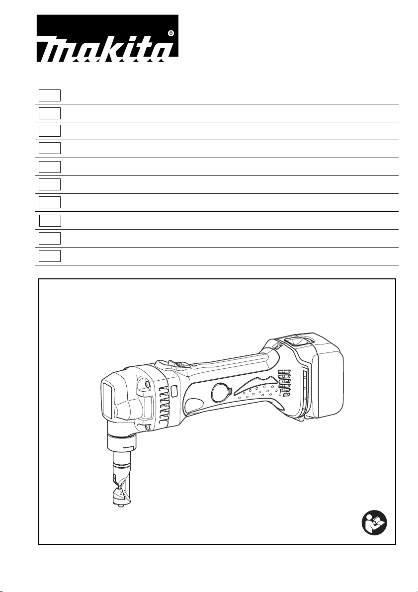
Intended use
The tool is intended for cutting sheet steel and stainless
sheet steel.
General Power Tool Safety Warnings
WARNING Read all safety warnings and all
instructions. Failure to follow the warnings and
instructions may result in electric shock, fire and/or
serious injury.
Save all warnings and instructions for future
reference.
11 No tch
12 Slide switch
13 Indicating lamp
14 Die
15 Bolts
16 Hex wrench
17 Punch
18 Punch holder
19 Screw
20 Tighten
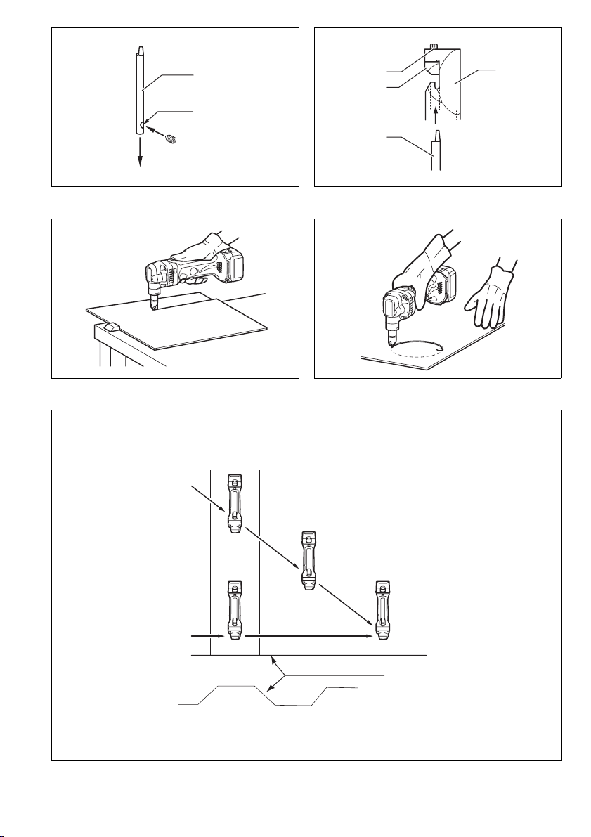
21 From the top view
22 Cutting at an angle to grooves
Steel up to 400 N/mm
Steel up to 600 N/mm
2
2
Outside edge 50 mm 50 mm
Inside edge 45 mm 45 mm
–1
) 1,900 1,900
ENE037-1
GEA010-1
23 Cutting perpendicular to
grooves
24 From the side view
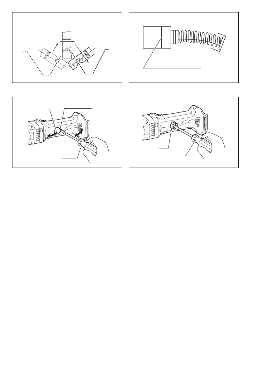
25 Corrugated or trapezoidal sheet
metal
26 Cutting head should be at a
right angle (90°) to cutting sur-
face.
27 Limit mark
28 Holder cap cover
29 Screwdriver
30 Brush holder cap
1.6 mm/16 ga 1.6 mm/16 ga
1.2 mm/18 ga 1.2 mm/18 ga
2
2.5 mm/12 ga 2.5 mm/12 ga
NIBBLER SAFETY WARNINGS
1. Hold the tool firmly.
2. Secure the workpiece firmly.
3. Keep hands away from moving parts.
4. Edges and chips of the workpiece are sharp.
Wear gloves. It is also recommended that you
put on thickly bottomed shoes to prevent injury.
5. Do not put the tool on the chips of the workpiece. Otherwise it can cause damage and trouble on the tool.
6. Do not leave the tool running. Operate the tool
only when hand-held.
7. Always be sure you have a firm footing.
Be sure no one is below when using the tool in
high locations.
8. Do not touch the punch, die or the workpiece
immediately after operation; they may be
extremely hot and could burn your skin.
9. Avoid cutting electrical wires. It can cause serious accident by electric shock.
SAVE THESE INSTRUCTIONS.
WARNI NG:
DO NOT let comfort or familiarity with product
(gained from repeated use) replace strict adherence
to safety rules for the subject product. MISUSE or
failure to follow the safety rules stated in this instruction manual may cause serious personal injury.
GEB028-2
5

ENC007-8
IMPORTANT SAFETY INSTRUCTIONS
FOR BATTERY CARTRIDGE
1. Before using battery cartridge, read all instructions and cautionary markings on (1) battery
charger, (2) battery, and (3) product using battery.
2. Do not disassemble battery cartridge.
3. If operating time has become excessively
shorter, stop operating immediately. It may
result in a risk of overheating, possible burns
and even an explosion.
4. If electrolyte gets into your eyes, rinse them out
with clear water and seek medical attention right
away. It may result in loss of your eyesight.
5. Do not short the battery cartridge:
(1) Do not touch the terminals with any conduc-
tive material.
(2) Avoid storing battery cartridge in a con-
tainer with other metal objects such as nails,
coins, etc.
(3) Do not expose battery cartridge to water or
rain.
A battery short can cause a large current flow,
overheating, possible burns and even a breakdown.
6. Do not store the tool and battery cartridge in
locations where the temperature may reach or
exceed 50°C (122°F).
7. Do not incinerate the battery cartridge even if it
is severely damaged or is completely worn out.
The battery cartridge can explode in a fire.
8. Be careful not to drop or strike battery.
9. Do not use a damaged battery.
10. Follow your local regulations relating to disposal
of battery.
SAVE THESE INSTRUCTIONS.
Tips for maintaining maximum battery life
1. Charge the battery cartridge before completely
discharged.
Always stop tool operation and charge the battery cartridge when you notice less tool power.
2. Never recharge a fully charged battery cartridge.
Overcharging shortens the battery service life.
3. Charge the battery cartridge with room temperature at 10°C – 40°C (50°F – 104°F). Let a hot battery cartridge cool down before charging it.
4. Charge the battery cartridge once in every six
months if you do not use it for a long period of
time.
FUNCTIONAL DESCRIPTION
CAUTION:
• Always be sure that the tool is switched off and the bat-
tery cartridge is removed before adjusting or checking
function on the tool.
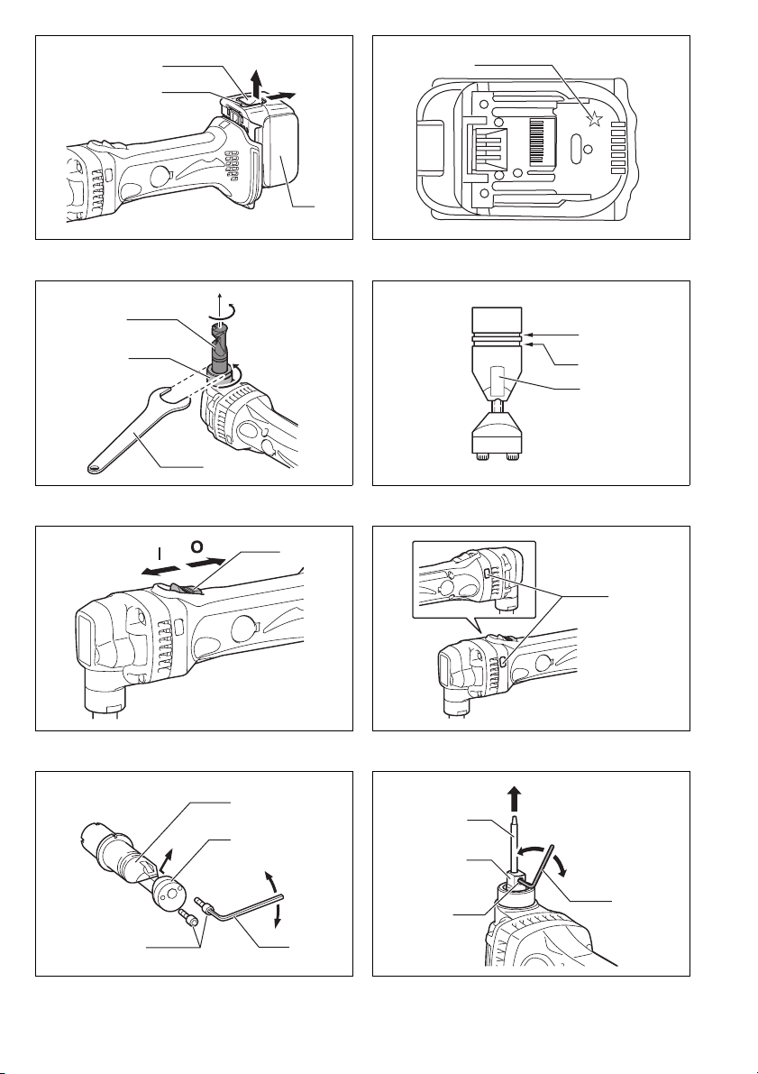
Installing or removing battery cartridge (Fig. 1)
CAUTION:
• Always switch off the tool before installing or removing
of the battery cartridge.
• Hold the tool and the battery cartridge firmly when
installing or removing battery cartridge. Failure to
hold the tool and the battery cartridge firmly may cause
them to slip off your hands and result in damage to the
tool and battery cartridge and a personal injury.
To remove the battery cartridge, slide it from the tool
while sliding the button on the front of the cartridge.
To install the battery cartridge, align the tongue on the
battery cartridge with the groove in the housing and slip it
into place. Insert it all the way until it locks in place with a
little click. If you can see the red indicator on the upper
side of the button, it is not locked completely.
CAUTION:
• Always install the battery cartridge fully until the red
indicator cannot be seen. If not, it may accidentally fall
out of the tool, causing injury to you or someone
around you.
• Do not install the battery cartridge forcibly. If the cartridge does not slide in easily, it is not being inserted
correctly.
Battery protection system (Fig. 2)
The tool is equipped with a battery protection system.
This system automatically cuts off power to the motor to
extend battery life.
The tool will automatically stop during operation if the
tool and/or battery are placed under one of the following
conditions:
• Overloaded:
The tool is operated in a manner that causes it to draw
an abnormally high current.
In this situation, turn the tool off and stop the application that caused the tool to become overloaded. Then
turn the tool on to restart.
If the tool does not start, the battery is overheated. In
this situation, let the battery cool before turning the tool
on again.
• Low battery voltage:
The remaining battery capacity is too low and the tool
will not operate. In this situation, remove and recharge
the battery.
NOTE:
• The overheat protection works only with a battery cartridge with a star mark.
Changing the die position (Fig. 3)
The die holder position can be changed 360°. To change
it, proceed as follows.
1. Loosen the lock nut with the wrench provided.
2. Pull the die holder slightly and turn it to the desired
position for operation.
3. Tighten the lock nut to secure the die holder in the
desired position.
There are four positive stops at 90° each: 0°, 90° left and
right and 180°. To position the die to any of these positive
stops:
4. Loosen the lock nut with the wrench provided.
5. Pull the die holder slightly and depress lightly while
turning it to the desired position. The die holder will
lock into one of the positive stop positions as desired.
6. Turn the die holder slightly to make sure that it is posi-
tively locked into position.
7. Tighten the lock nut to secure the die holder.
6
 Loading...