

Page 1
INSTRUCTION MANUAL
MANUEL D'INSTRUCTION
MANUAL DE INSTRUCCIONES
Cordless Angle Grinder
Meuleuse d’Angle sans Fil
Esmeriladora Angular Inalámbrica
DGA405
DGA455
DGA505
IMPORTANT: Read Before Using.
IMPORTANT: Lire avant usage.
IMPORTANTE: Leer antes de usar.
015305
1
Page 2

ENGLISH (Original instructions)
SPECIFICATIONS
Model DGA405 DGA455 DGA505
Wheel diameter 100 mm (4") 115 mm (4-1/2") 125 mm (5")
Max. wheel thickness 6 mm (1/4") 6 mm (1/4") 6 mm (1/4")
Spindle thread M10 X 1.25 5/8"
Rated speed (n) / No load speed (n0) 8,500 /min
Overall length
Net weight
• Due to our continuing program of research and development, the specifications herein are subject to change without notice.
• Specifications and battery cartridge may differ from country to country.
• Weight, with battery cartridge, according to EPTA-Procedure 01/2003
General Power Tool Safety Warnings
WARNING Read all safety warnings and all
instructions.
may result in electric shock, fire and/or serious injury.
Save all warnings and
instructions for future reference.
The term "power tool" in the warnings refers to your
mains-operated (corded) power tool or battery-operated
(cordless) power tool.
Work area safety
1. Keep work area clean and well lit. Cluttered or
dark areas invite accidents.
2. Do not operate power tools in explosive
atmospheres, such as in the presence of
flammable liquids, gases or dust. Power tools
create sparks which may ignite the dust or fumes.
3. Keep children and bystanders away while
operating a power tool. Distractions can cause
you to lose control.
Electrical safety
4. Power tool plugs must match the outlet. Never
modify the plug in any way. Do not use any
adapter plugs with earthed (grounded) power
tools. Unmodified plugs and matching outlets will
reduce risk of electric shock.
5. Avoid body contact with earthed or grounded
surfaces such as pipes, radiators, ranges and
refrigerators. There is an increased risk of
With battery cartridge BL1815N, BL1820, BL1820B
With battery cartridge BL1830, BL1830B,
BL1840, BL1840B, BL1850, BL1850B, BL1860B
With battery cartridge BL1815N, BL1820, BL1820B
With battery cartridge BL1830, BL1830B,
BL1840, BL1840B, BL1850, BL1850B, BL1860B
Rated voltage D.C. 18 V
Standard battery cartridge
GEA006-2
Failure to follow the warnings and instructions
2.2 kg (4.8 lbs) 2.3 kg (5.1 lbs) 2.3 kg (5.1 lbs)
2.4 kg (5.4 lbs) 2.5 kg (5.6 lbs) 2.6 kg (5.7 lbs)
BL1815N, BL1820, BL1820B, BL1830, BL1830B, BL1840,
electric shock if your body is earthed or grounded.
6. Do not expose power tools to rain or wet
conditions. Water entering a power tool will
increase the risk of electric shock.
7. Do not abuse the cord. Never use the cord for
carrying, pulling or unplugging the power tool.
Keep cord away from heat, oil, sharp edges or
moving parts. Damaged or entangled cords
increase the risk of electric shock.
8.
When operating a power tool outdoors, use an
extension cord suitable for outdoor use.
suitable for outdoor use reduces the risk of electric shock.
9. If operating a power tool in a damp location is
unavoidable, use a ground fault circuit
interrupter (GFCI) protected supply. Use of an
GFCI reduces the risk of electric shock.
Personal safety
10.
Stay alert, watch what you are doing and use
common sense when operating a power tool. Do
not use a power tool while you are tired or under
the influence of drugs, alcohol or medication.
moment of inattention while operating power tools
may result in serious personal injury.
11. Use personal protective equipment. Always
wear eye protection. Protective equipment such
as dust mask, non-skid safety shoes, hard hat, or
hearing protection used for appropriate conditions
will reduce personal injuries.
12. Prevent unintentional starting. Ensure the
switch is in the off-position before connecting
to power source and/or battery pack, picking
up or carrying the tool. Carrying power tools
2
348 mm (13-3/4")
362 mm (14-1/4")
BL1840B, BL1850, BL1850B, BL1860B
Use of a cord
A
Page 3

with your finger on the switch or energising power
tools that have the switch on invites accidents.
13. Remove any adjusting key or wrench before
turning the power tool on. A wrench or a key
left attached to a rotating part of the power tool
may result in personal injury.
14. Do not overreach. Keep proper footing and
balance at all times. This enables better control
of the power tool in unexpected situations.
15.
Dress properly. Do not wear loose clothing or
jewellery. Keep your hair, clothing, and gloves
away from moving parts.
or long hair can be caught in moving parts.
16.
If devices are provided for the connection of dust
extraction and collection facilities, ensure these
are connected and properly used.
collection can reduce dust-related hazards.
Power tool use and care
17. Do not force the power tool. Use the correct
power tool for your application. The correct
power tool will do the job better and safer at the
rate for which it was designed.
18. Do not use the power tool if the switch does
not turn it on and off. Any power tool that
cannot be controlled with the switch is dangerous
and must be repaired.
19.
Disconnect the plug from the power source and/or
the battery pack from the power tool before making
any adjustments, changing accessories, or storing
power tools.
the risk of starting the power tool accidentally.
20. Store idle power tools out of the reach of
children and do not allow persons unfamiliar
with the power tool or these instructions to
operate the power tool. Power tools are
dangerous in the hands of untrained users.
21.
Maintain power tools. Check for misalignment or
binding of moving parts, breakage of parts and
any other condition that may affect the power
tool’s operation. If damaged, have the power tool
repaired before use.
poorly maintained power tools.
22. Keep cutting tools sharp and clean. Properly
maintained cutting tools with sharp cutting edges
are less likely to bind and are easier to control.
23. Use the power tool, accessories and tool bits
etc. in accordance with these instructions,
taking into account the working conditions
and the work to be performed. Use of the
power tool for operations different from those
intended could result in a hazardous situation.
Battery tool use and care
24. Recharge only with the charger specified by
the manufacturer. A charger that is suitable for
one type of battery pack may create a risk of fire
Such preventive safety measures reduce
Loose clothes, jewellery
Use of dust
Many accidents are caused by
when used with another battery pack.
25. Use power tools only with specifically
designated battery packs. Use of any other
battery packs may create a risk of injury and fire.
26. When battery pack is not in use, keep it away
from other metal objects, like paper clips,
coins, keys, nails, screws or other small metal
objects, that can make a connection from one
terminal to another. Shorting the battery
terminals together may cause burns or a fire.
27. Under abusive conditions, liquid may be
ejected from the battery; avoid contact. If
contact accidentally occurs, flush with water.
If liquid contacts eyes, additionally seek
medical help. Liquid ejected from the battery
may cause irritation or burns.
Service
28. Have your power tool serviced by a qualified
repair person using only identical
replacement parts. This will ensure that the
safety of the power tool is maintained.
29. Follow instruction for lubricating and
changing accessories.
30. Keep handles dry, clean and free from oil and
grease.
GEB059-3
CORDLESS GRINDER SAFETY
WARNINGS
Safety Warnings Common for Grinding, Sanding,
Wire Brushing, or Abrasive Cutting-Off Operations:
1.
This power tool is intended to function as a grinder,
sander, wire brush or cut-off tool. Read all safety
warnings, instructions, illustrations and
specifications provided with this power tool.
to follow all instructions listed below may result in
electric shock, fire and/or serious injury.
2.
Operations such as polishing are not
recommended to be performed with this power tool.
Operations for which the power tool was not designed
may create a hazard and cause personal injury.
3. Do not use accessories which are not
specifically designed and recommended by
the tool manufacturer. Just because the
accessory can be attached to your power tool, it
does not assure safe operation.
4. The rated speed of the accessory must be at
least equal to the maximum speed marked on
the power tool. Accessories running faster than
their rated speed can break and fly apart.
5.
The outside diameter and the thickness of your
accessory must be within the capacity rating of
your power tool.
cannot be adequately guarded or controlled.
3
Incorrectly sized accessories
Failure
Page 4

6. Threaded mounting of accessories must
match the grinder spindle thread. For
accessories mounted by flanges, the arbour
hole of the accessory must fit the locating
diameter of the flange. Accessories that do not
match the mounting hardware of the power tool
will run out of balance, vibrate excessively and
may cause loss of control.
7.
Do not use a damaged accessory. Before each use
inspect the accessory such as abrasive wheels for
chips and cracks, backing pad for cracks, tear or
excess wear, wire brush for loose or cracked wires.
If power tool or accessory is dropped, inspect for
damage or install an undamaged accessory. After
inspecting and installing an accessory, position
yourself and bystanders away from the plane of the
rotating accessory and run the power tool at
maximum no-load speed for one minute.
Damaged
accessories will normally break apart during this test
time.
8.
Wear personal protective equipment. Depending on
application, use face shield, safety goggles or
safety glasses. As appropriate, wear dust mask,
hearing protectors, gloves and workshop apron
capable of stopping small abrasive or workpiece
fragments.
The eye protection must be capable of
stopping flying debris generated by various operations .
The dust mask or respirator must be capable of
filtrating particles generated by your operation.
Prolonged exposure to high intensity noise may cause
hearing loss.
9. Keep bystanders a safe distance away from
work area. Anyone entering the work area
must wear personal protective equipment.
Fragments of workpiece or of a broken accessory
may fly away and cause injury beyond immediate
area of operation.
10. Hold the power tool by insulated gripping
surfaces only, when performing an operation
where the cutting tool may contact hidden
wiring. Contact with a "live" wire will also make
exposed metal parts of the power tool "live" and
could give the operator an electric shock.
11. Never lay the power tool down until the
accessory has come to a complete stop. The
spinning accessory may grab the surface and pull
the power tool out of your control.
12. Do not run the power tool while carrying it at
your side. Accidental contact with the spinning
accessory could snag your clothing, pulling the
accessory into your body.
13. Regularly clean the power tool’s air vents. The
motor’s fan will draw the dust inside the housing
and excessive accumulation of powdered metal
may cause electrical hazards.
14. Do not operate the power tool near flammable
materials. Sparks could ignite these materials.
15. Do not use accessories that require liquid
coolants. Using water or other liquid coolants
may result in electrocution or shock.
Kickback and Related Warnings
Kickback is a sudden reaction to a pinched or snagged
rotating wheel, backing pad, brush or any other accessory.
Pinching or snagging causes rapid stalling of the rotating
accessory which in turn causes the uncontrolled power tool
to be forced in the direction opposite of the accessory’s
rotation at the point of the binding.
For example, if an abrasive wheel is snagged or pinched by
the workpiece, the edge of the wheel that is entering into the
pinch point can dig into the surface of the material causing
the wheel to climb out or kick out. The wheel may either jump
toward or away from the operator, depending on direction of
the wheel’s movement at the point of pinching. Abrasive
wheels may also break under these conditions.
Kickback is the result of power tool misuse and/or
incorrect operating procedures or conditions and can be
avoided by taking proper precautions as given below.
a) Maintain a firm grip on the power tool and
position your body and arm to allow you to
resist kickback forces. Always use auxiliary
handle, if provided, for maximum control over
kickback or torque reaction during start-up.
The operator can control torque reactions or
kickback forces, if proper precautions are taken.
b)
Never place your hand near the rotating
accessory.
Accessory may kickback over your hand.
c) Do not position your body in the area where
power tool will move if kickback occurs.
Kickback will propel the tool in direction opposite
to the wheel’s movement at the point of snagging.
d) Use special care when working corners,
sharp edges etc. Avoid bouncing and snagging
the accessory. Corners, sharp edges or bouncing
have a tendency to snag the rotating accessory
and cause loss of control or kickback.
e) Do not attach a saw chain woodcarving
blade or toothed saw blade. Such blades create
frequent kickback and loss of control.
Safety Warnings Specific for Grinding and Abrasive
Cutting-Off Operations:
a) Use only wheel types that are recommended
for your power tool and the specific guard
designed for the selected wheel. Wheels for
which the power tool was not designed cannot be
adequately guarded and are unsafe.
b) The grinding surface of centre depressed
wheels must be mounted below the plane of
the guard lip. An improperly mounted wheel that
projects through the plane of the guard lip cannot
be adequately protected.
4
Page 5

c)
The guard must be securely attached to the
power tool and positioned for maximum safety, so
the least amount of wheel is exposed towards the
operator.
The guard helps to protect the operator from
broken wheel fragments, accidental contact with wheel
and sparks that could ignite clothing.
d) Wheels must be used only for recommended
applications. For example: do not grind with
the side of cut-off wheel. Abrasive cut-off wheels
are intended for peripheral grinding, side forces
applied to these wheels may cause them to shatter.
e)
Always use undamaged wheel flanges that are of
correct size and shape for your selected wheel.
Proper wheel flanges support the wheel thus reducing
the possibility of wheel breakage. Flanges for cut-off
wheels may be different from grinding wheel flanges.
f) Do not use worn down wheels from larger
power tools. Wheel intended for larger power tool
is not suitable for the higher speed of a smaller
tool and may burst.
Additional Safety Warnings Specific for Abrasive
Cutting-Off Operations:
a) Do not “jam” the cut-off wheel or apply
excessive pressure. Do not attempt to make an
excessive depth of cut. Overstressing the wheel
increases the loading and susceptibility to twisting
or binding of the wheel in the cut and the
possibility of kickback or wheel breakage.
b) Do not position your body in line with and
behind the rotating wheel. When the wheel, at
the point of operation, is moving away from your
body, the possible kickback may propel the
spinning wheel and the power tool directly at you.
c)
When wheel is binding or when interrupting a
cut for any reason, switch off the power tool
and hold the power tool motionless until the
wheel comes to a complete stop. Never attempt
to remove the cut-off wheel from the cut while
the wheel is in motion otherwise kickback may
occur.
Investigate and take corrective action to
eliminate the cause of wheel binding.
d)
Do not restart the cutting operation in the
workpiece. Let the wheel reach full speed and
carefully re-enter the cut.
The wheel may bind, walk up
or kickback if the power tool is restarted in the workpiece.
e) Support panels or any oversized workpiece
to minimize the risk of wheel pinching and
kickback. Large workpieces tend to sag under
their own weight. Supports must be placed under
the workpiece near the line of cut and near the
edge of the workpiece on both sides of the wheel.
f) Use extra caution when making a “pocket
cut” into existing walls or other blind areas.
The protruding wheel may cut gas or water pipes,
electrical wiring or objects that can cause kickback.
Safety Warnings Specific for Sanding Operations:
a) Do not use excessively oversized sanding
disc paper. Follow manufacturers
recommendations, when selecting sanding
paper. Larger sanding paper extending beyond
the sanding pad presents a laceration hazard and
may cause snagging, tearing of the disc or
kickback.
Safety Warnings Specific for Wire Brushing
Operations:
a) Be aware that wire bristles are thrown by the
brush even during ordinary operation. Do not
overstress the wires by applying excessive
load to the brush. The wire bristles can easily
penetrate light clothing and/or skin.
b) If the use of a guard is recommended for
wire brushing, do not allow interference of the
wire wheel or brush with the guard. Wire wheel
or brush may expand in diameter due to work load
and centrifugal forces.
Additional safety warnings:
16. When using depressed centre grinding
wheels, be sure to use only fiberglassreinforced wheels.
17. NEVER USE Stone Cup type wheels with this
grinder. This grinder is not designed for these
types of wheels and the use of such a product
may result in serious personal injury.
18. Be careful not to damage the spindle, the
flange (especially the installing surface) or the
lock nut. Damage to these parts could result
in wheel breakage.
19. Make sure the wheel is not contacting the
workpiece before the switch is turned on.
20. Before using the tool on an actual workpiece,
let it run for a while. Watch for vibration or
wobbling that could indicate poor installation
or a poorly balanced wheel.
21. Use the specified surface of the wheel to
perform the grinding.
22. Do not leave the tool running. Operate the tool
only when hand-held.
23. Do not touch the workpiece immediately after
operation; it may be extremely hot and could
burn your skin.
24. Observe the instructions of the manufacturer
for correct mounting and use of wheels.
Handle and store wheels with care.
25. Do not use separate reducing bushings or
adaptors to adapt large hole abrasive wheels.
26. Use only flanges specified for this tool.
27. For tools intended to be fitted with threaded
hole wheel, ensure that the thread in the
wheel is long enough to accept the spindle
length.
5
Page 6

28. Check that the workpiece is properly
supported.
29. Pay attention that the wheel continues to
rotate after the tool is switched off.
30. If working place is extremely hot and humid,
or badly polluted by conductive dust, use a
short-circuit breaker (30 mA) to assure
operator safety.
31. Do not use the tool on any materials
containing asbestos.
32. When use cut-off wheel, always work with the
dust collecting wheel guard required by
domestic regulation.
33. Cutting discs must not be subjected to any
lateral pressure.
SAVE THESE INSTRUCTIONS.
WARNING:
DO NOT let comfort or familiarity with product
(gained from repeated use) replace strict adherence
to safety rules for the subject product. MISUSE or
failure to follow the safety rules stated in this
instruction manual may cause serious personal
injury.
USD311-1
Symbols
The followings show the symbols used for tool.
・ volts
・ direct current
・ rated speed
・ no load speed
・ revolutions or reciprocation per minute
ENC007-10
IMPORTANT SAFETY
INSTRUCTIONS
FOR BATTERY CARTRIDGE
1. Before using battery cartridge, read all
instructions and cautionary markings on (1)
battery charger, (2) battery, and (3) product
using battery.
2. Do not disassemble battery cartridge.
3. If operating time has become excessively
shorter, stop operating immediately. It may
result in a risk of overheating, possible burns
and even an explosion.
4. If electrolyte gets into your eyes, rinse them
out with clear water and seek medical
attention right away. It may result in loss of
your eyesight.
5. Do not short the battery cartridge:
(1) Do not touch the terminals with any
conductive material.
(2) Avoid storing battery cartridge in a
container with other metal objects such
as nails, coins, etc.
(3) Do not expose battery cartridge to water
or rain.
A battery short can cause a large current flow,
overheating, possible burns and even a
breakdown.
6. Do not store the tool and battery cartridge in
locations where the temperature may reach or
exceed 50 ゚ C (122 ゚ F).
7. Do not incinerate the battery cartridge even if
it is severely damaged or is completely worn
out. The battery cartridge can explode in a fire.
8. Be careful not to drop or strike battery.
9. Do not use a damaged battery.
10. Follow your local regulations relating to
disposal of battery.
SAVE THESE INSTRUCTIONS.
CAUTION: Only use genuine Makita batteries.
Use of non-genuine Makita batteries, or batteries that
have been altered, may result in the battery bursting
causing fires, personal injury and damage. It will also
void the Makita warranty for the Makita tool and charger.
Tips for maintaining maximum battery life
1. Charge the battery cartridge before
completely discharged.
Always stop tool operation and charge the
battery cartridge when you notice less tool
power.
2. Never recharge a fully charged battery
cartridge.
Overcharging shortens the battery service life.
3. Charge the battery cartridge with room
temperature at 10 ゚ C - 40 ゚ C (50 ゚ F - 104 ゚ F).
Let a hot battery cartridge cool down before
charging it.
4. Charge the battery cartridge if you do not use
it for a long period (more than six months).
6
Page 7
FUNCTIONAL DESCRIPTION
CAUTION:
• Always be sure that the tool is switched off and the
battery cartridge is removed before adjusting or
checking function on the tool.
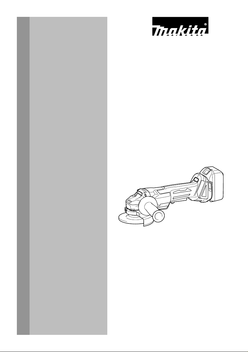
Installing or removing battery cartridge
1
2
015306
CAUTION:
• Always switch off the tool before installing or
removing of the battery cartridge.
•
Hold the tool and the battery cartridge firmly when
installing or removing battery cartridge.
hold the tool and the battery cartridge firmly may cause
them to slip off your hands and result in damage to the
tool and battery cartridge and a personal injury.
To remove the battery cartridge, slide it from the tool
while sliding the button on the front of the cartridge.
To install the battery cartridge, align the tongue on the
battery cartridge with the groove in the housing and slip
it into place. Insert it all the way until it locks in place
with a little click. If you can see the red indicator on the
upper side of the button, it is not locked completely.
CAUTION:
• Always install the battery cartridge fully until the
red indicator cannot be seen. If not, it may
accidentally fall out of the tool, causing injury to
you or someone around you.
•
Do not install the battery cartridge forcibly. If the cartridge
does not slide in easily, it is not being inserted correctly.
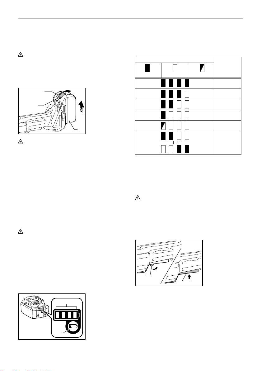
Indicating the remaining battery capacity
(Only for battery cartridges with "B" at the end of the
model number.)
1
2
015676
1. Button
2. Red indicator
3. Battery
cartridge
3
Failure to
1. Indicator lamps
2. CHECK button
Press the check button on the battery cartridge to
indicate the remaining battery capacity. The indicator
lamps light up for few seconds.
015658
Indicator lamps
Off
BlinkingLighted
Remaining
capacity
75% to 100%
50% to 75%
25% to 50%
0% to 25%
Charge the
battery.
The battery
may have
malfunctioned.
NOTE:
• Depending on the conditions of use and the
ambient temperature, the indication may differ
slightly from the actual capacity.
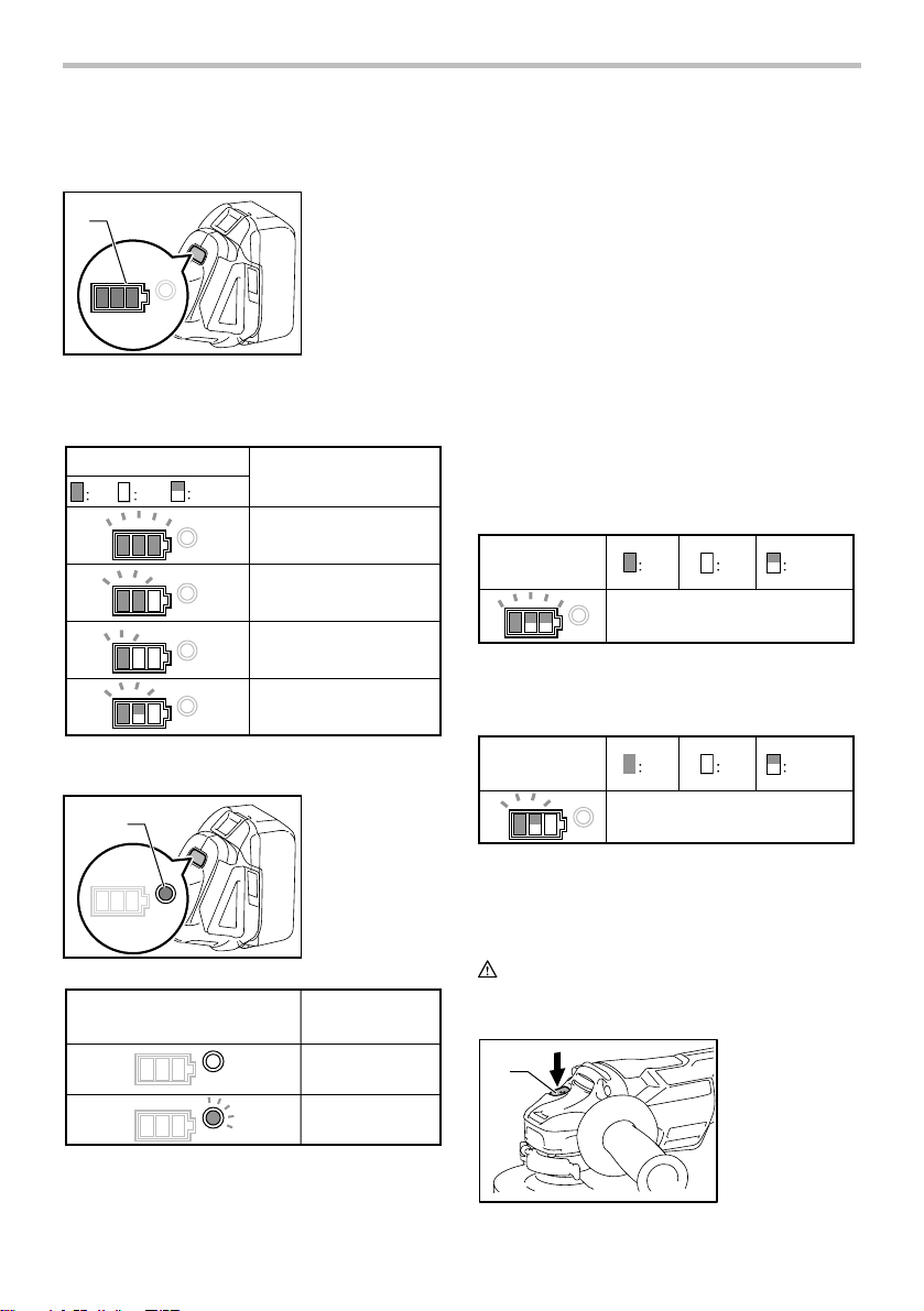
Switch action
CAUTION:
• Before installing the battery cartridge into the tool,
always check to see that the switch lever actuates
properly and returns to the "OFF" position when
released.
• Do not pull the switch lever hard without pulling
the lock-off lever. This can cause switch breakage.
1. Lock-off lever
2. Switch lever
1
015307
2
To prevent the switch lever from being accidentally
pulled, a lock-off lever is provided. To start the tool, pull
the lock-off lever toward the operator and then pull the
switch lever. Release the switch lever to stop.
Accidental re-start preventive function
Even if installing the battery cartridge while pulling the
switch lever, the tool does not start.
To start the tool, first release the switch lever. Then pull
the lock-off lever and then pull the switch lever.
7
Page 8
Indicating remaining battery capacity
(Country specific)
1
015141
When you turn the tool on, the battery indicator shows
the remaining battery capacity.
The remaining battery capacity is shown as the following table.
Battery indicator status
On Off
015096
Blinking
1. Battery indicator
Remaining battery capacity
50% - 100%
20% - 50%
0% - 20%
Charge the battery
Automatic speed change function
1
015142
Mode indicator status Operation mode
1. Mode indicator
High speed mode
depending on the work load. When mode indicator lights
up during operation, the tool is in high torque mode.
Tool / battery protection system
The tool is equipped with a tool/battery protection
system. This system automatically cuts off power to the
motor to extend tool and battery life.
The tool will automatically stop during operation if the
tool or battery is placed under one of the following
conditions. In some conditions, the indicator lights up.
Overload protection
When the tool is operated in a manner that causes it to
draw an abnormally high current, the tool automatically
stops without any indications. In this situation, turn the
tool off and stop the application that caused the tool to
become overloaded. Then turn the tool on to restart.
Overheat protection for tool
When the tool is overheated, the tool stops automatically and
the battery indicator shows following state. In this situation, let
the tool cool before turning the tool on again.
Battery indicator
015140
Releasing protection lock
When the protection system works repeatedly, the tool is
locked and the battery indicator shows the following state.
On Off Blinking
Tool is overheated
Battery indicator
015200
In this situation, the tool does not start even if turning the tool
off and on. To release the protection lock, remove the battery,
set it to the battery charger and wait until the charging finishes.
Shaft lock
CAUTION:
• Never actuate the shaft lock when the spindle is
moving. The tool may be damaged.
1
On Off Blinking
Protection lock works
1. Shaft lock
High torque mode
015098
This tool has "high speed mode" and "high torque
mode". It automatically changes operation mode
8
015308
Page 9
Press the shaft lock to prevent spindle rotation when
installing or removing accessories.
ASSEMBLY
CAUTION:
• Always be sure that the tool is switched off and the
battery cartridge is removed before carrying out
any work on the tool.
Installing side grip (handle)
CAUTION:
• Always be sure that the side grip is installed
securely before operation.
it can protect the operator according to work.
2
1
015085
1. Screw
2. Lever
3. Wheel guard
3
Tighten the lever to fasten the wheel guard. If the lever is too
tight or too loose to fasten the wheel guard, loosen or tighten
the screw to adjust the tightening of the wheel guard band.
To remove wheel guard, follow the installation
procedure in reverse.
For tool with locking screw type wheel guard
1. Wheel guard
2. Bearing box
3. Screw
015309
Screw the side grip securely on the position of the tool
as shown in the figure.
Installing or removing wheel guard
(For depressed center wheel, multi disc /
abrasive cut-off wheel, diamond wheel)
WARNING:
• When using a depressed center grinding
wheel/Multi-disc, flex wheel, wire wheel brush, cutoff wheel or diamond wheel, the wheel guard must
be fitted on the tool so that the closed side of the
guard always points toward the operator.
• When using an abrasive cut-off / diamond wheel,
be sure to use only the special wheel guard
designed for use with cut-off wheels.
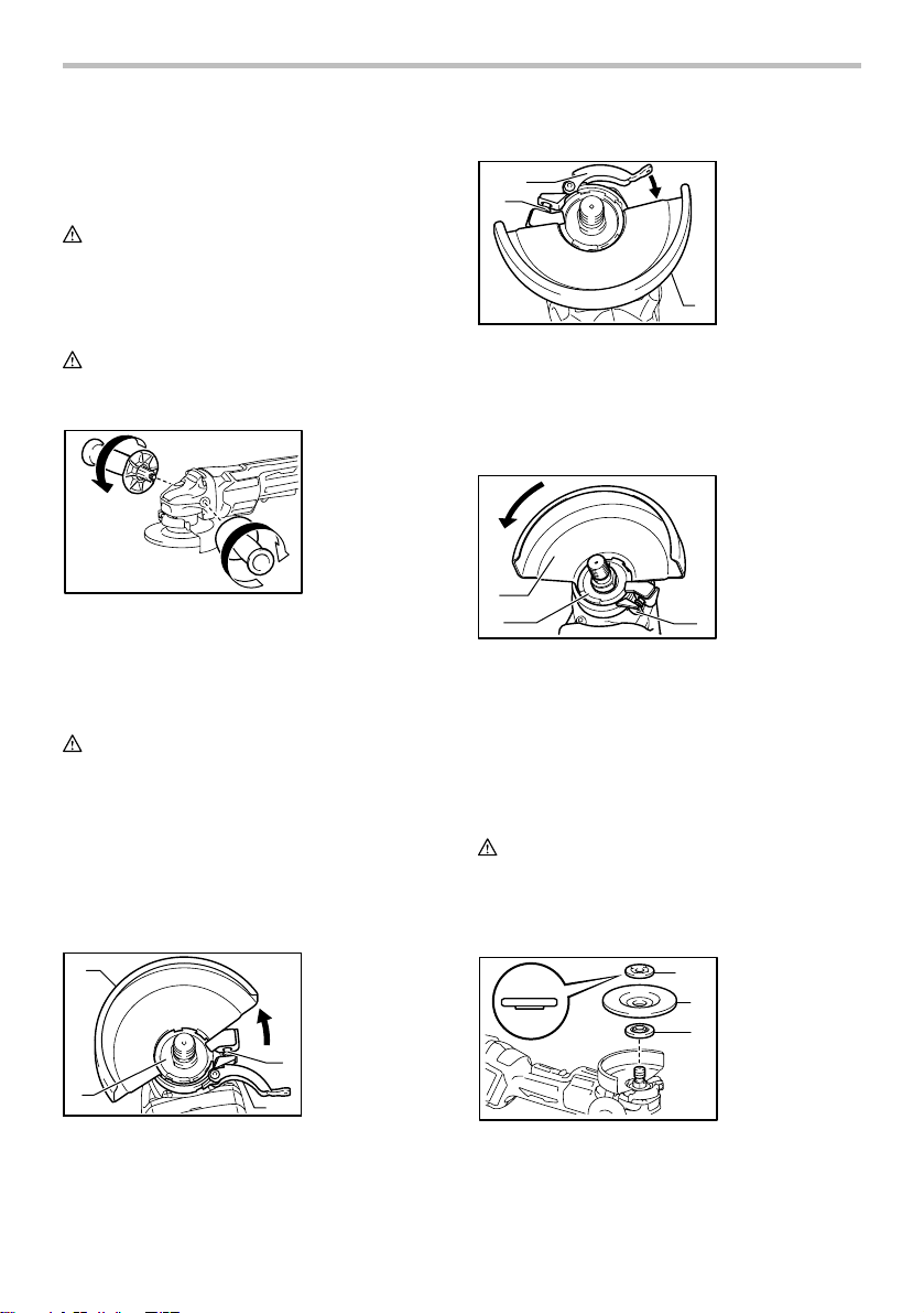
For tool with clamp lever type wheel guard
1
2
015084
Loosen the lever on the wheel guard after loosening the
screw. Mount the wheel guard with the protrusion on the
wheel guard band aligned with the notch on the bearing
box. Then rotate the wheel guard to such an angle that
1. Wheel guard
2. Bearing box
3. Screw
4. Lever
3
4
1
2
015303
3
Mount the wheel guard with the protrusion on the wheel guard
band aligned with the notch on the bearing box. Then rotate the
wheel guard to such an angle that it can protect the operator
according to work. Be sure to tighten the screw securely.
To remove wheel guard, follow the installation
procedure in reverse.
Installing or removing depressed center
wheel or multi disc (optional accessory)
WARNING:
•
When using a depressed center wheel or multi disc, the
wheel guard must be fitted on the tool so that the closed
side of the guard always points toward the operator.
•
Only actuate the shaft lock when the spindle is not moving.
1. Lock nut
1
2. Depressed
2
center wheel
3. Inner flange
3
015310
Mount the inner flange onto the spindle.
Make sure to fit the dented part of the inner flange onto
the straight part at the bottom of the spindle.
9
Page 10
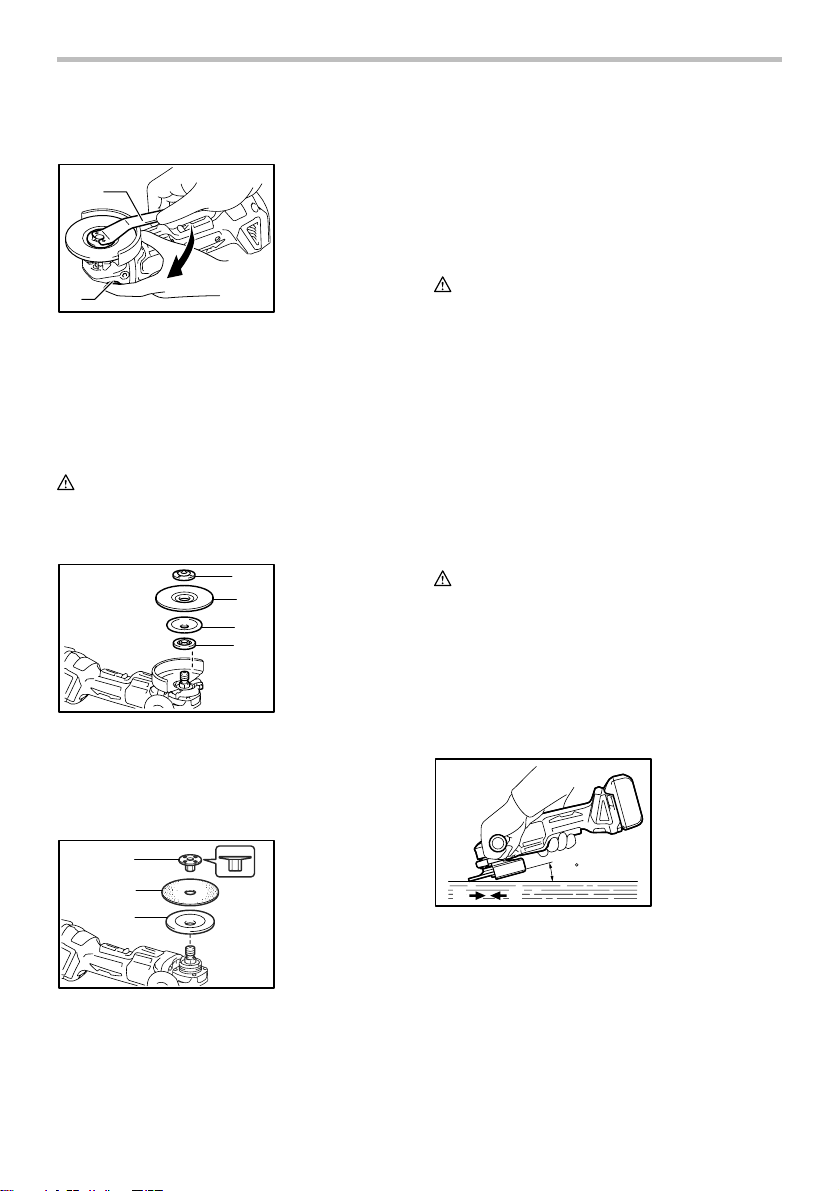
Fit the wheel/disc on the inner flange and screw the lock
nut onto the spindle.
1. Lock nut
1
2
015311
wrench
2. Shaft lock
To tighten the lock nut, press the shaft lock firmly so that
the spindle cannot revolve, then use the lock nut wrench
and securely tighten clockwise.
To remove the wheel, follow the installation procedure in
reverse.
Installing or removing flex wheel
(optional accessory)
WARNING:
• Always use supplied guard when flex wheel is on
tool. Wheel can shatter during use and guard
helps to reduce chances of personal injury.
1. Lock nut
1
2. Flex wheel
2
3. Plastic pad
4. Inner flange
3
4
015312
Follow instructions for depressed center grinding wheel/Multidisc but also use plastic pad over wheel. See order of
assembly on accessories page in this manual.
Installing or removing abrasive disc
(optional accessory)
1
2
3
015313
Mount the rubber pad onto the spindle. Fit the disc on the rubber
pad and screw the lock nut onto the spindle. To tighten the lock
nut, press the shaft lock firmly so that the spindle cannot revolve,
then use the lock nut wrench and securely tighten clockwise.
1. Sanding lock
nut
2. Abrasive disc
3. Rubber pad
To remove the disc, follow the installation procedure in
reverse.
NOTE:
• Use sander accessories specified in this manual.
These must be purchased separately.
OPERATION
WARNING:
• It should never be necessary to force the tool. The
weight of the tool applies adequate pressure.
Forcing and excessive pressure could cause
dangerous wheel breakage.
• ALWAYS replace wheel if tool is dropped while
grinding.
• NEVER bang or hit grinding disc or wheel onto
work.
• Avoid bouncing and snagging the wheel,
especially when working corners, sharp edges etc.
This can cause loss of control and kickback.
• NEVER use tool with wood cutting blades and
other sawblades. Such blades when used on a
grinder frequently kick and cause loss of control
leading to personal injury.
CAUTION:
• Never switch on the tool when it is in contact with
the workpiece, it may cause an injury to operator.
• Always wear safety goggles or a face shield during
operation.
• After operation, always switch off the tool and wait
until the wheel has come to a complete stop
before putting the tool down.
Grinding and sanding operation
15
B
A
015661
ALWAYS hold the tool firmly with one hand on housing
and the other on the side handle. Turn the tool on and
then apply the wheel or disc to the workpiece.
In general, keep the edge of the wheel or disc at an
angle of about 15 degrees to the workpiece surface.
During the break-in period with a new wheel, do not
work the grinder in the B direction or it will cut into the
workpiece. Once the edge of the wheel has been
rounded off by use, the wheel may be worked in both A
and B direction.
10
Page 11
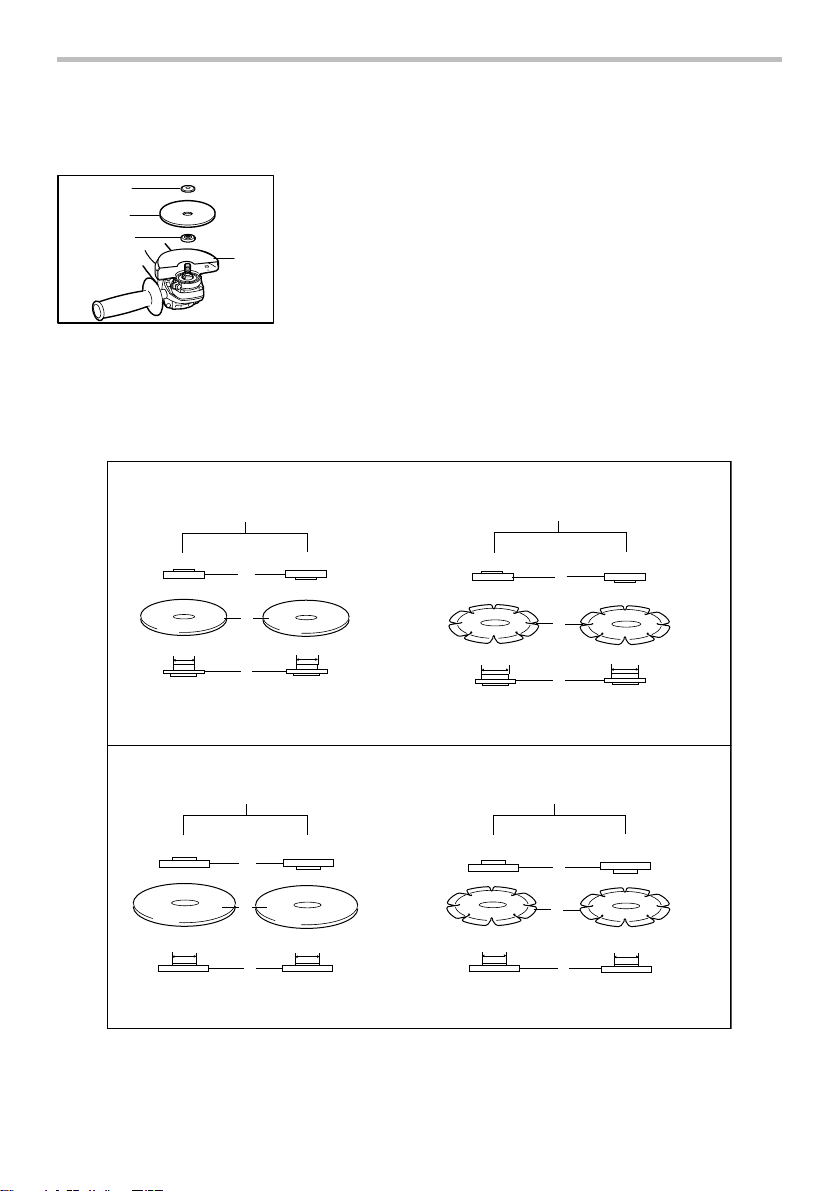
Operation with abrasive cut-off /
diamond wheel (optional accessory)
1
2
3
010855
Remove the battery cartridge from the tool and place it upside
down allowing easy access to spindle. Mount the inner flange
and abrasive cut-off / diamond wheel onto the spindle. Tighten
the lock nut securely with supplied wrench. The direction for
mounting the lock nut and the inner flange varies by wheel
thickness. Refer to the table below.
1. Lock nut
2. Abrasive cut-off
wheel/diamond
wheel
3. Inner flange
4
4. Wheel guard for
abrasive cut-off
wheel/diamond
wheel
100 mm (4")
Abrasive cut-off wheel
Diamond wheel
010848
Thickness: Less than 4 mm (5/32") Thickness: 4 mm (5/32") or more
1
2
16 mm (5/8")
16 mm (5/8")
3
Lock nut Abrasive cut-off wheelInner flange Diamond wheel
Thickness: Less than 4 mm (5/32") Thickness: 4 mm (5/32") or more
1
4
20 mm (13/16")
3
4.3.2.1.
115 mm (4 - 1/2") / 125 mm (5")
Abrasive cut-off wheel
Thickness: Less than 4 mm (5/32") Thickness: 4 mm (5/32") or more
1
2
22.23 mm (7/8")
22.23 mm (7/8")
3
Thickness: Less than 4 mm (5/32") Thickness: 4 mm (5/32") or more
11
Diamond wheel
1
4
22.23 mm (7/8") 22.23 mm (7/8")
3
4.3.2.1.Lock nut Abrasive cut-off wheelInner flange Diamond wheel
20 mm (13/16")
Page 12
WARNING:
• When using an abrasive cut-off / diamond wheel,
be sure to use only the special wheel guard
designed for use with cut-off wheels.
• NEVER use cut-off wheel for side grinding.
• Do not "jam" the wheel or apply excessive
pressure. Do not attempt to make an excessive
depth of cut. Overstressing the wheel increases
the loading and susceptibility to twisting or binding
of the wheel in the cut and the possibility of
kickback, wheel breakage and overheating of the
motor may occur.
• Do not start the cutting operation in the workpiece.
Let the wheel reach full speed and carefully enter
into the cut moving the tool forward over the
workpiece surface. The wheel may bind, walk up
or kickback if the power tool is started in the
workpiece.
• During cutting operations, never change the angle
of the wheel. Placing side pressure on the cut-off
wheel (as in grinding) will cause the wheel to crack
and break, causing serious personal injury.
• A diamond wheel shall be operated perpendicular
to the material being cut.
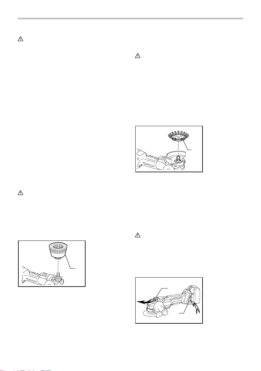
Operation with wire cup brush
(optional accessory)
CAUTION:
• Check operation of brush by running tool with no
load, insuring that no one is in front of or in line
with brush.
• Do not use brush that is damaged, or which is out
of balance. Use of damaged brush could increase
potential for injury from contact with broken brush
wires.
1. Wire cup brush
1
015315
Remove the battery cartridge from the tool and place it
upside down allowing easy access to spindle. Remove
any accessories on spindle. Thread wire cup brush onto
spindle and tighten with supplied wrench. When using
brush, avoid applying too much pressure which causes
over bending of wires, leading to premature breakage.
Operation with wire wheel brush
(optional accessory)
CAUTION:
• Check operation of wire wheel brush by running
tool with no load, insuring that no one is in front of
or in line with the wire wheel brush.
• Do not use wire wheel brush that is damaged, or
which is out of balance. Use of damaged wire
wheel brush could increase potential for injury
from contact with broken wires.
• ALWAYS use guard with wire wheel brushes,
assuring diameter of wheel fits inside guard.
Wheel can shatter during use and guard helps to
reduce chances of personal injury.
1. Wire wheel
brush
1
015316
Remove the battery cartridge from the tool and place it
upside down allowing easy access to spindle. Remove
any accessories on spindle. Thread wire wheel brush
onto spindle and tighten with the wrenches.
When using wire wheel brush, avoid applying too much
pressure which causes over bending of wires, leading to
premature breakage.
MAINTENANCE
CAUTION:
• Always be sure that the tool is switched off and the
battery cartridge is removed before attempting to
perform inspection or maintenance.
• Never use gasoline, benzine, thinner, alcohol or
the like. Discoloration, deformation or cracks may
result.
1. Exhaust vent
1
2
015317
The tool and its air vents have to be kept clean.
Regularly clean the tool's air vents or whenever the
vents start to become obstructed.
12
2. Inhalation vent
Page 13
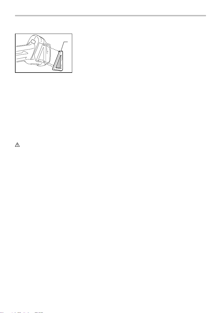
1. Dust cover
1
015087
Remove the dust cover from inhalation vent and clean it
for smooth air circulation.
NOTE:
• Clean out the dust cover when it is clogged with
dust or foreign matters. Continuing operation with
a clogged dust cover may damage the tool.
To maintain product SAFETY and RELIABILITY, repairs,
any other maintenance or adjustment should be
performed by Makita Authorized or Factory Service
Centers, always using Makita replacement parts.
OPTIONAL ACCESSORIES
CAUTION:
• These accessories or attachments are
recommended for use with your Makita tool
specified in this manual. The use of any other
accessories or attachments might present a risk of
injury to persons. Only use accessory or
attachment for its stated purpose.
• Your tool is supplied with a guard for use with a
depressed center grinding wheel, multi-disc, flex
wheel and wire wheel brush. A diamond wheel and
cut-off wheel are also available and should only be
used with the appropriate optional guard for cutoff
wheels. If you decide to use your Makita grinder
with approved accessories which you purchase
from your Makita distributor or factory service
center, be sure to obtain and use all necessary
fasteners and guards as recommended in this
manual. Your failure to do so could result in
personal injury to you and others.
If you need any assistance for more details regarding
these accessories, ask your local Makita Service Center.
• Makita genuine battery and charger
13
Page 14
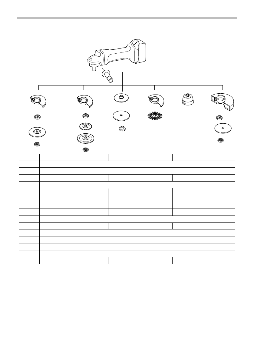
1
2
3
22
3
6
8
9
10
4
7
5
5
100 mm (4") model 115 mm (4-1/2") model 125 mm (5") model
1
2
3
Inner flange 35 Inner flange 45 Inner flange 45
4
5
6
7
8
Lock nut 10-35 Lock nut 5/8-45 Lock nut 5/8-45
Plastic pad
Flex wheel
Rubber pad 76
Wheel Guard (for grinding wheel)
Depressed center wheel/Multi-disc
9
10
Sanding lock nut 10-30
Sanding lock nut 5/8-48 Sanding lock nut 5/8-48
11
12
Wheel Guard
Abrasive cut-off wheel/Diamond wheel
015171
13
14
-
Lock nut wrench 20
NOTE:
• Some items in the list may be included in the tool
package as standard accessories. They may differ
from country to country.
12
11
13
3
14
5
Grip 36
-
-
-
-
Rubber pad 100 Rubber pad 115
Abrasive disc
Wire wheel brush
Wire cup brush
(for cut-off wheel)
Lock nut wrench 28 Lock nut wrench 28
14
Page 15

MAKITA LIMITED ONE YEAR WARRANTY
Warranty Policy
Every Makita tool is thoroughly inspected and tested
before leaving the factory. It is warranted to be free of
defects from workmanship and materials for the period
of ONE YEAR from the date of original purchase.
Should any trouble develop during this one year period,
return the COMPLETE tool, freight prepaid, to one of
Makita’s Factory or Authorized Service Centers. If
inspection shows the trouble is caused by defective
workmanship or material, Makita will repair (or at our
option, replace) without charge.
This Warranty does not apply where:
repairs have been made or attempted by others:
repairs are required because of normal wear and
tear:
the tool has been abused, misused or improperly
maintained:
alterations have been made to the tool.
IN NO EVENT SHALL MAKITA BE LIABLE FOR ANY
INDIRECT, INCIDENTAL OR CONSEQUENTIAL
DAMAGES FROM THE SALE OR USE OF THE
PRODUCT. THIS DISCLAIMER APPLIES BOTH
DURING AND AFTER THE TERM OF THIS
WARRANTY.
MAKITA DISCLAIMS LIABILITY FOR ANY IMPLIED
WARRANTIES, INCLUDING IMPLIED WARRANTIES
OF "MERCHANTABILITY" AND "FITNESS FOR A
SPECIFIC PURPOSE," AFTER THE ONE YEAR TERM
OF THIS WARRANTY.
This Warranty gives you specific legal rights, and you
may also have other rights which vary from state to
state. Some states do not allow the exclusion or
limitation of incidental or consequential damages, so
the above limitation or exclusion may not apply to you.
Some states do not allow limitation on how long an
implied warranty lasts, so the above limitation may not
apply to you.
EN0006-1
15
Page 16

FRANÇAIS (Mode d’emploi original)
SPÉCIFICATIONS
Modèle DGA405 DGA455 DGA505
Diamètre de la meule 100 mm (4") 115 mm (4-1/2") 125 mm (5")
Épaisseur max. meule 6 mm (1/4") 6 mm (1/4") 6 mm (1/4")
Vitesse nominale (n) / Vitesse à vide (n0) 8 500 /min
Longueur totale
Poids net
• Étant donné l'évolution constante de notre programme de recherche et de développement, les spécifications contenues dans ce
manuel sont sujettes à modification sans préavis.
• Les caractéristiques techniques et la batterie peuvent varier suivant les pays.
• Poids, batterie comprise, conforme à la procédure EPTA de 01/2003
Consignes de sécurité générales
pour outils électriques
MISE EN GARDE Veuillez lire toutes les mises
en garde de sécurité et toutes les instructions.
L'ignorance des mises en garde et des instructions
comporte un risque de choc électrique, d'incendie et/ou
de blessure grave.
Conservez toutes les mises en
garde et instructions pour
référence future.
Le terme ≪ outil électrique ≫ qui figure dans les
avertissements fait référence à un outil électrique
branché sur une prise de courant (par un cordon
d'alimentation) ou alimenté par batterie (sans fil).
Sécurité de la zone de travail
1. Maintenez la zone de travail propre et bien
éclairée. Les zones de travail encombrées ou
sombres ouvrent grande la porte aux accidents.
2. N'utilisez pas les outils électriques dans les
atmosphères explosives, par exemple en
présence de liquides, gaz ou poussières
inflammables. Les outils électriques produisent
des étincelles au contact desquelles la poussière
ou les vapeurs peuvent s'enflammer.
3. Assurez-vous qu'aucun enfant ou curieux ne
s'approche pendant que vous utilisez un outil
Filetage de l'arbre M10 x 1,25 5/8"
Avec la batterie BL1815N, BL1820, BL1820B
Avec la batterie BL1830, BL1830B, BL1840,
BL1840B, BL1850, BL1850B, BL1860B
Avec la batterie BL1815N, BL1820, BL1820B
Avec la batterie BL1830, BL1830B, BL1840,
BL1840B, BL1850, BL1850B, BL1860B
Tension nominale C.C. 18 V
Batterie standard
GEA006-2
2,2 kg (4,8 lbs) 2,3 kg (5,1 lbs) 2,3 kg (5,1 lbs)
2,4 kg (5,4 lbs) 2,5 kg (5,6 lbs) 2,6 kg (5,7 lbs)
BL1815N, BL1820, BL1820B, BL1830, BL1830B, BL1840,
électrique. Vous risquez de perdre la maîtrise de
348 mm (13-3/4")
362 mm (14-1/4")
BL1840B, BL1850, BL1850B, BL1860B
l'outil si votre attention est détournée.
Sécurité en matière d'électricité
4.
Les fiches d'outil électrique sont conçues pour
s'adapter parfaitement aux prises de courant. Ne
modifiez jamais la fiche de quelque façon que ce
soit. N'utilisez aucun adaptateur de fiche sur les
outils électriques avec mise à la terre.
modifiant pas les fiches et en les insérant dans des
prises de courant pour lesquelles elles ont été conçues
vous réduirez les risques de choc électrique.
5. Évitez tout contact corporel avec les surfaces
mises à la terre, telles que les tuyaux,
radiateurs, cuisinières et réfrigérateurs. Le
risque de choc électrique est plus élevé si votre
corps se trouve mis à la terre.
6. N'exposez pas les outils électriques à la pluie
ou à l'eau. La présence d'eau dans un outil
électrique augmente le risque de choc électrique.
7. Ne maltraitez pas le cordon. N'utilisez jamais
le cordon pour transporter, tirer ou
débrancher l'outil électrique. Maintenez le
cordon à l'écart des sources de chaleur, de
l'huile, des objets à bords tranchants et des
pièces en mouvement. Le risque de choc
électrique est plus élevé lorsque les cordons sont
endommagés ou enchevêtrés.
8.
Lorsque vous utilisez un outil électrique à
l'extérieur, utilisez un cordon prolongateur prévu à
cette fin.
Les risques de choc électrique sont moindres
lorsqu'un cordon conçu pour l'extérieur est utilisé.
16
En ne
Page 17

9. Si vous devez utiliser un outil électrique dans
un endroit humide, utilisez une source
d'alimentation protégée par un disjoncteur de
fuite à la terre. L'utilisation d'un disjoncteur de
fuite à la terre réduit le risque de choc électrique.
Sécurité personnelle
10.
Restez alerte, attentif à vos mouvements et
faites preuve de bon sens lorsque vous utilisez
un outil électrique. Évitez d'utiliser un outil
électrique si vous êtes fatigué ou si vous avez
pris une drogue, de l'alcool ou un médicament.
Un moment d'inattention pendant l'utilisation d'un
outil électrique peut entraîner une grave blessure.
11.
Portez des dispositifs de protection personnelle.
Portez toujours un protecteur pour la vue.
Les
risques de blessure seront moins élevés si vous utilisez
des dispositifs de protection tels qu'un masque
antipoussières, des chaussures à semelle antidérapante,
une coiffure résistante ou une protection d'oreilles.
12.
Évitez les démarrages accidentels. Assurez-vous
que l’interrupteur soit en position d'arrêt avant de
brancher l'outil à la prise électrique et/ou au blocpiles, avant de prendre ou de transporter l’outil.
Vous ouvrez la porte aux accidents si vous
transportez les outils électriques avec le doigt sur
l’interrupteur ou si vous les branchez alors que
l’interrupteur est en position de marche.
13. Retirez toute clé de réglage ou de serrage
avant de mettre l'outil sous tension. Toute c l é
laissée en place sur une pièce rotative de l'outil
électrique peut entraîner une blessure.
14. Maintenez une bonne position. Assurez-vous
d'une bonne prise au sol et d'une bonne
position d'équilibre en tout temps. Cela vous
permettra d'avoir une meilleure maîtrise de l'outil
dans les situations imprévues.
15. Portez des vêtements adéquats. Ne portez ni
vêtements amples ni bijoux. Vous devez
maintenir cheveux, vêtements et gants à
l'écart des pièces en mouvement. Les pièces
en mouvement peuvent happer les vêtements
amples, les bijoux et les cheveux longs.
16.
Si des accessoires sont fournis pour raccorder un
appareil d'aspiration et de collecte de la poussière,
assurez-vous qu'ils sont correctement raccordés et
qu'ils sont utilisés de manière adéquate.
L'utilisation
d'un appareil d'aspiration permet de réduire les risques
liés à la présence de poussière dans l'air.
Utilisation et entretien des outils électriques
17.
Ne forcez pas l'outil électrique. Utilisez l'outil
électrique adéquat suivant le type de travail à
effectuer.
Si vous utilisez l'outil électrique adéquat
et respectez le régime pour lequel il a été conçu, il
effectuera un travail de meilleure qualité et de façon
plus sécuritaire.
18.
N'utilisez pas l'outil électrique s'il n'est pas possible
de mettre sa gâchette en position de marche et
d'arrêt.
Un outil électrique dont l'interrupteur est
défectueux représente un danger et doit être réparé.
19.
Débranchez la fiche de la source d'alimentation
et/ou retirez le bloc-piles de l'outil électrique
avant d'effectuer tout réglage, de changer un
accessoire ou de ranger l'outil électrique.
telles mesures préventives réduisent les risques de
démarrage accidentel de l'outil électrique.
20.
Après l'utilisation d'un outil électrique, rangez-le
hors de portée des enfants et ne laissez aucune
personne l'utiliser si elle n'est pas familiarisée
avec l'outil électrique ou les présentes
instructions d'utilisation.
Les outils électriques
représentent un danger entre les mains de personnes
qui n'en connaissent pas le mode d'utilisation.
21. Veillez à l’entretien des outils électriques.
Assurez-vous que les pièces mobiles ne sont
pas désalignées ou coincées, qu’aucune
pièce n’est cassée et que l’outil électrique n’a
subi aucun dommage affectant son bon
fonctionnement. Le cas échéant, faites
réparer l'outil électrique avant de l'utiliser. De
nombreux accidents sont causés par des outils
électriques mal entretenus.
22. Maintenez les outils tranchants bien aiguisés
et propres. Un outil tranchant dont l'entretien est
effectué correctement et dont les bords sont bien
aiguisés risquera moins de se coincer et sera
plus facile à maîtriser.
23. Utilisez l'outil électrique, ses accessoires, ses
embouts, etc., en respectant les présentes
instructions, en tenant compte des conditions
de travail et du type de travail à effectuer.
L'utilisation d'un outil électrique à des fins autres
que celles prévues peut entraîner une situation
dangereuse.
Utilisation et entretien des outils alimentés par batterie
24. Pour recharger, utilisez uniquement le
chargeur spécifié par le fabricant. L'utilisation
d'un chargeur conçu pour un type donné de blocpiles comporte un risque d'incendie lorsqu'il est
utilisé avec un autre type de bloc-piles.
25. N'utilisez un outil électrique qu'avec le bloc-
piles conçu spécifiquement pour cet outil. Il y
a risque de blessure ou d'incendie si un autre
bloc-piles est utilisé.
26. Lorsque vous n'utilisez pas le bloc-piles,
rangez-le à l'écart des objets métalliques tels
que trombones, pièces de monnaie, clés,
clous, vis ou autres petits objets métalliques
qui risquent d'établir une connexion entre les
bornes. La mise en court-circuit des bornes de
batterie peut causer des brûlures ou un incendie.
17
De
Page 18

27. Dans des conditions d'utilisation inadéquates
de la batterie, il peut y avoir fuite d'électrolyte;
évitez tout contact avec ce liquide. En cas de
contact accidentel, rincez avec beaucoup
d’eau. Si le liquide pénètre dans vos yeux, il
faut aussi consulter un médecin. L'électrolyte
qui s'échappe de la batterie peut causer des
irritations ou des brûlures.
Réparation
28. Faites réparer votre outil électrique par un
réparateur qualifié qui utilise des pièces de
rechange identiques aux pièces d'origine. Le
maintien de la sûreté de l'outil électrique sera
ainsi assuré.
29. Suivez les instructions de lubrification et de
changement des accessoires.
30. Maintenez les poignées de l'outil sèches,
propres et exemptes d'huile ou de graisse.
GEB059-3
CONSIGNES DE SÉCURITÉ
POUR LA MEULEUSE SANS FIL
Mises en garde communes pour le meulage, le
ponçage, le brossage métallique ou le découpage
par meule abrasive :
1.
Cet outil électrique est conçu pour fonctionner
comme une meuleuse, une ponceuse, une
brosse métallique ou un outil de découpe.
Veuillez lire l'ensemble des mises en garde de
sécurité, instructions, illustrations et
spécifications fournies pour cet outil.
un risque de décharge électrique, d'incendie et/ou
de blessure grave si toutes les instructions
énumérées ci-dessous ne sont pas respectées.
2. Il n'est pas recommandé d'utiliser cet outil
électrique pour des opérations comme le
polissage. Les opérations pour lesquelles l'outil
n'a pas été conçu peuvent générer une situation
dangereuse et provoquer des blessures.
3. N'utilisez pas d'accessoire n'étant pas conçu
et recommandé spécifiquement par le
fabricant de l'outil. Même si vous pouvez fixer
l'accessoire à l'outil, cela ne garantit pas pour
autant un fonctionnement sécuritaire.
4.
La vitesse nominale de l'accessoire doit être au
moins égale à la vitesse maximale marquée sur
l'outil.
Les accessoires fonctionnant à une vitesse
supérieure à leur vitesse nominale peuvent se briser
et voler en morceau.
5. Le diamètre extérieur et l'épaisseur de votre
accessoire doivent respecter la capacité
nominale de votre outil. Il est impossible de
protéger ou de contrôler adéquatement les
accessoires d'une dimension inappropriée.
Il existe
6.
Le montage fileté d’accessoires doit être adapté au
filet de l'arbre de la meuleuse. Pour les accessoires
montés avec des flasques, l’alésage central de
l’accessoire doit s’adapter correctement au
diamètre de l’orifice de positionnement du flasque.
Les accessoires qui ne correspondent pas aux
éléments de montage de l’outil électrique seront en
déséquilibre, vibreront de manière excessive et
risqueront de provoquer une perte de contrôle.
7.
N'utilisez pas un accessoire s'il est endommagé.
Avant chaque utilisation, examinez les
accessoires : présence de copeaux et fissures sur
les meules abrasives, de fissures, déchirures ou
d'usure excessive sur la plaque de presse et de fils
desserrés ou fissurés sur la brosse métallique. Si
un outil électrique ou un accessoire subit une
chute, vérifiez s'il n'a pas été endommagé ou
installez un nouvel accessoire. Après avoir
inspecté et installé un accessoire, faites en sorte
que tout le monde (vous-même, les curieux) se
trouve hors de portée de l'accessoire rotatif.
Ensuite, faites fonctionner l'outil à sa vitesse à vide
maximale durant une minute.
accessoire est endommagé il se brisera durant ce test.
8. Portez un équipement de protection
individuelle. Selon l'application, utilisez un
écran facial ou des lunettes de sécurité.
Lorsque la situation le nécessite, portez un
masque anti-poussière, un appareil antibruit,
des gants et un tablier capable d'arrêter les
petits fragments abrasifs ou ceux de l'ouvrage.
L'appareil de protection des yeux doit être en
mesure d'arrêter les débris projetés par toutes les
opérations. Le masque anti-poussière ou le
respirateur doit être capable de filtrer les
particules générées par l'opération que vous
effectuez. Une exposition prolongée à un bruit de
forte intensité peut provoquer une perte de l'ouïe.
9. Maintenez les curieux à une distance
sécuritaire de la zone de travail. Toute
personne entrant dans la zone de travail doit
porter un équipement de protection
individuelle. Il est possible que des fragments de
l'ouvrage ou d'un accessoire brisé soient
propulsés et provoquent des blessures hors de la
zone immédiate de fonctionnement.
10. Tenez uniquement l'outil électrique par ses
surfaces de prise isolées pendant toute
opération où l'outil de coupe pourrait venir en
contact avec un câblage dissimulé. En cas de
contact avec un conducteur sous tension, les
pièces métalliques à découvert de l'outil
deviendraient également sous tension et
risqueraient de transmettre une décharge à
l'utilisateur.
18
Généralement, si un
Page 19

11. Ne reposez jamais l'outil tant que l'accessoire
n'est pas complètement arrêté. L'accessoire
rotatif pourrait s'agripper à la surface et rendre
l'outil incontrôlable.
12. Ne faites pas fonctionner l'outil lorsque vous
le transportez. Un contact accidentel avec
l'accessoire rotatif pourrait accrocher vos
vêtements et entraîner l'accessoire vers votre
corps.
13. Nettoyez régulièrement les fentes d’aération.
Le ventilateur du moteur attirera la poussière à
l’intérieur du boîtier et une accumulation
excessive de métal fritté pourrait provoquer des
dangers électriques.
14. N'utilisez pas l'outil électrique près de
matériaux inflammables. Les étincelles qui
jaillissent de l'outil risqueraient de faire prendre
en feu ces matériaux.
15. N'utilisez pas d'accessoires nécessitant de
réfrigérants fluides. L'utilisation d'eau ou d'autre
réfrigérants fluides pourrait provoquer
l'électrocution ou une décharge électrique.
Recul et avertissements liés
Le recul est une réaction soudaine d'une meule, d'une
plaque de presse, d'une brosse ou de tout autre
accessoire en rotation accroché ou pincé. Le pincement
ou l'accrochage provoque un décrochage rapide de
l'accessoire en rotation qui force l'outil électrique dans
la direction opposée de rotation de l'accessoire au point
de coincement.
Par exemple, si une meule abrasive est accrochée ou
pincée par l'ouvrage, le bord de la meule qui entre dans
le point de pincement peut entrer dans la surface du
matériau et faire détacher la meule. La meule peut
s'éjecter en direction de l'opérateur ou au loin, selon la
direction du mouvement de la meule au point de
pincement. Les meules abrasives peuvent aussi se
casser dans de telles conditions.
Le recul est le résultat d'une utilisation inadéquate de
l'outil électrique et/ou de procédures ou conditions
d'utilisation incorrectes ; on peut l'éviter en prenant des
précautions adéquates, indiquées ci-dessous.
a) Maintenez une bonne prise sur l'outil et
positionnez votre corps afin de vous permettre
de résister aux forces de recul. Utilisez
toujours la poignée latérale, le cas échéant,
pour contrôler au maximum le recul ou la
réaction de couple durant le démarrage. Si les
précautions adéquates ont été prises, l'opérateur
peut contrôler les réactions de couple ou les
forces de recul.
b) Ne placez jamais votre main près de
l'accessoire en rotation. L'accessoire pourrait
reculer sur votre main.
c) Ne positionnez pas votre corps dans la zone
où l’outil se déplacera si un recul se produit.
Un recul propulsera l’outil dans la direction
opposée au mouvement de la roue, à l'endroit où
s'est produit l'accrochage.
d)
Soyez particulièrement prudent lorsque vous
travaillez sur des coins, des bords pointus, etc.
Évitez que l'accessoire ne rebondisse et ne
s'accroche.
Les coins, les bords pointus ou les
rebondissements, ont tendance à générer un
accrochage de l'accessoire rotatif et à provoquer une
perte de contrôle ou un recul.
e) N’installez pas de chaîne coupante, de lame
à ciseler ou de lame de scie à denture. De telles
lames provoquent fréquemment des reculs et des
pertes de contrôle.
Mises en garde de sécurité particulières pour le
meulage et le découpage par meule abrasive :
a) N'utilisez que les types de meule
recommandés pour votre outil électrique et le
carter spécifique pour la meule choisie. Les
meules pour lesquelles l'outil électrique n'a pas
été conçu ne peuvent pas être protégées de façon
adéquate et sont dangereuses.
b)
La surface de meulage des meules à moyeu
déporté doit être montée sous le plan de la lèvre du
protecteur.
Une meule montée de manière incorrecte
qui dépasse du plan de la lèvre du protecteur ne peut
pas être protégée de manière appropriée.
c)
Le protecteur doit être fixé et positionné de
façon sécurisée à l’outil électrique, de sorte que
seule une partie infime de la meule soit exposée
à l'opérateur.
Le protecteur protège l’opérateur des
fragments de meule cassée, de tout contact
accidentel avec la meule et d’étincelles qui
pourraient enflammer les vêtements.
d) Les meules ne doivent être utilisées que
pour des applications recommandées. Par
exemple : ne meulez pas avec le côté de la
meule à tronçonner. Les meules à tronçonner
abrasives sont conçues pour le meulage
périphérique. Elles peuvent être brisées par
l’application d’une force latérale.
e) Utilisez toujours des flasques de meule non
endommagés avec une taille et une forme
correspondant à votre meule. Les flasques
adéquats supportent la meule tout en réduisant les
risques de cassure. Les flasques de meules à
tronçonner peuvent être différents des flasques de
meules de travail.
f) N’utilisez pas de meules usées d’outils
électriques plus grands. Les meules pour outils
électriques plus grands ne conviennent pas à la
vitesse plus élevée d’un outil plus petit et elles
peuvent éclater.
19
Page 20

Mises en garde de sécurité particulières
supplémentaires pour le découpage par meule
abrasive :
a) Ne bloquez pas la meule à tronçonner et
n'appliquez pas de pression excessive.
N'essayez pas de faire une découpe trop
profonde. Une surcharge de la meule augmente
la charge et la susceptibilité de torsion ou de
coincement de la meule dans la coupe et la
possibilité de recul ou de cassure de la meule.
b) Ne positionnez pas votre corps dans
l'alignement et derrière la meule en rotation.
Lorsque la meule, en fonctionnement, s'éloigne de
votre corps, le recul possible peut propulser la
meule en rotation et l'outil directement vers vous.
c) Lorsque la meule se coince ou que vous
interrompez une coupe pour une raison
quelconque, éteignez l'outil électrique et
maintenez-le immobile jusqu'à ce que la meule
s'arrête complètement. Ne cherchez jamais à
sortir la meule à tronçonner de la coupe
pendant que la meule est encore en
mouvement, car vous vous exposeriez à un
recul. Si la meule a tendance à se coincer,
recherchez-en la cause et apportez les correctifs
appropriés.
d) Ne redémarrez pas le découpage dans
l'ouvrage. Laissez le disque atteindre sa pleine
vitesse et replacez avec précaution l'outil dans
la coupe. Le disque peut se coincer, se
rapprocher ou provoquer un recul si l'outil
électrique est redémarré dans l'ouvrage.
e) Utilisez des panneaux ou tout ouvrage
surdimensionné pour réduire le risque de
pincement ou de recul de la meule. Les grands
ouvrages ont tendance à s'affaisser sous leur
propre poids. Placez des points d'appui sous
l'ouvrage près de la ligne de coupe et près des
bords de l'ouvrage des deux côtés de la meule.
f) Soyez particulièrement prudent lorsque vous
découpez une ouverture dans une cloison
existante ou tout autre matériau dont l'arrière
n'est pas visible. La meule pourrait couper une
conduite de gaz ou d'eau, des fils électriques ou
des objets, ce qui provoquerait un recul.
Mises en garde de sécurité particulières pour le
ponçage :
a)
N'utilisez pas de disque abrasif
surdimensionné. Respectez les
recommandations du fabricant lors de la
sélection du papier abrasif.
Un papier abrasif plus
large que le patin de ponçage représente un risque
de lacération et peut provoquer l'accrochage ou la
déchirure du disque, ou un recul.
Mises en garde de sécurité particulières pour le
brossage métallique :
a) Des fils métalliques sont projetés par la
brosse même lors d'un fonctionnement normal.
Ne surchargez pas les fils en appliquant une
charge excessive sur la brosse. Les fils
métalliques peuvent facilement pénétrer dans les
tissus légers et/ou la peau.
b) Si l'utilisation d'un carter est recommandée
pour le brossage métallique, ne laissez pas la
meule ou la brosse métallique entrer en
contact avec le carter. Le diamètre de la meule
ou de la brosse métallique peut augmenter à
cause de la charge et des forces centrifuges.
Consignes de sécurité supplémentaire :
16.
Lors de l'utilisation des meules à moyeu déporté,
assurez-vous d'utiliser exclusivement des meules
renforcées de fibre de verre.
17.
N'UTILISEZ JAMAIS de meule boisseau pour
pierre avec cet outil.
Cette meuleuse n'est pas
conçue pour ce type de meules, et l'utilisation d'un tel
produit pourrait provoquer des blessures graves.
18. Prenez garde d'endommager l'axe, le flasque
(tout particulièrement sa surface de pose) ou
le contre-écrou. La meule risque de casser si
ces pièces sont endommagées.
19. Assurez-vous que la meule n'entre pas en
contact avec la pièce avant de mettre l'outil
sous tension.
20. Avant d'utiliser l'outil sur la pièce elle-même,
laissez-le tourner un instant. Soyez attentif à
toute vibration ou sautillement pouvant
indiquer que la meule n'est pas bien installée
ou qu'elle est mal équilibrée.
21. Utilisez la face spécifiée de la meule pour
meuler.
22. N'abandonnez pas l'outil alors qu'il tourne. Ne
faites fonctionner l'outil qu'une fois que vous
l'avez bien en main.
23. Ne touchez pas la pièce immédiatement après
l'utilisation ; elle peut être très chaude et
brûler votre peau.
24. Lisez les instructions du fabricant sur le
montage correct et l'utilisation des meules.
Manipulez et conservez les meules avec
précaution.
25. N'utilisez pas de bagues de réduction ou
d'adaptateurs séparés pour adapter des
meules abrasives de gros diamètre.
26. Utilisez exclusivement les flasques spécifiés
pour cet outil.
27. Pour les outils conçus pour l'utilisation avec
une meule à trou fileté, assurez-vous que la
longueur du filetage de la meule convient à la
longueur de l'axe.
20
Page 21

28.
Vérifiez que la pièce est correctement soutenue.
29. Soyez conscient que la meule continue de
tourner une fois l'outil mis hors tension.
30. Si le lieu de travail est extrêmement chaud et
humide, ou très pollué par de la poussière
conductrice, utilisez un disjoncteur de courtcircuit (30 mA) afin d'assurer que l'opérateur
est protégé adéquatement.
31. N'utilisez pas l'outil sur des matériaux
contenant de l'amiante.
32.
Lorsque vous utilisez une meule à tronçonner,
travaillez toujours avec le carter de collecte de
poussière exigé par la réglementation locale.
33. Aucune pression latérale ne doit être exercée
sur les disques de découpe.
CONSERVEZ CE MODE
D'EMPLOI.
AVERTISSEMENT:
NE VOUS LAISSEZ PAS tromper (au fil d'une
utilisation répétée) par un sentiment d'aisance ou
de familiarité avec le produit en négligeant les
consignes de sécurité qui accompagnent le produit.
L'utilisation non sécuritaire ou incorrecte de cet
outil comporte un risque de blessure grave.
USD311-1
Symboles
Les symboles utilisés pour l'outil sont indiqués cidessous.
・ volts
・ courant continu
・ vitesse nominale
・ vitesse à vide
・ tours ou alternances par minute
ENC007-10
CONSIGNES DE SÉCURITÉ
IMPORTANTES
POUR LA BATTERIE
1. Avant d'utiliser la batterie, lisez toutes les
instructions et précautions relatives (1) au
chargeur de batterie, (2) à la batterie, et (3) à
l'outil utilisant la batterie.
2. Ne démontez pas la batterie.
3. Cessez immédiatement l'utilisation si le temps
de fonctionnement devient excessivement
court. Il y a risque de surchauffe, de brûlures,
voire d'explosion.
4. Si l'électrolyte pénètre dans vos yeux, rincezles à l'eau claire et consultez immédiatement
un médecin. Il y a risque de perte de la vue.
5. Ne court-circuitez pas la batterie :
(1) Ne touchez les bornes avec aucun
matériau conducteur.
(2)
Évitez de ranger la batterie dans un conteneur
avec d'autres objets métalliques, par exemple
des clous, des pièces de monnaie, etc.
(3) Évitez d'exposer la batterie à l'eau ou à la
pluie.
Un court-circuit de la batterie pourrait
provoquer un fort courant, une surchauffe,
parfois des brûlures et même une panne.
6. Ne rangez pas l'outil ou la batterie dans des
endroits où la température risque d'atteindre
ou de dépasser 50 ゚ C (122 ゚ F).
7. Ne jetez pas la batterie au feu même si elle est
sérieusement endommagée ou complètement
épuisée. La batterie peut exploser au contact
du feu.
8.
Prenez garde d'échapper ou de heurter la batterie.
9.
N'utilisez pas une batterie si elle est endommagée.
10. Suivez la réglementation locale concernant la
mise au rebut de la batterie.
CONSERVEZ CE MODE D'EMPLOI.
ATTENTION : Utilisez uniquement des batteries
Makita d'origine.
L'utilisation de batteries autres que les batteries
d'origine Makita ou de batteries qui ont été modifiées
peut entraîner l'explosion de la batterie et provoquer
des incendies, blessures et autres dommages. Cela
annulerait également la garantie de Makita s'appliquant
à l'outil Makita et au chargeur.
Conseils pour obtenir la durée de service
maximale de la batterie
1. Rechargez la batterie avant qu'elle ne soit
complètement déchargée.
Arrêtez toujours l'outil et rechargez la batterie
quand vous remarquez que la puissance de
l'outil diminue.
2. Ne rechargez jamais une batterie
complètement chargée.
La surcharge réduit la durée de service de la
batterie.
3. Rechargez la batterie à une température
ambiante comprise entre 10 ゚ C et 40 ゚ C (50 ゚
F - 104 ゚ F). Si la batterie est chaude, laissezla refroidir avant de la recharger.
4.
Rechargez la batterie si vous ne l'utilisez pas
pendant une période prolongée (plus de six mois).
21
Page 22

DESCRIPTION DU
FONCTIONNEMENT
ATT EN TI ON :
• Assurez-vous toujours que l'outil est hors tension
et que sa batterie est retirée avant de l'ajuster ou
de vérifier son fonctionnement.
Installation ou retrait de la batterie
1
2
015306
ATT EN TI ON :
• Mettez toujours l'appareil hors tension avant
d'installer ou de retirer la batterie.
• Tenez fermement l'outil et la batterie lors de
l'installation ou du retrait de cette dernière.
Sinon, l'outil et la batterie pourraient vous glisser
des mains, ce qui risque d'endommager l'outil et la
batterie, ou encore de provoquer des blessures.
Pour retirer la batterie, faites-la glisser de l'outil tout en
faisant glisser le bouton se trouvant à l'avant.
Pour installer la batterie, alignez sa languette sur la rainure
pratiquée dans le boîtier, et glissez la batterie en place.
Insérez-la à fond jusqu'à ce que vous entendiez un clic. Si
vous pouvez voir l'indicateur rouge situé sur le dessus du
bouton, la batterie n'est pas complètement verrouillée.
ATT EN TI ON :
• Installez toujours la batterie à fond jusqu’à ce que
vous ne puissiez plus voir l’indicateur rouge. Dans
le cas contraire, elle pourrait tomber de l'outil et
entraîner des blessures.
• Ne forcez pas sur la batterie pour l'installer. Si la
batterie ne glisse pas facilement, c'est qu'elle n'est
pas insérée correctement.
1. Bouton
2. Indicateur rouge
3. Batterie
3
Affiche la capacité restante de la batterie
(Uniquement pour les batteries dont le numéro de
modèle se termine par « B ».)
1. Témoins
1
2
015676
Appuyez sur le bouton de vérification sur la batterie
pour afficher la capacité résiduelle de la batterie. Les
témoins s'allument pendant quelques secondes.
Témoins
ARRÊT
015658
NOTE:
• Selon les conditions d'utilisation et la température
ambiante, il est possible que la capacité relevée
soit légèrement différente par rapport à la capacité
réelle.
Interrupteur
ATT EN TI ON :
• Avant d'installer la batterie dans l’outil, vérifiez
toujours si le levier de l'interrupteur fonctionne
correctement et s'il revient en position « OFF »
quand vous le relâchez.
• Ne tirez pas fortement sur le levier de l'interrupteur
sans avoir tiré sur le levier de sécurité. Vous
risquez de casser l'interrupteur.
2. Bouton CHECK
Capacité
ClignotementAllumé
résiduelle
75 % à 100 %
50 % à 75 %
25 % à 50 %
0 % à 25 %
Chargez la
batterie.
La batterie peut
avoir présenté
un défaut de
fonctionnement.
22
Page 23

1. Levier de
sécurité
2. Levier
d'interrupteur
Fonction de changement automatique de
vitesse
1. Indicateur de
1
mode
1
015307
Un levier de sécurité est prévu pour prévenir la pression
accidentelle sur le levier de l'interrupteur. Pour faire
démarrer l'outil, tirez le levier de sécurité vers vous, puis
tirez sur le levier de l'interrupteur. Relâchez le levier de
l'interrupteur pour arrêter l'outil.
2
Fonction de prévention du redémarrage
accidentel
Même si vous installez la batterie tout en tirant sur le
levier de l'interrupteur, l'outil ne démarre pas.
Pour faire démarrer l’outil, relâchez d'abord le levier de
l'interrupteur. Tirez ensuite le levier de sécurité, puis
tirez le levier de l'interrupteur.
Indication de la capacité restante de la
batterie
(Varie selon le pays)
1. Indicateur de
1
015141
Lorsque vous mettez l’outil en marche, l’indicateur de batterie
permet de connaître la capacité restante de la batterie.
Le tableau suivant indique la capacité restante de la batterie.
État de l’indicateur de batterie
MARCHE ARRÊT
Puissance restante de la
batterie
Clignotement
batterie
50 % à 100 %
20 % à 50 %
015142
État de l’indicateur de mode
015098
Cet outil est doté d’un « mode vitesse élevée » et d’un «
mode couple élevé ». Il change automatiquement le
mode de fonctionnement selon la charge de travail.
Lorsque l’indicateur de mode s’allume durant le
fonctionnement, l’outil se trouve en mode couple élevé.
Mode de fonctionnement
Mode vitesse élevée
Mode couple élevé
Système de protection de l’outil/de la batterie
L’outil est équipé d’un système de protection de
l’outil/de la batterie. Ce système coupe
automatiquement l’alimentation du moteur pour
augmenter la durée de vie de l’outil et de la batterie.
L'outil s’arrête automatiquement pendant l'utilisation
lorsque l'outil ou la batterie est dans l’une des situations
suivantes. Dans certaines conditions, l’indicateur
s’allume.
Dispositif de protection contre la surcharge
Lorsque l’outil reçoit une tension trop élevée au cours
de son utilisation, il s’arrête sans aucune indication.
Dans cette situation, éteignez l’outil et arrêtez
l’application qui a causé la surcharge de l’outil. L’outil
peut ensuite être rallumé.
Protection de surchauffe de l’outil
Lorsque l’outil surchauffe, il s’arrête automatiquement et
l’indicateur de batterie présente l’état suivant. Dans
cette situation, laissez refroidir l’outil avant de l’allumer
de nouveau.
015096
0 % à 20 %
Chargez la batterie
23
Indicateur de
batterie
015140
MARCHE
L’outil présente une surchauffe
ARRÊT
Clignotement
Page 24

Déblocage du verrouillage de protection
Si le système de protection a été actionné à plusieurs
reprises, l’outil est verrouillé et l’indicateur de batterie
présente l’état suivant.
Indicateur de
batterie
015200
MARCHE
Le verrouillage de protection est activé
ARRÊT
Clignotement
Si cela se produit, il ne sera pas possible d’actionner
l’outil, même en l’éteignant et le rallumant. Pour
débloquer le verrouillage de protection, retirez la
batterie, installez-la sur le chargeur et attendez la fin du
chargement.
Blocage de l'arbre
ATT EN TI ON :
• N'activez jamais le blocage de l'arbre alors que
l'arbre bouge. Vous pourriez endommager l'outil.
1. Verrouillage de
1
015308
l'arbre
Appuyez sur le blocage de l'arbre pour empêcher l'arbre
de tourner lors de l'installation ou du retrait des
accessoires.
ASSEMBLAGE
ATT EN TI ON :
• Assurez-vous toujours que l'outil est hors tension
et que sa batterie est retirée avant d'effectuer tout
travail dessus.
Installation de la poignée latérale (poignée)
ATT EN TI ON :
• Avant d'utiliser l'outil, assurez-vous toujours que la
poignée latérale est installée de façon sûre.
015309
Vissez la poignée latérale à fond sur la position de l'outil
comme illustré sur la figure.
Installation ou retrait du carter de meule
(Pour les roues à centre concave, disques
multiples /meules abrasives à tronçonner,
meules diamantées)
AVERTISSEMENT:
• Si vous utilisez une meule ou un multidisque à
moyeu déporté, une meule flexible, une brosse
métallique circulaire, une meule à tronçonner ou
une meule diamantée, le carter de meule doit être
installé sur l'outil de sorte que la partie de la meule
ou du disque recouverte par le carter soit du côté
de l'utilisateur.
• Lorsque vous utilisez une meule abrasive à
tronçonner/roue diamantée, assurez-vous d'utiliser
seulement les carters de meule conçus
spécialement pour ces meules à découper.
Pour outil avec carter de meule à levier de serrage
1
2
015084
Après avoir desserré la vis, desserrez le levier sur le
carter de meule. Montez le carter de meule en alignant
la partie saillante de sa bande sur l'entaille du boîtier
d'engrenage. Faites ensuite tourner le carter de meule
de sorte qu’il protège l’opérateur par rapport au travail.
2
1
1. Carter de meule
2. Cage de
roulement
3. Vis
4. Levier
3
4
1. Vis
2. Levier
3. Carter de meule
24
015085
3
Page 25

Serrez le levier pour fixer le carter de meule. Si le levier
est trop serré ou s'il n'est pas assez serré pour fixer le
carter de meule, serrez ou desserrez la vis pour ajuster
le serrage de la bande du carter de meule.
Pour retirer le carter de meule, suivez la procédure de
l'installation de l'autre côté.
Pour outil avec carter de meule à vis de blocage
1. Carter de meule
2. Cage de
roulement
3. Vis
1
2
015303
Montez le carter de meule en alignant la partie saillante
de sa bande sur l'entaille du boîtier d'engrenage. Faites
ensuite tourner le carter de meule de sorte qu'il protège
l'opérateur par rapport à l'outil. Assurez-vous d'avoir
serré la vis fermement.
Pour retirer le carter de meule, suivez la procédure de
l'installation de l'autre côté.
3
Installation ou retrait de la roue à centre concave
ou du disque multiple (accessoire en option)
AVERTISSEMENT:
• Lorsque vous utilisez une roue à centre concave
ou un disque multiple, le carter de meule doit être
installé sur l'outil de sorte que la partie fermée du
carter soit toujours tournée vers l’opérateur.
• Activez uniquement le blocage de l'arbre lorsque
l'axe ne bouge pas.
1. Contre-écrou
1
2. Meule à moyeu
2
déporté
3. Bague interne
3
015310
Montez le flasque intérieur sur l'arbre.
Assurez-vous d'installer la partie dentelée du flasque
intérieur sur la partie droite au bas de l'arbre.
Poser la meule/le disque sur le flasque intérieur et
vissez le contre-écrou sur l'arbre.
1. Clé à contre-
1
2
015311
Pour serrer le contre-écrou, appuyez fermement sur le
blocage de l'arbre pour empêcher l'arbre de tourner,
puis utilisez la clé à contre-écrou en serrant fermement
dans le sens des aiguilles d'une montre.
Pour retirer la meule, suivez la procédure de
l'installation de l'autre côté.
écrou
2. Verrouillage de
l'arbre
Installation ou retrait de la meule flexible
(accessoire en option)
AVERTISSEMENT:
• Utiliser toujours le protecteur fourni quand la roue
de meulage flexible est montée sur l'outil. La roue
de meulage peut se briser durant l'utilisation et le
protecteur aide à réduire les risques de blessures.
1. Contre-écrou
1
2. Meule flexible
2
3. Plateau en
3
4
015312
Suivez les instructions données pour la meule ou le
multidisque à moyeu déporté, mais en plaçant
également un plateau en plastique sur la meule. Pour
l'ordre d'assemblage, référez-vous à la page des
accessoires du présent manuel.
plastique
4. Bague interne
Installation ou retrait du disque abrasif
(accessoire en option)
1
2
3
015313
1. Écrou de
verrouillage de
ponçage
2. Disque abrasif
3. Plateau de
caoutchouc
25
Page 26

Montez le plateau de caoutchouc sur l'arbre. Disposez
le disque sur le plateau de caoutchouc et vissez l'écrou
de verrouillage sur l'arbre. Pour serrer l'écrou de
verrouillage, appuyez fermement sur le blocage de
l'arbre, pour empêcher l'arbre de tourner, puis utilisez la
clé pour serrer fermement l'écrou de verrouillage dans
le sens des aiguilles d'une montre.
Pour retirer le disque, suivez la procédure d'installation
de l'autre côté.
NOTE:
• Utilisez les accessoires de ponçage recommandés
dans le présent manuel d'instructions. Ces
derniers doivent être achetés séparément.
UTILISATION
AVERTISSEMENT:
• l n'est jamais nécessaire de forcer l'outil. Le poids
de l'outil lui-même suffit à assurer une pression
adéquate. Le fait de forcer l'outil ou d'appliquer
une pression excessive comporte un risque
dangereux de casser la meule.
• Remplacez TOUJOURS la meule lorsque vous
échappez l'outil pendant le meulage.
• Ne frappez JAMAIS le disque de meulage ou la
meule contre la pièce à travailler.
• Évitez de laisser la meule sautiller ou accrocher,
tout spécialement lorsque vous travaillez dans les
coins, sur les bords tranchants, etc. Cela peut
causer une perte de contrôle et un choc en retour.
• N'utilisez JAMAIS cet outil avec des lames à bois
et autres lames de scie. Les lames de ce type
sautent fréquemment lorsqu'elles sont utilisées sur
une meuleuse et risquent d'entraîner une perte de
contrôle pouvant causer des blessures.
ATT EN TI ON :
• Ne mettez jamais l'outil en marche alors qu'il se
trouve en contact avec la pièce à travailler, pour
éviter de vous blesser.
• Portez toujours des lunettes à coques de sécurité
ou un écran facial pendant l'opération.
• Après l'utilisation, mettez toujours l'outil hors
tension et attendez l'arrêt complet de la meule
avant de déposer l'outil.
Opérations de meulage et de ponçage
15
B
A
015661
TOUJOURS tenir l'outil fermement avec une main
posée sur le blindage et l'autre retenant le manche
latéral. Mettre l'outil en marche et appliquer la roue de
meulage ou le disque sur la pièce d'usinage.
En général, maintenir le bord de la roue de meulage ou
du disque à un angle d'environ 15 degrés sur la surface
de la pièce d'usinage.
Durant la période de rodage d'une nouvelle roue de
meulage, ne pas utiliser la meule dans le sens B, sinon
elle plongerait dans la pièce d'usinage. Une fois que le
bord de la roue de meulage ait été arrondi à l'usage, la
roue de meulage peut servir dans les deux sens A et B.
26
Page 27

Fonctionnement avec la meule abrasive à
tronçonner/la roue diamantée (accessoire)
1
2
3
010855
Enlevez la batterie de l'outil et placez-le à l'envers pour
avoir facilement accès à l'arbre. Montez le flasque
intérieur et la meule abrasive à tronçonner / roue
diamantée sur l'arbre. Serrez fermement le contre-écrou
à l'aide de la clé fournie. Le sens de montage du contreécrou et du flasque intérieur varie en fonction de
l'épaisseur de la roue. Consultez le tableau ci-dessous.
1. Contre-écrou
Meule abrasive à
2.
tronçonner/roue
diamantée
3. Bague interne
4
Carter de meule
4.
pour meule abrasive
à tronçonner / roue
diamantée
100 mm (4")
Meule à découper
Meule diamantée
010848
Épaisseur : Moins de 4 mm (5/32") Épaisseur : 4 mm (5/32") ou plus
1
2
16 mm (5/8")
16 mm (5/8")
3
Contre-écrou Meule à découper Bague interne Meule diamantée
Épaisseur : Moins de 4 mm (5/32") Épaisseur : 4 mm (5/32") ou plus
1
4
20 mm (13/16")
20 mm (13/16")
3
4.3.2.1.
115 mm (4 - 1/2") / 125 mm (5")
Meule à découper
Épaisseur : Moins de 4 mm (5/32") Épaisseur : 4 mm (5/32") ou plus
1
2
22,23 mm (7/8")
22,23 mm (7/8")
3
Épaisseur : Moins de 4 mm (5/32") Épaisseur : 4 mm (5/32") ou plus
27
Meule diamantée
1
4
22,23 mm (7/8") 22,23 mm (7/8")
3
4.3.2.1. Contre-écrou Meule à découper Bague interne Meule diamantée
Page 28

AVERTISSEMENT:
• Lorsque vous utilisez une meule abrasive à
tronçonner/roue diamantée, assurez-vous d'utiliser
seulement les carters de meule conçus
spécialement pour ces meules à découper.
• NE JAMAIS utiliser de meule à tronçonner pour le
meulage latéral.
• Ne « bloquez » pas la meule et n’appliquez pas de
pression excessive. Ne tentez pas de réaliser une
coupe trop profonde. Appliquer une charge
excessive sur la meule augmente la charge et
peut tordre ou coincer la meule dans la coupe et
créer potentiellement un choc en retour, une casse
de la meule ou une surchauffe du moteur.
• Ne commencez pas l’opération de coupe dans la
pièce. Laissez la meule atteindre sa pleine vitesse
et entrez doucement dans la coupe en déplaçant
l’outil vers l’avant sur la surface de la pièce. La
meule peut se coincer, sortir ou causer un choc en
retour si l’outil est démarré dans la pièce.
•
Ne modifiez jamais l'angle de la meule pendant la coupe.
La meule à tronçonner se fissurera ou se cassera si
vous lui appliquez une pression latérale (comme pour
le meulage), entraînant un risque de blessure grave.
• Une meule diamantée doit être utilisée
perpendiculairement au matériau à couper.
Utilisation avec une brosse coupe métallique
(accessoire en option)
ATT EN TI ON :
• Vérifiez le fonctionnement de la brosse en faisant
fonctionner l'outil sans charge, en vous assurant
que personne ne se trouve devant la brosse ou
sur sa trajectoire.
• N'utilisez pas la brosse si elle est endommagée ou
déséquilibrée. L'utilisation d'une brosse
endommagée augmente les risques de blessure
au contact des fils cassés.
1. Brosse coupe
métallique
1
015315
Retirez la batterie de l'outil et retournez ce dernier pour
pouvoir accéder facilement à l'arbre. Retirez tous les
accessoires de l'arbre. Enfilez la brosse coupe
métallique sur l'arbre et serrez-la avec la clé fournie.
Lorsque vous utilisez la brosse, n'appliquez pas une
trop grande pression pour éviter de trop plier les fils de
la brosse, ce qui causerait leur bris prématuré.
Utilisation avec une brosse métallique
circulaire (accessoire en option)
ATT EN TI ON :
• Vérifiez le fonctionnement de la brosse métallique
circulaire en faisant fonctionner l'outil sans charge,
en vous assurant que personne ne se trouve
devant la brosse métallique circulaire ou sur sa
trajectoire.
• N'utilisez pas la brosse métallique circulaire si elle
est endommagée ou déséquilibrée. L'utilisation
d'une brosse métallique circulaire endommagée
augmente les risques de blessure au contact des
fils cassés.
• Avec les brosses métalliques circulaires, utilisez
TOUJOURS le carter, en vous assurant que le
diamètre de la brosse n'est pas trop grand pour le
carter. La brosse peut se casser en cours
d'utilisation et le carter réduit alors les risques de
blessure.
1. Brosse
métallique à
touret
1
015316
Retirez la batterie de l'outil et retournez ce dernier pour
pouvoir accéder facilement à l'arbre. Retirez tous les
accessoires de l'arbre. Enfilez la brosse métallique
circulaire sur l'arbre et serrez-la avec les clés.
Lorsque vous utilisez la brosse métallique circulaire,
n'appliquez pas une trop grande pression pour éviter de
trop plier les fils de la brosse, ce qui causerait leur bris
prématuré.
ENTRETIEN
ATT EN TI ON :
• Assurez-vous toujours que l'outil est hors tension
et que la batterie est retirée avant d'y effectuer
tout travail d'inspection ou d'entretien.
• N'utilisez jamais d'essence, de benzine, de solvant,
d'alcool ou d'autres produits similaires. Une
décoloration, une déformation, ou la formation de
fissures peuvent en découler.
28
Page 29

1. Orifice de sortie
1
d’air
2. Orifice d'entrée
d'air
2
015317
L'outil et ses orifices d'aération doivent être maintenus
propres. Nettoyez régulièrement les orifices d'aération de
l'outil, ou chaque fois qu'ils commencent à se boucher.
1. Capuchon antipoussière
1
015087
Retirez le couvercle antipoussière de l’évent d’aspiration et
nettoyez-le pour une circulation adéquate de l’air.
NOTE:
• Nettoyez le couvercle antipoussière lorsque de la
poussière ou des corps étrangers l’obstruent. Un
fonctionnement continu avec un couvercle
antipoussière obstrué risque d’endommager l’outil.
Pour maintenir la SÉCURITÉ et la FIABILITÉ du produit,
les réparations, tout autre travail d'entretien ou de
réglage doivent être effectués dans un centre de service
Makita agréé ou un centre de service de l'usine Makita,
exclusivement avec des pièces de rechange Makita.
ACCESSOIRES EN OPTION
ATT EN TI ON :
• Ces accessoires ou pièces complémentaires sont
recommandés pour l'utilisation avec l'outil Makita
spécifié dans ce mode d'emploi. L'utilisation de
tout autre accessoire ou pièce complémentaire
peut comporter un risque de blessure. N'utilisez
les accessoires ou pièces qu'aux fins auxquelles
ils ont été conçus.
• Votre outil comprend un carter à utiliser avec une
meule à moyeu déporté, un multidisque, une
meule flexible et une brosse métallique circulaire.
Une roue diamantée et une meule à tronçonner
sont également disponibles et elles doivent être
utilisées uniquement avec le carter en option
approprié pour les meules à tronçonner. Si vous
décidez d’utiliser votre meuleuse Makita avec les
accessoires approuvés achetés auprès de votre
distributeur ou centre de services Makita, assurezvous d’obtenir et d’utiliser tous les carters et
attaches recommandés dans ce manuel. Dans le
cas contraire, vous pourriez vous blesser ou
blesser autrui.
Si vous désirez obtenir plus de détails concernant ces
accessoires, veuillez contacter le centre de service
après-vente Makita le plus près.
• Chargeur et batterie authentiques Makita
29
Page 30

1
2
3
22
3
6
8
9
10
4
7
5
5
Modèle 100 mm (4") Modèle 115 mm (4-1/2") Modèle 125 mm (5")
1
2
3
Bague interne 35 Bague interne 45 Bague interne 45
4
5
6
7
8
Écrou de verrouillage 10 - 35 Écrou de verrouillage 5/8 - 45 Écrou de verrouillage 5/8 - 45
Plateau en plastique
Meule flexible
Plateau de caoutchouc 76
Carter de meule (pour la roue de meulage)
Meule à moyeu déporté/Multi-disque
Plateau de caoutchouc 100 Plateau de caoutchouc 115
9
10
015171
Écrou de verrouillage de ponçage 10 - 30
11
12
13
14
-
Clé à contre-écrou 20
Écrou de verrouillage de ponçage 5/8 - 48
Brosse métallique à touret
Brosse coupe métallique
Carter de meule (pour meule à découper)
Meule abrasive à tronçonner/roue diamantée
NOTE:
• Certains éléments de la liste peuvent être inclus
avec l'outil comme accessoires standard. Ils
peuvent varier suivant les pays.
12
11
13
3
14
5
Poignée 36
-
-
-
-
Disque abrasif
Écrou de verrouillage de ponçage 5/8 - 48
Clé à contre-écrou 28 Clé à contre-écrou 28
30
Page 31

GARANTIE LIMITÉE D’UN AN MAKITA
A
À
A
Politique de garantie
Chaque outil Makita est inspecté rigoureusement et
testé avant sa sortie d’usine. Nous garantissons qu’il
sera exempt de défaut de fabrication et de vice de
matériau pour une période d’UN AN à partir de la date
de son achat initial. Si un problème quelconque devait
survenir au cours de cette période d’un an, veuillez
retourner l’outil COMPLET, port payé, à une usine ou à
un centre de service après-vente Makita. Makita
réparera l’outil gratuitement (ou le remplacera, à sa
discrétion) si un défaut de fabrication ou un vice de
matériau est découvert lors de l’inspection.
Cette garantie ne s’applique pas dans les cas où:
des réparations ont été effectuées ou tentées par
un tiers:
des réparations s’imposent suite à une usure
normale:
l’outil a été malmené, mal utilisé ou mal entretenu:
l’outil a subi des modifications.
MAKITA DÉCLINE TOUTE RESPONSABILITÉ POUR
TOUT DOMMAGE ACCESSOIRE OU INDIRECT LIÉ À
LA VENTE OU À L’UTILISATION DU PRODUIT. CET
VIS DE NON-RESPONSABILITÉ S’APPLIQUE À LA
FOIS PENDANT ET APRÈS LA PÉRIODE COUVERTE
PAR CETTE GARANTIE.
MAKITA DÉCLINE TOUTE RESPONSABILITÉ QUANT
TOUTE GARANTIE TACITE, INCLUANT LES
GARANTIES TACITES DE “QUALITÉ MARCHANDE”
ET “ADÉQUATION À UN USAGE PARTICULIER”
PRÈS LA PÉRIODE D’UN AN COUVERTE PAR
CETTE GARANTIE.
Cette garantie vous donne des droits spécifiques
reconnus par la loi, et possiblement d’autres droits, qui
varient d’un État à l’autre. Certains États ne permettant
pas l’exclusion ou la limitation des dommages
accessoires ou indirects, il se peut que la limitation ou
exclusion ci-dessus ne s’applique pas à vous. Certains
États ne permettant pas la limitation de la durée
d’application d’une garantie tacite, il se peut que la
limitation ci-dessus ne s’applique pas à vous.
EN0006-1
31
Page 32

ESPAÑOL (Instrucciones originales)
ESPECIFICACIONES
Modelo DGA405 DGA455 DGA505
Diámetro de disco 100 mm (4") 115 mm (4-1/2") 125 mm (5")
Grosor máximo del disco 6 mm (1/4") 6 mm (1/4") 6 mm (1/4")
Velocidad reportada (n) / Velocidad sin carga (n0) 8 500 r/min
Longitud total
Peso neto
• Debido a nuestro programa continuo de investigación y desarrollo, las especificaciones aquí dadas están sujetas a cambios sin previo aviso.
• Las especificaciones y el cartucho de la batería pueden variar de país a país.
• Peso de acuerdo al procedimiento de EPTA-01/2003 incluyendo el cartucho de la batería
Advertencias de seguridad generales
para herramientas eléctricas
ADVERTENCIA: lea todas las advertencias de
seguridad e instrucciones.
e instrucciones indicadas a continuación, podrá ocasionar una
descarga eléctrica, un incendio y/o lesiones graves.
Guarde todas las advertencias e
instrucciones para su futura
referencia.
El término "herramienta eléctrica" se refiere, en todas
las advertencias que aparecen a continuación, a su
herramienta eléctrica de funcionamiento con conexión a
la red eléctrica (con cableado eléctrico) o herramienta
eléctrica de funcionamiento a batería (inalámbrica).
Seguridad en el área de trabajo
1. Mantenga el área de trabajo limpia y bien
iluminada. Las áreas oscuras o desordenadas
son propensas a accidentes.
2.
No utilice las herramientas eléctricas en
atmósferas explosivas, tal como en la presencia
de líquidos, gases o polvo inflamables.
herramientas eléctricas crean chispas que pueden
prender fuego al polvo o los humos.
3. Mantenga a los niños y curiosos alejados
mientras utiliza una herramienta eléctrica. Las
Rosca del eje 10 mm x 1,25 5/8"
Con cartucho de batería
BL1815N, BL1820, BL1820B
Con cartucho de batería BL1830, BL1830B,
BL1840, BL1840B, BL1850, BL1850B, BL1860B
Con cartucho de batería
BL1815N, BL1820, BL1820B
Con cartucho de batería BL1830, BL1830B,
BL1840, BL1840B, BL1850, BL1850B, BL1860B
Tensión nominal 18 V c.c.
Cartucho de batería estándar
GEA006-2
2,2 kg (4,8 lbs) 2,3 kg (5,1 lbs) 2,3 kg (5,1 lbs)
2,4 kg (5,4 lbs) 2,5 kg (5,6 lbs) 2,6 kg (5,7 lbs)
BL1815N, BL1820, BL1820B, BL1830, BL1830B, BL1840,
distracciones le pueden hacer perder el control.
348 mm (13-3/4")
362 mm (14-1/4")
BL1840B, BL1850, BL1850B, BL1860B
Seguridad eléctrica
4.
Las clavijas de conexión de las herramientas
eléctricas deberán encajar perfectamente en la
toma de corriente. No modifique nunca la clavija
Si no sigue todas las advertencias
de conexión de ninguna forma. No utilice ninguna
clavija adaptadora con herramientas eléctricas
que tengan conexión a tierra (puesta a tierra).
utilización de clavijas no modificadas y que encajen
perfectamente en la toma de corriente reducirá el
riesgo de que se produzca una descarga eléctrica.
5.
Evite tocar con el cuerpo superficies conectadas a
tierra o puestas a tierra tales como tubos,
radiadores, cocinas y refrigeradores.
es puesto a tierra o conectado a tierra existirá un
mayor riesgo de que sufra una descarga eléctrica.
6.
No exponga las herramientas eléctricas a la lluvia
ni a condiciones húmedas.
una herramienta eléctrica aumentará el riesgo de que
se produzca una descarga eléctrica.
7. No jale el cable. Nunca utilice el cable para
transportar, jalar o desconectar la herramienta
eléctrica. Mantenga el cable alejado del calor,
aceite, objetos cortantes o piezas móviles.
Las
Los cables dañados o atrapados aumentan el
riesgo de sufrir una descarga eléctrica.
8. Cuando utilice una herramienta eléctrica en
exteriores, utilice un cable de extensión
apropiado para uso en exteriores. La
utilización de un cable apropiado para uso en
32
Si su cuerpo
La entrada de agua en
La
Page 33

exteriores reducirá el riesgo de que se produzca
una descarga eléctrica.
9. Si no es posible evitar usar una herramienta
eléctrica en condiciones húmedas, utilice un
alimentador protegido con interruptor de
circuito de falla en tierra (ICFT). El uso de un
ICFT reduce el riesgo de descarga eléctrica.
Seguridad personal
10.
Manténgase alerta, preste atención a lo que está
haciendo y utilice su sentido común cuando opere
una herramienta eléctrica. No utilice la herramienta
eléctrica cuando esté cansado o bajo la influencia
de drogas, alcohol o medicamentos.
Un momento
de distracción mientras opera la máquina puede dar
como resultado heridas personales graves.
11.
Use equipo de protección personal. Póngase
siempre protección para los ojos.
El equipo
protector tal como máscara contra el polvo, zapatos
de seguridad antiderrapantes, casco rígido y
protección para oídos utilizado en las condiciones
apropiadas reducirá las heridas personales.
12.
Impida el encendido accidental. Asegúrese de
que el interruptor esté en la posición de
apagado antes de conectar a la alimentación
eléctrica y/o de colocar el cartucho de la batería,
así como al levantar o cargar la herramienta.
Cargar las herramientas eléctricas con su dedo en
el interruptor o enchufarlas con el interruptor
encendido hace que los accidentes sean propensos.
13.
Retire cualquier llave de ajuste o llave de apriete
antes de encender la herramienta.
Una llave de
ajuste o llave de apriete que haya sido dejada
puesta en una parte giratoria de la herramienta
eléctrica podrá resultar en heridas personales.
14. No utilice la herramienta donde no alcance.
Mantenga los pies sobre suelo firme y el
equilibrio en todo momento. Esto permite un
mejor control de la herramienta eléctrica en
situaciones inesperadas.
15.
Use vestimenta apropiada. No use ropas sueltas
ni joyas. Mantenga el cabello, la ropa y los
guantes alejados de las piezas móviles.
Las
prendas de vestir holgadas, las joyas y el cabello
suelto podrían engancharse en estas piezas móviles.
16. Si dispone de dispositivos para la conexión
de equipos de extracción y recolección de
polvo, asegúrese de conectarlos y utilizarlos
debidamente. La utilización de estos dispositivos
reduce los riesgos relacionados con el polvo.
Mantenimiento y uso de la herramienta eléctrica
17. No fuerce la herramienta eléctrica. Utilice la
herramienta eléctrica correcta para su
aplicación. La herramienta eléctrica adecuada
hará un trabajo mejor a la velocidad para la que
ha sido fabricada.
18.
No utilice la herramienta eléctrica si el interruptor
no la enciende y apaga.
Cualquier herramienta
eléctrica que no pueda ser controlada con el
interruptor es peligrosa y debe ser reemplazada.
19.
Desconecte la clavija de la fuente de energía y/o
la batería de la herramienta eléctrica antes de
realizar ajustes, cambiar accesorios o guardar las
herramientas eléctricas.
Dichas medidas de
seguridad preventivas reducen el riesgo de que la
herramienta se inicie accidentalmente.
20. Guarde la herramienta eléctrica que no use
fuera del alcance de los niños y no permita
que las personas que no están familiarizadas
con ella o con las instrucciones la operen. Las
herramientas eléctricas son peligrosas en manos
de personas que no saben operarlas.
21.
Realice el mantenimiento a las herramientas
eléctricas. Compruebe que no haya partes
móviles desalineadas o estancadas, piezas rotas
y cualquier otra condición que pueda afectar al
funcionamiento de la herramienta eléctrica. Si la
herramienta eléctrica está dañada, haga que se la
reparen antes de utilizarla.
Muchos accidentes son
ocasionados por herramientas eléctricas con un mal
mantenimiento.
22.
Mantenga las herramientas de corte limpias y
filosas.
Si recibe un mantenimiento adecuado y tiene
los bordes afilados, es probable que la herramienta
se atasque menos y sea más fácil controlarla.
23.
Utilice la herramienta eléctrica, así como
accesorios, piezas, brocas, etc. de acuerdo con
estas instrucciones y de la manera establecida
para cada tipo de unidad en particular; tenga en
cuenta las condiciones laborales y el trabajo a
realizar.
Si utiliza la herramienta eléctrica para
realizar operaciones distintas de las indicadas, podrá
presentarse una situación peligrosa.
Uso y cuidado de la herramienta a batería
24. Realice la recarga sólo con el cargador
especificado por el fabricante. Un cargador
que es adecuado para un solo tipo de batería
puede generar riesgo de incendio al ser utilizado
con otra batería.
25. Utilice las herramientas eléctricas solamente
con las baterías designadas específicamente
para ellas. La utilización de cualquier otra batería
puede crear un riesgo de heridas o incendio.
26.
Cuando no se esté usando el cartucho de la
batería, manténgalo alejado de otros objetos
metálicos, como sujetapapeles (clips), monedas,
llaves, clavos, tornillos u otros objetos pequeños
de metal los cuales pueden actuar creando una
conexión entre las terminales de la batería.
el circuito de las terminales de la batería puede
causar quemaduras o incendios.
33
Cerrar
Page 34

27. En condiciones de mal uso, podrá escapar
líquido de la batería; evite tocarlo. Si lo toca
accidentalmente, enjuague con agua. Si hay
contacto del líquido con los ojos, acuda por
ayuda médica. Puede que el líquido expulsado
de la batería cause irritación o quemaduras.
Servicio de mantenimiento
28.
Haga que una persona calificada repare la
herramienta utilizando sólo piezas de repuesto
idénticas.
Esto asegura que se mantenga la
seguridad de la herramienta eléctrica.
29. Siga las instrucciones para la lubricación y
cambio de accesorios.
30. Mantenga las agarraderas secas, limpias y sin
aceite o grasa.
GEB059-3
ADVERTENCIAS DE SEGURIDAD
PARA LA ESMERILADORA
INALÁMBRICA
Advertencias de seguridad comunes para el
esmerilado, lijado, operaciones con cepillo de
alambre y de corte abrasivo:
1. Esta herramienta eléctrica está destinada para
funcionar como esmeril, lijadora, cepillo de
alambre o herramienta de corte. Lea todas las
advertencias de seguridad, instrucciones,
ilustraciones y especificaciones que se
incluyen con esta herramienta eléctrica. Si no
sigue todas las instrucciones indicadas a
continuación, podrá ocasionar una descarga
eléctrica, un incendio y/o graves lesiones.
2. No se recomienda hacer ciertas operaciones
tales como operaciones de pulido con esta
herramienta eléctrica. Puede que las
operaciones para las cuales esta herramienta
eléctrica no está diseñada generen un peligro
resultando en lesiones personales.
3.
No use accesorios que no hayan sido
específicamente diseñados o recomendados por
el fabricante de esta herramienta.
aditamento pueda ensamblarse en su herramienta
eléctrica no garantiza una operación segura.
4.
La velocidad que se indica con el accesorio debe
ser por lo menos la misma a la velocidad máxima
marcada en la herramienta eléctrica.
accesorios que se ejecuten a mayor velocidad que la
velocidad que indiquen pueden desintegrarse.
5. El diámetro externo y el grosor de su
accesorio debe estar dentro de la capacidad
indicada de su herramienta eléctrica. Los
accesorios de tamaño que no corresponda para
usarse con la herramienta no podrán ser
controlados o protegidos adecuadamente.
Sólo por que un
Los
6. La colocación ensartada de los accesorios
debe corresponder al eje de ensartado del
esmeril. Para los accesorios colocados por la
brida, el orificio del eje del accesorio debe
encajar con el diámetro de ubicación de la
brida. Los accesorios que no encajen con el
equipo de montura de la herramienta eléctrica se
desequilibrarán, vibrarán excesivamente y puede
que generen pérdida del control.
7. No use accesorios dañados. Antes de cada
utilización, inspeccione los diversos
accesorios, por ejemplo, revisar si hay
partículas o grietas en los discos abrasivos,
así como desgaste en las almohadillas de
soporte, o alambres sueltos o rotos en el
cepillo de alambre. Si llega a caerse la
herramienta eléctrica o el accesorio, revise si
ocurrieron daños o use un accesorio que no
tenga daños. Tras haber inspeccionado y
puesto el accesorio, colóquese usted, así
como a las personas alrededor, alejados del
plano del accesorio giratorio y ejecute la
herramienta a una velocidad máxima sin
carga por un minuto. Los accesorios dañados
por lo general se desintegrarán durante este
periodo de prueba.
8. Use equipo de protección personal.
Dependiendo de la aplicación, utilice careta o
gafas protectoras. Según sea apropiado,
utilice mascarilla contra el polvo, protectores
para los oídos, guantes y mandil de trabajo
capaz de detener fragmentos abrasivos que
se generen con la pieza de trabajo. La
protección ocular debe ser capaz de detener la
partículas que se proyecten a raíz de varias
operaciones. La mascarilla contra el polvo o el
respirador deben ser capaces de filtrar las
partículas generadas durante la operación. La
exposición prolongada al ruido de alta intensidad
puede ocasionar pérdida auditiva.
9. Mantenga a las personas alrededor a una
distancia segura y apartada del área de
trabajo. Cualquiera que ingrese al área de
trabajo debe usar equipo protector. Los
fragmentos de la pieza de trabajo o de algún
accesorio roto podrán salir proyectados a un área
mayor a la inmediata y causar lesiones.
10. Sujete la herramienta eléctrica por las
superficies de sujeción aisladas solamente al
realizar una operación en la que la pieza
cortadora pueda entrar en contacto con
cables ocultos. El contacto con un cable con
corriente también electrificará las piezas
metálicas expuestas de la herramienta eléctrica y
el operario puede recibir una descarga.
34
Page 35

11. Nunca coloque la herramienta eléctrica en el
suelo hasta que el accesorio se haya detenido
por completo. Puede que el accesorio giratorio
haga tracción con la superficie y que jale la
herramienta eléctrica quitándole el control.
12.
No ejecute la herramienta eléctrica cuando la esté
cargando a su costado.
El contacto accidental con
un accesorio giratorio pudiera engancharse en su
ropa jalando la herramienta hacia su cuerpo.
13. Limpie periódicamente las aberturas de
ventilación de la herramienta eléctrica. El
ventilador del motor atraerá polvo hacia adentro
de la carcasa y puede que la acumulación
excesiva de polvo metálico ocasione daños
eléctricos.
14. No opere la herramienta motorizada cerca de
materiales inflamables. Las chispas podrían
inflamar estos materiales.
15. No utilice accesorios que requieran de
líquidos enfriadores. El uso de agua o de
cualquier otro líquido enfriador puede que resulte
en descargas eléctricas o electrocución.
Retrocesos bruscos y advertencias relacionadas
El retroceso brusco es una reacción repentina al
enganchado o trabado de un disco giratorio, disco de
soporte o cualquier otro accesorio. El trabado genera
un alto súbito del accesorio giratorio lo cual a su vez
genera que la herramienta eléctrica no controlada se
fuerce en la dirección opuesta a la rotación del
accesorio en el punto de atascamiento.
Por ejemplo, si un disco abrasivo se traba o atasca
debido a la pieza de trabajo, el borde del disco que está
ingresando hacia el punto de atascamiento puede
introducirse hacia la superficie del material ocasionando
que el disco se salga bruscamente. Puede que el disco
salte hacia el operador o hacia dirección opuesta de él,
dependiendo de la dirección del movimiento del disco al
momento del atascamiento. Puede que los discos
abrasivos también se rompan bajo estas condiciones.
El retroceso es el resultado de un mal uso de la
herramienta eléctrica o de condiciones o
procedimientos de uso incorrectos y se puede evitar
tomando las precauciones que se indican a
continuación.
a) Mantenga una sujeción firme de la
herramienta eléctrica y coloque su cuerpo y
brazo de tal forma que pueda contener la
fuerza de un retroceso brusco. De estar
disponible, utilice siempre el mango auxiliar
para un control máximo durante un retroceso
brusco o reacción de torsión durante el inicio
de la herramienta. El operador puede controlar
las reacciones de torsión o fuerzas del retroceso
brusco siempre y cuando se lleven a cabo las
precauciones adecuadas.
35
b) Nunca coloque su mano detrás del
accesorio giratorio. Puede que el accesorio
genere un retroceso brusco sobre su mano.
c) No coloque su cuerpo en el área donde la
herramienta eléctrica podría desplazarse si un
retroceso brusco llegara a ocurrir. El retroceso
brusco proyectará la herramienta en dirección
opuesta al movimiento del disco en el punto de
trabado.
d) Tenga especial cuidado al trabajar con
esquinas, bordes afilados, etc. Evite el
tambaleo y trabado del accesorio. Las esquinas,
bordes afilados o los rebotes tienen la tendencia
de trabar el accesorio giratorio y causar una
pérdida del control o un retroceso brusco.
e) No monte una cadena de sierra para labrado
en madera, ni tampoco un disco dentado para
sierra. Dichos discos generan retroceso bruscos y
pérdida del control con frecuencia.
Advertencias de seguridad específicas para el
esmerilado y operaciones de corte abrasivas:
a) Use discos sólo de los tipos recomendados
para su herramienta eléctrica y el protector
específico diseñado para el disco
seleccionado. Los discos para los cuales la
herramienta eléctrica no fue diseñada no pueden
quedar protegidos de forma adecuada y por lo
tanto son inseguros.
b) La superficie de esmerilado de los discos de
centro hundido deben colocarse debajo del
plano del reborde protector. Un disco colocado
incorrectamente que se proyecte a través del
plano del reborde protector no quedará
adecuadamente protegido.
c)
El protector debe quedar fijamente colocado en la
herramienta eléctrica a una posición de seguridad
máxima, de tal forma que quede en lo posible con la
menor área del disco expuesta al operador.
El
protector ayuda a proteger al operador de fragmentos
rotos y de contacto accidental con el disco, así como de
chispas que podrían prender fuego con la vestimenta.
d)
Los discos deben sólo usarse para las
aplicaciones recomendadas. Por ejemplo: no haga
operaciones de esmerilado con la parte lateral del
disco de corte.
Los discos abrasivos de corte están
diseñados para el esmerilado periférico; puede que las
fuerzas aplicadas lateralmente a estos discos
ocasionen su rompimiento en pedazos.
e)
Use siempre bridas para discos que no estén
dañadas, y del tamaño y forma adecuados para el
disco seleccionado.
Las bridas apropiadas para el
disco en cuestión son un soporte que reduce la
posibilidad de rotura del disco. Las bridas para los
discos de corte puede que sean diferentes a las
bridas para el disco esmerilador.
Page 36

f) Evite el uso de discos mayores que estén
desgastados de otras herramientas eléctricas.
Los discos de mayor tamaño diseñados para otras
herramientas no son adecuados para una
herramienta de discos más veloces de menor
tamaño, y puede que se revienten.
Advertencias de seguridad específicas para
operaciones de corte abrasivas:
a)
Evite trabar el disco de corte al aplicar presión
excesiva. No intente hacer un corte de profundidad
excesiva.
Aplicar presión excesiva al disco
incrementa la carga y susceptibilidad a que se tuerza o
atasque durante el corte, y de que se genere un
retroceso brusco o rotura del disco.
b)
Evite colocar su cuerpo en línea directa o detrás
del disco giratorio.
Cuando el disco, en su punto de
operación, se esté alejando de su cuerpo, es posible
que un retroceso brusco proyecte el disco en rotación y
la herramienta eléctrica directamente hacia usted.
c) Cuando el disco se atasque o interrumpa el
corte por cualquier razón, apague la
herramienta eléctrica y sosténgala sin mover
hasta que el disco se detenga por completo.
Nunca intente retirar el disco del área de corte
mientras esté en movimiento o podría
generarse un retroceso brusco. Investigue y
tome las acciones correctivas necesarias para
eliminar la causa de estancamiento del disco.
d)
Evite reiniciar la operación de corte en la pieza de
trabajo. Permita que el disco adquiera velocidad
completa y luego con cuidado reintroduzca el disco
en el corte.
Puede que el disco se atasque, se salga
del camino o que genere un retroceso brusco si se
reinicia estando insertado en la pieza de trabajo.
e)
Los tableros de soporte o las piezas de trabajo
de tamaño muy grande minimizan el riesgo de que
el disco se atasque o tenga un retroceso brusco.
Las piezas de trabajo grandes tienden a pandearse
debido a su propio peso. Deben colocarse soportes
bajo la pieza de trabajo a ambos lados del disco,
cerca de la línea de corte y del borde de la misma.
f)
Tenga especial cuidado cuando realice un "corte
de cavidad" en paredes u otras áreas ciegas.
Puede que el disco protuberante corte la tubería de
gas o agua, así como el cableado eléctrico u otros
objetos que ocasionarían un retroceso brusco.
Advertencias de seguridad específicas para las
operaciones de lijado:
a)
Evite utilizar papel de lijado para disco de un
tamaño excesivamente mayor. Siga las
recomendaciones de los fabricantes al seleccionar
el papel de lijado.
El papel de lijado de tamaño
mayor que se extienda más allá del respaldo de lijado
representa un riesgo de desgarramiento que podría
causar trabado, rotura o retroceso brusco del disco.
Advertencias de seguridad específicas para las
operaciones con cepillo de alambre:
a) Tenga en cuenta que incluso durante la
operación normal se expulsan cerdas de
alambre del cepillo. Evite la presión excesiva
en los alambres mediante cargas excesivas al
cepillo. Las cerdas de alambre pueden penetrar
fácilmente a través de la ropa y/o la piel.
b) Si se recomienda el uso de protector para
las operaciones con cepillo de alambre, evite
la interferencia del disco o cepillo de alambre
con el protector. Puede que el disco o cepillo
de alambre se expanda en diámetro debido a la
carga de trabajo y a la fuerza centrífuga.
Advertencias de seguridad adicionales:
16. Cuando utilice discos de amolar de centro
hundido, asegúrese de utilizar solamente
discos reforzados con fibra de vidrio.
17. NUNCA USE ruedas de tipo copa de piedra
con esta esmeriladora. Esta esmeriladora no
está diseñada para estos tipos de ruedas o
muelas y el uso de dicho producto puede que
resulte en graves lesiones a la persona.
18. Tenga cuidado de no dañar el eje, las bridas
(especialmente la superficie de instalación) o
la contratuerca. Si se dañan estas partes se
podría romper el disco.
19. Asegúrese de que el disco no esté haciendo
contacto con la pieza de trabajo antes de
activar el interruptor.
20. Antes de utilizar la herramienta en una pieza
de trabajo definitiva, déjala funcionar durante
un rato. Observe para ver si hay vibración o
bamboleo que pueda indicar una incorrecta
instalación o un disco mal equilibrado.
21. Utilice la superficie especificada del disco
para realizar el esmerilado.
22. No deje la herramienta en marcha. Tenga en
marcha la herramienta solamente cuando la
tenga en la mano.
23. No toque la pieza de trabajo inmediatamente
después de operar la herramienta, puesto que
puede estar extremadamente caliente y
quemarle la piel.
24.
Observe las instrucciones del fabricante sobre el
montaje y uso correcto de los discos. Manipule y
almacene cuidadosamente los discos.
25.
No utilice reductores o adaptadores para
adaptar discos abrasivos con orificios grandes.
26. Utilice solamente las bridas especificadas
para esta herramienta.
27. En herramientas diseñadas para instalación
con orificio roscado del disco, asegúrese que
la rosca del disco es lo suficientemente larga
para aceptar la longitud del eje.
36
Page 37

28. Verifique que la pieza de trabajo esté
correctamente sostenida.
29. Tenga cuidado, puesto que el disco continúa
girando después de apagada la herramienta.
30.
Si el lugar de trabajo es extremadamente caliente y
húmedo, o muy contaminado con polvo conductor,
utilice un interruptor de corto circuito de (30 mA)
para garantizar la seguridad del operario.
31. No utilice la herramienta con materiales que
contengan asbesto.
32.
Cuando se utilice disco de corte, siempre trabaje
con la protección recolectora de polvo del disco,
requerida por el reglamento doméstico.
33. Los discos de corte no se deben someter a
ninguna presión lateral.
GUARDE ESTAS
INSTRUCCIONES.
ADVERTENCIA:
NO DEJE que la comodidad o familiaridad con el
producto (a base de utilizarlo repetidamente) sustituya la
estricta observancia de las normas de seguridad para
dicho producto. El MAL USO o el no seguir las normas de
seguridad establecidas en este manual de instrucciones
puede ocasionar graves lesiones personales.
USD311-1
Símbolos
A continuación se muestran los símbolos utilizados para
la herramienta.
・ volts o voltios
・ corriente directa o continua
・ velocidad indicada
・ velocidad en vacío o sin carga
・ revoluciones o alternaciones por
minuto, frecuencia de rotación
ENC007-10
INSTRUCCIONES IMPORTANTES
DE SEGURIDAD
PARA CARTUCHO DE BATERÍA
1.
Antes de utilizar el cartucho de batería, lea todas
las instrucciones e indicaciones de precaución
sobre (1) el cargador de baterías, (2) la batería, y
(3) el producto con el que se utiliza la batería.
2. No desarme el cartucho de batería.
3. Si el tiempo de operación se ha acortado en
exceso, deje de operar de inmediato. Podría
correrse el riesgo de sobrecalentamiento,
posibles quemaduras e incluso explosión.
4. En caso de que ingresen electrolitos en sus
ojos, enjuáguelos bien con agua limpia y
consulte de inmediato a un médico. Podría
perder la visión.
5. No cortocircuite el cartucho de batería:
(1) No toque las terminales con ningún
material conductor.
(2) Evite guardar el cartucho de batería en un
cajón junto con otros objetos metálicos,
tales como clavos, monedas, etc.
(3) No exponga la batería de cartucho a la
lluvia o nieve.
Un corto circuito en la batería puede causar un
flujo grande de corriente, sobrecalentamiento,
posibles quemaduras y aún descomposturas.
6. No guarde la herramienta ni el cartucho de
batería en lugares donde la temperatura
pueda alcanzar o exceder los 50 ゚ C (122 ゚ F).
7. Nunca incinere el cartucho de batería incluso
en el caso de que esté dañado seriamente o
ya no sirva en absoluto. El cartucho de
batería puede explotar si se tira al fuego.
8. Tenga cuidado de no dejar caer ni golpear el
cartucho de batería.
9. No use una batería dañada.
10. Siga las regulaciones locales relacionadas al
desecho de las baterías.
GUARDE ESTAS INSTRUCCIONES.
PRECAUCIÓN: Use solo baterías auténticas de Makita.
El uso de baterías no auténticas de Makita, o baterías
que hayan sido alteradas, puede que resulte en la
explosión de la batería, originando un incendio, así como
lesiones al usuario y daños. También anulará la garantía
de Makita para la herramienta y el cargador Makita.
Consejos para alargar al máximo la vida útil
de la batería
1. Cargue el cartucho de batería antes de que se
descargue completamente.
Pare siempre la operación y cargue el
cartucho de batería cuando note menos
potencia en la herramienta.
2. No cargue nunca un cartucho de batería que
esté completamente cargado.
La sobrecarga acortará la vida de servicio de
la batería.
3. Cargue el cartucho de batería a temperatura
ambiente de 10 ゚ C - 40 ゚ C (50 ゚ F - 104 ゚ F). Si
un cartucho de batería está caliente, déjelo
enfriar antes de cargarlo.
4.
Cargue el cartucho de batería si no lo ha usado
por un largo período (más de seis meses).
37
Page 38

DESCRIPCIÓN DEL
FUNCIONAMIENTO
PRECAUCIÓN:
•
Asegúrese siempre de que la herramienta esté apagada
y el cartucho de batería extraído antes de realizar
cualquier ajuste o comprobación en la herramienta.
Instalación o desmontaje del cartucho de batería
1
2
015306
PRECAUCIÓN:
• Apague siempre la herramienta antes de colocar o
quitar el cartucho de batería.
• Sujete la herramienta y el cartucho de la
batería con firmeza al colocar o quitar el
cartucho. Si no se sujeta con firmeza la
herramienta y el cartucho de la batería, puede
ocasionar que se resbalen de sus manos
resultando en daños a la herramienta y al
cartucho, así como lesiones a la persona.
Para quitar el cartucho de batería, deslícelo de la
herramienta mientras desliza el botón sobre la parte
delantera del cartucho.
Para colocar el cartucho de batería, alinee la lengüeta
sobre el cartucho de batería con la ranura en la carcasa
y deslice en su lugar. Inserte por completo hasta que se
fije en su lugar con un pequeño clic. Si puede ver el
indicador rojo del lado superior del botón, esto indica
que no ha quedado fijo por completo.
PRECAUCIÓN:
• Introduzca siempre completamente el cartucho de
batería hasta que el indicador rojo no pueda verse.
Si no, podría accidentalmente salirse de la
herramienta y caer al suelo causando una lesión a
usted o alguien a su alrededor.
• No instale el cartucho de batería a la fuerza: si el
cartucho no se desliza al interior fácilmente, se
debe a que no está siendo insertado
correctamente.
1. Botón
2. Indicador rojo
3. Cartucho de
batería
3
Indicación de la capacidad restante de la
batería
(Solo para cartuchos de batería con una "B" al final del
número de modelo.)
1. Luces
1
2
015676
Presione el botón de comprobación en el cartucho de la
batería para indicar la capacidad restante de la batería.
La luz indicadora se enciende por algunos segundos.
Luces indicadoras
APAGADO
015658
IntermitenciaEncendido
NOTA:
• Dependiendo de las condiciones de uso y de la
temperatura ambiental, puede que el nivel
indicado difiera ligeramente de la capacidad real
de la batería.
Accionamiento del interruptor
PRECAUCIÓN:
• Antes de instalar el cartucho de batería en la
herramienta, compruebe siempre que la palanca
interruptora se acciona debidamente y que vuelve
a la posición de apagado (“OFF”) cuando la suelta.
• Evite forzar al jalar la palanca interruptora sin jalar
la palanca de desbloqueo. Esto podría dañar el
interruptor.
indicadoras
2. Botón de
verificación
“CHECK”
Capacidad
restante
75% a 100%
50 % a 75 %
25% a 50%
0 % a 25 %
Recargue la
batería.
Puede que haya
un defecto en el
funcionamiento
de la batería.
38
Page 39

1. Palanca de
desbloqueo
2. Gatillo del
interruptor
Función de cambio de velocidad automática
1. Indicador del
1
modo
1
015307
Se proporciona un bloqueo de la palanca de accionamiento
para evitar que el interruptor sea jalado accidentalmente.
Para iniciar la herramienta, jale la palanca de desbloqueo
hacia el operador y luego jale la palanca interruptora. Suelte
la palanca interruptora para detener la herramienta.
2
Función preventiva del re-arranque
accidental
Incluso tras instalar el cartucho de batería mientras jala
la palanca interruptora, la herramienta no arranca.
Para arrancar la herramienta, primero suelte la palanca
interruptora. Luego jale la palanca de desbloqueo y
enseguida jale la palanca interruptora.
Indicación de la capacidad restante de batería
(Específico del país)
1. Indicador de
1
015141
Al encender la herramienta, el indicador de la batería
muestra la capacidad restante de batería.
La capacidad restante de la batería se muestra como
se indica en la tabla a continuación.
Estado indicador de la batería
Encendido
("ON")
APAGADO
Intermitencia
batería
Capacidad restante de la
batería
50 % - 100 %
20 % - 50 %
015142
Estado indicador del modo
015098
Esta herramienta cuenta con “modo de alta velocidad” y
“modo de alta torsión”. Automáticamente cambia el modo de
operación dependiendo de la carga de trabajo. Cuando la
luz del indicador de modo se enciende durante la operación,
la herramienta se encuentra en el modo de alta torsión.
Modo de operación
Modo de alta velocidad
Modo de alta torsión
Sistema de protección de la herramienta / batería
La herramienta está equipada con un sistema de protección
de la herramienta / batería. Este sistema corta en forma
automática el suministro de energía al motor para prolongar
la vida útil de la herramienta y batería.
La herramienta se detendrá automáticamente durante
el funcionamiento si la herramienta o la batería se
someten a una de las siguientes condiciones. En
algunas condiciones, la luz indicadora se enciende.
Protección contra sobrecarga
Cuando la herramienta es utilizada de tal manera que
cause un consumo anormalmente alto de corriente, la
herramienta automáticamente se para sin indicación
alguna. En este caso, apague la herramienta y detenga
la aplicación que causó que la herramienta se
sobrecargara. Luego encienda la herramienta y reinicie.
Protección contra el sobrecalentamiento de la herramienta
Cuando la herramienta se sobrecalienta, ésta se para
automáticamente y el indicador de la batería muestra el
siguiente estado. En este caso, espere a que la herramienta
se enfríe antes de volver a encender la herramienta.
015096
0 % - 20 %
Recargue la batería
39
Indicador de
batería
015140
Encendido
("ON")
Herramienta sobrecalentada
APAGADO
Intermitencia
Page 40

Liberación del bloqueo de protección
Cuando el sistema de protección se acciona
repetidamente, la herramienta se bloquea y el indicador
de la batería muestra el siguiente estado.
Indicador de
batería
015200
Encendido
("ON")
Acción del bloqueo de protección
APAGADO
Intermitencia
En esta situación, la herramienta no arranca incluso al
apagarla y encenderla de nuevo. Para liberar el bloqueo de
protección, quite la batería, colóquela sobre el cargador de
batería y espere hasta que termine de recargarse.
Bloqueo del eje
PRECAUCIÓN:
• No accione nunca el bloqueo del eje cuando éste
se esté moviéndo. Podría dañarse la herramienta.
1. Bloqueo del eje
1
015308
Presione el bloqueo del eje para impedir que éste gire
cuando vaya a instalar o desmontar accesorios.
ENSAMBLE
PRECAUCIÓN:
• Asegúrese siempre de que la herramienta esté
apagada y el cartucho de batería extraído antes
de realizar cualquier trabajo en la misma.
Instalación de la empuñadura lateral (mango)
PRECAUCIÓN:
•
Antes de realizar una operación, asegúrese siempre de
que la empuñadura lateral esté instalada firmemente.
015309
Rosque la empuñadura lateral firmemente en la
posición de la herramienta mostrada en la figura.
Instalación y desinstalación del protector de
disco (para disco de centro hundido,
multidisco / disco de corte abrasivo y disco
de diamante)
ADVERTENCIA:
• Cuando se utilice un disco de amolar de centro
hundido/multidisco, disco flexible, disco de cepillo
de alambres, disco de corte o disco de diamante,
el protector de disco deberá estar instalado en la
herramienta de tal forma que el lado cerrado del
protector siempre quede orientado hacia el
operario.
• Al usar un disco de corte abrasivo / disco de
diamante, asegúrese de usar sólo el protector de
disco diseñado especialmente para usarse con
discos cortadores.
Para herramienta con protector de disco de tipo
palanca de abrazadera
1
2
015084
Afloje la palanca en el protector de disco tras haber
aflojado el tornillo. Coloque el protector de disco con la
protuberancia en la banda de este protector alineada
con la ranura de la caja de cojinetes. Luego gire el
protector del disco a un ángulo que proteja al operador
de acuerdo al trabajo a ser realizado.
2
1
015085
Apriete la palanca para fijar el protector de disco. Si la
palanca está muy apretada o muy floja para fijar el
protector de disco, afloje o apriete el tornillo para ajustar
el nivel de apretamiento de la banda del protector de
disco.
Para desmontar el protector de disco, siga el
procedimiento de instalación a la inversa.
1. Protector
(guarda) de
disco
2. Caja de
rodamientos
3. Tornillo
3
4. Palanca
4
1. Tornillo
2. Palanca
3. Protector
(guarda) de
disco
3
40
Page 41

Para herramienta con protector de disco de tipo
tornillo de bloqueo
1. Protector
(guarda) de
disco
2. Caja de
rodamientos
1
2
015303
3. Tornillo
3
Coloque el protector de disco con la protuberancia en la
banda de este protector alineada con la ranura de la
caja de cojinetes. Luego gire el protector del disco a un
ángulo que proteja al operador de acuerdo al trabajo a
ser realizado. Asegúrese de ajustar bien el tornillo.
Para desmontar el protector de disco, siga el
procedimiento de instalación a la inversa.
Instalación o desmontaje del disco de centro
hundido o multidisco (accesorio opcional)
ADVERTENCIA:
•
Cuando se utilice un disco de centro hundido o
multidisco, el protector del disco deberá estar instalado
en la herramienta de tal forma que el lado cerrado del
protector siempre quede orientado hacia el operario.
• Solamente accione el bloqueo del eje cuando el
eje no esté moviéndose.
1. Contratuerca
1
2. Disco de centro
2
hundido
3. Brida interior
3
015310
Monte la brida interior en el eje.
Asegúrese de embonar la parte dentada de la brida
interior en la parte recta del fondo del eje.
Monte el disco en la brida interior y atornille la
contratuerca en el eje.
1
2
015311
1. Llave de
tuercas
2. Bloqueo del eje
Para apretar la tuerca, presione el bloqueo del eje
firmemente para que el eje no pueda girar, después apriete
firmemente hacia la derecha utilizando la llave de tuerca.
Para desmontar el disco, siga el procedimiento de
instalación a la inversa.
Instalación o desmontaje de un disco flexible
(accesorio opcional)
ADVERTENCIA:
• Utilice siempre el protector de disco suministrado
cuando esté instalado en la herramienta un disco
flexible. El disco puede desintegrarse durante la
utilización y el protector ayuda a reducir las
posibilidades de que se produzcan heridas
personales.
1. Contratuerca
1
2. Disco flexible
2
3. Plato de goma
4. Brida interior
3
4
015312
Siga las instrucciones para disco de amolar de centro
hundido/multidisco pero también utilice un plato de
goma sobre el disco. Vea el orden de montaje en la
página de accesorios de este manual.
Instalación o desmontaje de un disco
abrasivo (accesorio opcional)
1
2
3
015313
Monte el plato de goma en el eje. Inserte el disco sobre
el plato de goma y atornille la contratuerca en el eje.
Para apretar la contratuerca, presione el bloqueo del
eje firmemente para que el eje no pueda girar, después
apriete firmemente hacia la derecha utilizando la llave
de contratuerca.
Para desmontar el disco, siga el procedimiento de
instalación a la inversa.
NOTA:
• Utilice accesorios para esmeriladora especificados
en este manual. Estos deberán ser adquiridos
aparte.
41
1. Contratuerca de
lijado
2. Disco de lija
3. Plato de goma
Page 42

OPERACIÓN
ADVERTENCIA:
•
No deberá ser nunca necesario forzar la herramienta. El
peso de la herramienta aplica la presión adecuada . El
forzamiento y la presión excesivos podrán ocasionar
una peligrosa rotura del disco.
• Reemplace el disco SIEMPRE si deja caer la
herramienta durante el esmerilado.
• No lance ni golpee NUNCA el disco de esmerilar u
otros discos contra la pieza de trabajo.
• Evite los rebotes y enganches del disco,
especialmente cuando trabaje esquinas, bordes
agudos, etc. Esto podría ocasionar la pérdida del
control y retrocesos bruscos.
• No utilice NUNCA esta herramienta con discos
para cortar madera ni otros discos de sierra. Los
discos de ese tipo cuando se utilizan en una
esmeriladora con frecuencia ocasionan retrocesos
bruscos y pérdida del control que acarrean
heridas personales.
PRECAUCIÓN:
• No encienda nunca la herramienta cuando ésta
esté en contacto con la pieza de trabajo, podría
ocasionar heridas al operario.
• Póngase siempre gafas de seguridad o máscara
facial durante la operación.
• Después de la operación, apague siempre la
herramienta y espere hasta que el disco se haya
parado completamente antes de dejar la
herramienta.
Operación de esmerilado y lijado
15
B
A
015661
Sujete SIEMPRE la herramienta firmemente con una
mano en la carcasa y la otra en la empuñadura lateral.
Encienda la herramienta y después aplique el disco a la
pieza de trabajo.
En general, mantenga el borde del disco a un ángulo de
unos 15 grados con la superficie de la pieza de trabajo.
Durante el periodo de uso inicial de un disco nuevo, no
trabaje con la esmeriladora en la dirección B porque
tenderá a cortar la pieza de trabajo. Una vez que el
borde del disco se haya redondeado con el uso, se
podrá trabajar con el disco en ambas direcciones A y B.
42
Page 43

Operación con disco de corte abrasivo/disco
de diamante (accesorio opcional)
1
2
3
010855
Retire el cartucho de batería de la herramienta y colóquela
boca arriba para permitir un fácil acceso al eje. Coloque la
brida interior y el disco de corte abrasivo / disco de
diamante en el eje. Apriete la contratuerca con firmeza con
la llave incluida. La orientación en la instalación para la
contratuerca y la brida interior varía en función del grosor
del disco. Refiérase a la tabla a continuación.
1. Contratuerca
2. Disco de corte
abrasivo/Disco
de diamante
3. Brida interior
4
Protector de disco
4.
para disco de
corte abrasivo /
disco de diamante
100 mm (4")
Disco abrasivo de corte
Disco de diamante
010848
Grosor: menos de 4 mm (5/32") Grosor: 4 mm (5/32") o más
1
2
16 mm (5/8")
16 mm (5/8")
3
Contratuerca Disco abrasivo de corte Brida interior Disco de diamante
Grosor: menos de 4 mm (5/32") Grosor: 4 mm (5/32") o más
1
4
20 mm (13/16")
20 mm (13/16")
3
4.3.2.1.
115 mm (4 - 1/2") / 125 mm (5")
Disco abrasivo de corte
Grosor: menos de 4 mm (5/32") Grosor: 4 mm (5/32") o más
1
2
22,23 mm (7/8")
22,23 mm (7/8")
3
Grosor: menos de 4 mm (5/32") Grosor: 4 mm (5/32") o más
43
Disco de diamante
1
4
22,23 mm (7/8") 22,23 mm (7/8")
3
4.3.2.1. Contratuerca Disco abrasivo de corte Brida interior Disco de diamante
Page 44

ADVERTENCIA:
• Al usar un disco de corte abrasivo / disco de
diamante, asegúrese de usar sólo el protector de
disco diseñado especialmente para usarse con
discos cortadores.
• No utilice NUNCA un disco de corte para esmerilar
lateralmente.
• Evite trabar el disco al aplicar presión excesiva.
No intente hacer un corte de profundidad excesiva.
Aplicar presión excesiva al disco incrementa la
carga y susceptibilidad a que se tuerza o atasque
durante el corte originándose posiblemente un
retroceso brusco, y puede que se ocasione rotura
del disco y sobrecalentamiento del motor.
• Evite comenzar la operación de corte en la pieza
de trabajo. Permita que el disco alcance velocidad
completa y cuidadosamente introduzca el disco en
el corte avanzando la herramienta a través de la
superficie de la pieza de trabajo. Puede que el
disco se atasque, se salga del camino o que
genere un retroceso brusco si la herramienta se
arranca mientras el disco se encuentre insertado
en la pieza de trabajo.
• Durante las operaciones de corte, no cambie
nunca el ángulo del disco. La aplicación de
presión lateral en el disco de corte (al igual que en
el esmerilado) hará que el disco se agriete y se
rompa, ocasionando graves heridas personales.
•
Un disco de diamante deberá ser utilizado
perpendicularmente al material que se esté
cortando.
Operación con cepillo de copa
(accesorio opcional)
PRECAUCIÓN:
• Compruebe la operación del cepillo haciendo girar
la herramienta sin carga, asegurándose de que no
haya nadie enfrente ni en línea con el cepillo.
• No utilice un cepillo de copa que esté dañado o
desequilibrado. La utilización de un cepillo dañado
podrá aumentar la posibilidad de heridas
causadas por el contacto con alambres rotos de la
misma.
1. Cepillo de copa
Retire el cartucho de la batería de la herramienta y
colóquela boca arriba para permitir un fácil acceso al
eje. Quite cualquier accesorio que haya en el eje.
Encaje el contenedor de cepillo de alambres en el eje y
apriételo con la llave proporcionada. Cuando utilice la
carda evite aplicar presión excesiva que haga doblar
demasiado los alambres, porque se romperán
prematuramente.
Operación con una carda o disco de cepillo
de alambres (accesorio opcional)
PRECAUCIÓN:
• Compruebe la operación del disco de cepillo de
alambres haciendo girar la herramienta sin carga,
asegurándose de que no haya nadie enfrente ni
en línea con el disco de cepillo de alambres.
• No utilice un disco de cepillo de alambres que
esté dañado o desequilibrado. La utilización de un
disco de cepillo de alambres dañado podrá
aumentar la posibilidad de heridas causadas por
el contacto con alambres rotos.
• Utilice SIEMPRE el protector de disco con discos
de cepillo de alambres, asegurándose de que el
disco encaje dentro del protector. El disco puede
desintegrarse durante la utilización y el protector
ayuda a reducir las posibilidades de que se
produzcan heridas personales.
1. Carda o disco
de cepillo de
alambres
1
015316
Retire el cartucho de la batería de la herramienta y
colóquela boca arriba para permitir un fácil acceso al
eje. Quite cualquier accesorio que haya en el eje.
Encaje el disco de cepillo de alambre en el eje y
apriételo con las llaves.
Cuando use el disco de cepillo de alambre, evite aplicar
presión excesiva que haga doblar demasiado los
alambres, porque se romperán prematuramente.
015315
1
44
Page 45

MANTENIMIENTO
PRECAUCIÓN:
• Asegúrese siempre de que la herramienta esté
apagada y el cartucho de batería extraído antes
de intentar realizar una inspección o
mantenimiento.
• Nunca use gasolina, bencina, diluyente (tíner),
alcohol o sustancias similares. Puede que esto
ocasione grietas o descoloramiento.
1. Abertura de
1
ventilación de
salida
2. Abertura de
ventilación de
entrada
2
015317
La herramienta y sus aberturas de ventilación han de
mantenerse limpias. Limpie las aberturas de ventilación
regularmente o siempre que los orificios empiecen a
estar obstruidos.
1. Cubierta contra
el polvo
1
015087
Retire la cubierta contra el polvo de la rejilla de inhalación y
límpiela para obtener una circulación libre del aire.
NOTA:
• Limpie la cubierta contra el polvo cuando se
obstruya con polvo o residuos ajenos. Al operar
continuamente con la cubierta contra el polvo
obstruida, se dañará la herramienta.
Para mantener la SEGURIDAD y FIABILIDAD del
producto, las reparaciones, y cualquier otra tarea de
mantenimiento o ajuste deberán ser realizadas en
Centros de Servicio Autorizados por Makita, empleando
siempre repuestos Makita.
ACCESORIOS OPCIONALES
PRECAUCIÓN:
• Estos accesorios o aditamentos (incluidos o no)
están recomendados para utilizar con su
herramienta Makita especificada en este manual.
El empleo de cualesquiera otros accesorios o
acoplamientos conllevará un riesgo de sufrir
heridas personales. Utilice los accesorios o
acoplamientos solamente para su fin establecido.
• Su herramienta se suministra con un protector de
disco de amolar de centro hundido, multidisco,
disco flexible y disco de cepillo de alambre.
También se dispone de un disco de diamante y un
disco de corte y deberán usarse solamente con el
protector opcional adecuado para discos
cortadores. Si decide usar su esmeriladora Makita
con los accesorios aprobados los cuales adquirió
de su distribuidor Makita o del centro de
producción, asegúrese de obtener todos los
sujetadores y protectores necesarios conforme se
recomienda en este manual. No hacer esto podría
resultar en lesión personal para usted y otras
personas.
Si necesita cualquier ayuda para más detalles en
relación con estos accesorios, pregunte a su centro de
servicio Makita local.
• Batería y cargador originales de Makita
45
Page 46

1
2
3
22
3
6
8
9
10
4
7
5
5
Modelo 100 mm (4") Modelo 115 mm (4"-1/2") Modelo 125 mm (5")
1
2
3
Brida interior 35 Brida interior 45 Brida interior 45
4
5
6
7
8
Contratuerca 10 - 35 Contratuerca 5/8 - 45 Contratuerca 5/8 - 45
Plato de goma
Disco flexible
Plato de goma 76
Protector del disco (para disco esmerilador)
Disco de centro hundido/multidisco
9
10
Contratuerca de lijado 10 - 30
11
Contratuerca de lijado 5/8 - 48 Contratuerca de lijado 5/8 - 48
Carda o disco de cepillo de alambres
12
Protector de disco (Para disco de corte)
Disco de corte abrasivo/Disco de diamante
Llave de tuerca de bloqueo 28 Llave de tuerca de bloqueo 28
015171
13
14
Llave de tuerca de bloqueo 20
-
NOTA:
• Algunos de los artículos en la lista puede que
vengan junto con el paquete de la herramienta
como accesorios incluidos. Puede que estos
accesorios varíen de país a país.
12
11
13
3
14
5
Empuñadura 36
-
-
-
-
Plato de goma 100 Plato de goma 115
Disco de lija
Cepillo de copa
46
Page 47

GARANTÍA LIMITADA MAKITA DE UN AÑO
Ésta Garantía no aplica para México
Política de garantía
Cada herramienta Makita es inspeccionada y probada
exhaustivamente antes de salir de fábrica. Se
garantiza que va a estar libre de defectos de mano de
obra y materiales por el periodo de UN AÑO a partir de
la fecha de adquisición original. Si durante este
periodo de un año se desarrollase algún problema,
retorne la herramienta COMPLETA, porte pagado con
antelación, a una de las fábricas o centros de servicio
autorizados Makita. Si la inspección muestra que el
problema ha sido causado por mano de obra o
material defectuoso, Makita la reparará (o a nuestra
opción, reemplazará) sin cobrar.
Esta garantía no será aplicable cuando:
se hayan hecho o intentado hacer reparaciones
por otros:
se requieran reparaciones debido al desgaste
normal:
la herramienta haya sido abusada, mal usada o
mantenido indebidamente:
se hayan hecho alteraciones a la herramienta.
EN NINGÚN CASO MAKITA SE HARÁ
RESPONSABLE DE NINGÚN DAÑO INDIRECTO,
FORTUITO O CONSECUENCIAL DERIVADO DE LA
VENTA O USO DEL PRODUCTO.
ESTA RENUNCIA SERÁ APLICABLE TANTO
DURANTE COMO DESPUÉS DEL TÉRMINO DE
ESTA GARANTÍA.
MAKITA RENUNCIA LA RESPONSABILIDAD POR
CUALQUIER GARANTÍA IMPLÍCITA, INCLUYENDO
GARANTÍAS IMPLÍCITAS DE “COMERCIALIDAD” E
“IDONEIDAD PARA UN FIN ESPECÍFICO”, DESPUÉS
DEL TÉRMINO DE UN AÑO DE ESTA GARANTÍA.
Esta garantía le concede a usted derechos legales
específicos, y usted podrá tener también otros
derechos que varían de un estado a otro. Algunos
estados no permiten la exclusión o limitación de daños
fortuitos o consecuenciales, por lo que es posible que
la antedicha limitación o exclusión no le sea de
aplicación a usted. Algunos estados no permiten
limitación sobre la duración de una garantía implícita,
por lo que es posible que la antedicha limitación no le
sea de aplicación a usted.
EN0006-1
47
Page 48

< USA only >
WARNING
Some dust created by power sanding, sawing, grinding, drilling, and other
construction activities contains chemicals known to the State of California
to cause cancer, birth defects or other reproductive harm. Some examples
of these chemicals are:
• lead from lead-based paints,
• crystalline silica from bricks and cement and other masonry products, and
• arsenic and chromium from chemically-treated lumber.
Your risk from these exposures varies, depending o n how often you do this
type of work. To reduce your exposure to these ch emicals: work in a well
ventilated area, and work with approved safety equipment, such as those
dust masks that are specially designed to filter out microscopic particles.
< Sólo en los Estados Unidos >
ADVERTENCIA
Algunos polvos creados por el lijado, aserrado, esmerilado, taladrado y
otras actividades de la construcción contienen sustancias químicas
reconocidas por el Estado de California como causantes de cáncer, defectos
de nacimiento y otros peligros de reproducción. Algunos ejemplos de estos
productos químicos son:
• plomo de pinturas a base de plomo,
• sílice cristalino de ladrillos y cemento y otros productos de albañilería, y
• arsénico y cromo de maderas tratadas químicamente.
El riesgo al que se expone varía, dependiendo de la frecuencia con la que
realice este tipo de trabajo. Para reducir la exposición a estos productos
químicos: trabaje en un área bien ventilada y póngase el equipo de seguridad
indicado, tal como las máscaras contra polvo que están especialmente
diseñadas para filtrar partículas microscó
picas.
Makita Corporation
3-11-8, Sumiyoshi-cho,
Anjo, Aichi 446-8502 Japan
885383D932 DGA505-1
www.makita.com
48
 Loading...