

Page 1
EN
Cordless Angle Grinder INSTRUCTION MANUAL 8
FR
DE
IT
NL
ES
PT
DA
EL
TR
Meuleuse d’Angle sans Fil MANUEL D’INSTRUCTIONS 24
Akku-Winkelschleifer BETRIEBSANLEITUNG 42
Smerigliatrice angolare a
batteria
Haakse accuslijpmachine GEBRUIKSAANWIJZING 78
Esmeriladora Angular
Inalámbrica
Esmerilhadeira Angular a
Bateria
Ledningsfri vinkelsliber BRUGSANVISNING 131
Φορητός γωνιακός
λειαντήρας
Akülü Avuç Taşlama Makinesi KULLANMA KILAVUZU 166
DGA417,
ISTRUZIONI PER L’USO 60
MANUAL DE
INSTRUCCIONES
MANUAL DE INSTRUÇÕES 114
ΕΓΧΕΙΡΙΔΙΟ ΟΔΗΓΙΩΝ 148
96
DGA418
DGA467,
DGA468
DGA517,
DGA518
Page 2
2
1
Fig.1
Fig.2
1
Fig.3
Fig.5
Fig.6
1
2
1
3
1
2
1
Fig.7
Fig.4
1
Fig.8
2
Page 3
1
1
Fig.9
1
Fig.10
Fig.11
2
3
Fig.13
2
1
2
3
3
4
2
4
2
1
Fig.14
1
2
3
4
Fig.15
1
1
2
3
4
2
Fig.12
3
Fig.16
3
Page 4
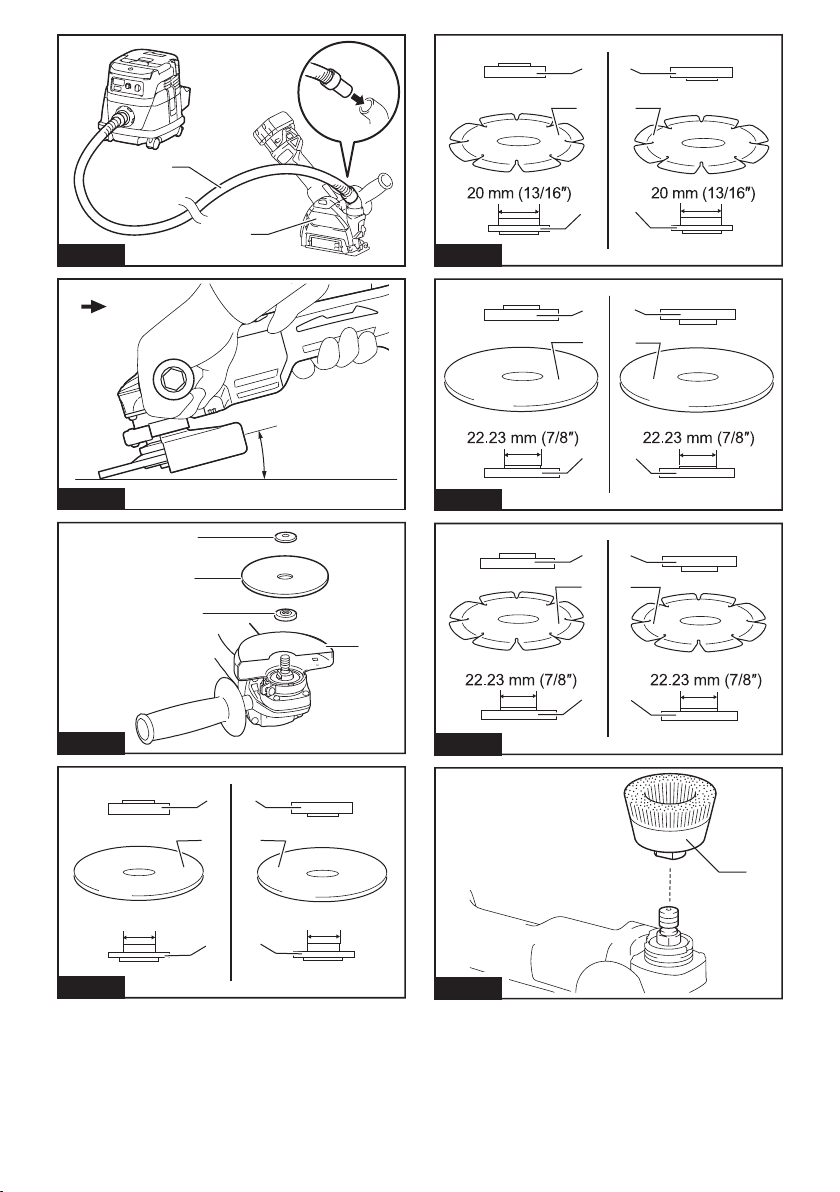
Fig.17
11
23
2
4
4
1
Fig.21
11
23
Fig.18
Fig.19
16 mm (5/8″)
Fig.20
1
2
3
11
23
4
15°
16 mm (5/8″)
4
44
Fig.22
11
23
4
44
Fig.23
1
Fig.24
4
Page 5
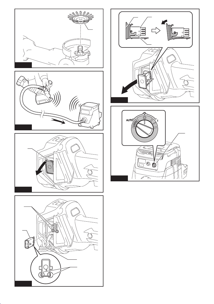
Fig.25
Fig.26
1
3
1
2
Fig.29
1
1
Fig.27
4
1
Fig.28
Fig.30
3
2
5
Page 6
1
Fig.31
1
2
2
1
2
Fig.34
1
Fig.35
Fig.32
Fig.33
1
1
Fig.36
6
Page 7
1
Fig.37
1
2
2
Fig.38
1
2
1
Fig.39
1
2
3
4
5
Fig.40
2
8
3
6
7
9
10
2
12
11
5
7
13
3
14
5
15
3
14
5
Page 8

ENGLISH (Original instructions)
SPECIFICATIONS
Model: DGA417 DGA418
Wheel diameter 100 mm (4″)
Max. wheel thickness 6.4 mm
Spindle thread M10
Rated speed (n) 8,500 min
Overall length 382 mm
Rated voltage D.C. 18 V
Net weight 2.2 - 2.9 kg
Electric brake
Wireless activation function -
Model: DGA467 DGA468
Wheel diameter 115 mm (4-1/2″)
Max. wheel thickness 7.2 mm
Spindle thread M14 or 5/8″ (country specic)
Rated speed (n) 8,500 min
Overall length 382 mm
Rated voltage D.C. 18 V
Net weight 2.4 - 3.1 kg
Electric brake
Wireless activation function -
-1
-1
Model: DGA517 DGA518
Wheel diameter 125 mm (5″)
Max. wheel thickness 7.2 mm
Spindle thread M14 or 5/8″ (country specic)
Rated speed (n) 8,500 min
Overall length 382 mm
Rated voltage D.C. 18 V
Net weight 2.4 - 3.1 kg
Electric brake
Wireless activation function -
-1
• Due to our continuing program of research and development, the specications herein are subject to change
without notice.
• Specications may differ from country to country.
• The weight may differ depending on the attachment(s), including the battery cartridge. The lightest and heaviest combination, according to EPTA-Procedure 01/2014, are shown in the table.
Applicable battery cartridge
BL1815N / BL1820 / BL1820B / BL1830 / BL1830B / BL1840 / BL1840B / BL1850 / BL1850B / BL1860B
• Some of the battery cartridges listed above may not be available depending on your region of residence.
WARNING: Only use the battery cartridges listed above. Use of any other battery cartridges may cause
injury and/or re.
Intended use
The tool is intended for grinding, sanding and cutting of
metal and stone materials without the use of water.
8 ENGLISH
Page 9

Noise
The typical A-weighted noise level determined according to EN60745:
Model Sound pressure
DGA417 80 - 3
DGA418 80 - 3
DGA467 80 - 3
DGA468 80 - 3
DGA517 79 - 3
DGA518 79 - 3
level (LpA) : (dB(A))
The noise level under working may exceed 80 dB (A).
WARNING: Wear ear protection.
Vibration
The vibration total value (tri-axial vector sum) determined according to EN60745:
Work mode: surface grinding with normal side grip
Model Vibration emission (ah, AG) :
DGA417 4.5 1.5
DGA418 4.5 1.5
DGA467 5.5 1.5
DGA468 5.5 1.5
DGA517 6.0 1.5
DGA518 6.0 1.5
Work mode: surface grinding with anti vibration side grip
Model Vibration emission (ah, AG) :
DGA417 4.5 1.5
DGA418 4.5 1.5
DGA467 5.0 1.5
DGA468 5.0 1.5
DGA517 5.5 1.5
DGA518 5.5 1.5
Work mode: disc sanding with normal side grip
Model Vibration emission (a
DGA417 2.5 m/s2 or less 1.5
DGA418 2.5 m/s2 or less 1.5
DGA467 2.5 m/s2 or less 1.5
DGA468 2.5 m/s2 or less 1.5
DGA517 2.5 m/s2 or less 1.5
DGA518 2.5 m/s2 or less 1.5
(m/s2)
(m/s2)
(m/s2)
Sound power level
(LWA) : (dB(A))
Uncertainty (K) : (m/s2)
Uncertainty (K) : (m/s2)
) :
h, DS
Uncertainty (K) : (m/s2)
Uncertainty (K) :
(dB(A))
9 ENGLISH
Page 10

Work mode: disc sanding with anti vibration side grip
Model Vibration emission (a
DGA417 2.5 m/s2 or less 1.5
DGA418 2.5 m/s2 or less 1.5
DGA467 2.5 m/s2 or less 1.5
DGA468 2.5 m/s2 or less 1.5
DGA517 2.5 m/s2 or less 1.5
DGA518 2.5 m/s2 or less 1.5
NOTE: The declared vibration emission value has been measured in accordance with the standard test method
and may be used for comparing one tool with another.
NOTE: The declared vibration emission value may also be used in a preliminary assessment of exposure.
(m/s2)
h, DS
) :
Uncertainty (K) : (m/s2)
WARNING: The vibration emission during actual use of the power tool can differ from the declared emission
value depending on the ways in which the tool is used.
WARNING: Be sure to identify safety measures to protect the operator that are based on an estimation of
exposure in the actual conditions of use (taking account of all parts of the operating cycle such as the times when
the tool is switched off and when it is running idle in addition to the trigger time).
WARNING: The declared vibration emission value is used for main applications of the power tool. However if
the power tool is used for other applications, the vibration emission value may be different.
EC Declaration of Conformity
For European countries only
The EC declaration of conformity is included as Annex A
to this instruction manual.
SAFETY WARNINGS
General power tool safety warnings
WARNING: Read all safety warnings, instruc-
tions, illustrations and specications provided
with this power tool. Failure to follow all instructions
listed below may result in electric shock, re and/or
serious injury.
Save all warnings and instructions for future reference.
The term "power tool" in the warnings refers to your
mains-operated (corded) power tool or battery-operated
(cordless) power tool.
Cordless grinder safety warnings
Safety Warnings Common for Grinding, Sanding,
Wire Brushing, or Abrasive Cutting-Off Operations:
1.
This power tool is intended to function as a
grinder, sander, wire brush or cut-off tool. Read
all safety warnings, instructions, illustrations
and specications provided with this power tool.
Failure to follow all instructions listed below may
result in electric shock, re and/or serious injury.
2.
Operations such as polishing are not recommended to be performed with this power tool.
Operations for which the power tool was not designed
may create a hazard and cause personal injury.
3. Do not use accessories which are not speci-
cally designed and recommended by the tool
manufacturer. Just because the accessory can
be attached to your power tool, it does not assure
safe operation.
4. The rated speed of the accessory must be at
least equal to the maximum speed marked on
the power tool. Accessories running faster than
their rated speed can break and y apart.
5. The outside diameter and the thickness of your
accessory must be within the capacity rating
of your power tool. Incorrectly sized accessories
cannot be adequately guarded or controlled.
6. Threaded mounting of accessories must
match the grinder spindle thread. For acces-
sories mounted by anges, the arbour hole of
the accessory must t the locating diameter
of the ange. Accessories that do not match the
mounting hardware of the power tool will run out of
balance, vibrate excessively and may cause loss
of control.
7.
Do not use a damaged accessory. Before each
use inspect the accessory such as abrasive
wheels for chips and cracks, backing pad for
cracks, tear or excess wear, wire brush for loose
or cracked wires. If power tool or accessory
is dropped, inspect for damage or install an
undamaged accessory. After inspecting and
installing an accessory, position yourself and
bystanders away from the plane of the rotating
accessory and run the power tool at maximum
no-load speed for one minute. Damaged acces-
sories will normally break apart during this test time.
8. Wear personal protective equipment.
Depending on application, use face shield,
safety goggles or safety glasses. As appropriate, wear dust mask, hearing protectors,
gloves and workshop apron capable of stopping small abrasive or workpiece fragments.
The eye protection must be capable of stopping
ying debris generated by various operations.
10 ENGLISH
Page 11

The dust mask or respirator must be capable of
ltrating particles generated by your operation.
Prolonged exposure to high intensity noise may
cause hearing loss.
9. Keep bystanders a safe distance away from
work area. Anyone entering the work area
must wear personal protective equipment.
Fragments of workpiece or of a broken accessory
may y away and cause injury beyond immediate
area of operation.
10. Hold the power tool by insulated gripping
surfaces only, when performing an operation
where the cutting tool may contact hidden
wiring. Contact with a "live" wire will also make
exposed metal parts of the power tool "live" and
could give the operator an electric shock.
11. Never lay the power tool down until the acces-
sory has come to a complete stop. The spinning
accessory may grab the surface and pull the
power tool out of your control.
12. Do not run the power tool while carrying it at
your side. Accidental contact with the spinning
accessory could snag your clothing, pulling the
accessory into your body.
13. Regularly clean the power tool’s air vents. The
motor’s fan will draw the dust inside the housing
and excessive accumulation of powdered metal
may cause electrical hazards.
14. Do not operate the power tool near ammable
materials. Sparks could ignite these materials.
15. Do not use accessories that require liquid
coolants. Using water or other liquid coolants
may result in electrocution or shock.
Kickback and Related Warnings
Kickback is a sudden reaction to a pinched or snagged
rotating wheel, backing pad, brush or any other accessory. Pinching or snagging causes rapid stalling of the
rotating accessory which in turn causes the uncon-
trolled power tool to be forced in the direction opposite
of the accessory’s rotation at the point of the binding.
For example, if an abrasive wheel is snagged or
pinched by the workpiece, the edge of the wheel that is
entering into the pinch point can dig into the surface of
the material causing the wheel to climb out or kick out.
The wheel may either jump toward or away from the
operator, depending on direction of the wheel’s move-
ment at the point of pinching. Abrasive wheels may also
break under these conditions.
Kickback is the result of power tool misuse and/or
incorrect operating procedures or conditions and can be
avoided by taking proper precautions as given below.
1. Maintain a rm grip on the power tool and
position your body and arm to allow you to
resist kickback forces. Always use auxiliary
handle, if provided, for maximum control over
kickback or torque reaction during start-up.
The operator can control torque reactions or kickback forces, if proper precautions are taken.
2. Never place your hand near the rotating acces-
sory. Accessory may kickback over your hand.
3. Do not position your body in the area where
power tool will move if kickback occurs.
Kickback will propel the tool in direction opposite
to the wheel’s movement at the point of snagging.
4. Use special care when working corners, sharp
edges etc. Avoid bouncing and snagging the
accessory. Corners, sharp edges or bouncing
have a tendency to snag the rotating accessory
and cause loss of control or kickback.
5. Do not attach a saw chain woodcarving blade
or toothed saw blade. Such blades create frequent kickback and loss of control.
Safety Warnings Specic for Grinding and Abrasive
Cutting-Off Operations:
1. Use only wheel types that are recommended
for your power tool and the specic guard
designed for the selected wheel. Wheels for
which the power tool was not designed cannot be
adequately guarded and are unsafe.
2. The grinding surface of centre depressed
wheels must be mounted below the plane of
the guard lip. An improperly mounted wheel that
projects through the plane of the guard lip cannot
be adequately protected.
3. The guard must be securely attached to the
power tool and positioned for maximum safety,
so the least amount of wheel is exposed
towards the operator. The guard helps to protect
the operator from broken wheel fragments, accidental contact with wheel and sparks that could
ignite clothing.
4. Wheels must be used only for recommended
applications. For example: do not grind with
the side of cut-off wheel. Abrasive cut-off wheels
are intended for peripheral grinding, side forces
applied to these wheels may cause them to
shatter.
5. Always use undamaged wheel anges that are
of correct size and shape for your selected
wheel. Proper wheel anges support the wheel
thus reducing the possibility of wheel breakage.
Flanges for cut-off wheels may be different from
grinding wheel anges.
6. Do not use worn down wheels from larger
power tools. Wheel intended for larger power tool
is not suitable for the higher speed of a smaller
tool and may burst.
Additional Safety Warnings Specic for Abrasive
Cutting-Off Operations:
1. Do not “jam“ the cut-off wheel or apply excessive pressure. Do not attempt to make an
excessive depth of cut. Overstressing the wheel
increases the loading and susceptibility to twisting
or binding of the wheel in the cut and the possibil-
ity of kickback or wheel breakage.
2. Do not position your body in line with and
behind the rotating wheel. When the wheel, at
the point of operation, is moving away from your
body, the possible kickback may propel the spinning wheel and the power tool directly at you.
3. When wheel is binding or when interrupting
a cut for any reason, switch off the power
tool and hold the power tool motionless until
the wheel comes to a complete stop. Never
attempt to remove the cut-off wheel from the
cut while the wheel is in motion otherwise
kickback may occur. Investigate and take correc-
tive action to eliminate the cause of wheel binding.
11 ENGLISH
Page 12

4. Do not restart the cutting operation in the
workpiece. Let the wheel reach full speed and
carefully re-enter the cut. The wheel may bind,
walk up or kickback if the power tool is restarted in
the workpiece.
5. Support panels or any oversized workpiece to
minimize the risk of wheel pinching and kickback. Large workpieces tend to sag under their
own weight. Supports must be placed under the
workpiece near the line of cut and near the edge
of the workpiece on both sides of the wheel.
6. Use extra caution when making a “pocket cut”
into existing walls or other blind areas. The
protruding wheel may cut gas or water pipes, electrical wiring or objects that can cause kickback.
Safety Warnings Specic for Sanding Operations:
1. Do not use excessively oversized sanding
disc paper. Follow manufacturers recommendations, when selecting sanding paper. Larger
sanding paper extending beyond the sanding
pad presents a laceration hazard and may cause
snagging, tearing of the disc or kickback.
Safety Warnings Specic for Wire Brushing
Operations:
1. Be aware that wire bristles are thrown by the
brush even during ordinary operation. Do not
overstress the wires by applying excessive
load to the brush. The wire bristles can easily
penetrate light clothing and/or skin.
2. If the use of a guard is recommended for wire
brushing, do not allow any interference of the
wire wheel or brush with the guard. Wire wheel
or brush may expand in diameter due to work load
and centrifugal forces.
Additional Safety Warnings:
1. When using depressed centre grinding wheels,
be sure to use only berglass-reinforced
wheels.
2. NEVER USE Stone Cup type wheels with this
grinder. This grinder is not designed for these
types of wheels and the use of such a product
may result in serious personal injury.
3. Be careful not to damage the spindle, the
ange (especially the installing surface) or the
lock nut. Damage to these parts could result in
wheel breakage.
4. Make sure the wheel is not contacting the
workpiece before the switch is turned on.
5. Before using the tool on an actual workpiece,
let it run for a while. Watch for vibration or
wobbling that could indicate poor installation
or a poorly balanced wheel.
6. Use the specied surface of the wheel to per-
form the grinding.
7. Do not leave the tool running. Operate the tool
only when hand-held.
8. Do not touch the workpiece immediately after
operation; it may be extremely hot and could
burn your skin.
9. Observe the instructions of the manufacturer
for correct mounting and use of wheels.
Handle and store wheels with care.
10. Do not use separate reducing bushings or
adaptors to adapt large hole abrasive wheels.
11. Use only anges specied for this tool.
12. For tools intended to be tted with threaded
hole wheel, ensure that the thread in the wheel
is long enough to accept the spindle length.
13. Check that the workpiece is properly
supported.
14. Pay attention that the wheel continues to
rotate after the tool is switched off.
15. If working place is extremely hot and humid,
or badly polluted by conductive dust, use a
short-circuit breaker (30 mA) to assure operator safety.
16. Do not use the tool on any materials containing asbestos.
17. When use cut-off wheel, always work with
the dust collecting wheel guard required by
domestic regulation.
18. Cutting discs must not be subjected to any
lateral pressure.
19. Do not use cloth work gloves during operation.
Fibers from cloth gloves may enter the tool, which
causes tool breakage.
SAVE THESE INSTRUCTIONS.
WARNING: DO NOT let comfort or familiarity
with product (gained from repeated use) replace
strict adherence to safety rules for the subject
product. MISUSE or failure to follow the safety
rules stated in this instruction manual may cause
serious personal injury.
Important safety instructions for
battery cartridge
1.
Before using battery cartridge, read all instructions and cautionary markings on (1) battery charger, (2) battery, and (3) product using battery.
2. Do not disassemble battery cartridge.
3. If operating time has become excessively
shorter, stop operating immediately. It may
result in a risk of overheating, possible burns
and even an explosion.
4. If electrolyte gets into your eyes, rinse them
out with clear water and seek medical attention right away. It may result in loss of your
eyesight.
5. Do not short the battery cartridge:
(1) Do not touch the terminals with any con-
ductive material.
(2) Avoid storing battery cartridge in a con-
tainer with other metal objects such as
nails, coins, etc.
(3) Do not expose battery cartridge to water
or rain.
A battery short can cause a large current
ow, overheating, possible burns and even a
breakdown.
6. Do not store the tool and battery cartridge in
locations where the temperature may reach or
exceed 50 °C (122 °F).
7. Do not incinerate the battery cartridge even if
it is severely damaged or is completely worn
out. The battery cartridge can explode in a re.
12 ENGLISH
Page 13

8. Be careful not to drop or strike battery.
9. Do not use a damaged battery.
10. The contained lithium-ion batteries are subject
to the Dangerous Goods Legislation requirements.
For commercial transports e.g. by third parties,
forwarding agents, special requirement on packaging and labeling must be observed.
For preparation of the item being shipped, consult-
ing an expert for hazardous material is required.
Please also observe possibly more detailed
national regulations.
Tape or mask off open contacts and pack up the
battery in such a manner that it cannot move
around in the packaging.
11. Follow your local regulations relating to dis-
posal of battery.
12. Use the batteries only with the products
specied by Makita. Installing the batteries to
non-compliant products may result in a re, excessive heat, explosion, or leak of electrolyte.
SAVE THESE INSTRUCTIONS.
CAUTION: Only use genuine Makita batteries.
Use of non-genuine Makita batteries, or batteries that
have been altered, may result in the battery bursting
causing res, personal injury and damage. It will
also void the Makita warranty for the Makita tool and
charger.
Tips for maintaining maximum
battery life
1. Charge the battery cartridge before completely
discharged. Always stop tool operation and
charge the battery cartridge when you notice
less tool power.
2. Never recharge a fully charged battery cartridge. Overcharging shortens the battery
service life.
3. Charge the battery cartridge with room temperature at 10 °C - 40 °C (50 °F - 104 °F). Let
a hot battery cartridge cool down before
charging it.
4. Charge the battery cartridge if you do not use
it for a long period (more than six months).
Important safety instructions for
wireless unit
1. Do not disassemble or tamper with the wireless unit.
2. Keep the wireless unit away from young children. If accidentally swallowed, seek medical
attention immediately.
3. Use the wireless unit only with Makita tools.
4. Do not expose the wireless unit to rain or wet
conditions.
5. Do not use the wireless unit in places where
the temperature exceeds 50°C (122°F).
6. Do not operate the wireless unit in places
where medical instruments, such as heart
pace makers are near by.
7. Do not operate the wireless unit in places
where automated devices are near by. If oper-
ated, automated devices may develop malfunction
or error.
8. The wireless unit can produce electromagnetic
elds (EMF) but they are not harmful to the
user.
9. The wireless unit is an accurate instrument. Be
careful not to drop or strike the wireless unit.
10. Avoid touching the terminal of the wireless
unit with bare hands or metallic materials.
11. Always remove the battery on the tool when
installing the wireless unit.
12. When opening the lid of the slot, avoid the
place where dust and water may come into the
slot. Always keep the inlet of the slot clean.
13. Always insert the wireless unit in the correct
direction.
14. Do not press the wireless activation button
on the wireless unit too hard and/or press the
button with an object with a sharp edge.
15. Always close the lid of the slot when
operating.
16. Do not remove the wireless unit from the slot
while the power is being supplied to the tool.
Doing so may cause a malfunction of the wireless
unit.
17. Do not remove the sticker on the wireless unit.
18. Do not put any sticker on the wireless unit.
19. Do not leave the wireless unit in a place where
static electricity or electrical noise could be
generated.
20. Do not leave the wireless unit in a place subject to high heat, such as a car sitting in the
sun.
21. Do not leave the wireless unit in a dusty or
powdery place or in a place corrosive gas
could be generated.
22. Sudden change of the temperature may bedew
the wireless unit. Do not use the wireless unit
until the dew is completely dried.
23. When cleaning the wireless unit, gently wipe
with a dry soft cloth. Do not use benzine, thinner, conductive grease or the like.
24. When storing the wireless unit, keep it in the
supplied case or a static-free container.
25. Do not insert any devices other than Makita
wireless unit into the slot on the tool.
26. Do not use the tool with the lid of the slot damaged. Water, dust, and dirt come into the slot may
cause malfunction.
27. Do not pull and/or twist the lid of the slot more
than necessary. Restore the lid if it comes off
from the tool.
28. Replace the lid of the slot if it is lost or
damaged.
SAVE THESE INSTRUCTIONS.
13 ENGLISH
Page 14
FUNCTIONAL
DESCRIPTION
CAUTION: Always be sure that the tool is
switched off and the battery cartridge is removed
before adjusting or checking function on the tool.
Installing or removing battery cartridge
CAUTION: Always switch off the tool before
installing or removing of the battery cartridge.
CAUTION:
rmly when installing or removing battery cartridge.
Failure to hold the tool and the battery cartridge rmly may
cause them to slip off your hands and result in damage to
the tool and battery cartridge and a personal injury.
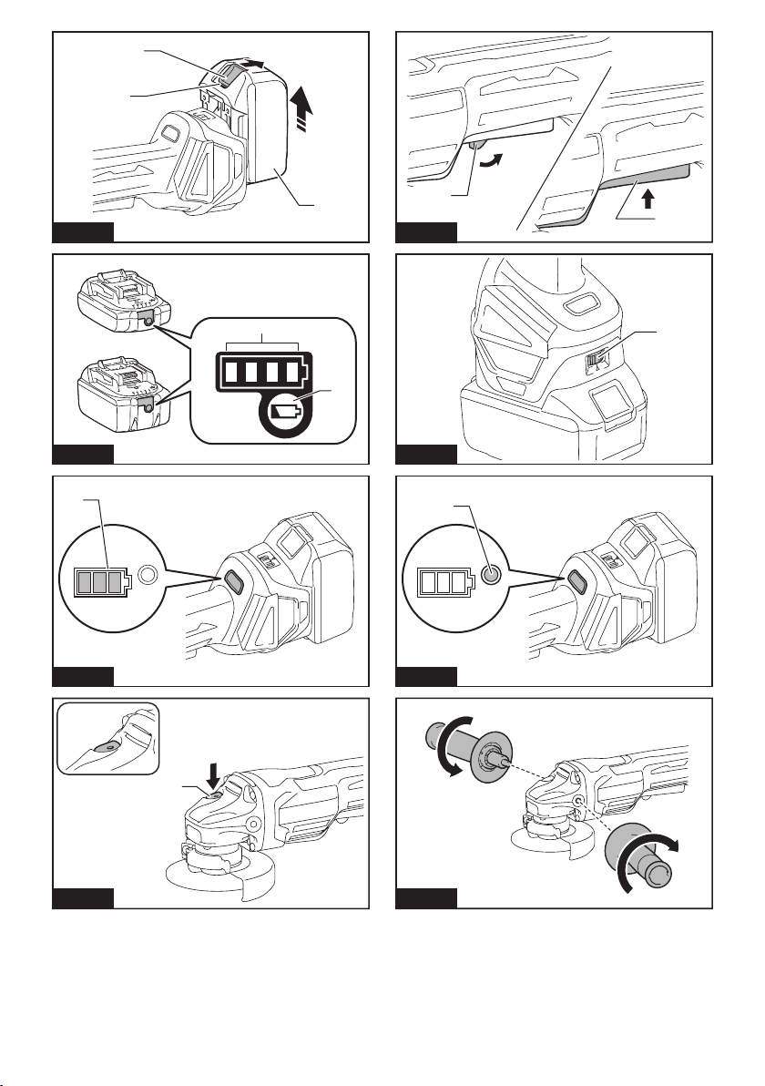
► Fig.1: 1. Red indicator 2. Button 3. Battery cartridge
To remove the battery cartridge, slide it from the tool
while sliding the button on the front of the cartridge.
To install the battery cartridge, align the tongue on the
battery cartridge with the groove in the housing and slip
it into place. Insert it all the way until it locks in place
with a little click. If you can see the red indicator on the
upper side of the button, it is not locked completely.
CAUTION:
until the red indicator cannot be seen. If not, it may accidentally
fall out of the tool, causing injury to you or someone around you.
CAUTION: Do not install the battery cartridge
forcibly. If the cartridge does not slide in easily, it is
not being inserted correctly.
Indicating the remaining battery capacity
Only for battery cartridges with the indicator
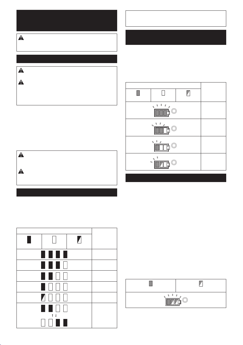
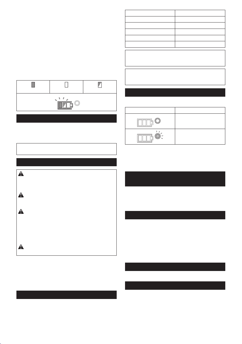
► Fig.2: 1. Indicator lamps 2. Check button
Press the check button on the battery cartridge to indi-
cate the remaining battery capacity. The indicator lamps
light up for a few seconds.
Lighted Off Blinking
Hold the tool and the battery cartridge
Always install the battery cartridge fully
Indicator lamps Remaining
capacity
75% to 100%
50% to 75%
25% to 50%
NOTE: Depending on the conditions of use and the
ambient temperature, the indication may differ slightly
from the actual capacity.
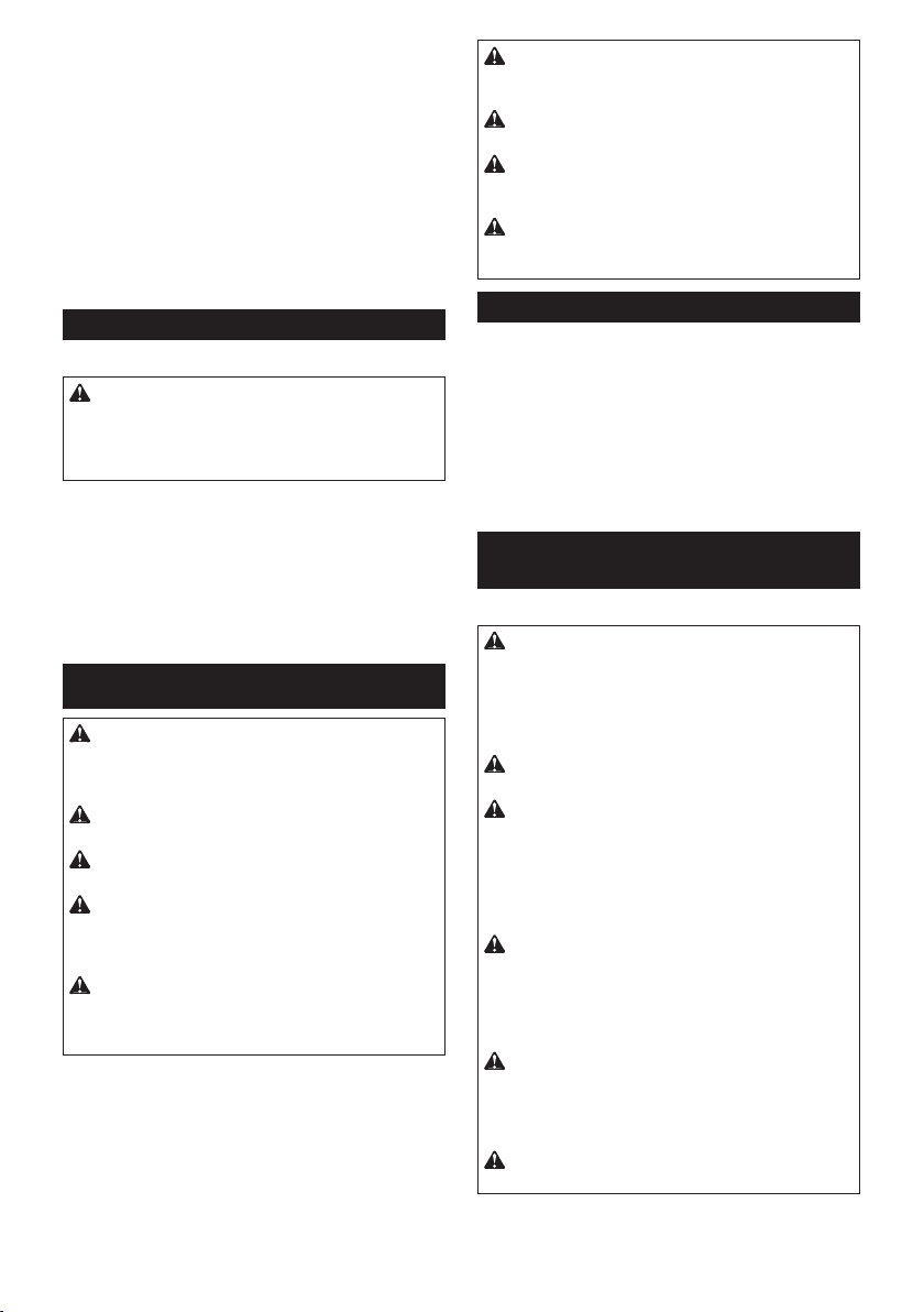
Indicating the remaining battery
capacity
Country specic
When you turn the tool on, the battery indicator shows
the remaining battery capacity.
► Fig.3: 1. Battery indicator
The remaining battery capacity is shown as the follow-
ing table.
Battery indicator status Remaining
On
Off
Blinking
battery
capacity
50% to 100%
20% to 50%
0% to 20%
Charge the
battery
Tool / battery protection system
The tool is equipped with a tool/battery protection system. This system automatically cuts off power to the
motor to extend tool and battery life. The tool will automatically stop during operation if the tool or battery is
placed under one of the following conditions:
Overload protection
When the tool is operated in a manner that causes it to
draw an abnormally high current, the tool automatically
stops without any indication. In this situation, turn the
tool off and stop the application that caused the tool to
become overloaded. Then turn the tool on to restart.
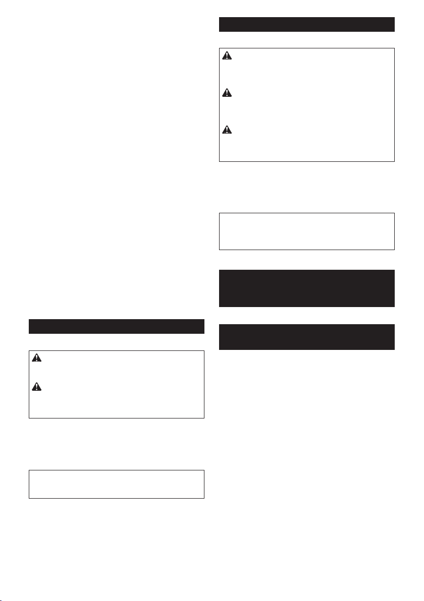
Overheat protection
When the tool is overheated, the tool stops automati-
cally and the battery indicator shows following state. In
this situation, let the tool cool before turning the tool on
again.
0% to 25%
Charge the
battery.
The battery
may have
malfunctioned.
On
If the tool does not start, the battery may be overheated.
In this situation, let the battery cool before starting the
tool again.
14 ENGLISH
Blinking
Page 15
Overdischarge protection
When the battery capacity is not enough, the tool stops
automatically. In this case, remove the battery from the
tool and charge the battery.
Releasing protection lock
When the protection system works repeatedly, the tool
is locked and the battery indicator shows the following
state.
In this situation, the tool does not start even if turning
the tool off and on. To release the protection lock,
remove the battery, set it to the battery charger and wait
until the charging nishes.
On
Off
Blinking
Shaft lock
Press the shaft lock to prevent spindle rotation when
installing or removing accessories.
► Fig.4: 1. Shaft lock
NOTICE: Never actuate the shaft lock when the
spindle is moving. The tool may be damaged.
Switch action
CAUTION: Before installing the battery car-
tridge into the tool, always check to see that the
switch lever actuates properly and returns to the
"OFF" position when released.
CAUTION: Do not pull the switch lever hard
without pulling the lock-off lever. This can cause
switch breakage.
CAUTION: For your safety, this tool is
equipped with lock-off lever which prevents the
tool from unintended starting. NEVER use the tool
if it runs when you simply pull the switch trigger
without pulling the lock-off lever. Return the tool
to our authorized service center for proper repairs
BEFORE further usage.
CAUTION: NEVER tape down or defeat pur-
pose and function of lock-off lever.
To prevent the switch lever from being accidentally
pulled, a lock-off lever is provided.
To start the tool, pull the lock-off lever toward the operator and then pull the switch lever.
To stop the tool, release the switch lever.
► Fig.5: 1. Lock-off lever 2. Switch lever
Speed adjusting dial
The rotation speed of the tool can be changed by turning the speed adjusting dial. The table below shows
the number on the dial and the corresponding rotation
speed.
► Fig.6: 1. Speed adjusting dial
Number Speed
1 3,000 min
2 4,500 min
3 6,000 min
4 7,500 min
5 8,500 min
-1
-1
-1
-1
-1
NOTICE: If the tool is operated continuously at
low speed for a long time, the motor will get overloaded, resulting in tool malfunction.
NOTICE: When changing the speed dial from "5"
to "1", turn the dial counterclockwise. Do not turn
the dial clockwise forcibly.
Automatic speed change function
► Fig.7: 1. Mode indicator
Mode indicator status Operation mode
High speed mode
High torque mode
This tool has "high speed mode" and "high torque
mode". It automatically changes operation mode
depending on the work load. When mode indicator
lights up during operation, the tool is in high torque
mode.
Accidental re-start preventive
function
Even if installing the battery cartridge while pulling the
switch lever, the tool does not start.
To start the tool, rst release the switch lever. Then pull
the lock-off lever, and pull the switch lever.
Electronic torque control function
The tool electronically detects situations where the
wheel or accessory may be at risk to be bound. In the
situation, the tool is automatically shut off to prevent
further rotation of the spindle (it does not prevent
kickback).
To restart the tool, switch off the tool rst, remove the
cause of sudden drop in the rotation speed, and then
turn the tool on.
Soft start feature
Soft start feature reduces starting reaction.
Electric brake
Electric brake is activated after the tool is switched off.
The brake does not work when the power supply is shut
down, such as the battery is removed accidentally, with
the switch still on.
15 ENGLISH
Page 16

ASSEMBLY
CAUTION: Always be sure that the tool is
switched off and the battery cartridge is removed
before adjusting or checking function on the tool.
Installing side grip (handle)
CAUTION: Always be sure that the side grip is
installed securely before operation.
Screw the side grip securely on the position of the tool
as shown in the gure.
► Fig.8
Installing or removing wheel guard
(For depressed center wheel, ap disc,
ex wheel, wire wheel brush / abrasive
cut-off wheel, diamond wheel)
WARNING:
ap disc, ex wheel or wire wheel brush, the wheel
guard must be tted on the tool so that the closed side
of the guard always points toward the operator.
WARNING: When using an abrasive cut-off
/ diamond wheel, be sure to use only the special
wheel guard designed for use with cut-off wheels.
(In some European countries, when using a diamond
wheel, the ordinary guard can be used. Follow the
regulations in your country.)
For tool with locking screw type
wheel guard
Mount the wheel guard with the protrusions on the
wheel guard band aligned with the notches on the bear-
ing box. Then rotate the wheel guard to such an angle
that it can protect the operator according to work. Be
sure to tighten the screw securely.
To remove wheel guard, follow the installation proce-
dure in reverse.
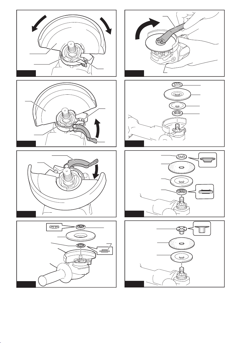
► Fig.9: 1. Wheel guard 2. Bearing box 3. Screw
For tool with clamp lever type wheel
guard
Loosen the screw, and then pull the lever in the direction
of the arrow. Mount the wheel guard with the protrusions
on the wheel guard band aligned with the notches on
the bearing box. Then rotate the wheel guard to such an
angle that it can protect the operator according to work.
► Fig.10: 1. Wheel guard 2. Bearing box 3. Screw
Pull the lever in direction of the arrow. Then tighten the
wheel guard with fastening the screw. Be sure to tighten
the screw securely. The setting angle of the wheel
guard can be adjusted with the lever.
► Fig.11: 1. Screw 2. Lever
To remove wheel guard, follow the installation proce-
dure in reverse.
When using a depressed center wheel,
4. Lever
Installing or removing depressed
center wheel or ap disc
Optional accessory
WARNING: When using a depressed center
wheel or ap disc, the wheel guard must be tted
on the tool so that the closed side of the guard
always points toward the operator.
CAUTION: Make sure that the mounting part
of the inner ange ts into the inner diameter of
the depressed center wheel / ap disc perfectly.
Mounting the inner ange on the wrong side may
result in the dangerous vibration.
Mount the inner ange onto the spindle.
Make sure to t the dented part of the inner ange onto
the straight part at the bottom of the spindle.
Fit the depressed center wheel / ap disc on the inner
ange and screw the lock nut onto the spindle.
► Fig.12: 1. Lock nut 2. Depressed center wheel
3. Inner ange 4. Mounting part
To tighten the lock nut, press the shaft lock rmly so
that the spindle cannot revolve, then use the lock nut
wrench and securely tighten clockwise.
► Fig.13: 1. Lock nut wrench 2. Shaft lock
To remove the wheel, follow the installation procedure
in reverse.
Installing or removing ex wheel
Optional accessory
WARNING: Always use supplied guard when
ex wheel is on tool. Wheel can shatter during use
and guard helps to reduce chances of personal injury.
► Fig.14: 1. Lock nut 2. Flex wheel 3. Back up pad
4. Inner ange
Follow instructions for depressed center wheel but also
use back up pad over wheel. See order of assembly on
accessories page in this manual.
Installing or removing abrasive disc
Optional accessory
NOTE: Use sander accessories specied in this manual. These must be purchased separately.
For 100 mm (4″) model
► Fig.15: 1. Sanding lock nut 2. Abrasive disc
3. Rubber pad 4. Inner ange
1. Mount the inner ange onto the spindle.
2. Mount the rubber pad onto the spindle.
3. Fit the disc on the rubber pad and screw the sand-
ing lock nut onto the spindle.
4. Hold the spindle with the shaft lock, and securely
tighten the sanding lock nut clockwise with the lock nut
wrench.
To remove the disc, follow the installation procedure in
reverse.
16 ENGLISH
Page 17
For 115 mm (4 - 1/2″) / 125 mm (5″)
model
► Fig.16: 1. Sanding lock nut 2. Abrasive disc
3. Rubber pad
1. Mount the rubber pad onto the spindle.
2. Fit the disc on the rubber pad and screw the sand-
ing lock nut onto the spindle.
3. Hold the spindle with the shaft lock, and securely
tighten the sanding lock nut clockwise with the lock nut
wrench.
To remove the disc, follow the installation procedure in
reverse.
Connecting a vacuum cleaner
Optional accessory
WARNING: Never vacuum metal particles
created by grinding/cutting/sanding operation.
Metal particles created by such operation are so hot
that they ignite dust and the lter inside the vacuum
cleaner.
To avoid dusty environment caused by masonry cutting, use a dust collecting wheel guard and a vacuum
cleaner.
Refer to the instruction manual attached to the dust
collecting wheel guard for assembling and using it.
► Fig.17: 1. Dust collecting wheel guard 2. Hose of
the vacuum cleaner
OPERATION
WARNING: It should never be necessary to
force the tool. The weight of the tool applies ade-
quate pressure. Forcing and excessive pressure
could cause dangerous wheel breakage.
WARNING: ALWAYS replace wheel if tool is
dropped while grinding.
WARNING: NEVER bang or hit grinding disc
or wheel onto work.
WARNING: Avoid bouncing and snagging
the wheel, especially when working corners,
sharp edges etc. This can cause loss of control and
kickback.
WARNING: NEVER use tool with wood cutting
blades and other saw blades. Such blades when
used on a grinder frequently kick and cause loss of
control leading to personal injury.
CAUTION: Never switch on the tool when it
is in contact with the workpiece, it may cause an
injury to operator.
CAUTION: Always wear safety goggles or a
face shield during operation.
CAUTION: After operation, always switch off
the tool and wait until the wheel has come to a
complete stop before putting the tool down.
CAUTION: ALWAYS hold the tool rmly with
one hand on housing and the other on the side
grip (handle).
Grinding and sanding operation
► Fig.18
Turn the tool on and then apply the wheel or disc to the
workpiece.
In general, keep the edge of the wheel or disc at an
angle of about 15° to the workpiece surface.
During the break-in period with a new wheel, do not
work the grinder in forward direction or it may cut into
the workpiece. Once the edge of the wheel has been
rounded off by use, the wheel may be worked in both
forward and backward direction.
Operation with abrasive cut-off /
diamond wheel
Optional accessory
WARNING: When using an abrasive cut-off
/ diamond wheel, be sure to use only the special
wheel guard designed for use with cut-off wheels.
(In some European countries, when using a diamond
wheel, the ordinary guard can be used. Follow the
regulations in your country.)
WARNING: NEVER use cut-off wheel for side
grinding.
WARNING: Do not "jam" the wheel or apply
excessive pressure. Do not attempt to make an
excessive depth of cut. Overstressing the wheel
increases the loading and susceptibility to twisting
or binding of the wheel in the cut and the possibility
of kickback, wheel breakage and overheating of the
motor may occur.
WARNING: Do not start the cutting operation
in the workpiece. Let the wheel reach full speed
and carefully enter into the cut moving the tool
forward over the workpiece surface. The wheel
may bind, walk up or kickback if the power tool is
started in the workpiece.
WARNING: During cutting operations, never
change the angle of the wheel. Placing side pres-
sure on the cut-off wheel (as in grinding) will cause
the wheel to crack and break, causing serious per-
sonal injury.
WARNING: A diamond wheel shall be oper-
ated perpendicular to the material being cut.
17 ENGLISH
Page 18
► Fig.19: 1. Lock nut 2. Abrasive cut-off wheel / dia-
mond wheel 3. Inner ange 4. Wheel guard
for abrasive cut-off wheel / diamond wheel
As for the installation, follow the instructions for
depressed center wheel.
The direction for mounting the lock nut and the
inner ange varies by wheel type and thickness.
Refer to the following gures.
For 100 mm (4″) model
When installing the abrasive cut-off wheel:
► Fig.20: 1. Lock nut 2. Abrasive cut-off wheel
(Thinner than 4mm (5/32")) 3. Abrasive cutoff wheel (4mm (5/32") or thicker) 4. Inner
ange
When installing the diamond wheel:
► Fig.21: 1. Lock nut 2. Diamond wheel (Thinner
than 4mm (5/32″)) 3. Diamond wheel (4mm
(5/32″) or thicker) 4. Inner ange
For 115 mm (4 - 1/2″) / 125 mm (5″)
model
When installing the abrasive cut-off wheel:
► Fig.22: 1. Lock nut 2. Abrasive cut-off wheel
(Thinner than 4mm (5/32")) 3. Abrasive cutoff wheel (4mm (5/32") or thicker) 4. Inner
ange
When installing the diamond wheel:
► Fig.23: 1. Lock nut 2. Diamond wheel (Thinner
than 4mm (5/32″)) 3. Diamond wheel (4mm
(5/32″) or thicker) 4. Inner ange
Operation with wire cup brush
Optional accessory
CAUTION: Check operation of brush by run-
ning tool with no load, insuring that no one is in
front of or in line with brush.
CAUTION: Do not use brush that is damaged,
or which is out of balance. Use of damaged brush
could increase potential for injury from contact with
broken brush wires.
► Fig.24: 1. Wire cup brush
Remove the battery cartridge from the tool and place it
upside down allowing easy access to spindle.
Remove any accessories on spindle. Thread wire cup
brush onto spindle and tighten with supplied wrench.
NOTICE: Avoid applying too much pressure
which causes over bending of wires when using
brush. It may lead to premature breakage.
Operation with wire wheel brush
Optional accessory
CAUTION: Check operation of wire wheel
brush by running tool with no load, insuring that
no one is in front of or in line with the wire wheel
brush.
CAUTION: Do not use wire wheel brush that
is damaged, or which is out of balance. Use of
damaged wire wheel brush could increase potential
for injury from contact with broken wires.
CAUTION: ALWAYS use guard with wire
wheel brushes, assuring diameter of wheel ts
inside guard. Wheel can shatter during use and
guard helps to reduce chances of personal injury.
► Fig.25: 1. Wire wheel brush
Remove the battery cartridge from the tool and place it
upside down allowing easy access to spindle.
Remove any accessories on spindle. Thread wire wheel
brush onto spindle and tighten with the wrenches.
NOTICE: Avoid applying too much pressure
which causes over bending of wires when
using wire wheel brush. It may lead to premature
breakage.
WIRELESS ACTIVATION
FUNCTION
For DGA418/DGA468/DGA518 only
What you can do with the wireless
activation function
The wireless activation function enables clean and comfortable operation. By connecting a supported vacuum
cleaner to the tool, you can run the vacuum cleaner
automatically along with the switch operation of the tool.
► Fig.26
To use the wireless activation function, prepare following items:
• A wireless unit
• A vacuum cleaner which supports the wireless
activation function
The overview of the wireless activation function
setting is as follows. Refer to each section for detail
procedures.
1. Installing the wireless unit
2. Tool registration for the vacuum cleaner
3. Starting the wireless activation function
18 ENGLISH
Page 19

Installing the wireless unit
CAUTION: Place the tool on a at and stable
surface when installing the wireless unit.
NOTICE: Clean the dust and dirt on the tool
before installing the wireless unit. Dust or dirt
may cause malfunction if it comes into the slot of the
wireless unit.
NOTICE: To prevent the malfunction caused by
static, touch a static discharging material, such
as a metal part of the tool, before picking up the
wireless unit.
NOTICE: When installing the wireless unit,
always be sure that the wireless unit is inserted
in the correct direction and the lid is completely
closed.
1. Open the lid on the tool as shown in the gure.
► Fig.27: 1. Lid
2. Insert the wireless unit to the slot and then close
the lid.
When inserting the wireless unit, align the projections
with the recessed portions on the slot.
► Fig.28: 1. Wireless unit 2. Projection 3. Lid
4. Recessed portion
When removing the wireless unit, open the lid slowly.
The hooks on the back of the lid will lift the wireless unit
as you pull up the lid.
► Fig.29: 1. Wireless unit 2. Hook 3. Lid
After removing the wireless unit, keep it in the supplied
case or a static-free container.
NOTICE: Always use the hooks on the back of
the lid when removing the wireless unit. If the
hooks do not catch the wireless unit, close the lid
completely and open it slowly again.
Tool registration for the vacuum
cleaner
NOTE: A Makita vacuum cleaner supporting the
wireless activation function is required for the tool
registration.
NOTE: Finish installing the wireless unit to the tool
before starting the tool registration.
NOTE: During the tool registration, do not pull the
switch trigger or turn on the power switch on the
vacuum cleaner.
NOTE: Refer to the instruction manual of the vacuum
cleaner, too.
If you wish to activate the vacuum cleaner along with
the switch operation of the tool, nish the tool registra-
tion beforehand.
1. Install the batteries to the vacuum cleaner and the
tool.
2. Set the stand-by switch on the vacuum cleaner to
"AUTO".
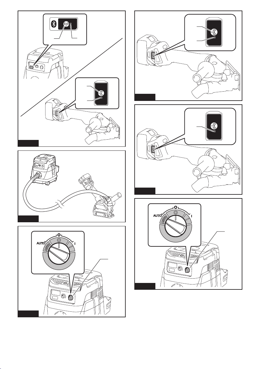
► Fig.30: 1. Stand-by switch
3. Press the wireless activation button on the vac-
uum cleaner for 3 seconds until the wireless activation
lamp blinks in green. And then press the wireless activation button on the tool in the same way.
► Fig.31: 1. Wireless activation button 2. Wireless
If the vacuum cleaner and the tool are linked success-
fully, the wireless activation lamps will light up in green
for 2 seconds and start blinking in blue.
NOTE: The wireless activation lamps nish blinking
in green after 20 seconds elapsed. Press the wireless
activation button on the tool while the wireless activation lamp on the cleaner is blinking. If the wireless
activation lamp does not blink in green, push the wire-
less activation button briey and hold it down again.
NOTE: When performing two or more tool registra-
tions for one vacuum cleaner, nish the tool registration one by one.
activation lamp
Starting the wireless activation
function
NOTE: Finish the tool registration for the vacuum
cleaner prior to the wireless activation.
NOTE: Refer to the instruction manual of the vacuum
cleaner, too.
After registering a tool to the vacuum cleaner, the
vacuum cleaner will automatically runs along with the
switch operation of the tool.
1. Install the wireless unit to the tool.
Connect the hose of the vacuum cleaner with the tool.
2.
► Fig.32
3. Set the stand-by switch on the vacuum cleaner to
"AUTO".
► Fig.33: 1. Stand-by switch
4. Push the wireless activation button on the tool
briey. The wireless activation lamp will blink in blue.
► Fig.34: 1. Wireless activation button 2. Wireless
5. Pull the switch trigger of the tool. Check if the
vacuum cleaner runs while the switch trigger is being
pulled.
To stop the wireless activation of the vacuum cleaner,
push the wireless activation button on the tool.
NOTE: The wireless activation lamp on the tool will
stop blinking in blue when there is no operation for
2 hours. In this case, set the stand-by switch on the
vacuum cleaner to "AUTO" and push the wireless
activation button on the tool again.
NOTE: The vacuum cleaner starts/stops with a delay.
There is a time lag when the vacuum cleaner detects
a switch operation of the tool.
NOTE: The transmission distance of the wireless unit
may vary depending on the location and surrounding
circumstances.
NOTE: When two or more tools are registered to one
vacuum cleaner, the vacuum cleaner may start running even if you don't pull the switch trigger because
an other user is using the wireless activation function.
19 ENGLISH
activation lamp
Page 20
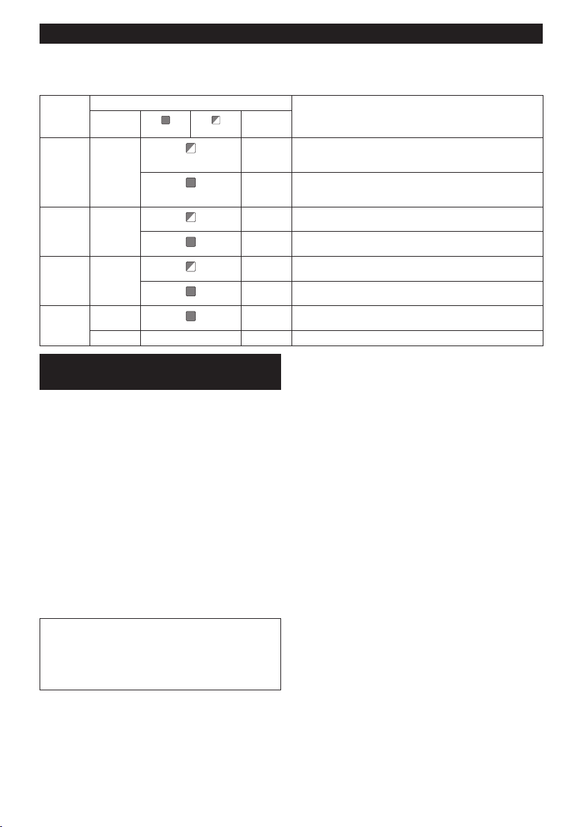
Description of the wireless activation lamp status
► Fig.35: 1. Wireless activation lamp
The wireless activation lamp shows the status of the wireless activation function. Refer to the table below for the
meaning of the lamp status.
Status Wireless activation lamp Description
Duration
2 hours The wireless activation of the vacuum cleaner is available. The
the tool is
running.
20 seconds Ready for the tool registration. Waiting for the registration by the
2 seconds The tool registration has been nished. The wireless activation
20 seconds Ready for the cancellation of the tool registration. Waiting for the
2 seconds The cancellation of the tool registration has been nished. The
3 seconds The power is supplied to the wireless unit and the wireless activa-
lamp will automatically turn off when no operation is performed
for 2 hours.
When
The wireless activation of the vacuum cleaner is available and the
tool is running.
vacuum cleaner.
lamp will start blinking in blue.
cancellation by the vacuum cleaner.
wireless activation lamp will start blinking in blue.
tion function is starting up.
Standby Blue
Tool
registration
Cancelling
tool
registration
Others Red
Color
Green
Red
Off - - The wireless activation of the vacuum cleaner is stopped.
On
Blinking
Cancelling tool registration for the
vacuum cleaner
Perform the following procedure when cancelling the
tool registration for the vacuum cleaner.
1. Install the batteries to the vacuum cleaner and the
tool.
2. Set the stand-by switch on the vacuum cleaner to
"AUTO".
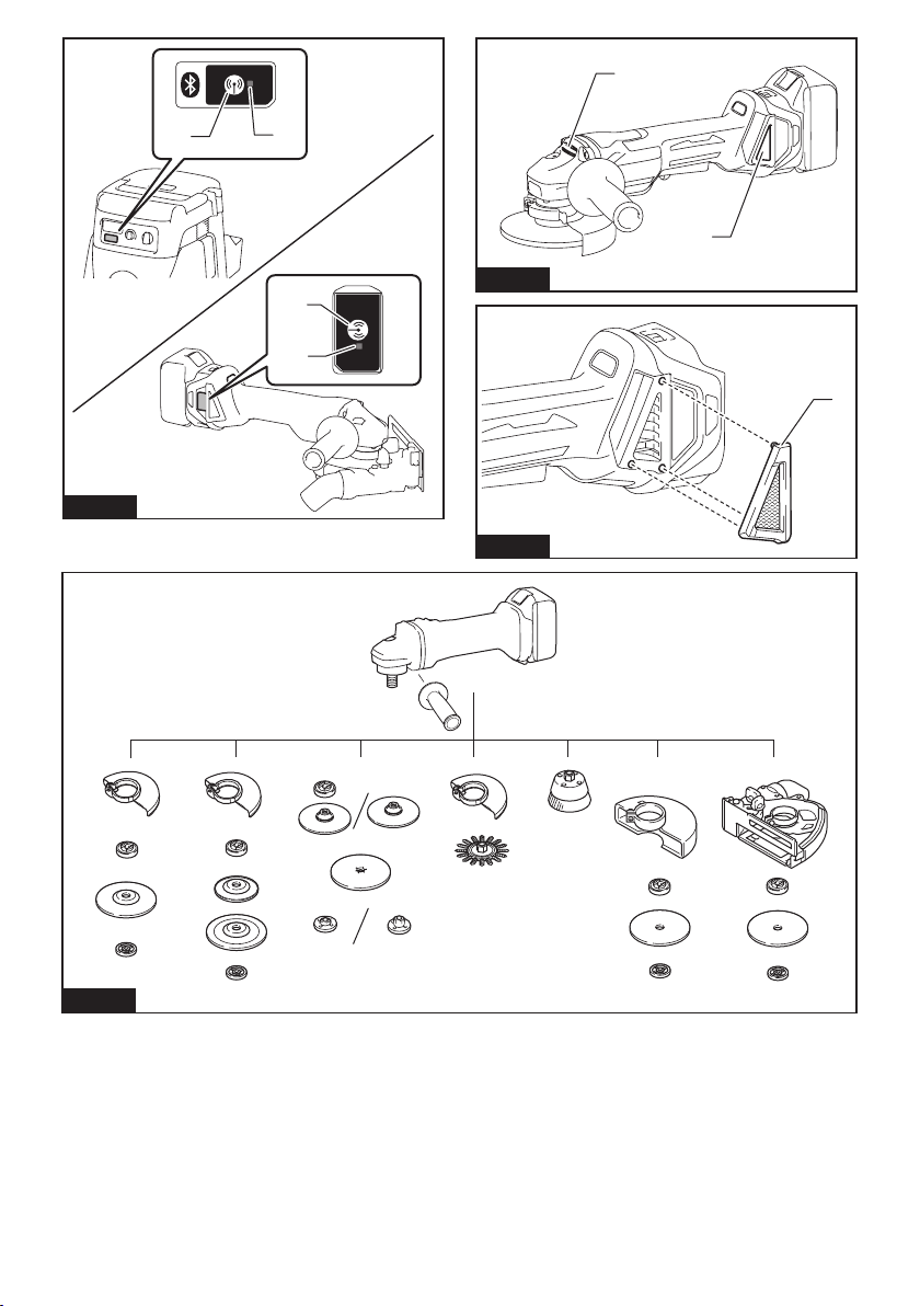
► Fig.36: 1. Stand-by switch
3. Press the wireless activation button on the vac-
uum cleaner for 6 seconds. The wireless activation
lamp blinks in green and then become red. After that,
press the wireless activation button on the tool in the
same way.
► Fig.37: 1. Wireless activation button 2. Wireless
If the cancellation is performed successfully, the wire-
less activation lamps will light up in red for 2 seconds
and start blinking in blue.
NOTE: The wireless activation lamps nish blinking in
red after 20 seconds elapsed. Press the wireless activation button on the tool while the wireless activation
lamp on the cleaner is blinking. If the wireless activation lamp does not blink in red, push the wireless
activation button briey and hold it down again.
activation lamp
20 ENGLISH
Page 21

Troubleshooting for wireless activation function
Before asking for repairs, conduct your own inspection rst. If you nd a problem that is not explained in the manual,
do not attempt to dismantle the tool. Instead, ask Makita Authorized Service Centers, always using Makita replace-
ment parts for repairs.
State of abnormality Probable cause (malfunction) Remedy
The wireless activation lamp does
not light/blink.
Cannot nish tool registration / cancelling tool registration successfully.
The wireless unit is not installed into
the tool.
The wireless unit is improperly installed
into the tool.
The terminal of the wireless unit and/or
the slot is dirty.
The wireless activation button on the
tool has not been pushed.
The stand-by switch on the vacuum
cleaner is not set to "AUTO".
No power supply Supply the power to the tool and the vacuum
The wireless unit is not installed into
the tool.
The wireless unit is improperly installed
into the tool.
The terminal of the wireless unit and/or
the slot is dirty.
The stand-by switch on the vacuum
cleaner is not set to "AUTO".
No power supply Supply the power to the tool and the vacuum
Incorrect operation Push the wireless activation button briey and
The tool and vacuum cleaner is away
from each other (out of the transmission
range).
Before nishing the tool registration/
cancellation;
- the switch trigger on the tool is pulled
or;
- the power button on the vacuum
cleaner is turned on.
The tool registration procedures for the
tool or vacuum cleaner has not nished.
Radio disturbance by other appliances
which generate high-intensity radio
waves.
Install the wireless unit correctly.
Gently wipe off dust and dirt on the terminal of the
wireless unit and clean the slot.
Push the wireless activation button on the tool
briey.
Set the stand-by switch on the vacuum cleaner to
"AUTO".
cleaner.
Install the wireless unit correctly.
Gently wipe off dust and dirt on the terminal of the
wireless unit and clean the slot.
Set the stand-by switch on the vacuum cleaner to
"AUTO".
cleaner.
perform the tool registration/cancellation procedures
again.
Get the tool and vacuum cleaner closer to each
other. The maximum transmission distance is
approximately 10 m however it may vary according
to the circumstances.
Push the wireless activation button briey and
perform the tool registration/cancellation procedures
again.
Perform the tool registration procedures for both the
tool and the vacuum cleaner at the same timing.
Keep the tool and vacuum cleaner away from the
appliances such as Wi-Fi devices and microwave
ovens.
21 ENGLISH
Page 22

State of abnormality Probable cause (malfunction) Remedy
The vacuum cleaner does not run
along with the switch operation of
the tool.
The vacuum cleaner runs while the
tool's switch trigger is not pulled.
The wireless unit is not installed into
the tool.
The wireless unit is improperly installed
into the tool.
The terminal of the wireless unit and/or
the slot is dirty.
The wireless activation button on the
tool has not been pushed.
The stand-by switch on the vacuum
cleaner is not set to "AUTO".
More than 10 tools are registered to the
vacuum cleaner.
The vacuum cleaner erased all tool
registrations.
No power supply Supply the power to the tool and the vacuum
The tool and vacuum cleaner is away
from each other (out of the transmission
range).
Radio disturbance by other appliances
which generate high-intensity radio
waves.
Other users are using the wireless
activation of the vacuum cleaner with
their tools.
Install the wireless unit correctly.
Gently wipe off dust and dirt on the terminal of the
wireless unit and clean the slot.
Push the wireless activation button briey and make
sure that the wireless activation lamp is blinking
in blue.
Set the stand-by switch on the vacuum cleaner to
"AUTO".
Perform the tool registration again.
If more than 10 tools are registered to the vacuum
cleaner, the tool registered earliest will be cancelled
automatically.
Perform the tool registration again.
cleaner.
Get the tool and vacuum cleaner closer each other.
The maximum transmission distance is approximately 10 m however it may vary according to the
circumstances.
Keep the tool and vacuum cleaner away from the
appliances such as Wi-Fi devices and microwave
ovens.
Turn off the wireless activation button of the other
tools or cancel the tool registration of the other
tools.
MAINTENANCE
CAUTION: Always be sure that the tool is
switched off and the battery cartridge is removed
before attempting to perform inspection or
maintenance.
NOTICE: Never use gasoline, benzine, thinner,
alcohol or the like. Discoloration, deformation or
cracks may result.
Air vent cleaning
The tool and its air vents have to be kept clean.
Regularly clean the tool's air vents or whenever the
vents start to become obstructed.
► Fig.38: 1. Exhaust vent 2. Inhalation vent
Remove the dust cover from inhalation vent and clean it
for smooth air circulation.
► Fig.39: 1. Dust cover
NOTICE: Clean out the dust cover when it is
clogged with dust or foreign matters. Continuing
operation with a clogged dust cover may damage the
tool.
22 ENGLISH
Page 23

OPTIONAL ACCESSORIES
CAUTION: These accessories or attachments are recommended for use with your Makita tool spec-
ied in this manual. The use of any other accessories or attachments might present a risk of injury to persons.
Only use accessory or attachment for its stated purpose.
If you need any assistance for more details regarding these accessories, ask your local Makita Service Center.
• Makita genuine battery and charger
• Wireless unit (For models with wireless activation function)
► Fig.40
- 100 mm (4″) model 115 mm (4-1/2″) model 125 mm (5″) model
1 Grip 36
2 Wheel Guard (for grinding wheel)
3 Inner ange
4 Depressed center wheel / Flap disc
5 Lock nut
6 Back up pad
7 Flex wheel
8 Inner ange and rubber pad 76 Rubber pad 100 Rubber pad 115
9 Abrasive disc
10 Sanding lock nut
11 Wire wheel brush
12 Wire cup brush
13 Wheel Guard (for cut-off wheel) *1
14 Abrasive cut-off wheel / Diamond wheel
15 Dust collecting wheel guard
- Lock nut wrench
NOTE: *1 In some European countries, when using a diamond wheel, the ordinary guard can be used instead of the
special guard covering the both side of the wheel. Follow the regulations in your country.
NOTE: Some items in the list may be included in the tool package as standard accessories. They may differ from
country to country.
23 ENGLISH
Page 24

FRANÇAIS (Instructions originales)
SPÉCIFICATIONS
Modèle : DGA417 DGA418
Diamètre de meule 100 mm (4″)
Épaisseur max. de la meule 6,4 mm
Filetage de l’axe M10
Vitesse nominale (n) 8 500 min
Longueur totale 382 mm
Tension nominale 18 V CC
Poids net 2,2 à 2,9 kg
Frein électrique
Fonction d’activation sans l -
Modèle : DGA467 DGA468
Diamètre de meule 115 mm (4-1/2″)
Épaisseur max. de la meule 7,2 mm
Filetage de l’axe M14 ou 5/8″ (selon le pays)
Vitesse nominale (n) 8 500 min
Longueur totale 382 mm
Tension nominale 18 V CC
Poids net 2,4 à 3,1 kg
Frein électrique
Fonction d’activation sans l -
-1
-1
Modèle : DGA517 DGA518
Diamètre de meule 125 mm (5″)
Épaisseur max. de la meule 7,2 mm
Filetage de l’axe M14 ou 5/8″ (selon le pays)
Vitesse nominale (n) 8 500 min
Longueur totale 382 mm
Tension nominale 18 V CC
Poids net 2,4 à 3,1 kg
Frein électrique
Fonction d’activation sans l -
-1
• Étant donné l’évolution constante de notre programme de recherche et de développement, les spécications
contenues dans ce manuel sont sujettes à modication sans préavis.
• Les spécications peuvent varier suivant les pays.
• Le poids peut être différent selon les accessoires, notamment la batterie. Les associations la plus légère et la
plus lourde, conformément à la procédure EPTA 01/2014, sont indiquées dans le tableau.
Batterie applicable
BL1815N / BL1820 / BL1820B / BL1830 / BL1830B / BL1840 / BL1840B / BL1850 / BL1850B / BL1860B
• Certaines batteries répertoriées ci-dessus peuvent ne pas être disponibles selon la région où vous résidez.
AVERTISSEMENT : N’utilisez que les batteries répertoriées ci-dessus. L’utilisation de n’importe quelle
autre batterie peut provoquer des blessures et/ou un incendie.
Utilisations
L’outil est conçu pour le meulage, le ponçage et la coupe
de matériaux en métal ou en pierre sans utiliser d’eau.
24 FRANÇAIS
Page 25

Bruit
Niveau de bruit pondéré A typique, déterminé selon EN60745 :
Modèle
DGA417 80 - 3
DGA418 80 - 3
DGA467 80 - 3
DGA468 80 - 3
DGA517 79 - 3
DGA518 79 - 3
Niveau de pression
sonore (L
) : (dB (A))
pA
Niveau de puissance
sonore (LWA) : (dB (A))
Le niveau de bruit en fonctionnement peut dépasser 80 dB (A).
AVERTISSEMENT : Portez un serre-tête antibruit.
Vibrations
Valeur totale de vibrations (somme de vecteur triaxial) déterminée selon EN60745 :
Mode de travail : meulage de surfaces avec poignée latérale normale
Modèle
DGA417 4,5 1,5
DGA418 4,5 1,5
DGA467 5,5 1,5
DGA468 5,5 1,5
DGA517 6,0 1,5
DGA518 6,0 1,5
Mode de travail : meulage de surfaces avec poignée latérale anti-vibration
Modèle
DGA417 4,5 1,5
DGA418 4,5 1,5
DGA467 5,0 1,5
DGA468 5,0 1,5
DGA517 5,5 1,5
DGA518 5,5 1,5
Mode de travail : ponçage au disque avec poignée latérale normale
Modèle
DGA417 2,5 m/s2 ou moins 1,5
DGA418 2,5 m/s2 ou moins 1,5
DGA467 2,5 m/s2 ou moins 1,5
DGA468 2,5 m/s2 ou moins 1,5
DGA517 2,5 m/s2 ou moins 1,5
DGA518 2,5 m/s2 ou moins 1,5
Émission de vibrations (ah, AG)
Émission de vibrations (ah, AG)
Émission de vibrations (a
: (m/s
: (m/s
: (m/s
2
)
2
)
2
)
h, DS
Incertitude (K) : (m/s2)
Incertitude (K) : (m/s2)
)
Incertitude (K) : (m/s2)
Incertitude (K) :
(dB (A))
25 FRANÇAIS
Page 26

Mode de travail : ponçage au disque avec poignée latérale anti-vibration
Modèle
DGA417 2,5 m/s2 ou moins 1,5
DGA418 2,5 m/s2 ou moins 1,5
DGA467 2,5 m/s2 ou moins 1,5
DGA468 2,5 m/s2 ou moins 1,5
DGA517 2,5 m/s2 ou moins 1,5
DGA518 2,5 m/s2 ou moins 1,5
NOTE : La valeur d’émission de vibrations déclarée a été mesurée conformément à la méthode de test standard
et peut être utilisée pour comparer les outils entre eux.
NOTE : La valeur d’émission de vibrations déclarée peut aussi être utilisée pour l’évaluation préliminaire de
l’exposition.
Émission de vibrations (a
: (m/s
2
)
h, DS
)
Incertitude (K) : (m/s2)
AVERTISSEMENT : L’émission de vibrations lors de l’usage réel de l’outil électrique peut être différente de
la valeur d’émission déclarée, suivant la façon dont l’outil est utilisé.
AVERTISSEMENT : Les mesures de sécurité à prendre pour protéger l’utilisateur doivent être basées sur
une estimation de l’exposition dans des conditions réelles d’utilisation (en tenant compte de toutes les compo-
santes du cycle d’utilisation, comme par exemple le moment de sa mise hors tension, lorsqu’il tourne à vide et le
moment de son déclenchement).
AVERTISSEMENT : La valeur d’émission de vibrations déclarée est utilisée pour les applications principales
de l’outil électrique. Toutefois si l’outil électrique est utilisé pour d’autres applications, la valeur d’émission de
vibrations peut être différente.
Déclaration de conformité CE
Pour les pays européens uniquement
La déclaration de conformité CE est fournie en Annexe
A à ce mode d’emploi.
CONSIGNES DE
SÉCURITÉ
Consignes de sécurité générales
pour outils électriques
AVERTISSEMENT : Veuillez lire les
consignes de sécurité, instructions, illustrations
et spécications qui accompagnent cet outil
électrique. Le non-respect de toutes les instructions
indiquées ci-dessous peut entraîner une électrocution, un incendie et/ou de graves blessures.
Conservez toutes les mises en
garde et instructions pour référence ultérieure.
Le terme « outil électrique » dans les avertissements
fait référence à l’outil électrique alimenté par le secteur
(avec cordon d’alimentation) ou à l’outil électrique fonctionnant sur batterie (sans cordon d’alimentation).
Consignes de sécurité pour
meuleuse sans l
Consignes de sécurité communes aux travaux de
meulage, ponçage, brossage métallique ou tronçonnage abrasif :
1. Cet outil électrique est conçu pour être utilisé en tant que meuleuse, ponceuse, brosse
métallique ou outil de tronçonnage. Veuillez
lire les consignes de sécurité, instructions,
illustrations et spécications qui accompagnent cet outil électrique. Le non-respect de
toutes les instructions indiquées ci-dessous peut
entraîner une électrocution, un incendie et/ou de
graves blessures.
2. Il est déconseillé d’effectuer des travaux de
polissage avec cet outil électrique. Il y a risque
de danger et de blessure si l’outil électrique est
utilisé pour exécuter des travaux pour lesquels il
n’a pas été conçu.
3. N’utilisez pas d’accessoires qui n’ont pas été
conçus spéciquement et recommandés par le
fabricant de l’outil. Même si un accessoire peut
être xé sur l’outil électrique, cela ne garantit pas
qu’il fonctionnera de manière sûre.
4. La vitesse nominale de l’accessoire doit être
au moins égale à la vitesse maximum inscrite
sur l’outil électrique. Les accessoires tournant
plus vite que leur vitesse nominale peuvent se
casser et voler en éclats.
5. Le diamètre extérieur et l’épaisseur de l’ac-
cessoire ne doivent pas dépasser la capacité
nominale de l’outil électrique. Les accessoires
de taille incorrecte ne peuvent être protégés ou
contrôlés adéquatement.
26 FRANÇAIS
Page 27

6. Le letage des accessoires à monter doit
correspondre à celui de l’axe de la meuleuse.
Pour les accessoires montés à l’aide de
asques, la taille de l’alésage de l’accessoire
doit correspondre au diamètre du asque.
Les accessoires qui ne sont pas bien adaptés à
la taille de la pièce où ils sont montés sur l’outil
électrique se déséquilibreront, vibreront trop et
pourront entraîner une perte de maîtrise de l’outil.
7. N’utilisez jamais un accessoire endommagé.
Avant chaque utilisation, assurez-vous que
la meule abrasive est exempte de copeaux et
ssures, que la semelle n’est pas ssurée,
déchirée ou trop usée, ou que la brosse métal-
lique est exempte de ls métalliques lâches
ou cassés. Si vous lâchez l’outil électrique ou
un accessoire, assurez-vous qu’il n’est pas
endommagé ou bien remplacez l’accessoire
endommagé. Après avoir vérié et posé un
accessoire, assurez-vous que personne, y
compris vous-même, ne se trouve dans la
trajectoire de l’accessoire en rotation et faites
tourner l’outil électrique à vitesse à vide maximale pendant une minute. Les accessoires
endommagés se brisent généralement au cours
de cette période d’essai.
8. Portez un équipement de protection indivi-
duelle. Suivant le type de travail à effectuer,
utilisez un écran facial, des lunettes à coques
ou des lunettes de sécurité. Si nécessaire,
portez un masque anti-poussière, des protège-tympans, des gants et un tablier de travail
pouvant arrêter les particules abrasives ou les
fragments de pièce. La protection oculaire doit
pouvoir arrêter les débris volants produits par les
diverses opérations. Le masque anti-poussières
ou le masque ltrant doit pouvoir ltrer les particules générées lors des travaux. Une exposition
prolongée à un bruit d’intensité élevée peut entraîner une perte auditive.
9. Assurez-vous que les passants demeurent à
une distance sûre de la zone de travail. Toute
personne pénétrant dans la zone de travail
doit porter un équipement de protection individuelle. Des fragments de pièce ou un accessoire
cassé peuvent être éjectés et blesser les personnes au-delà de la zone immédiate de travail.
10. Tenez l’outil électrique uniquement par ses
surfaces de prise isolées, lors d’une opération au cours de laquelle l’outil de coupe peut
entrer en contact avec un l caché. Le contact
avec un l « sous tension » mettra également «
sous tension » les parties métalliques exposées
de l’outil électrique, pouvant ainsi causer un choc
électrique chez l’utilisateur.
11. Ne déposez jamais l’outil électrique avant que
l’accessoire ne se soit parfaitement arrêté.
L’accessoire en rotation peut accrocher la surface
et projeter l’outil électrique de telle sorte que vous
en perdiez la maîtrise.
12. Ne transportez pas l’outil électrique tout en le
laissant tourner. En cas de contact accidentel
avec l’accessoire en rotation, ce dernier risque
d’accrocher vos vêtements et d’être entraîné vers
votre corps.
13. Nettoyez régulièrement les orices d’aération
de l’outil électrique. Le ventilateur du moteur
aspire la poussière à l’intérieur du carter, ce qui
présente un danger électrique en cas d’accumulation excessive de poussières métalliques.
14. N’utilisez pas l’outil électrique près de maté-
riaux inammables. Les étincelles risqueraient
d’enammer ces matériaux.
15. N’utilisez pas d’accessoires nécessitant un
liquide de refroidissement. L’utilisation d’eau
ou d’un liquide de refroidissement comporte un
risque d’électrocution ou de choc électrique.
Mises en garde concernant le choc en retour et
autres dangers
Le choc en retour est une réaction soudaine qui survient lorsque la meule, la semelle, la brosse ou un autre
accessoire en rotation se coince ou accroche. Lorsque
l’accessoire en rotation se coince ou accroche, il s’ar-
rête soudainement et l’utilisateur perd alors la maîtrise
de l’outil électrique projeté dans le sens contraire de sa
rotation au point où il se coince dans la pièce.
Par exemple, si une meule abrasive accroche ou se
coince dans la pièce, son tranchant introduit au point
de pincement risque d’y creuser la surface du matériau,
entraînant la sortie ou le déchaussement de la meule.
La meule peut alors dévier de sa trajectoire, vers l’utilisateur ou dans le sens opposé, selon la direction du
mouvement de la meule au point de pincement. Dans
ces conditions, la meule abrasive risque également de
se briser.
Le choc en retour est le résultat d’une utilisation
incorrecte de l’outil électrique et/ou de l’inobservation
des procédures ou conditions d’utilisation. Il peut être
évité en prenant les précautions adéquates indiquées
ci-dessous.
1. Maintenez une poigne ferme sur l’outil élec-
trique et placez corps et bras de façon à pouvoir résister à la force exercée par les chocs
en retour. Utilisez toujours la poignée auxiliaire, s’il y en a une, pour avoir une maîtrise
maximale de l’outil en cas de choc en retour
ou de force de réaction exercée au moment du
démarrage. L’utilisateur peut maîtriser les forces
de réaction ou de choc en retour s’il prend les
précautions adéquates.
2. Ne placez jamais la main près d’un accessoire
en rotation. L’accessoire risquerait de passer sur
votre main en cas de choc en retour.
3. Ne vous placez pas dans la zone vers laquelle
l’outil électrique se déplacera en cas de choc
en retour. Le choc en retour projettera l’outil dans
le sens opposé au mouvement de la meule au
point où elle accroche dans la pièce.
4. Soyez tout particulièrement prudent lorsque
vous travaillez sur les coins, les arêtes vives,
etc. Évitez de laisser l’accessoire sautiller ou
accrocher. L’accessoire en rotation a tendance
à accrocher dans les coins, sur les arêtes vives
ou lorsqu’il sautille, ce qui comporte un risque de
perte de maîtrise ou de choc en retour.
5. Ne xez pas une chaîne de coupe, une lame à
sculpter le bois ou une lame de scie dentée. De
telles lames causent fréquemment des chocs en
retour et des pertes de maîtrise.
27 FRANÇAIS
Page 28

Consignes de sécurité spéciques aux opérations
de meulage et de tronçonnage abrasif :
1. Utilisez exclusivement les types de meule
recommandés pour votre outil électrique, et
le carter de protection conçu spéciquement
pour la meule sélectionnée. Les meules pour
lesquelles l’outil électrique n’a pas été conçu ne
pourront pas être protégées correctement et se
révèleront dangereuses.
2. La surface de meulage des meules à moyeu
déporté doit être montée sous le plan de la
lèvre du carter de protection. Si la meule n’est
pas bien montée et dépasse le plan de la lèvre du
carter de protection, celui-ci ne pourra pas assurer
une protection adéquate.
3.
Le carter de protection doit être solidement xé
à l’outil électrique et placé de façon à assurer
une sécurité maximale en ne laissant qu’une
partie minimale de la meule exposée du côté de
l’utilisateur. Le carter de protection permet de pro-
téger l’utilisateur des éclats de meule brisée, d’un
contact accidentel avec la meule et des étincelles
qui pourraient enammer ses vêtements.
4. Les meules ne doivent être utilisées que pour
les applications recommandées. Par exemple
: ne procédez pas au meulage avec le côté de
la meule à tronçonner. Les meules à tronçonner
abrasives étant conçues pour le meulage périphérique, elles risquent de voler en éclats si on leur
applique une force latérale.
5. Utilisez toujours des asques pour meule
en bon état, dont la taille et la forme correspondent à la meule sélectionnée. Des asques
pour meule adéquats soutiennent la meule et
réduisent ainsi les risques de rupture de la meule.
Les asques pour meules à tronçonner peuvent
être différents de ceux pour meules ordinaires.
6. N’utilisez pas de meules usées provenant
d’outils électriques plus grands. Les meules
conçues pour des outils électriques plus grands
ne conviennent pas à la vitesse supérieure d’un
outil plus petit et risquent d’éclater.
Consignes de sécurité supplémentaires spéciques
aux travaux de tronçonnage abrasif :
1.
Évitez de « bloquer » la meule à tronçonner ou
d’appliquer une pression excessive. N’essayez pas
de couper trop profondément. Une meule trop solli-
citée subira une surcharge et risquera de se tordre ou
de se coincer dans la ligne de coupe, ce qui comporte
un risque de choc en retour ou de bris de la meule.
2.
Ne vous placez pas directement derrière ou
devant la meule en rotation. Lorsque la meule, en
cours de fonctionnement, s’écarte de votre corps, le
choc en retour potentiel risque de propulser la meule
en rotation et l’outil électrique dans votre direction.
3. Lorsque la meule se coince ou lorsque vous
interrompez la coupe pour une raison quelconque, mettez l’outil électrique hors tension
et maintenez-le immobile jusqu’à ce que la
meule cesse complètement de tourner. Ne
tentez jamais de retirer la meule à tronçonner
de la coupe pendant que la meule tourne,
sous peine de provoquer un choc en retour.
Identiez la cause du grippage de la meule et
prenez les mesures correctives pour y remédier.
4. Ne reprenez pas la coupe telle quelle dans
la pièce. Attendez que la meule ait atteint sa
pleine vitesse avant de la réintroduire soigneusement dans la ligne de coupe. Si vous
redémarrez l’outil électrique alors qu’il se trouve
encore dans la pièce à travailler, la meule risquera
de se coincer, de remonter hors de la ligne de
coupe ou de provoquer un choc en retour.
5. Soutenez les panneaux ou les pièces de
grande taille pour réduire les risques de coincement de la meule et de choc en retour. Les
pièces de grande taille ont tendance à ployer
sous leur propre poids. Il est nécessaire de placer
en dessous des cales à proximité de la ligne de
coupe et près du rebord de la pièce de chaque
côté de la meule.
6. Redoublez de précaution lorsque vous faites
une « coupe en plongée » dans un mur ou
toute autre surface pouvant cacher des structures. La meule, en dépassant derrière le mur ou
la surface, peut couper des conduites de gaz ou
d’eau, des ls électriques ou des objets pouvant
causer un choc en retour.
Consignes de sécurité spéciques aux travaux de
ponçage :
1. N’utilisez pas de feuilles de papier abrasif
trop grandes. Suivez les recommandations du
fabricant pour choisir le papier abrasif. Une
grande feuille de papier abrasif débordant du
coussin de ponçage présente un risque de lacération et pourrait déchirer le disque, l’accrocher ou
provoquer un choc en retour.
Consignes de sécurité spéciques aux travaux de
brossage métallique :
1. N’oubliez pas que des ls métalliques se
détachent de la brosse même lors de travaux
ordinaires. Ne soumettez pas les ls métalliques à une surcharge en appliquant une
pression excessive sur la brosse. Les ls métal-
liques pénètrent facilement dans les vêtements
légers et/ou dans la peau.
2. Si l’utilisation d’un carter de protection est
recommandée pour le brossage métallique,
assurez-vous que la meule ou brosse métallique ne gêne pas le carter de protection. Selon
la charge de travail et l’intensité de la force centrifuge, le diamètre de la meule ou brosse métallique
peut augmenter.
Consignes de sécurité supplémentaires :
1. Lors de l’utilisation des meules ordinaires à
moyeu déporté, assurez-vous d’utiliser exclu-
sivement des meules renforcées de bre de
verre.
2. N’UTILISEZ JAMAIS une meule boisseau pour
pierre avec cette meuleuse. Cette meuleuse
n’est pas conçue pour ces types de meule, et leur
utilisation peut entraîner de graves blessures.
3. Prenez garde de ne pas endommager l’axe, le
asque (tout particulièrement la surface d’installation) ou le contre-écrou. La meule risque
de casser si ces pièces sont endommagées.
4. Assurez-vous que la meule n’entre pas en
contact avec la pièce avant de mettre l’outil
sous tension.
28 FRANÇAIS
Page 29

5. Avant d’utiliser l’outil sur une pièce, faites-le
tourner un instant à vide. Soyez attentif aux
vibrations ou sautillements pouvant indiquer
que la meule n’est pas bien posée ou qu’elle
est mal équilibrée.
6. Utilisez la surface spéciée de la meule pour
meuler.
7. N’abandonnez pas l’outil alors qu’il tourne. Ne
faites fonctionner l’outil qu’une fois que vous
l’avez bien en main.
8. Ne touchez pas la pièce immédiatement après
avoir terminé le travail ; elle peut être très
chaude et vous brûler la peau.
9. Suivez les instructions du fabricant pour un
montage adéquat et une utilisation appropriée
des meules. Manipulez et rangez les meules
soigneusement.
10. N’utilisez pas de bagues de réduction ou
d’adaptateurs vendus dans le commerce pour
adapter des meules abrasives dont l’orice
central est grand.
11. N’utilisez que les asques spéciés pour cet
outil.
12. Pour les outils destinés à être équipés d’une
meule à orice leté, assurez-vous que le
letage dans la meule est sufsamment long
pour accueillir la longueur de l’axe.
13. Assurez-vous que la pièce à travailler est correctement soutenue.
14. N’oubliez pas que la meule continue de tourner une fois l’outil éteint.
15. Si le lieu de travail est extrêmement chaud et
humide, ou fortement pollué de poussières
conductrices, utilisez un disjoncteur (30 mA)
pour assurer la sécurité de l’utilisateur.
16. N’utilisez l’outil avec aucun matériau contenant de l’amiante.
17. Lorsque vous utilisez une meule à tronçonner,
travaillez toujours avec le carter de meule de
collecte de la poussière exigé par la réglementation locale.
18. Aucune pression latérale ne doit être exercée
sur les disques de coupe.
19. N’utilisez pas de gants de travail en tissu
pendant la tâche. Les bres des gants en tissu
peuvent pénétrer dans l’outil et le casser.
CONSERVEZ CES
INSTRUCTIONS.
AVERTISSEMENT : NE vous laissez PAS
tromper (au l d’une utilisation répétée) par un
sentiment d’aisance et de familiarité avec le
produit, en négligeant le respect rigoureux des
consignes de sécurité qui accompagnent le produit en question. La MAUVAISE UTILISATION de
l’outil ou l’ignorance des consignes de sécurité
indiquées dans ce mode d’emploi peut entraîner
de graves blessures.
Consignes de sécurité importantes
pour la batterie
1. Avant d’utiliser la batterie, lisez toutes les
instructions et précautions relatives (1) au
chargeur de batterie, (2) à la batterie, et (3) au
produit utilisant la batterie.
2. Ne démontez pas la batterie.
3. Cessez immédiatement l’utilisation si le temps
de fonctionnement devient excessivement
court. Il y a risque de surchauffe, de brûlures,
voire d’explosion.
4.
Si l’électrolyte pénètre dans vos yeux, rincez-les
à l’eau claire et consultez immédiatement un
médecin. Il y a risque de perte de la vue.
5. Ne court-circuitez pas la batterie :
(1) Ne touchez les bornes avec aucun maté-
riau conducteur.
(2) Évitez de ranger la batterie dans un
conteneur avec d’autres objets métalliques, par exemple des clous, des pièces
de monnaie, etc.
(3) N’exposez pas la batterie à l’eau ou à la
pluie.
Un court-circuit de la batterie peut provoquer
une intensité de courant élevée, une surchauffe,
parfois des brûlures et même une panne.
6. Ne rangez pas l’outil et la batterie dans un
endroit où la température risque d’atteindre ou
de dépasser 50 °C.
7. Ne jetez pas la batterie au feu même si elle est
sérieusement endommagée ou complètement
épuisée. La batterie peut exploser au contact
du feu.
8. Évitez de laisser tomber ou de cogner la
batterie.
9. N’utilisez pas la batterie si elle est
endommagée.
10. Les batteries au lithium-ion contenues sont
soumises aux exigences de la législation sur
les marchandises dangereuses.
Lors du transport commercial par des tierces
parties ou des transitaires par exemple, des exi-
gences spéciques en matière d’étiquetage et
d’emballage doivent être respectées.
Pour la préparation de l’article expédié, il est
nécessaire de consulter un expert en matériau
dangereux. Veuillez également respecter les
réglementations nationales susceptibles d’être
plus détaillées.
Recouvrez les contacts exposés avec du ruban
adhésif ou du ruban de masquage et emballez la
batterie de telle sorte qu’elle ne puisse pas bouger
dans l’emballage.
11. Suivez les réglementations locales en matière
de mise au rebut des batteries.
12. Utilisez les batteries uniquement avec les
produits spéciés par Makita. L’insertion de
batteries dans des produits non conformes peut
provoquer un incendie, une chaleur excessive,
une explosion ou une fuite de l’électrolyte.
CONSERVEZ CES
INSTRUCTIONS.
29 FRANÇAIS
Page 30

ATTENTION : N’utilisez que des batteries
Makita d’origine. L’utilisation de batteries de marque
autre que Makita ou de batteries modiées peut provoquer l’explosion des batteries, ce qui présente un
risque d’incendie, de dommages matériels et corporels. Cela annulera également la garantie Makita pour
l’outil et le chargeur Makita.
Conseils pour assurer la durée
de vie optimale de la batterie
1. Chargez la batterie avant qu’elle ne soit complètement déchargée. Arrêtez toujours l’outil
et rechargez la batterie quand vous remarquez
que la puissance de l’outil diminue.
2. Ne rechargez jamais une batterie complètement chargée. La surcharge réduit la durée de
service de la batterie.
3. Chargez la batterie à une température
ambiante comprise entre 10 °C et 40 °C. Avant
de charger une batterie chaude, laissez-la
refroidir.
4. Rechargez la batterie si elle est restée inutilisée pendant une période prolongée (plus de
six mois).
Consignes de sécurité importantes
pour le connecteur sans l
1. Ne démontez ni ne modiez le connecteur
sans l.
2. Conservez le connecteur sans l hors de
portée des jeunes enfants. En cas d’ingestion
accidentelle, consultez immédiatement un
médecin.
3. Utilisez le connecteur sans l uniquement
avec des outils Makita.
4. N’exposez pas le connecteur sans l à la pluie
ou à l’humidité.
5. N’utilisez pas le connecteur sans l dans un
endroit où la température dépasse 50 °C.
6. Ne faites pas fonctionner le connecteur sans
l dans un endroit où des appareils médicaux
comme des simulateurs cardiaques sont
utilisés.
7. Ne faites pas fonctionner le connecteur sans
l dans un endroit où des appareils automatiques sont utilisés. Sinon, ces appareils pour-
raient présenter un dysfonctionnement ou une
erreur.
8. Le connecteur sans l peut produire
des champs électromagnétiques (CEM),
mais ceux-ci ne sont pas dangereux pour
l’utilisateur.
9. Le connecteur sans l est un instrument de
précision. Évitez de laisser tomber ou de
cogner le connecteur sans l.
10. Évitez de toucher la borne du connecteur sans
l avec les mains nues ou avec des objets
métalliques.
11. Retirez toujours la batterie de l’outil avant
d’installer le connecteur sans l.
12. Évitez d’ouvrir le couvercle de la fente dans un
endroit où de la poussière ou de l’eau pourrait
pénétrer dans la fente. Maintenez toujours
propre l’entrée de la fente.
13. Insérez toujours le connecteur sans l dans le
bon sens.
14. N’appuyez pas trop fort sur le bouton d’activation sans l du connecteur sans l, ni n’appuyez dessus avec un objet pointu.
15. Fermez toujours le couvercle de la fente pendant le fonctionnement.
16. Ne retirez pas le connecteur sans l de la
fente alors que l’outil est sous tension. Vous
risqueriez de provoquer un dysfonctionnement du
connecteur sans l.
17. Ne retirez pas l’autocollant du connecteur
sans l.
18. Ne placez pas d’autocollant sur le connecteur
sans l.
19. Ne laissez pas le connecteur sans l dans un
endroit susceptible de générer de l’électricité
statique ou du bruit électrique.
20. Ne laissez pas le connecteur sans l dans un
endroit soumis à une forte chaleur, comme
une voiture en plein soleil.
21. Ne laissez pas le connecteur sans l dans un
endroit poussiéreux ou sablonneux ou dans
un endroit susceptible de générer des gaz
corrosifs.
22. De la condensation peut se former sur le
connecteur sans l en cas de brusque changement de température. N’utilisez pas le connec-
teur sans l tant que la condensation n’a pas
complètement séché.
23. Pour nettoyer le connecteur sans l,
essuyez-le délicatement avec un chiffon doux
et sec. N’utilisez pas de benzine, diluant,
graisse conductrice ou autre.
24. Rangez le connecteur sans l en le conser-
vant dans l’étui fourni ou dans un récipient
anti-statique.
25. N’insérez pas d’autres dispositifs que le
connecteur sans l Makita dans la fente sur
l’outil.
26. N’utilisez pas l’outil si le couvercle de la fente
est endommagé. L’eau, la poussière ou la saleté
pourraient pénétrer dans la fente provoquant un
dysfonctionnement.
27. Ne tirez, ni ne tordez plus que nécessaire le
couvercle de la fente. Remettez le couvercle en
place s’il se détache de l’outil.
28. Remplacez le couvercle de la fente si vous le
perdez ou l’endommagez.
CONSERVEZ CES
INSTRUCTIONS.
30 FRANÇAIS
Page 31

DESCRIPTION DU
FONCTIONNEMENT
ATTENTION : Assurez-vous toujours que
l’outil est hors tension et que sa batterie est
retirée avant de l’ajuster ou de vérier son
fonctionnement.
Insertion ou retrait de la batterie
ATTENTION : Éteignez toujours l’outil avant
de mettre en place ou de retirer la batterie.
ATTENTION : Tenez fermement l’outil et la
batterie lors de la mise en place ou du retrait de
la batterie. Si vous ne tenez pas fermement l’outil
et la batterie, ils peuvent vous glisser des mains, et
s’abîmer ou vous blesser.
► Fig.1: 1. Voyant rouge 2. Bouton 3. Batterie
Pour retirer la batterie, faites-la glisser hors de l’outil
tout en faisant glisser le bouton à l’avant de la batterie.
Pour mettre en place la batterie, alignez la languette sur la
batterie avec la rainure sur le compartiment et insérez-la.
Insérez-la à fond jusqu’à ce qu’un léger déclic se fasse
entendre. Si le voyant rouge sur le dessus du bouton est
visible, cela signie qu’elle n’est pas bien verrouillée.
ATTENTION : Insérez toujours complètement
la batterie jusqu’à ce que le voyant rouge ne soit
plus visible. Sinon, elle pourrait tomber acciden-
tellement de l’outil, au risque de vous blesser ou de
blesser quelqu’un se trouvant près de vous.
ATTENTION : N’insérez pas la batterie de
force. Si elle ne glisse pas facilement, c’est que vous
ne l’insérez pas correctement.
Indication de la charge restante de
la batterie
Uniquement pour les batteries avec voyant
lumineux
► Fig.2: 1. Témoins 2. Bouton de vérication
Appuyez sur le bouton de vérication sur la batterie
pour indiquer la charge restante de la batterie. Les
témoins s’allument pendant quelques secondes.
Témoins Charge
Allumé Éteint Clignotant
restante
75 % à 100 %
50 % à 75 %
25 % à 50 %
0 % à 25 %
Témoins Charge
Allumé Éteint Clignotant
NOTE : Selon les conditions d’utilisation et la tem-
pérature ambiante, l’indication peut être légèrement
différente de la capacité réelle.
restante
Anomalie
possible
de la batterie.
Indication de la charge restante de
la batterie
Propre au pays
Lorsque vous mettez l’outil sous tension, le témoin de la
batterie indique la charge restante de la batterie.
► Fig.3: 1. Témoin de la batterie
La charge restante de la batterie est indiquée conformément au tableau ci-dessous.
Statut du témoin de la batterie Charge
Allumé
Éteint
Clignotant
restante de la
batterie
50 % à 100 %
20 % à 50 %
0 % à 20 %
Chargez la
batterie
Système de protection de l’outil/la
batterie
L’outil est équipé d’un système de protection de l’outil/la
batterie. Ce système coupe automatiquement l’alimen-
tation vers le moteur pour prolonger la durée de vie de
l’outil et de la batterie. Si l’outil ou la batterie se trouve
dans l’une des situations suivantes, l’outil cessera
automatiquement de fonctionner.
Protection contre la surcharge
Lorsque l’outil est utilisé d’une manière provoquant
un appel de courant anormalement élevé, l’outil s’ar-
rête automatiquement sans indication. Dans ce cas,
éteignez l’outil et arrêtez la tâche ayant provoqué la
surcharge de l’outil. Puis rallumez l’outil pour reprendre
la tâche.
Chargez la
batterie.
31 FRANÇAIS
Page 32

Protection contre la surchauffe
En cas de surchauffe de l’outil, celui-ci s’arrête automatiquement et le témoin de la batterie indique l’état
suivant. Dans ce cas, laissez l’outil refroidir avant de le
rallumer.
Allumé
Clignotant
Si l’outil ne démarre pas, c’est que la batterie a peut-
être surchauffé. Dans ce cas, laissez la batterie refroidir
avant de redémarrer l’outil.
Protection contre la décharge totale
de la batterie
Lorsque la charge de la batterie est insufsante, l’outil
s’arrête automatiquement. Dans ce cas, retirez la batterie de l’outil et chargez-la.
Déverrouillage de la protection
Lorsque le système de protection s’enclenche à plusieurs reprises, l’outil est verrouillé et le témoin de la
batterie indique l’état suivant.
Dans ce cas, l’outil ne démarre pas même si vous l’éteignez, puis l’allumez. Pour déverrouiller la protection,
retirez la batterie, placez-la sur le chargeur de batterie
et patientez jusqu’à ce que la charge soit terminée.
Allumé
Éteint
Clignotant
Verrouillage de l’arbre
Avant de poser ou de retirer des accessoires, appuyez
sur le verrouillage de l’arbre pour empêcher l’axe de
tourner.
► Fig.4: 1. Verrouillage de l’arbre
REMARQUE : N’activez jamais le verrouillage de
l’arbre pendant que l’axe tourne. Vous risqueriez
d’abîmer l’outil.
Interrupteur
ATTENTION : Avant d’insérer la batterie dans
l’outil, vériez toujours que la gâchette allongée
fonctionne bien et revient en position « Arrêt »
lorsque relâchée.
ATTENTION : Évitez d’appuyer sur la
gâchette allongée avec force lorsque le levier
de sécurité n’est pas enfoncé. Vous risqueriez de
briser la gâchette.
ATTENTION : Par mesure de sécurité,
cet outil est équipé d’un levier de sécurité
qui empêche le démarrage inopiné de l’outil.
N’utilisez JAMAIS l’outil s’il se met en marche
lorsque vous enclenchez simplement la gâchette
sans avoir enfoncé le levier de sécurité. Conez
l’outil à notre centre d’entretien agréé pour le faire
réparer AVANT de poursuivre l’utilisation.
ATTENTION : Ne scotchez JAMAIS le levier
de sécurité, ni n’ignorez son objectif et sa
fonction.
Un levier de sécurité est fourni pour prévenir l’activation
accidentelle de la gâchette allongée.
Pour démarrer l’outil, enfoncez le levier de sécurité puis
appuyez sur la gâchette allongée.
Pour arrêter l’outil, relâchez la gâchette allongée.
► Fig.5: 1. Levier de sécurité 2. Gâchette allongée
Molette de réglage de la vitesse
Il est possible de modier la vitesse de rotation de l’outil
en faisant tourner la molette de réglage de la vitesse.
Le tableau ci-dessous afche les numéros de la molette
et les vitesses de rotation correspondantes.
► Fig.6: 1. Molette de réglage de la vitesse
Numéro Vitesse
1 3 000 min
2 4 500 min
3 6 000 min
4 7 500 min
5 8 500 min
REMARQUE : L’utilisation constante de l’outil
à une vitesse basse pendant un long moment
entraîne une surcharge du moteur, ce qui entraîne
un dysfonctionnement de l’outil.
REMARQUE : Lorsque vous changez la vitesse
de la molette de « 5 » à « 1 », faites tourner la
molette dans le sens inverse des aiguilles d’une
montre. Ne forcez pas la rotation de la molette
dans le sens des aiguilles d’une montre.
-1
-1
-1
-1
-1
32 FRANÇAIS
Page 33

Fonction de changement
automatique de vitesse
► Fig.7: 1. Témoin de mode
Statut du témoin de mode Mode de fonctionnement
Mode grande vitesse
Mode couple élevé
Cet outil est pourvu d’un « mode grande vitesse » et
d’un « mode couple élevé ». Il change automatiquement
de mode de fonctionnement en fonction de la charge de
travail. Lorsque le témoin de mode s’allume pendant le
fonctionnement, l’outil est en mode couple élevé.
Fonction de prévention de
redémarrage accidentel
Même si vous insérez la batterie tout en tirant sur la
gâchette allongée, l’outil ne démarrera pas.
Pour démarrer l’outil, relâchez d’abord la gâchette
allongée. Tirez ensuite sur le levier de sécurité et
enclenchez la gâchette allongée.
Fonction de contrôle du couple
électronique
L’outil détecte électroniquement des situations où la
meule ou l’accessoire peuvent être exposés à un risque
de pincement. Dans ce cas, l’outil est automatiquement
éteint pour empêcher la rotation de l’axe (le choc en
retour n’est pas empêché).
Pour redémarrer l’outil, commencez par l’éteindre,
éliminez la cause de la baisse soudaine de la vitesse de
rotation, puis allumez l’outil.
Fonction de démarrage en douceur
La fonction de démarrage en douceur réduit le choc de
démarrage.
Frein électrique
Le frein électrique est activé une fois l’outil éteint.
Le frein ne fonctionne pas si l’alimentation est coupée (en cas de retrait accidentel de la batterie,
par exemple), alors que la gâchette est toujours
enclenchée.
ASSEMBLAGE
ATTENTION : Assurez-vous toujours que
l’outil est hors tension et que sa batterie est
retirée avant de l’ajuster ou de vérier son
fonctionnement.
Pose de la poignée latérale
ATTENTION : Avant l’utilisation, assu-
rez-vous toujours que la poignée latérale est
fermement posée.
Vissez fermement la poignée latérale sur la position de
l’outil comme indiqué sur la gure.
► Fig.8
Pose ou retrait du carter de meule
(pour meule à moyeu déporté,
disque à lamelles, meule exible,
brosse métallique circulaire/meule à
tronçonner abrasive, meule diamantée)
AVERTISSEMENT :
meule à moyeu déporté, d’un disque à lamelles, d’une
meule exible ou d’une brosse métallique circulaire,
le carter de meule doit être posé sur l’outil de manière
à toujours se refermer du côté de l’utilisateur.
AVERTISSEMENT :
meule à tronçonner abrasive/meule diamantée, vous
devez utiliser exclusivement le carter de meule spécialement conçu pour les meules à tronçonner.
(Dans certains pays d’Europe, il est possible d’utiliser le
carter de protection ordinaire avec une meule diamantée.
Respectez la réglementation en vigueur dans votre pays.)
Pendant l’utilisation d’une
Pendant l’utilisation d’une
Pour outil avec carter de meule à vis
de verrouillage
Montez le carter de meule en alignant les parties saillantes de la bande du carter de meule sur les entailles
du boîtier de roulement. Puis, faites tourner le carter de
meule à un angle permettant de protéger l’utilisateur
en fonction de la tâche effectuée. Vous devez serrer
fermement la vis.
Pour retirer le carter de meule, effectuez la procédure
de pose dans l’ordre inverse.
► Fig.9: 1. Carter de meule 2. Boîtier de roulement
3. Vis
Pour outil avec carter de meule à
levier de serrage
Desserrez la vis, puis tirez sur le levier dans le sens
de la èche. Montez le carter de meule en alignant les
parties saillantes de la bande du carter de meule sur
les entailles du boîtier de roulement. Puis, faites tourner
le carter de meule à un angle permettant de protéger
l’utilisateur en fonction de la tâche effectuée.
► Fig.10: 1. Carter de meule 2. Boîtier de roulement
Tirez sur le levier dans le sens de la èche. Serrez
ensuite le carter de meule avec la vis. Vous devez serrer fermement la vis. Le levier permet d’ajuster l’angle
de réglage du carter de meule.
► Fig.11: 1. Vis 2. Levier
Pour retirer le carter de meule, effectuez la procédure
de pose dans l’ordre inverse.
3. Vis 4. Levier
33 FRANÇAIS
Page 34

Pose ou retrait de la meule à moyeu
déporté ou du disque à lamelles
Accessoire en option
AVERTISSEMENT : Pour l’utilisation d’une
meule à moyeu déporté ou d’un disque à lamelles,
le carter de meule doit être posé sur l’outil
de manière à toujours se refermer du côté de
l’utilisateur.
ATTENTION : Assurez-vous que la pièce
de xation du asque intérieur s’engage parfaitement dans le diamètre interne de la meule à
moyeu déporté ou du disque à lamelles. La xation
du asque intérieur du mauvais côté peut provoquer
des vibrations dangereuses.
Montez le asque intérieur sur l’axe.
Assurez-vous d’insérer la partie dentelée du asque
intérieur dans la partie droite au bas de l’axe.
Placez la meule à moyeu déporté ou le disque à
lamelles sur le asque intérieur, et vissez le contre-
écrou sur l’axe.
► Fig.12: 1. Contre-écrou 2. Meule à moyeu déporté
3. Flasque intérieur 4. Pièce de xation
Pour serrer le contre-écrou, appuyez fermement sur le
verrouillage de l’arbre pour empêcher l’axe de tourner,
et serrez fermement à l’aide de la clé à contre-écrou en
tournant dans le sens des aiguilles d’une montre.
► Fig.13: 1. Clé à contre-écrou 2. Verrouillage de
l’arbre
Pour retirer la meule, effectuez la procédure de pose
dans l’ordre inverse.
Pose ou dépose de la meule exible
Accessoire en option
AVERTISSEMENT : Lorsque la meule exible
est posée sur l’outil, utilisez toujours le carter de
protection fourni. La meule peut se briser en éclats
pendant l’utilisation ; le cas échéant, le carter contribue à réduire les risques de blessure.
► Fig.14: 1. Contre-écrou 2. Meule exible 3. Semelle
4. Flasque intérieur
Suivez les instructions pour la meule à moyeu déporté,
mais posez également la semelle sur la meule. Pour
l’ordre d’assemblage, reportez-vous à la page des
accessoires dans le présent manuel.
Pose ou dépose du disque abrasif
Accessoire en option
NOTE : Utilisez les accessoires pour ponceuse spéciés dans ce manuel. Ils sont vendus séparément.
Pour le modèle 100 mm
► Fig.15: 1. Contre-écrou de ponçage 2. Disque abra-
sif 3. Coussinet de caoutchouc 4. Flasque
intérieur
1. Montez le asque intérieur sur l’axe.
2. Montez le coussinet de caoutchouc sur l’axe.
3. Placez le disque sur le coussinet de caoutchouc et
vissez le contre-écrou de ponçage sur l’axe.
4. Tenez l’axe par le verrouillage de l’arbre et serrez
solidement le contre-écrou de ponçage dans le sens
des aiguilles d’une montre avec la clé à contre-écrou.
Pour retirer le disque, effectuez la procédure de pose
dans l’ordre inverse.
Pour le modèle 115 mm/125 mm
► Fig.16: 1. Contre-écrou de ponçage 2. Disque abra-
sif 3. Coussinet de caoutchouc
1. Montez le coussinet de caoutchouc sur l’axe.
2. Placez le disque sur le coussinet de caoutchouc et
vissez le contre-écrou de ponçage sur l’axe.
3. Tenez l’axe par le verrouillage de l’arbre et serrez
solidement le contre-écrou de ponçage dans le sens
des aiguilles d’une montre avec la clé à contre-écrou.
Pour retirer le disque, effectuez la procédure de pose
dans l’ordre inverse.
Raccordement à un aspirateur
Accessoire en option
AVERTISSEMENT : N’aspirez jamais les
particules métalliques produites par le meulage,
la coupe ou le ponçage. Les particules métalliques
produites par de telles opérations sont si chaudes
qu’elles peuvent enammer la poussière et le ltre à
l’intérieur de l’aspirateur.
Pour éviter un environnement poussiéreux suite à une
coupe de maçonnerie, utilisez un carter de meule de
collecte de la poussière et un aspirateur.
Reportez-vous au mode d’emploi accompagnant le
carter de meule de collecte de la poussière pour savoir
comment l’assembler et l’utiliser.
► Fig.17: 1. Carter de meule de collecte de la pous-
sière 2. Tuyau de l’aspirateur
34 FRANÇAIS
Page 35

UTILISATION
AVERTISSEMENT : Il n’est jamais néces-
saire de forcer l’outil. Le poids de l’outil suft pour
appliquer une pression adéquate. En forçant l’outil ou
en appliquant une pression excessive, vous risquez
de provoquer un dangereux éclatement de la meule.
AVERTISSEMENT : Remplacez TOUJOURS
la meule si vous laissez tomber l’outil en meulant.
AVERTISSEMENT : Ne frappez ni ne heurtez
JAMAIS le disque ou la meule contre la pièce à
travailler.
AVERTISSEMENT : Évitez de laisser la
meule sautiller ou accrocher, tout spécialement
lorsque vous travaillez dans des coins, sur des
angles vifs, etc. Il y a risque de perte de contrôle de
l’outil et de choc en retour.
AVERTISSEMENT : N’utilisez JAMAIS l’outil
avec des lames à bois et autres lames de scie.
Utilisées sur une meuleuse, ces lames reculent souvent et causent une perte de contrôle, ce qui comporte un risque de blessure.
ATTENTION : Ne faites jamais démarrer l’outil
alors qu’il touche la pièce à travailler ; il y a risque
de blessure pour l’utilisateur.
ATTENTION : Portez toujours des lunettes à
coques ou un écran facial pendant l’utilisation.
ATTENTION : Une fois le travail terminé, met-
tez toujours l’outil hors tension et attendez l’arrêt
complet de la meule avant de déposer l’outil.
ATTENTION : Tenez TOUJOURS l’outil fer-
mement, avec une main sur le carter de l’outil et
l’autre main sur la poignée latérale (poignée).
Meulage et ponçage
► Fig.18
Faites démarrer l’outil, puis appliquez la meule ou le
disque sur la pièce à travailler.
En général, maintenez le bord de la meule ou du disque
à un angle d’environ 15° par rapport à la surface de la
pièce à travailler.
Pendant la période de rodage d’une meule neuve, ne
faites pas avancer la meuleuse dans le sens avant sous
peine de couper la pièce à travailler. Une fois le bord de
la meule rodé, la meule peut être utilisée dans les sens
avant et arrière.
Utilisation avec une meule à
tronçonner abrasive/meule
diamantée
Accessoire en option
AVERTISSEMENT :
meule à tronçonner abrasive/meule diamantée, vous
devez utiliser exclusivement le carter de meule spécialement conçu pour les meules à tronçonner.
(Dans certains pays d’Europe, il est possible d’utiliser le carter de protection ordinaire avec une meule
diamantée. Respectez la réglementation en vigueur
dans votre pays.)
AVERTISSEMENT : N’utilisez JAMAIS une
meule à tronçonner pour faire du meulage latéral.
AVERTISSEMENT : Évitez de « bloquer » la
meule ou d’appliquer une pression excessive.
N’essayez pas de couper trop profondément. Un
travail trop intense augmente la charge de l’outil, peut
forcer la meule à se tordre ou à coincer dans la pièce,
ce qui comporte un risque de choc en retour, d’éclatement de la meule ou de surchauffe du moteur.
AVERTISSEMENT :
coupe avec l’outil engagé dans la pièce à travailler.
Attendez que la meule ait atteint sa pleine vitesse,
puis faites pénétrer l’outil prudemment dans la
ligne de coupe en le faisant avancer à la surface de
la pièce à travailler. La meule peut se coincer, remon-
ter hors de la ligne de coupe ou effectuer un choc en
retour si vous faites démarrer l’outil électrique alors
qu’il est engagé dans la pièce à travailler.
AVERTISSEMENT :
l’angle de la meule pendant l’exécution de la coupe.
L’application d’une pression latérale sur la meule à tron-
çonner (comme pour le meulage) fera se ssurer et éclater
la meule, ce qui comporte un risque de blessure grave.
AVERTISSEMENT : Une meule diamantée
doit être utilisée perpendiculairement au matériau
à couper.
► Fig.19: 1. Contre-écrou 2. Meule à tronçonner abra-
sive/Meule diamantée 3. Flasque intérieur
4. Carter de meule pour meule à tronçonner
abrasive/meule diamantée
Pour la pose, suivez les instructions de la meule à
moyeu déporté.
Le sens de montage du contre-écrou et du asque intérieur varie suivant le type et l’épaisseur de la meule.
Reportez-vous aux gures suivantes.
Pendant l’utilisation d’une
Ne commencez pas la
Ne modiez jamais
Pour le modèle 100 mm
Lors de la pose de la meule à tronçonner abrasive :
► Fig.20: 1. Contre-écrou 2. Meule à tronçonner abra-
Lors de la pose de la meule diamantée :
► Fig.21: 1. Contre-écrou 2. Meule diamantée
35 FRANÇAIS
sive (Inférieure à 4 mm) 3. Meule à tron-
çonner abrasive (4 mm ou plus) 4. Flasque
intérieur
(Inférieure à 4 mm) 3. Meule diamantée (4
mm ou plus) 4. Flasque intérieur
Page 36

Pour le modèle 115 mm/125 mm
Lors de la pose de la meule à tronçonner abrasive :
► Fig.22: 1. Contre-écrou 2. Meule à tronçonner abra-
sive (Inférieure à 4 mm) 3. Meule à tron-
çonner abrasive (4 mm ou plus) 4. Flasque
intérieur
Lors de la pose de la meule diamantée :
► Fig.23: 1. Contre-écrou 2. Meule diamantée
(Inférieure à 4 mm) 3. Meule diamantée (4
mm ou plus) 4. Flasque intérieur
Utilisation avec la brosse métallique
à coupelle
Accessoire en option
ATTENTION : Vériez le fonctionnement de la
brosse en faisant tourner l’outil à vide, après vous
être assuré que personne ne se trouve devant ou
dans la trajectoire de la brosse.
ATTENTION : N’utilisez pas la brosse si elle
est abîmée ou déséquilibrée. L’utilisation d’une
brosse abîmée augmente le risque de blessure au
contact des ls métalliques cassés de la brosse.
► Fig.24: 1. Brosse métallique à coupelle
Retirez la batterie de l’outil et retournez-le pour accéder
facilement à l’axe.
Retirez tout accessoire présent sur l’axe. Vissez la
brosse métallique à coupelle sur l’axe et serrez-la à
l’aide de la clé fournie.
REMARQUE : Évitez d’appliquer une pression
excessive pour éviter de trop courber les ls lors
de l’utilisation de la brosse. Ce qui pourrait provoquer leur usure prématurée.
Utilisation avec la brosse métallique
circulaire
Accessoire en option
ATTENTION : Vériez le fonctionnement de
la brosse métallique circulaire en faisant tourner
l’outil à vide, après vous être assuré que personne ne se trouve devant ou dans la trajectoire
de la brosse métallique circulaire.
ATTENTION : N’utilisez pas la brosse métal-
lique circulaire si elle est abîmée ou déséquilibrée. L’utilisation d’une brosse métallique circulaire
abîmée augmente le risque de blessure au contact
des ls métalliques cassés de la brosse.
ATTENTION : Utilisez TOUJOURS le carter
de protection avec les brosses métalliques circulaires, en vous assurant que le diamètre de la
meule tient dans le carter de protection. La brosse
peut se briser en éclats pendant l’utilisation ; le cas
échéant, le carter contribue à réduire les risques de
blessure.
► Fig.25: 1. Brosse métallique circulaire
Retirez la batterie de l’outil et retournez-le pour accéder
facilement à l’axe.
Retirez tout accessoire présent sur l’axe. Vissez la
brosse métallique circulaire sur l’axe et serrez-la à
l’aide des clés.
REMARQUE : Évitez d’appliquer une pression
excessive pour éviter de trop courber les ls lors
de l’utilisation de la brosse métallique circulaire.
Ce qui pourrait provoquer leur usure prématurée.
FONCTION
D’ACTIVATION SANS FIL
Pour le DGA418/DGA468/DGA518 uniquement
À quoi sert la fonction d’activation
sans l
La fonction d’activation sans l offre un fonctionnement
propre et confortable. En raccordant un aspirateur
compatible à l’outil, vous pouvez déclencher automatiquement l’aspirateur en utilisant l’interrupteur de l’outil.
► Fig.26
Pour utiliser la fonction d’activation sans l, préparez
les éléments suivants :
• Un connecteur sans l
• Un aspirateur compatible avec la fonction d’activation sans l
Vous trouverez ci-après une vue d’ensemble de la
fonction d’activation sans l. Consultez chaque section
pour en savoir plus sur la marche à suivre.
1. Installation du connecteur sans l
2. Enregistrement de l’outil pour l’aspirateur
3. Démarrage de la fonction d’activation sans l
Installation du connecteur sans l
ATTENTION : Placez l’outil sur une surface
plane et stable pour y installer le connecteur sans
l.
REMARQUE : Retirez la poussière et la saleté
sur l’outil avant d’installer le connecteur sans
l. La poussière ou la saleté peuvent provoquer des
dysfonctionnements si elles pénètrent dans la fente
sur le connecteur sans l.
REMARQUE : Pour éviter un dysfonctionnement
provoqué par l’électricité statique, touchez un
matériau conducteur comme la partie métallique
de l’outil, avant de prendre dans vos mains le
connecteur sans l.
REMARQUE : Lorsque vous installez le connec-
teur sans l, veillez toujours à l’insérer dans le
bon sens et assurez-vous que le couvercle est
complètement fermé.
36 FRANÇAIS
Page 37

1. Ouvrez le couvercle sur l’outil comme illustré sur
la gure.
► Fig.27: 1. Couvercle
2. Insérez le connecteur sans l dans la fente, puis
refermez le couvercle.
Lors de l’insertion du connecteur sans l, alignez les
parties saillantes avec les parties creuses sur la fente.
► Fig.28: 1. Connecteur sans l 2. Partie saillante
3. Couvercle 4. Partie creuse
Pour retirer le connecteur sans l, ouvrez lentement le
couvercle. Les crochets au dos du couvercle soulève-
ront le connecteur sans l à mesure que vous tirez le
couvercle vers le haut.
► Fig.29: 1. Connecteur sans l 2. Crochet
3. Couvercle
Après avoir retiré le connecteur sans l, gardez-le dans
l’étui fourni ou dans un récipient anti-statique.
REMARQUE : Utilisez toujours les crochets au
dos du couvercle lorsque vous retirez le connec-
teur sans l. Si les crochets ne s’attachent pas au
connecteur sans l, fermez complètement le couvercle, puis rouvrez-le lentement.
Enregistrement de l’outil pour
l’aspirateur
NOTE : Un aspirateur Makita compatible avec la
fonction d’activation sans l est nécessaire pour
l’enregistrement de l’outil.
NOTE : Terminez la mise en place du connecteur
sans l sur l’outil avant de commencer l’enregistre-
ment de l’outil.
NOTE : Pendant l’enregistrement de l’outil, n’en-
clenchez pas la gâchette, ni ne mettez sous tension
l’aspirateur.
NOTE : Consultez aussi le mode d’emploi de
l’aspirateur.
Si vous souhaitez activer l’aspirateur en utilisant l’interrupteur de l’outil, terminez d’abord l’enregistrement
de l’outil.
1. Insérez les batteries dans l’aspirateur et l’outil.
2. Placez le bouton de veille de l’aspirateur sur «
AUTO ».
► Fig.30: 1. Bouton de veille
3. Appuyez sur le bouton d’activation sans l de l’aspirateur pendant 3 secondes jusqu’à ce que le témoin
d’activation sans l clignote en vert. Puis appuyez sur le
bouton d’activation sans l de l’outil de la même façon.
► Fig.31: 1. Bouton d’activation sans l 2. Témoin
d’activation sans l
Si la liaison entre l’aspirateur et l’outil est réussie, les
témoins d’activation sans l s’allumeront en vert pendant 2 secondes et se mettront à clignoter en bleu.
NOTE : Les témoins d’activation sans l cessent de
clignoter en vert au bout de 20 secondes. Appuyez
sur le bouton d’activation sans l de l’outil pendant
que le témoin d’activation sans l de l’aspirateur
clignote. Si le témoin d’activation sans l ne clignote
pas en vert, appuyez brièvement sur le bouton d’activation sans l et maintenez-le à nouveau enfoncé.
NOTE : Si vous effectuez plus de deux enregistrements d’outils pour un seul aspirateur, terminez-les
l’un après l’autre.
Démarrage de la fonction
d’activation sans l
NOTE : Terminez l’enregistrement de l’outil pour
l’aspirateur avant l’activation sans l.
NOTE : Consultez aussi le mode d’emploi de
l’aspirateur.
Après avoir enregistré un outil sur l’aspirateur, ce
dernier se déclenchera automatiquement en utilisant
l’interrupteur de l’outil.
1. Installez le connecteur sans l sur l’outil.
2. Raccordez le tuyau de l’aspirateur à l’outil.
► Fig.32
3. Placez le bouton de veille de l’aspirateur sur «
AUTO ».
► Fig.33: 1. Bouton de veille
4. Appuyez brièvement sur le bouton d’activation
sans l sur l’outil. Le témoin d’activation sans l clignote
en bleu.
► Fig.34: 1. Bouton d’activation sans l 2. Témoin
d’activation sans l
5. Enclenchez la gâchette de l’outil. Vériez que
l’aspirateur fonctionne alors que la gâchette est
enclenchée.
Pour arrêter l’activation sans l de l’aspirateur, appuyez
sur le bouton d’activation sans l de l’outil.
NOTE : Le témoin d’activation sans l de l’outil ces-
sera de clignoter en bleu en l’absence d’opérations
pendant 2 heures. Dans ce cas, placez le bouton de
veille de l’aspirateur sur « AUTO » et appuyez à nouveau sur le bouton d’activation sans l de l’outil.
NOTE : L’aspirateur démarre/s’arrête avec un léger
retard. Il y a un décalage lorsque l’aspirateur détecte
l’utilisation de l’interrupteur de l’outil.
NOTE : La distance de transmission du connecteur
sans l peut varier selon l’emplacement et les conditions environnantes.
NOTE : Si plus de deux outils sont enregistrés sur un
aspirateur, ce dernier peut se mettre en marche sans
que vous enclenchiez la gâchette, car un autre utilisateur emploie la fonction d’activation sans l.
37 FRANÇAIS
Page 38

Description du statut du témoin d’activation sans l
► Fig.35: 1. Témoin d’activation sans l
Le témoin d’activation sans l indique le statut de la fonction d’activation sans l. Consultez le tableau ci-dessous
pour la signication du statut du témoin.
Statut Témoin d’activation sans l Description
Couleur
Veille Bleu
Enregis-
trement de
l’outil
Annulation
de l’enre-
gistrement
de l’outil
Autres Rouge
Allumé Clignotant
Vert 20
Rouge
Éteint - - L’activation sans l de l’aspirateur est arrêtée.
Durée
2 heures L’activation sans l de l’aspirateur est disponible. Le témoin
Pendant le
fonction-
nement de
secondes
2 secondes L’enregistrement de l’outil est terminé. Le témoin d’activation
secondes
2 secondes L’annulation de l’enregistrement de l’outil est terminée. Le témoin
3 secondes Le connecteur sans l est alimenté en électricité et la fonction
s’éteint automatiquement en l’absence d’opérations pendant 2
heures.
L’activation sans l de l’aspirateur est disponible et l’outil
fonctionne.
l’outil.
Prêt pour l’enregistrement de l’outil. En attente d’enregistrement
par l’aspirateur.
sans l se met à clignoter en bleu.
20
Prêt pour l’annulation de l’enregistrement de l’outil. En attente
d’annulation par l’aspirateur.
d’activation sans l se met à clignoter en bleu.
d’activation sans l démarre.
Annulation de l’enregistrement de
l’outil pour l’aspirateur
Procédez comme indiqué ci-après pour annuler l’enregistrement de l’outil pour l’aspirateur.
1. Insérez les batteries dans l’aspirateur et l’outil.
2. Placez le bouton de veille de l’aspirateur sur «
AUTO ».
► Fig.36: 1. Bouton de veille
3. Appuyez sur le bouton d’activation sans l de
l’aspirateur pendant 6 secondes. Le témoin d’activation
sans l clignote en vert, puis devient rouge. Après cela,
appuyez sur le bouton d’activation sans l de l’outil de
la même façon.
► Fig.37: 1. Bouton d’activation sans l 2. Témoin
Si l’annulation est réussie, les témoins d’activation sans
l s’allumeront en rouge pendant 2 secondes et se
mettront à clignoter en bleu.
NOTE : Les témoins d’activation sans l arrêtent de
clignoter en rouge au bout de 20 secondes. Appuyez
sur le bouton d’activation sans l de l’outil pendant
que le témoin d’activation sans l de l’aspirateur
clignote. Si le témoin d’activation sans l ne clignote
pas en rouge, appuyez brièvement sur le bouton d’activation sans l et maintenez-le à nouveau enfoncé.
d’activation sans l
38 FRANÇAIS
Page 39

Guide de dépannage de la fonction d’activation sans l
Avant de faire une demande de réparation, effectuez d’abord vous-même une inspection. Si vous rencontrez un
problème non documenté dans le mode d’emploi, n’essayez pas de démonter l’outil. Demandez plutôt à un centre
de service après-vente Makita agréé d’effectuer la réparation au moyen de pièces de rechange Makita.
État d’anomalie Cause probable (dysfonctionnement) Solution
Le témoin d’activation sans l ne
s’allume pas ou ne clignote pas.
Impossible de terminer correctement
l’enregistrement de l’outil/l’annulation
de l’enregistrement de l’outil.
Le connecteur sans l n’est pas installé
sur l’outil.
Le connecteur sans l est mal installé
sur l’outil.
La borne du connecteur sans l et/ou la
fente sont sales.
Le bouton d’activation sans l de l’outil
n’a pas été enfoncé.
Le bouton de veille de l’aspirateur n’est
pas placé sur « AUTO ».
Pas d’alimentation électrique Mettez sous tension l’outil électrique et l’aspirateur.
Le connecteur sans l n’est pas installé
sur l’outil.
Le connecteur sans l est mal installé
sur l’outil.
La borne du connecteur sans l et/ou la
fente sont sales.
Le bouton de veille de l’aspirateur n’est
pas placé sur « AUTO ».
Pas d’alimentation électrique Mettez sous tension l’outil électrique et l’aspirateur.
Fonctionnement incorrect Appuyez brièvement sur le bouton d’activation sans
L’outil et l’aspirateur sont éloignés
l’un de l’autre (hors de la portée de
transmission).
Avant de nir l’enregistrement de
l’outil/l’annulation de l’enregistrement
de l’outil :
- la gâchette de l’outil est enclenchée
ou ;
- le bouton d’alimentation de l’aspirateur
est placé sur Marche.
Les procédures d’enregistrement de
l’outil pour l’outil ou l’aspirateur ne sont
pas terminées.
Interférence radio d’autres appareils qui
génèrent des ondes radio puissantes.
Installez correctement le connecteur sans l.
Essuyez délicatement la poussière et la saleté sur
la borne du connecteur sans l et nettoyez la fente.
Appuyez brièvement sur le bouton d’activation sans
l sur l’outil.
Placez le bouton de veille de l’aspirateur sur «
AUTO ».
Installez correctement le connecteur sans l.
Essuyez délicatement la poussière et la saleté sur
la borne du connecteur sans l et nettoyez la fente.
Placez le bouton de veille de l’aspirateur sur «
AUTO ».
l et recommencez l’enregistrement de l’outil/l’annu-
lation de l’enregistrement de l’outil.
Rapprochez l’outil de l’aspirateur. La distance de
transmission maximum est d’environ 10 m, toutefois
elle peut varier selon les circonstances.
Appuyez brièvement sur le bouton d’activation sans
l et recommencez l’enregistrement de l’outil/l’annu-
lation de l’enregistrement de l’outil.
Procédez à l’enregistrement de l’outil à la fois pour
l’outil et l’aspirateur en même temps.
Maintenez l’outil et l’aspirateur à l’écart des appa-
reils comme des appareils Wi-Fi et des fours à
micro-ondes.
39 FRANÇAIS
Page 40

État d’anomalie Cause probable (dysfonctionnement) Solution
L’aspirateur ne se met pas en
marche avec l’utilisation de l’interrupteur de l’outil.
L’aspirateur fonctionne alors que
la gâchette de l’outil n’est pas
enclenchée.
Le connecteur sans l n’est pas installé
sur l’outil.
Le connecteur sans l est mal installé
sur l’outil.
La borne du connecteur sans l et/ou la
fente sont sales.
Le bouton d’activation sans l de l’outil
n’a pas été enfoncé.
Le bouton de veille de l’aspirateur n’est
pas placé sur « AUTO ».
Plus de 10 outils sont enregistrés sur
l’aspirateur.
L’aspirateur a effacé tous les enregistrements d’outils.
Pas d’alimentation électrique Mettez sous tension l’outil électrique et l’aspirateur.
L’outil et l’aspirateur sont éloignés
l’un de l’autre (hors de la portée de
transmission).
Interférence radio d’autres appareils qui
génèrent des ondes radio puissantes.
D’autres utilisateurs emploient la fonc-
tion d’activation sans l de l’aspirateur
avec leurs outils.
Installez correctement le connecteur sans l.
Essuyez délicatement la poussière et la saleté sur
la borne du connecteur sans l et nettoyez la fente.
Appuyez brièvement sur le bouton d’activation sans
l et assurez-vous que le témoin d’activation sans l
clignote en bleu.
Placez le bouton de veille de l’aspirateur sur «
AUTO ».
Recommencez l’enregistrement de l’outil.
Si plus de 10 outils sont enregistrés sur l’aspirateur,
l’outil enregistré le plus tôt sera automatiquement
annulé.
Recommencez l’enregistrement de l’outil.
Rapprochez l’outil de l’aspirateur. La distance de
transmission maximum est d’environ 10 m, toutefois
elle peut varier selon les circonstances.
Maintenez l’outil et l’aspirateur à l’écart des appareils comme des appareils Wi-Fi et des fours à
micro-ondes.
Placez le bouton d’activation sans l des autres
outils sur Arrêt ou annulez l’enregistrement de l’outil
des autres outils.
ENTRETIEN
ATTENTION : Assurez-vous toujours que
l’outil est hors tension et que la batterie est retirée avant d’y effectuer tout travail d’inspection ou
d’entretien.
REMARQUE : N’utilisez jamais d’essence, ben-
zine, diluant, alcool ou autre produit similaire.
Cela risquerait de provoquer la décoloration, la
déformation ou la ssuration de l’outil.
Nettoyage des orices d’aération
L’outil et ses orices d’aération doivent être conservés
propres. Nettoyez régulièrement les orices d’aération
de l’outil ou dès qu’ils sont obstrués.
► Fig.38: 1. Orice de sortie d’air 2. Orice d’entrée
d’air
Retirez le pare-poussière de l’orice d’entrée d’air et
nettoyez-le pour faciliter la circulation de l’air.
► Fig.39: 1. Pare-poussière
REMARQUE : Nettoyez bien le pare-poussière
s’il est bouché par de la poussière ou des corps
étrangers. Si vous continuez à utiliser l’outil alors
que le pare-poussière est bouché, vous risquez d’endommager l’outil.
40 FRANÇAIS
Page 41

ACCESSOIRES EN OPTION
ATTENTION : Ces accessoires ou pièces complémentaires sont recommandés pour l’utilisation avec
l’outil Makita spécié dans ce mode d’emploi. L’utilisation de tout autre accessoire ou pièce complémentaire
peut comporter un risque de blessure. N’utilisez les accessoires ou pièces complémentaires qu’aux ns auxquelles ils ont été conçus.
Pour obtenir plus de détails sur ces accessoires, contactez votre centre d’entretien local Makita.
• Batterie et chargeur Makita d’origine
• Connecteur sans l (pour les modèles avec fonction d’activation sans l)
► Fig.40
- Modèle 100 mm Modèle 115 mm Modèle 125 mm
1 Poignée 36
2 Carter de meule (pour meule ordinaire)
3 Flasque intérieur
4 Meule à moyeu déporté/Disque à lamelles
5 Contre-écrou
6 Semelle
7 Meule exible
8 Flasque intérieur et coussinet
9 Disque abrasif
10 Contre-écrou de ponçage
11 Brosse métallique circulaire
12 Brosse métallique à coupelle
13 Carter de meule (pour meule à tronçonner) *1
14 Meule à tronçonner abrasive/Meule diamantée
15 Carter de meule de collecte de la poussière
- Clé à contre-écrou
de caoutchouc 76
NOTE : *1 Dans certains pays d’Europe, avec une meule diamantée, il est possible d’utiliser le carter de protection
ordinaire au lieu du carter spécial qui recouvre les deux côtés de la meule. Respectez la réglementation en vigueur
dans votre pays.
NOTE : Il se peut que certains éléments de la liste soient compris dans l’emballage de l’outil en tant qu’acces-
soires standard. Ils peuvent varier d’un pays à l’autre.
Coussinet de caoutchouc 100 Coussinet de caoutchouc 115
41 FRANÇAIS
Page 42

DEUTSCH (Original-Anleitung)
TECHNISCHE DATEN
Modell: DGA417 DGA418
Scheibendurchmesser 100 mm (4″)
Max. Scheibendicke 6,4 mm
Spindelgewinde M10
Nenndrehzahl (n) 8.500 min
Gesamtlänge 382 mm
Nennspannung 18 V Gleichstrom
Nettogewicht 2,2 - 2,9 kg
Elektrische Bremse
Funk-Aktivierungsfunktion -
Modell: DGA467 DGA468
Scheibendurchmesser 115 mm (4-1/2″)
Max. Scheibendicke 7,2 mm
Spindelgewinde M14 oder 5/8″ (länderspezisch)
Nenndrehzahl (n) 8.500 min
Gesamtlänge 382 mm
Nennspannung 18 V Gleichstrom
Nettogewicht 2,4 - 3,1 kg
Elektrische Bremse
Funk-Aktivierungsfunktion -
-1
-1
Modell: DGA517 DGA518
Scheibendurchmesser 125 mm (5″)
Max. Scheibendicke 7,2 mm
Spindelgewinde M14 oder 5/8″ (länderspezisch)
Nenndrehzahl (n) 8.500 min
Gesamtlänge 382 mm
Nennspannung 18 V Gleichstrom
Nettogewicht 2,4 - 3,1 kg
Elektrische Bremse
Funk-Aktivierungsfunktion -
-1
• Wir behalten uns vor, Änderungen der technischen Daten im Zuge der Entwicklung und des technischen
Fortschritts ohne vorherige Ankündigung vorzunehmen.
• Die technischen Daten können von Land zu Land unterschiedlich sein.
• Das Gewicht kann abhängig von dem Aufsatz (den Aufsätzen), einschließlich des Akkus, unterschiedlich
sein. Die leichteste und die schwerste Kombination, gemäß dem EPTA-Verfahren 01/2014, sind in der Tabelle
angegeben.
Zutreffende Akkus
BL1815N / BL1820 / BL1820B / BL1830 / BL1830B / BL1840 / BL1840B / BL1850 / BL1850B / BL1860B
• Einige der oben aufgelisteten Akkus sind je nach Ihrem Wohngebiet eventuell nicht erhältlich.
WARNUNG: Verwenden Sie nur die oben aufgeführten Akkus. Bei Verwendung irgendwelcher anderer
Akkus besteht Verletzungs- und/oder Brandgefahr.
42 DEUTSCH
Page 43

Vorgesehene Verwendung
Das Werkzeug ist für das Schleifen, Schmirgeln und
Schneiden von Metall- und Steinmaterial ohne den
Gebrauch von Wasser vorgesehen.
Geräusch
Typischer A-bewerteter Geräuschpegel ermittelt gemäß EN60745:
Modell Schalldruckpegel
DGA417 80 - 3
DGA418 80 - 3
DGA467 80 - 3
DGA468 80 - 3
DGA517 79 - 3
DGA518 79 - 3
(LpA): (dB (A))
Schallleistungspegel
Der Geräuschpegel kann während des Betriebs 80 dB (A) überschreiten.
WARNUNG: Einen Gehörschutz tragen.
Schwingungen
Schwingungsgesamtwert (Drei-Achsen-Vektorsumme) ermittelt gemäß EN60745:
Arbeitsmodus: Oberächenschleifen mit normalem Seitengriff
Modell Vibrationsemission (ah, AG):
DGA417 4,5 1,5
DGA418 4,5 1,5
DGA467 5,5 1,5
DGA468 5,5 1,5
DGA517 6,0 1,5
DGA518 6,0 1,5
Arbeitsmodus: Oberächenschleifen mit vibrationsfestem Seitengriff
Modell Vibrationsemission (ah, AG):
DGA417 4,5 1,5
DGA418 4,5 1,5
DGA467 5,0 1,5
DGA468 5,0 1,5
DGA517 5,5 1,5
DGA518 5,5 1,5
Arbeitsmodus: Scheibenschleifen mit normalem Seitengriff
Modell Vibrationsemission (a
DGA417 2,5 m/s2 oder weniger 1,5
DGA418 2,5 m/s2 oder weniger 1,5
DGA467 2,5 m/s2 oder weniger 1,5
DGA468 2,5 m/s2 oder weniger 1,5
DGA517 2,5 m/s2 oder weniger 1,5
DGA518 2,5 m/s2 oder weniger 1,5
(m/s2)
(m/s2)
(m/s2)
(L
): (dB (A))
WA
Messunsicherheit (K): (m/s2)
Messunsicherheit (K): (m/s2)
):
Messunsicherheit (K): (m/s2)
h, DS
Messunsicherheit (K):
(dB (A))
43 DEUTSCH
Page 44

Arbeitsmodus: Scheibenschleifen mit vibrationsfestem Seitengriff
Modell Vibrationsemission (a
DGA417 2,5 m/s2 oder weniger 1,5
DGA418 2,5 m/s2 oder weniger 1,5
DGA467 2,5 m/s2 oder weniger 1,5
DGA468 2,5 m/s2 oder weniger 1,5
DGA517 2,5 m/s2 oder weniger 1,5
DGA518 2,5 m/s2 oder weniger 1,5
HINWEIS: Der angegebene Schwingungsemissionswert wurde im Einklang mit der Standardprüfmethode gemessen und kann für den Vergleich zwischen Werkzeugen herangezogen werden.
HINWEIS: Der angegebene Schwingungsemissionswert kann auch für eine Vorbewertung des Gefährdungsgrads
verwendet werden.
(m/s2)
):
Messunsicherheit (K): (m/s2)
h, DS
WARNUNG: Die Schwingungsemission während der tatsächlichen Benutzung des Elektrowerkzeugs kann je
nach der Benutzungsweise des Werkzeugs vom angegebenen Emissionswert abweichen.
WARNUNG: Identizieren Sie Sicherheitsmaßnahmen zum Schutz des Benutzers anhand einer Schätzung
des Gefährdungsgrads unter den tatsächlichen Benutzungsbedingungen (unter Berücksichtigung aller Phasen
des Arbeitszyklus, wie z. B. Ausschalt- und Leerlaufzeiten des Werkzeugs zusätzlich zur Betriebszeit).
WARNUNG: Der angegebene Schwingungsemissionswert wird für Hauptanwendungen des
Elektrowerkzeugs verwendet. Wird das Elektrowerkzeug jedoch für andere Anwendungen verwendet, kann der
Schwingungsemissionswert abweichen.
EG-Konformitätserklärung
Nur für europäische Länder
Die EG-Konformitätserklärung ist als Anhang A in dieser
Bedienungsanleitung enthalten.
SICHERHEITSWARNUNGEN
Allgemeine Sicherheitswarnungen
für Elektrowerkzeuge
WARNUNG: Lesen Sie alle mit die-
sem Elektrowerkzeug gelieferten
Sicherheitswarnungen, Anweisungen,
Abbildungen und technischen Daten durch. Eine
Missachtung der unten aufgeführten Anweisungen
kann zu einem elektrischen Schlag, Brand und/oder
schweren Verletzungen führen.
Bewahren Sie alle Warnungen
und Anweisungen für spätere
Bezugnahme auf.
Der Ausdruck „Elektrowerkzeug“ in den Warnhinweisen
bezieht sich auf Ihr mit Netzstrom (mit Kabel) oder Akku
(ohne Kabel) betriebenes Elektrowerkzeug.
Sicherheitswarnungen für
Akku-Schleifer
Allgemeine Sicherheitswarnungen für Schleif-,
Schmirgel-, Drahtbürsten- oder Trennschleifbetrieb:
1. Dieses Elektrowerkzeug ist für Schleifen,
Schmirgeln, Drahtbürsten oder
Trennschleifen vorgesehen. Lesen Sie
alle mit diesem Elektrowerkzeug gelieferten Sicherheitswarnungen, Anweisungen,
Abbildungen und technischen Daten durch.
Eine Missachtung der unten aufgeführten
Anweisungen kann zu einem elektrischen Schlag,
Brand und/oder schweren Verletzungen führen.
2. Arbeiten, wie Polieren, sind mit diesem
Elektrowerkzeug nicht zu empfehlen.
Benutzungsweisen, für die das Elektrowerkzeug
nicht ausgelegt ist, können Gefahren erzeugen
und Personenschäden verursachen.
3. Verwenden Sie kein Zubehör, das nicht speziell
vom Werkzeughersteller vorgesehen ist und
empfohlen wird. Die bloße Tatsache, dass ein
Zubehörteil an Ihrem Elektrowerkzeug angebracht
werden kann, gewährleistet noch keinen sicheren
Betrieb.
4. Die Nenndrehzahl des Zubehörteils muss min-
destens der am Elektrowerkzeug angegebenen
Maximaldrehzahl entsprechen. Zubehörteile, die
schneller als ihre Nenndrehzahl rotieren, können
bersten und auseinander iegen.
5. Außendurchmesser und Dicke des
Zubehörteils müssen innerhalb der
Kapazitätsgrenzen Ihres Elektrowerkzeugs
liegen. Zubehörteile der falschen Größe können
nicht angemessen geschützt oder kontrolliert
werden.
44 DEUTSCH
Page 45

Die Gewindehalterung von Zubehörteilen
6.
muss genau dem Spindelgewinde der
Schleifmaschine entsprechen. Bei Zubehörteilen,
die durch Flansche montiert werden, muss die
Spindelbohrung dem Positionierdurchmesser des
Flansches angepasst sein. Zubehörteile, die nicht
genau auf den Montageansch des Elektrowerkzeugs
passen, laufen unrund, vibrieren übermäßig und
können einen Verlust der Kontrolle verursachen.
7.
Verwenden Sie keine beschädigten Zubehörteile.
Überprüfen Sie die Zubehörteile vor jedem Gebrauch:
z. B. Schleifscheiben auf Absplitterungen und Risse,
Schleifteller auf Risse, Brüche oder übermäßigen
Verschleiß, Drahtbürsten auf lose oder rissige Drähte.
Falls das Elektrowerkzeug oder das Zubehörteil herunterfällt, überprüfen Sie es auf Beschädigung, oder
montieren Sie ein unbeschädigtes Zubehörteil. Achten
Sie nach der Überprüfung und Installation eines
Zubehörteils darauf, dass Sie selbst und Umstehende
nicht in der Rotationsebene des Zubehörteils stehen,
und lassen Sie das Elektrowerkzeug eine Minute lang
mit maximaler Leerlaufdrehzahl laufen. Ein beschä-
digtes Zubehörteil bricht normalerweise während dieses
Probelaufs auseinander.
8.
Tragen Sie Schutzausrüstung. Benutzen Sie je
nach der Arbeit einen Gesichtsschutz bzw. eine
Sicherheits- oder Schutzbrille. Tragen Sie bei Bedarf
eine Staubmaske, Ohrenschützer, Handschuhe
und eine Arbeitsschürze, die in der Lage ist, kleine
Schleifpartikel oder Werkstücksplitter abzuwehren. Der Augenschutz muss in der Lage sein, den bei
verschiedenen Arbeiten anfallenden Flugstaub abzuwehren. Die Staubmaske oder Atemschutzmaske muss
in der Lage sein, durch die Arbeit erzeugte Partikel
herauszultern. Lang anhaltende Lärmbelastung kann
zu Gehörschäden führen.
9. Halten Sie Umstehende in sicherem
Abstand vom Arbeitsbereich. Jeder, der
den Arbeitsbereich betritt, muss persönliche Schutzausrüstung tragen. Bruchstücke
des Werkstücks oder eines beschädigten
Zubehörteils können weggeschleudert werden und Verletzungen über den unmittelbaren
Arbeitsbereich hinaus verursachen.
10.
Halten Sie das Elektrowerkzeug nur an den
isolierten Griffächen, wenn Sie Arbeiten ausführen, bei denen die Gefahr besteht, dass das
Schneidwerkzeug verborgene Kabel kontaktiert.
Bei Kontakt mit einem Strom führenden Kabel können
die freiliegenden Metallteile des Elektrowerkzeugs
ebenfalls Strom führend werden, so dass der
Benutzer einen elektrischen Schlag erleiden kann.
11.
Legen Sie das Elektrowerkzeug erst ab,
nachdem das Zubehörteil zum vollständigen
Stillstand gekommen ist. Anderenfalls kann das
rotierende Zubehörteil die Oberäche erfassen und
das Elektrowerkzeug aus Ihren Händen reißen.
12. Lassen Sie das Elektrowerkzeug nicht laufen,
während Sie es an Ihrer Seite tragen. Das
rotierende Zubehörteil könnte sonst bei versehentlichem Kontakt Ihre Kleidung erfassen und auf
Ihren Körper zu gezogen werden.
13.
Reinigen Sie die Ventilationsöffnungen des
Elektrowerkzeugs regelmäßig. Der Lüfter des Motors
saugt Staub in das Gehäuse an, und starke Ablagerungen
von Metallstaub können elektrische Gefahren verursachen.
14. Betreiben Sie das Elektrowerkzeug nicht in
der Nähe von brennbaren Materialien. Funken
könnten diese Materialien entzünden.
15. Verwenden Sie keine Zubehörteile, die
Kühlüssigkeiten erfordern. Die Verwendung
von Wasser oder anderen Kühlüssigkeiten kann
zu einem Stromschlag führen.
Warnungen vor Rückschlag und damit zusammenhängenden Gefahren
Ein Rückschlag ist eine plötzliche Reaktion auf
Klemmen oder Hängenbleiben der Schleifscheibe,
des Schleiftellers, der Drahtbürste oder eines anderen
Zubehörteils. Klemmen oder Hängenbleiben verursacht
sofortiges Stocken des rotierenden Zubehörteils, was
wiederum dazu führt, dass das außer Kontrolle geratene Elektrowerkzeug am Stockpunkt in die entgegengesetzte Drehrichtung des Zubehörs geschleudert wird.
Wenn beispielsweise eine Schleifscheibe vom Werkstück
erfasst oder eingeklemmt wird, kann sich die in den
Klemmpunkt eindringende Schleifscheibenkante in die
Materialoberäche bohren, so dass sie herausspringt oder
zurückschlägt. Je nach der Drehrichtung der Schleifscheibe am
Klemmpunkt kann die Schleifscheibe auf die Bedienungsperson
zu oder von ihr weg springen. Schleifscheiben können unter
solchen Bedingungen auch brechen.
Rückschlag ist das Resultat falscher Handhabung des
Elektrowerkzeugs und/oder falscher Arbeitsverfahren
oder -bedingungen und kann durch Anwendung der nachstehenden Vorsichtsmaßnahmen vermieden werden.
1. Halten Sie das Elektrowerkzeug mit festem
Griff, und positionieren Sie Ihren Körper
und Arm so, dass Sie die Rückschlagkräfte
auffangen können. Benutzen Sie stets den
Zusatzgriff, wenn vorhanden, um maximale Kontrolle über Rückschlag oder
Drehbewegungen während des Anlaufs zu
haben. Drehbewegungen oder Rückschlagkräfte
können kontrolliert werden, wenn entsprechende
Vorkehrungen getroffen werden.
2. Legen Sie Ihre Hand niemals in die Nähe des
rotierenden Zubehörteils. Bei einem Rückschlag
könnte das Zubehörteil Ihre Hand verletzen.
3.
Stellen Sie sich nicht in den Bereich, in den
das Elektrowerkzeug bei Auftreten eines
Rückschlags geschleudert wird. Der Rückschlag
schleudert das Werkzeug am Stockpunkt in die
entgegengesetzte Drehrichtung der Schleifscheibe.
4.
Lassen Sie beim Bearbeiten von Ecken und
scharfen Kanten usw. besondere Vorsicht walten. Achten Sie darauf, dass das Zubehörteil
nicht springt oder hängen bleibt. Ecken,
scharfe Kanten oder Anstoßen führen leicht zu
Hängenbleiben des rotierenden Zubehörteils und
verursachen Verlust der Kontrolle oder Rückschlag.
5.
Montieren Sie keine Sägeketten, Holzfräsen oder
gezahnte Sägeblätter. Solche Zubehörteile verursa-
chen häuge Rückschläge und Verlust der Kontrolle.
Sicherheitswarnungen speziell für Schleif- und
Trennschleifbetrieb:
1.
Verwenden Sie nur Schleifscheiben, die für Ihr
Elektrowerkzeug empfohlen werden, und die für
die ausgewählte Schleifscheibe vorgesehene
Schutzhaube. Schleifscheiben, die nicht für das
Elektrowerkzeug geeignet sind, können nicht angemessen abgeschirmt werden und sind unsicher.
45 DEUTSCH
Page 46

2. Die Schleifäche von gekröpften
Trennschleifscheiben muss unterhalb der
Ebene der Schutzlippe montiert werden. Eine
falsch montierte Schleifscheibe, die über die
Ebene der Schutzlippe hinausragt, kann nicht
angemessen geschützt werden.
3. Die Schutzhaube muss sicher am
Elektrowerkzeug befestigt und für maximale Sicherheit positioniert werden, um
den auf die Bedienungsperson gerichteten
Schleifscheibenbetrag minimal zu halten.
Die Schutzhaube schützt den Bediener vor
Schleifscheiben-Bruchstücken, versehentlichem
Kontakt mit der Schleifscheibe und Funken, wel-
che die Kleidung in Brand setzen könnten.
4. Schleifscheiben dürfen nur für empfohlene Anwendungen eingesetzt werden.
Zum Beispiel: Nicht mit der Seite einer
Trennscheibe schleifen. Trennschleifscheiben
sind für Peripherieschleifen vorgesehen. Falls
seitliche Kräfte auf diese Scheiben einwirken,
können sie zerbrechen.
5. Verwenden Sie stets unbeschädigte
Scheibenansche der korrekten Größe und
Form für die ausgewählte Schleifscheibe.
Korrekte Scheibenansche stützen die
Schleifscheibe und reduzieren somit die
Möglichkeit eines Scheibenbruchs. Flansche
für Trennscheiben können sich von solchen für
Schleifscheiben unterscheiden.
6. Verwenden Sie keine abgenutz-
ten Schleifscheiben von größeren
Elektrowerkzeugen. Schleifscheiben für größere
Elektrowerkzeuge eignen sich nicht für die höhere
Drehzahl eines kleineren Werkzeugs und können
bersten.
Zusätzliche Sicherheitswarnungen speziell für
Trennschleifbetrieb:
1. Vermeiden Sie „Verkanten“ der Trennscheibe
oder die Ausübung übermäßigen Drucks.
Versuchen Sie nicht, übermäßig tiefe
Schnitte zu machen. Überbeanspruchung der
Schleifscheibe erhöht die Belastung und die
Empfänglichkeit für Verdrehen oder Klemmen der
Schleifscheibe im Schnitt sowie die Möglichkeit
von Rückschlag oder Scheibenbruch.
2. Stellen Sie sich nicht so, dass sich Ihr
Körper in einer Linie mit der rotierenden
Schleifscheibe oder hinter dieser bendet.
Wenn sich die Schleifscheibe am Arbeitspunkt
von Ihrem Körper weg bewegt, kann ein möglicher
Rückschlag die rotierende Schleifscheibe und das
Elektrowerkzeug direkt auf Sie zu schleudern.
3. Falls die Trennscheibe klemmt oder der Schnitt
aus irgendeinem Grund unterbrochen wird,
schalten Sie das Elektrowerkzeug aus und
halten Sie es bewegungslos im Werkstück,
bis die Trennscheibe zum völligen Stillstand
kommt. Versuchen Sie auf keinen Fall, die
rotierende Trennscheibe aus dem Schnitt zu
entfernen, weil sonst ein Rückschlag auftreten
kann. Nehmen Sie eine Überprüfung vor, und
treffen Sie Abhilfemaßnahmen, um die Ursache
von Trennscheiben-Klemmen zu beseitigen.
4. Setzen Sie den Schnittbetrieb nicht mit im
Werkstück sitzender Trennscheibe fort. Führen
Sie die Trennscheibe vorsichtig in den Schnitt
ein, nachdem sie die volle Drehzahl erreicht
hat. Wird das Elektrowerkzeug mit im Werkstück
sitzender Trennscheibe eingeschaltet, kann
die Trennscheibe klemmen, hochsteigen oder
zurückschlagen.
5. Stützen Sie Platten oder andere übergroße
Werkstücke ab, um die Gefahr von Klemmen
oder Rückschlag der Trennscheibe zu minimieren. Große Werkstücke neigen dazu, unter
ihrem Eigengewicht durchzuhängen. Die Stützen
müssen beidseitig der Trennscheibe nahe der
Schnittlinie und in der Nähe der Werkstückkante
unter das Werkstück platziert werden.
6. Lassen Sie besondere Vorsicht walten, wenn
Sie einen „Taschenschnitt“ in bestehende
Wände oder andere Blindächen durchführen.
Die vorstehende Trennscheibe kann Gas- oder
Wasserleitungen, Stromkabel oder Objekte durchschneiden, die Rückschlag verursachen können.
Sicherheitswarnungen speziell für
Schmirgelbetrieb:
1. Verwenden Sie keine übergroßen
Schleifpapierscheiben. Befolgen Sie die
Herstellerempfehlungen bei der Wahl des
Schleifpapiers. Größeres Schleifpapier, das über
den Schleifteller hinausragt, stellt eine Gefahr für
Schnittwunden dar und kann Hängenbleiben oder
Zerreißen der Schleifscheibe oder Rückschlag
verursachen.
Sicherheitswarnungen speziell für
Drahtbürstenbetrieb:
1. Beachten Sie, dass Drahtborsten auch bei
normalem Betrieb von der Drahtbürste herausgeschleudert werden. Überbeanspruchen Sie
die Drähte nicht durch Ausübung übermäßigen
Drucks auf die Drahtbürste. Die Drahtborsten
können ohne weiteres leichte Kleidung und/oder
Haut durchdringen.
2. Wenn der Einsatz einer Schutzhaube für
Drahtbürsten empfohlen wird, achten Sie
darauf, dass die Drahtscheibe oder die
Drahtbürste nicht mit der Schutzhaube in
Berührung kommt. Der Durchmesser der
Drahtscheibe oder Drahtbürste kann sich aufgrund
der Arbeitslast und der Fliehkräfte vergrößern.
Zusätzliche Sicherheitswarnungen:
1. Verwenden Sie nur glasfaserverstärkte
Scheiben als gekröpfte Trennschleifscheiben.
2. Verwenden Sie NIEMALS SteinTopfschleifscheiben mit dieser
Schleifmaschine. Diese Schleifmaschine ist nicht
für derartige Schleifscheiben ausgelegt, und der
Gebrauch eines solchen Produkts kann zu schweren Personenschäden führen.
3. Achten Sie sorgfältig darauf, dass Spindel,
Flansch (insbesondere die Ansatzäche) und
Sicherungsmutter nicht beschädigt werden.
Eine Beschädigung dieser Teile kann zu einem
Scheibenbruch führen.
4. Vergewissern Sie sich vor dem Einschalten
des Werkzeugs, dass die Schleifscheibe nicht
das Werkstück berührt.
46 DEUTSCH
Page 47

5. Lassen Sie das Werkzeug vor der eigentlichen Bearbeitung eines Werkstücks eine
Weile laufen. Achten Sie auf Vibrationen
oder Taumelbewegungen, die Anzeichen für
schlechte Montage oder eine schlecht ausgewuchtete Schleifscheibe sein können.
6. Verwenden Sie nur die vorgeschriebene Fläche
der Schleifscheibe für Schleifarbeiten.
7. Lassen Sie das Werkzeug nicht unbeaufsichtigt laufen. Benutzen Sie das Werkzeug nur im
handgeführten Einsatz.
8. Vermeiden Sie eine Berührung des
Werkstücks unmittelbar nach der Bearbeitung,
weil es dann noch sehr heiß ist und
Hautverbrennungen verursachen kann.
9. Befolgen Sie die Anweisungen des Herstellers
für korrekte Montage und Verwendung von
Schleifscheiben. Behandeln und lagern Sie
Schleifscheiben mit Sorgfalt.
10. Verwenden Sie keine getrennten
Reduzierbuchsen oder Adapter zur
Anpassung von Schleifscheiben mit großem
Lochdurchmesser.
11. Verwenden Sie nur die für dieses Werkzeug
vorgeschriebenen Flansche.
12. Wenn eine Trennscheibe mit Gewindebohrung
am Werkzeug montiert werden soll, achten
Sie darauf, dass ihr Gewinde tief genug für die
Spindellänge ist.
13. Vergewissern Sie sich, dass das Werkstück
sicher abgestützt ist.
14. Beachten Sie, dass sich die Schleifscheibe
nach dem Ausschalten des Werkzeugs noch
weiterdreht.
15. Falls der Arbeitsplatz sehr heiß, feucht oder
durch leitfähigen Staub stark verschmutzt ist,
verwenden Sie einen Kurzschlussschalter (30
mA) zum Schutz des Bedieners.
16. Verwenden Sie dieses Werkzeug nicht zur
Bearbeitung von asbesthaltigen Materialien.
17. Verwenden Sie bei Arbeiten mit der
Trennscheibe immer eine gesetzlich vorgeschriebene Staubabsaughaube.
18. Schneidscheiben dürfen keinem seitlichen
Druck ausgesetzt werden.
19. Verwenden Sie keine Arbeitshandschuhe
aus Stoff während der Arbeit. Fasern von
Stoffhandschuhen können in das Werkzeug gelangen, was zu einer Beschädigung des Werkzeugs
führen kann.
DIESE ANWEISUNGEN
AUFBEWAHREN.
WARNUNG: Lassen Sie sich NICHT durch
Bequemlichkeit oder Vertrautheit mit dem Produkt
(durch wiederholten Gebrauch erworben) von der
strikten Einhaltung der Sicherheitsregeln für das
vorliegende Produkt abhalten. MISSBRAUCH oder
Missachtung der Sicherheitsvorschriften in dieser
Anleitung können schwere Personenschäden
verursachen.
Wichtige Sicherheitsanweisungen
für Akku
1. Lesen Sie vor der Benutzung des Akkus alle
Anweisungen und Warnhinweise, die an (1)
Ladegerät, (2) Akku und (3) Akkuwerkzeug
angebracht sind.
2. Unterlassen Sie ein Zerlegen des Akkus.
3. Falls die Betriebszeit beträchtlich kürzer
geworden ist, stellen Sie den Betrieb sofort
ein. Anderenfalls besteht die Gefahr von
Überhitzung, möglichen Verbrennungen und
sogar einer Explosion.
4. Falls Elektrolyt in Ihre Augen gelangt, waschen
Sie sie mit sauberem Wasser aus, und
begeben Sie sich unverzüglich in ärztliche
Behandlung. Anderenfalls können Sie Ihre
Sehkraft verlieren.
5. Der Akku darf nicht kurzgeschlossen werden:
(1) Die Kontakte dürfen nicht mit leitfähigem
Material berührt werden.
(2) Lagern Sie den Akku nicht in einem
Behälter zusammen mit anderen
Metallgegenständen, wie z. B. Nägel,
Münzen usw.
(3) Setzen Sie den Akku weder Wasser noch
Regen aus.
Ein Kurzschluss des Akkus verursacht star-
ken Stromuss, der Überhitzung, mögliche
Verbrennungen und einen Defekt zur Folge
haben kann.
6. Lagern Sie das Werkzeug und den Akku nicht
an Orten, an denen die Temperatur 50 °C erreichen oder überschreiten kann.
7. Versuchen Sie niemals, den Akku zu verbrennen, selbst wenn er stark beschädigt oder
vollkommen verbraucht ist. Der Akku kann im
Feuer explodieren.
8. Achten Sie darauf, dass der Akku nicht fallen
gelassen oder Stößen ausgesetzt wird.
9. Benutzen Sie keine beschädigten Akkus.
10. Die enthaltenen Lithium-Ionen-Akkus unter-
liegen den Anforderungen der GefahrengutGesetzgebung.
Für kommerzielle Transporte, z. B. durch Dritte oder
Spediteure, müssen besondere Anforderungen zu
Verpackung und Etikettierung beachtet werden.
Zur Vorbereitung des zu transportierenden
Artikels ist eine Beratung durch einen Experten für
Gefahrengut erforderlich. Bitte beachten Sie möglicherweise ausführlichere nationale Vorschriften.
Überkleben oder verdecken Sie offene Kontakte,
und verpacken Sie den Akku so, dass er sich in
der Verpackung nicht umher bewegen kann.
11. Befolgen Sie die örtlichen Bestimmungen
bezüglich der Entsorgung von Akkus.
12. Verwenden Sie die Akkus nur mit den von
Makita angegebenen Produkten. Das Einsetzen
der Akkus in nicht konforme Produkte kann zu
einem Brand, übermäßiger Hitzebildung, einer
Explosion oder Auslaufen von Elektrolyt führen.
DIESE ANWEISUNGEN
AUFBEWAHREN.
47 DEUTSCH
Page 48

VORSICHT: Verwenden Sie nur Original-
Makita-Akkus. Die Verwendung von Nicht-Original-
Makita-Akkus oder von Akkus, die abgeändert
worden sind, kann zum Bersten des Akkus und
daraus resultierenden Bränden, Personenschäden
und Beschädigung führen. Außerdem wird dadurch
die Makita-Garantie für das Makita-Werkzeug und
-Ladegerät ungültig.
Hinweise zur Aufrechterhaltung
der maximalen
Akku-Nutzungsdauer
1. Laden Sie den Akku, bevor er vollkommen
erschöpft ist. Schalten Sie das Werkzeug stets
aus, und laden Sie den Akku, wenn Sie ein
Nachlassen der Werkzeugleistung feststellen.
2. Unterlassen Sie erneutes Laden eines voll
aufgeladenen Akkus. Überladen führt zu einer
Verkürzung der Nutzungsdauer des Akkus.
3. Laden Sie den Akku bei Raumtemperatur
zwischen 10 – 40 °C. Lassen Sie einen heißen
Akku abkühlen, bevor Sie ihn laden.
4. Der Akku muss geladen werden, wenn er lange
Zeit (länger als sechs Monate) nicht benutzt
wird.
Wichtige Sicherheitsanweisungen
für Funk-Adapter
1. Unterlassen Sie Zerlegen oder Manipulieren
des Funk-Adapters.
2. Halten Sie den Funk-Adapter von kleinen
Kindern fern. Suchen Sie bei versehentlichem
Verschlucken sofort ärztliche Behandlung auf.
3. Benutzen Sie den Funk-Adapter nur mit
Makita-Werkzeugen.
4. Setzen Sie den Funk-Adapter keinem Regen
oder Nässe aus.
5. Benutzen Sie den Funk-Adapter nicht an
Orten, wo die Temperatur 50°C überschreitet.
6. Betreiben Sie den Funk-Adapter nicht an
Orten, in deren Nähe sich medizinische Geräte,
wie z. B. Herzschrittmacher, benden.
7. Betreiben Sie den Funk-Adapter nicht an
Orten, in deren Nähe sich automatisierte
Geräte benden. Bei Betrieb kann in den auto-
matisierten Geräten eine Funktionsstörung oder
ein Fehler entstehen.
8. Der Funk-Adapter kann elektromagnetische
Felder (EMF) erzeugen, die aber für den
Benutzer nicht gesundheitsschädlich sind.
9. Der Funk-Adapter ist ein Präzisionsinstrument.
Achten Sie darauf, dass der Funk-Adapter
nicht fallen gelassen oder Stößen ausgesetzt
wird.
10. Vermeiden Sie Berühren der Kontakte des
Funk-Adapters mit bloßen Händen oder
Metallgegenständen.
11. Entnehmen Sie stets den Akku vom Werkzeug,
bevor Sie den Funk-Adapter installieren.
12. Öffnen Sie den Deckel des Steckplatzes
nicht an Orten, wo Staub und Wasser in den
Steckplatz eindringen können. Halten Sie den
Einlass des Steckplatzes stets sauber.
13. Führen Sie den Funk-Adapter stets in der
korrekten Richtung ein.
14. Drücken Sie nicht zu fest und/oder mit einem
scharfkantigen Gegenstand auf die FunkAktivierungstaste des Funk-Adapters.
15. Halten Sie den Deckel des Steckplatzes beim
Betrieb immer geschlossen.
16. Entfernen Sie den Funk-Adapter nicht aus
dem Steckplatz, während das Werkzeug mit
Strom versorgt wird. Anderenfalls kann eine
Funktionsstörung des Funk-Adapters verursacht
werden.
17. Entfernen Sie nicht den Aufkleber vom
Funk-Adapter.
18. Kleben Sie keinen anderen Aufkleber auf den
Funk-Adapter.
19. Lassen Sie den Funk-Adapter nicht an einem
Ort liegen, wo statische Elektrizität oder elektrisches Rauschen erzeugt werden könnte.
20. Lassen Sie den Funk-Adapter nicht an einem
Ort liegen, der starker Hitze ausgesetzt ist, wie
z. B. in einem in praller Sonne geparkten Auto.
21. Lassen Sie den Funk-Adapter nicht an einem
Ort liegen, der Staub oder Puder aufweist, oder
an dem ein korrosives Gas erzeugt werden
könnte.
22. Plötzliche Temperaturschwankungen können
den Funk-Adapter betauen. Benutzen Sie den
Funk-Adapter nicht eher, bis der Tau vollständig getrocknet ist.
23. Wischen Sie den Funk-Adapter zum Reinigen
sachte mit einem trockenen, weichen Tuch ab.
Verwenden Sie kein Waschbenzin, kein leitfähiges Fett, keinen Verdünner oder dergleichen.
24. Bewahren Sie den Funk-Adapter zur Lagerung
in der mitgelieferten Schachtel oder einem
statikfreien Behälter auf.
25. Führen Sie keine anderen Geräte außer dem
Makita-Funk-Adapter in den Steckplatz des
Werkzeugs ein.
26. Benutzen Sie das Werkzeug nicht, wenn
der Deckel des Steckplatzes beschädigt ist.
Wasser, Staub und Schmutz, die in den Steckplatz
eindringen, können eine Funktionsstörung
verursachen.
27. Ziehen und/oder verdrehen Sie den Deckel des
Steckplatzes nicht mehr als nötig. Bringen Sie
den Deckel wieder an, falls er sich vom Werkzeug
löst.
28. Ersetzen Sie den Deckel des Steckplatzes, falls
er verloren geht oder beschädigt wird.
DIESE ANWEISUNGEN
AUFBEWAHREN.
48 DEUTSCH
Page 49

FUNKTIONSBESCHREIBUNG
Anzeigelampen Restkapazität
VORSICHT: Vergewissern Sie sich vor
der Durchführung von Einstellungen oder
Funktionsprüfungen des Werkzeugs stets, dass
das Werkzeug ausgeschaltet und der Akku abgenommen ist.
Anbringen und Abnehmen des
Akkus
VORSICHT:
aus, bevor Sie den Akku anbringen oder abnehmen.
VORSICHT:
Akku beim Anbringen oder Abnehmen des Akkus
sicher fest. Wenn Sie das Werkzeug und den Akku
nicht sicher festhalten, können sie Ihnen aus der Hand
rutschen, was zu einer Beschädigung des Werkzeugs
und des Akkus und zu Körperverletzungen führen kann.
► Abb.1: 1. Rote Anzeige 2. Knopf 3. Akku
Ziehen Sie den Akku zum Abnehmen vom Werkzeug
ab, während Sie den Knopf an der Vorderseite des
Akkus verschieben.
Richten Sie zum Anbringen des Akkus dessen
Führungsfeder auf die Nut im Gehäuse aus, und schieben Sie den Akku hinein. Schieben Sie ihn vollständig
ein, bis er mit einem hörbaren Klicken einrastet. Falls
die rote Anzeige an der Oberseite des Knopfes sichtbar
ist, ist der Akku nicht vollständig verriegelt.
VORSICHT:
zum Anschlag ein, bis die rote Anzeige nicht mehr
sichtbar ist. Anderenfalls kann er aus dem Werkzeug her-
ausfallen und Sie oder umstehende Personen verletzen.
VORSICHT:
beim Anbringen des Akkus. Falls der Akku nicht rei-
bungslos hineingleitet, ist er nicht richtig ausgerichtet.
Schalten Sie das Werkzeug stets
Halten Sie das Werkzeug und den
Schieben Sie den Akku stets bis
Unterlassen Sie Gewaltanwendung
Erleuchtet Aus Blinkend
Möglicherweise
liegt eine
Funktionsstörung
im Akku vor.
HINWEIS: Abhängig von den
Benutzungsbedingungen und der
Umgebungstemperatur kann die Anzeige geringfügig
von der tatsächlichen Kapazität abweichen.
Anzeigen der Akku-Restkapazität
Länderspezisch
Wenn Sie das Werkzeug einschalten, zeigt die AkkuAnzeige die Akku-Restkapazität an.
► Abb.3: 1. Akku-Anzeige
Die Akku-Restkapazität wird gemäß der nachstehenden
Tabelle angezeigt.
Status der Akku-Anzeige Akku-
Ein
Aus
Blinkend
Restkapazität
50% bis
100%
20% bis 50%
0% bis 20%
Akku
auaden
Anzeigen der Akku-Restkapazität
Nur für Akkus mit Anzeige
► Abb.2: 1. Anzeigelampen 2. Prüftaste
Drücken Sie die Prüftaste am Akku, um die Akku-
Restkapazität anzuzeigen. Die Anzeigelampen leuchten
wenige Sekunden lang auf.
Anzeigelampen Restkapazität
Erleuchtet Aus Blinkend
75 % bis
100 %
50% bis 75%
25% bis 50%
0% bis 25%
Den Akku
auaden.
Werkzeug/Akku-Schutzsystem
Das Werkzeug ist mit einem Werkzeug/AkkuSchutzsystem ausgestattet. Dieses System schaltet die
Stromversorgung des Motors automatisch ab, um die
Lebensdauer von Werkzeug und Akku zu verlängern.
Das Werkzeug bleibt während des Betriebs automatisch stehen, wenn das Werkzeug oder der Akku einer
der folgenden Bedingungen unterliegt:
Überlastschutz
Wird das Werkzeug auf eine Weise benutzt, die eine
ungewöhnlich hohe Stromaufnahme bewirkt, bleibt es
ohne jegliche Anzeige automatisch stehen. Schalten
Sie in dieser Situation das Werkzeug aus, und brechen
Sie die Arbeit ab, die eine Überlastung des Werkzeugs
verursacht hat. Schalten Sie dann das Werkzeug wieder ein, um neu zu starten.
49 DEUTSCH
Page 50

Überhitzungsschutz
Wenn das Werkzeug überhitzt wird, bleibt es automatisch stehen, und die Akku-Anzeige zeigt den folgenden Zustand an. Lassen Sie das Werkzeug in dieser
Situation abkühlen, bevor Sie es wieder einschalten.
Ein
Blinkend
Falls das Werkzeug nicht startet, ist der Akku möglicherweise überhitzt. Lassen Sie den Akku in dieser
Situation abkühlen, bevor Sie das Werkzeug wieder
starten.
Überentladungsschutz
Wenn die Akkukapazität unzureichend wird, bleibt das
Werkzeug automatisch stehen. Nehmen Sie in diesem
Fall den Akku vom Werkzeug ab, und laden Sie ihn auf.
Aufheben der Schutzsperre
Wenn das Schutzsystem wiederholt aktiviert wird, wird
das Werkzeug verriegelt, und die Akku-Anzeige zeigt
den folgenden Zustand an.
In dieser Situation startet das Werkzeug nicht, selbst
wenn es aus- und wieder eingeschaltet wird. Um die
Schutzsperre aufzuheben, nehmen Sie den Akku ab,
setzen Sie ihn in das Ladegerät ein, und warten Sie, bis
der Ladevorgang beendet ist.
Ein
Aus
Blinkend
Spindelarretierung
Drücken Sie die Spindelarretierung, um die Spindel
zum Montieren oder Demontieren von Zubehör zu
blockieren.
► Abb.4: 1. Spindelarretierung
ANMERKUNG: Betätigen Sie die
Spindelarretierung niemals bei rotierender
Spindel. Das Werkzeug kann sonst beschädigt
werden.
Schalterfunktion
VORSICHT: Vergewissern Sie sich vor dem
Anbringen des Akkus am Werkzeug stets, dass
der Schalthebel ordnungsgemäß funktioniert und
beim Loslassen in die AUS-Stellung zurückkehrt.
VORSICHT: Betätigen Sie den Schalthebel
nicht gewaltsam, ohne den Einschaltsperrhebel
zu betätigen. Dies kann zu Beschädigung des
Schalters führen.
VORSICHT: Aus Sicherheitsgründen ist
dieses Werkzeug mit einem Einschaltsperrhebel
ausgestattet, der versehentliches Einschalten des
Werkzeugs verhütet. Benutzen Sie das Werkzeug
NIEMALS, wenn es durch einfache Betätigung
des Auslöseschalters eingeschaltet werden kann,
ohne den Einschaltsperrhebel zu drücken. Lassen
Sie das Werkzeug von einem unserer autorisierten Service-Center ordnungsgemäß reparieren,
BEVOR Sie es weiter benutzen.
VORSICHT: Der Einschaltsperrhebel darf
NIEMALS festgeklebt oder funktionsunfähig
gemacht werden.
Um versehentliche Betätigung des Schalthebels zu verhüten, ist das Werkzeug mit einem Einschaltsperrhebel
ausgestattet.
Zum Einschalten des Werkzeugs den
Einschaltsperrhebel zum Bediener hin ziehen, und dann
den Schalthebel betätigen.
Zum Ausschalten des Werkzeugs einfach den
Schalthebel loslassen.
► Abb.5: 1. Einschaltsperrhebel 2. Schalthebel
Drehzahl-Stellrad
Die Drehzahl des Werkzeugs kann durch Drehen des
Drehzahl-Stellrads geändert werden. Die nachstehende
Tabelle gibt die Drehzahlen an, die den Nummern auf
dem Stellrad entsprechen.
► Abb.6: 1. Drehzahl-Stellrad
Nummer Drehzahl
1 3.000 min
2 4.500 min
3 6.000 min
4 7.500 min
5 8.500 min
ANMERKUNG: Wird das Werkzeug über
längere Zeitspannen im Dauerbetrieb mit
niedriger Drehzahl betrieben, führt das
zu einer Überlastung des Motors, die eine
Funktionsstörung des Werkzeugs zur Folge
haben kann.
ANMERKUNG: Um das Drehzahl-Stellrad von
„5“ bis „1“ zu verstellen, drehen Sie das Stellrad
entgegen dem Uhrzeigersinn. Drehen Sie das
Stellrad nicht gewaltsam im Uhrzeigersinn.
-1
-1
-1
-1
-1
50 DEUTSCH
Page 51

Automatische
Drehzahlwechselfunktion
► Abb.7: 1. Betriebsart-Anzeige
Betriebsart-Anzeigestatus Betriebsart
Hochdrehzahl-Modus
Hochdrehmoment-Modus
Montieren des Seitengriffs
(Handgriffs)
VORSICHT: Vergewissern Sie sich vor dem
Betrieb stets, dass der Seitengriff einwandfrei
montiert ist.
Schrauben Sie den Seitengriff an der in der Abbildung
gezeigten Position fest an das Werkzeug.
► Abb.8
Dieses Werkzeug verfügt über einen „HochdrehzahlModus“ und einen „Hochdrehmoment-Modus“. Es
wechselt die Betriebsart automatisch abhängig von der
Arbeitslast. Wenn die Betriebsart-Anzeige während des
Betriebs aueuchtet, bendet sich das Werkzeug im
Hochdrehmoment-Modus.
Funktion zur Verhütung eines
versehentlichen Wiederanlaufs
Das Werkzeug läuft nicht an, selbst wenn der Akku bei
betätigtem Schalthebel eingesetzt wird.
Zum Einschalten des Werkzeugs muss der
Schalthebel zuerst losgelassen werden. Dann den
Einschaltsperrhebel ziehen und den Schalthebel
betätigen.
Elektronische Drehmomentregelung
Das Werkzeug erkennt durch eine Elektronik
Situationen, in denen die Gefahr besteht, dass die
Schleifscheibe oder das Zubehörteil klemmt. In einer
solchen Situation wird das Werkzeug automatisch
ausgeschaltet, um eine Weiterdrehung der Spindel zu
verhindern (Rückschlag wird dadurch nicht verhütet).
Um das Werkzeug wieder zu starten, schalten Sie es
zuerst aus, beseitigen Sie die Ursache des plötzlichen
Drehzahlabfalls, und schalten Sie dann das Werkzeug
wieder ein.
Soft-Start-Funktion
Die Soft-Start-Funktion reduziert den Anlaufstoß.
Elektrische Bremse
Die elektrische Bremse wird nach dem Ausschalten des
Werkzeugs aktiviert.
Die Bremse funktioniert nicht, wenn die
Stromversorgung abgeschaltet wird, z. B. durch versehentliches Abnehmen des Akkus, während der Schalter
noch eingeschaltet ist.
MONTAGE
VORSICHT: Vergewissern Sie sich vor
der Durchführung von Einstellungen oder
Funktionsprüfungen des Werkzeugs stets, dass
das Werkzeug ausgeschaltet und der Akku abgenommen ist.
Montieren oder Demontieren
der Schutzhaube (für
gekröpfte Trennschleifscheibe,
Fächerscheibe, Flexscheibe,
Rotordrahtbürste /
Trennschleifscheibe,
Diamantscheibe)
WARNUNG: Wenn Sie eine gekröpfte
Trennschleifscheibe, Fächerscheibe, Flexscheibe
oder Rotordrahtbürste benutzen, muss die
Schutzhaube so am Werkzeug angebracht werden, dass ihre geschlossene Seite immer zum
Bediener gerichtet ist.
WARNUNG: Benutzen Sie beim Arbeiten mit
einer Trennschleifscheibe/Diamantscheibe nur
die spezielle Schutzhaube, die für den Einsatz mit
Trennscheiben ausgelegt ist.
(In manchen europäischen Ländern kann bei
Verwendung einer Diamantscheibe die gewöhnliche
Schutzhaube benutzt werden. Befolgen Sie die
Vorschriften in Ihrem Land.)
Für Werkzeug mit Schutzhaube des
Sicherungsschraubentyps
Montieren Sie die Schutzhaube so, dass die
Vorsprünge am Schutzhaubenring auf die Nuten im
Lagergehäuse ausgerichtet sind. Drehen Sie dann die
Schutzhaube auf einen Winkel, bei dem der Benutzer
entsprechend der Arbeit optimal geschützt wird. Ziehen
Sie die Schraube fest an.
Zum Demontieren der Schutzhaube ist das
Montageverfahren umgekehrt anzuwenden.
► Abb.9: 1. Schutzhaube 2. Lagergehäuse
3. Schraube
Für Werkzeug mit Schutzhaube des
Spannhebeltyps
Lösen Sie die Schraube, und ziehen Sie dann den
Hebel in Pfeilrichtung. Montieren Sie die Schutzhaube
so, dass die Vorsprünge am Schutzhaubenring auf die
Nuten im Lagergehäuse ausgerichtet sind. Drehen Sie
dann die Schutzhaube auf einen Winkel, bei dem der
Benutzer entsprechend der Arbeit optimal geschützt
wird.
► Abb.10: 1. Schutzhaube 2. Lagergehäuse
3. Schraube 4. Hebel
51 DEUTSCH
Page 52

Ziehen Sie den Hebel in Pfeilrichtung. Sichern Sie
dann die Schutzhaube durch Anziehen der Schraube.
Ziehen Sie die Schraube fest an. Der Einstellwinkel der
Schutzhaube kann mit dem Hebel eingestellt werden.
► Abb.11: 1. Schraube 2. Hebel
Zum Demontieren der Schutzhaube ist das
Montageverfahren umgekehrt anzuwenden.
Montieren oder Demontieren einer
gekröpften Trennschleifscheibe
oder Fächerscheibe
Sonderzubehör
WARNUNG: Wenn Sie eine gekröpfte
Trennschleifscheibe oder Fächerscheibe benutzen, muss die Schutzhaube so am Werkzeug
angebracht werden, dass ihre geschlossene Seite
immer zum Bediener gerichtet ist.
VORSICHT: Vergewissern Sie sich, dass
der Montageteil des Innenansches genau
in den Innendurchmesser der gekröpften
Trennschleifscheibe / Fächerscheibe passt. Die
Montage des Innenansches auf der falschen Seite
kann zu gefährlichen Vibrationen führen.
Montieren Sie den Innenansch an der Spindel.
Vergewissern Sie sich, dass der gezahnte Teil des
Innenansches auf dem geraden Teil am unteren Ende
der Spindel sitzt.
Passen Sie die gekröpfte Trennschleifscheibe /
Fächerscheibe auf den Innenansch, und schrauben
Sie die Sicherungsmutter auf die Spindel.
► Abb.12: 1. Sicherungsmutter 2. Gekröpfte
Trennschleifscheibe 3. Innenansch
4. Montageteil
Zum Anziehen der Sicherungsmutter die
Spindelarretierung drücken, um die Spindel
zu blockieren; dann die Mutter mit dem
Sicherungsmutterschlüssel im Uhrzeigersinn anziehen.
► Abb.13: 1. Sicherungsmutterschlüssel
2. Spindelarretierung
Zum Demontieren der Schleifscheibe ist das
Montageverfahren umgekehrt anzuwenden.
Anbringen oder Abnehmen einer
Flexscheibe
Sonderzubehör
WARNUNG: Benutzen Sie immer die mitge-
lieferte Schutzhaube, wenn eine Flexscheibe am
Werkzeug montiert ist. Die Schutzhaube reduziert
die Gefahr von Personenschäden, falls die Scheibe
während des Betriebs zerbricht.
► Abb.14: 1. Sicherungsmutter 2. Flexscheibe
3. Stützteller 4. Innenansch
Folgen Sie den Anweisungen für eine gekröpfte
Trennschleifscheibe, aber benutzen Sie auch
eine Stützteller auf der Schleifscheibe. Die
Montagereihenfolge ist auf der Zubehörseite in dieser
Anleitung ersichtlich.
Anbringen oder Abnehmen eines
Schleifblatts
Sonderzubehör
HINWEIS: Verwenden Sie die in dieser Anleitung
angegebenen Schleifer-Zubehörteile. Diese Teile
müssen getrennt gekauft werden.
Für 100-mm-Modell
► Abb.15: 1. Schleifscheiben-Sicherungsmutter
2. Schleifblatt 3. Gummiteller
4. Innenansch
1. Montieren Sie den Innenansch an der Spindel.
2. Montieren Sie den Gummiteller an der Spindel.
3. Setzen Sie das Schleifblatt auf den
Gummiteller, und schrauben Sie die SchleifscheibenSicherungsmutter auf die Spindel.
4. Halten Sie die Spindel mit der Spindelarretierung,
und ziehen Sie die Schleifscheiben-Sicherungsmutter
mit dem Sicherungsmutterschlüssel im Uhrzeigersinn
fest.
Zum Demontieren des Schleifblatts ist das
Montageverfahren umgekehrt anzuwenden.
Für 115-mm- / 125-mm-Modell
► Abb.16: 1. Schleifscheiben-Sicherungsmutter
2. Schleifblatt 3. Gummiteller
1. Montieren Sie den Gummiteller an der Spindel.
2. Setzen Sie das Schleifblatt auf den
Gummiteller, und schrauben Sie die SchleifscheibenSicherungsmutter auf die Spindel.
3. Halten Sie die Spindel mit der Spindelarretierung,
und ziehen Sie die Schleifscheiben-Sicherungsmutter
mit dem Sicherungsmutterschlüssel im Uhrzeigersinn
fest.
Zum Demontieren des Schleifblatts ist das
Montageverfahren umgekehrt anzuwenden.
Anschließen eines Sauggeräts
Sonderzubehör
WARNUNG: Saugen Sie niemals
Metallpartikel auf, die durch Schleifen/Schneiden/
Schmirgeln entstanden sind. Durch solche
Vorgänge erzeugte Metallpartikel sind so heiß, dass
sie Staub und den Filter im Sauggerät entzünden
können.
Um eine durch Schneiden von Mauerwerk verursachte
staubige Umgebung zu vermeiden, verwenden Sie eine
Staubabsaughaube und ein Sauggerät.
Angaben zum Montieren und Benutzen der
Staubabsaughaube entnehmen Sie bitte der beigefüg-
ten Gebrauchsanleitung.
► Abb.17: 1. Staubabsaughaube 2. Schlauch des
Sauggeräts
52 DEUTSCH
Page 53

BETRIEB
WARNUNG: Das Werkzeug darf auf kei-
nen Fall gewaltsam angedrückt werden. Das
Eigengewicht des Werkzeugs übt ausreichenden Druck aus. Gewaltanwendung und übermäßiger Druck können zu einem gefährlichen
Schleifscheibenbruch führen.
WARNUNG: Wechseln Sie die Schleifscheibe
IMMER aus, falls das Werkzeug während der
Schleifarbeit fallen gelassen wurde.
WARNUNG: Eine Schleif- oder Trennscheibe
darf NIEMALS gegen das Werkstück geschlagen
oder gestoßen werden.
WARNUNG: Achten Sie besonders beim
Bearbeiten von Ecken, scharfen Kanten usw.
darauf, dass die Schleifscheibe nicht springt oder
hängen bleibt. Dies kann den Verlust der Kontrolle
und Rückschläge verursachen.
WARNUNG: Verwenden Sie das Werkzeug
NIEMALS mit Holz- und anderen Sägeblättern.
Solche Sägeblätter verursachen bei Verwendung an
einer Schleifmaschine häuges Rückschlagen und
Verlust der Kontrolle, was zu Verletzungen führen
kann.
VORSICHT: Schalten Sie das Werkzeug
niemals ein, wenn es mit dem Werkstück in
Berührung ist, weil sonst Verletzungsgefahr für
die Bedienungsperson besteht.
VORSICHT: Tragen Sie bei der Arbeit stets
eine Schutzbrille oder einen Gesichtsschutz.
VORSICHT: Schalten Sie das Werkzeug
nach der Arbeit stets aus, und warten Sie, bis die
Schleifscheibe zum völligen Stillstand gekommen
ist, bevor Sie das Werkzeug ablegen.
VORSICHT: Halten Sie das Werkzeug IMMER
mit einer Hand am Gehäuse und mit der anderen
am Seitengriff (Handgriff) fest.
Schleif- und Schmirgelbetrieb
► Abb.18
Schalten Sie das Werkzeug ein, und setzen Sie dann
die Trenn- oder Schleifscheibe an das Werkstück an.
Halten Sie die Trenn- oder Schleifscheibe im
Allgemeinen in einem Winkel von etwa 15° zur
Werkstückoberäche.
Bewegen Sie die Schleifmaschine beim Einschleifen
einer neuen Schleifscheibe nicht in Vorwärtsrichtung,
weil die Schleifscheibe sonst in das Werkstück einschneiden kann. Sobald die Schleifscheibenkante durch
Gebrauch abgerundet ist, kann die Schleifscheibe
sowohl in Vorwärts- als auch in Rückwärtsrichtung
bewegt werden.
Betrieb mit Trennschleifscheibe /
Diamantscheibe
Sonderzubehör
WARNUNG: Benutzen Sie beim Arbeiten mit
einer Trennschleifscheibe/Diamantscheibe nur
die spezielle Schutzhaube, die für den Einsatz mit
Trennscheiben ausgelegt ist.
(In manchen europäischen Ländern kann bei
Verwendung einer Diamantscheibe die gewöhnliche
Schutzhaube benutzt werden. Befolgen Sie die
Vorschriften in Ihrem Land.)
WARNUNG: Benutzen Sie Trennscheiben
NIEMALS für Seitenschleifen.
WARNUNG:
Trennscheibe oder die Ausübung übermäßigen
Drucks. Versuchen Sie nicht, übermäßig tiefe Schnitte
zu machen. Überbeanspruchung der Trennscheibe
erhöht die Belastung und die Empfänglichkeit für
Verdrehen oder Klemmen der Trennscheibe im Schnitt
sowie die Möglichkeit von Rückschlag, Scheibenbruch
und Überhitzung des Motors.
Vermeiden Sie „Verkanten“ der
WARNUNG: Starten Sie den Schnittbetrieb
nicht mit im Werkstück sitzender Trennscheibe.
Warten Sie, bis die Trennscheibe ihre volle
Drehzahl erreicht hat, bevor Sie sie vorsichtig
in den Schnitt senken und das Werkzeug über
die Werkstückoberäche vorschieben. Wird
das Elektrowerkzeug mit im Werkstück sitzender
Trennscheibe eingeschaltet, kann die Trennscheibe
klemmen, hochsteigen oder zurückschlagen.
WARNUNG: Ändern Sie während der
Schneidarbeiten niemals den Winkel der
Trennscheibe. Die Ausübung von Seitendruck auf
die Trennscheibe (wie beim Schleifen) verursacht
Reißen und Brechen der Trennscheibe, was schwere
Personenschäden zur Folge haben kann.
WARNUNG: Eine Diamantscheibe muss senk-
recht zum Werkstückmaterial angesetzt werden.
► Abb.19: 1. Sicherungsmutter
Befolgen Sie zur Montage die Anweisungen für
gekröpfte Trennschleifscheibe.
Die Montagerichtung der Sicherungsmutter und des
Innenansches hängt vom Scheibentyp und der
Scheibendicke ab.
Siehe die nachstehenden Abbildungen.
2. Trennschleifscheibe / Diamantscheibe
3. Innenansch 4. Schutzhaube für
Trennschleifscheibe / Diamantscheibe
Für 100-mm-Modell
Bei Montage einer Trennschleifscheibe:
► Abb.20: 1. Sicherungsmutter
Bei Montage einer Diamantscheibe:
► Abb.21: 1. Sicherungsmutter 2. Diamantscheibe
53 DEUTSCH
2. Trennschleifscheibe (dünner als 4 mm)
3. Trennschleifscheibe (4 mm oder dicker)
4. Innenansch
(dünner als 4 mm) 3. Diamantscheibe (4
mm oder dicker) 4. Innenansch
Page 54

Für 115-mm- / 125-mm-Modell
Bei Montage einer Trennschleifscheibe:
► Abb.22: 1. Sicherungsmutter
2. Trennschleifscheibe (dünner als 4 mm)
3. Trennschleifscheibe (4 mm oder dicker)
4. Innenansch
Bei Montage einer Diamantscheibe:
► Abb.23: 1. Sicherungsmutter 2. Diamantscheibe
(dünner als 4 mm) 3. Diamantscheibe (4
mm oder dicker) 4. Innenansch
Betrieb mit Topfdrahtbürste
Sonderzubehör
VORSICHT: Überprüfen Sie den Betrieb der
Bürste, indem Sie das Werkzeug bei Nulllast laufen lassen und sicherstellen, dass sich niemand
vor der Bürste oder in ihrer Linie bendet.
VORSICHT: Verwenden Sie keine beschä-
digte oder unausgewuchtete Bürste. Bei
Verwendung einer beschädigten Bürste ist das
Verletzungspotenzial durch Kontakt mit gebrochenen
Bürstendrähten größer.
► Abb.24: 1. Topfdrahtbürste
Nehmen Sie den Akku vom Werkzeug ab, und legen Sie
es umgedreht hin, um leichten Zugang zur Spindel zu
ermöglichen.
Entfernen Sie sämtliches Zubehör von der
Spindel. Schrauben Sie die Topfdrahtbürste auf die
Spindel, und ziehen Sie sie mit dem mitgelieferten
Schraubenschlüssel fest.
ANMERKUNG: Vermeiden Sie übermäßige
Druckausübung, die Verbiegung der Drähte bei
Benutzung der Bürste verursacht. Dies kann zu
vorzeitigem Brechen führen.
Betrieb mit Rotordrahtbürste
Sonderzubehör
VORSICHT: Überprüfen Sie den Betrieb der
Rotordrahtbürste, indem Sie das Werkzeug bei
Nulllast laufen lassen und sicherstellen, dass sich
niemand vor der Rotordrahtbürste oder in ihrer
Linie bendet.
VORSICHT: Verwenden Sie keine beschädigte
oder unausgewuchtete Rotordrahtbürste. Bei
Verwendung einer beschädigten Rotordrahtbürste ist
das Verletzungspotenzial durch Kontakt mit gebrochenen Bürstendrähten größer.
VORSICHT: Verwenden Sie
Rotordrahtbürsten IMMER mit einer Schutzhaube,
die groß genug für den Rotordurchmesser
ist. Die Schutzhaube reduziert die Gefahr von
Personenschäden, falls die Rotordrahtbürste während des Betriebs zerbricht.
► Abb.25: 1. Rotordrahtbürste
Nehmen Sie den Akku vom Werkzeug ab, und legen Sie es
umgedreht hin, um leichten Zugang zur Spindel zu ermöglichen.
Entfernen Sie sämtliches Zubehör von der Spindel. Die
Rotordrahtbürste auf die Spindel schrauben und mit
den Schraubenschlüsseln festziehen.
ANMERKUNG: Vermeiden Sie übermäßige
Druckausübung, die Verbiegung der Drähte bei
Benutzung der Rotordrahtbürste verursacht. Dies
kann zu vorzeitigem Brechen führen.
FUNKAKTIVIERUNGSFUNKTION
Nur für DGA418/DGA468/DGA518
Mit der Funk-Aktivierungsfunktion
verfügbare Möglichkeiten
Die Funk-Aktivierungsfunktion ermöglicht sauberen
und komfortablen Betrieb. Wenn Sie ein unterstütztes
Sauggerät an das Werkzeug anschließen, können Sie
das Sauggerät automatisch mit der Schalterbetätigung
des Werkzeugs betreiben.
► Abb.26
Um die Funk-Aktivierungsfunktion zu benutzen, benötigen Sie die folgenden Gegenstände:
• Einen Funk-Adapter
• Ein Sauggerät, das die Funk-Aktivierungsfunktion
unterstützt
Die Übersicht über die Einstellung der FunkAktivierungsfunktion ist wie folgt. Ausführliche Verfahren
entnehmen Sie bitte dem jeweiligen Abschnitt.
1. Installieren des Funk-Adapters
2. Werkzeugregistrierung für das Sauggerät
3. Starten der Funk-Aktivierungsfunktion
Installieren des Funk-Adapters
VORSICHT: Legen Sie das Werkzeug zum
Installieren des Funk-Adapters auf eine ebene
und stabile Oberäche.
ANMERKUNG: Entfernen Sie Staub und
Schmutz vom Werkzeug, bevor Sie den FunkAdapter installieren. Staub oder Schmutz können
eine Funktionsstörung verursachen, falls sie in den
Steckplatz des Funk-Adapters gelangen.
ANMERKUNG: Um eine durch statische
Entladung verursachte Funktionsstörung
zu verhindern, berühren Sie ein
Statikentladungsmaterial, wie z. B. ein Metallteil
des Werkzeugs, bevor Sie den Funk-Adapter
anfassen.
ANMERKUNG: Achten Sie beim Installieren
des Funk-Adapters immer darauf, dass der FunkAdapter in der korrekten Richtung eingeführt wird
und der Deckel vollständig geschlossen ist.
54 DEUTSCH
Page 55

1. Öffnen Sie den Deckel am Werkzeug, wie in der
Abbildung gezeigt.
► Abb.27: 1. Deckel
2. Führen Sie den Funk-Adapter in den Steckplatz
ein, und schließen Sie dann den Deckel.
Wenn Sie den Funk-Adapter einführen, richten Sie die
Vorsprünge auf die Vertiefungen des Steckplatzes aus.
► Abb.28: 1. Funk-Adapter 2. Vorsprung 3. Deckel
4. Vertiefung
Zum Entfernen des Funk-Adapters öffnen Sie den
Deckel langsam. Die Haken an der Rückseite des
Deckels heben den Funk-Adapter an, wenn Sie den
Deckel hochziehen.
► Abb.29: 1. Funk-Adapter 2. Haken 3. Deckel
Bewahren Sie den Funk-Adapter nach der Entnahme
in der mitgelieferten Schachtel oder einem statikfreien
Behälter auf.
ANMERKUNG: Verwenden Sie immer die Haken
an der Rückseite des Deckels zum Entfernen des
Funk-Adapters. Falls die Haken den Funk-Adapter
nicht greifen, schließen Sie den Deckel vollständig,
und öffnen Sie ihn dann wieder langsam.
Werkzeugregistrierung für das
Sauggerät
HINWEIS: Ein Makita-Sauggerät, das die Funk-
Aktivierungsfunktion unterstützt, ist für die
Werkzeugregistrierung erforderlich.
HINWEIS: Die Installation des Funk-Adapters
im Werkzeug muss vollendet sein, bevor mit der
Werkzeugregistrierung begonnen wird.
HINWEIS: Unterlassen Sie während der
Werkzeugregistrierung die Betätigung des
Auslöseschalters oder das Einschalten des Ein-Aus-
Schalters am Sauggerät.
HINWEIS: Nehmen Sie auch auf die
Betriebsanleitung des Sauggerätes Bezug.
Wenn Sie das Sauggerät zusammen mit der
Schalterbetätigung des Werkzeugs aktivieren möchten,
müssen Sie zuvor die Werkzeugregistrierung beenden.
1. Setzen Sie die Akkus in das Sauggerät und das
Werkzeug ein.
2. Stellen Sie den Bereitschaftsschalter am
Sauggerät auf „AUTO“.
► Abb.30: 1. Bereitschaftsschalter
3. Drücken Sie die Funk-Aktivierungstaste
am Sauggerät für 3 Sekunden, bis die FunkAktivierungslampe in Grün blinkt. Drücken Sie dann die
Funk-Aktivierungstaste am Werkzeug in der gleichen
Weise.
► Abb.31: 1. Funk-Aktivierungstaste
2. Funk-Aktivierungslampe
Wenn Sauggerät und Werkzeug erfolgreich verbunden werden, leuchten die Funk-Aktivierungslampen 2
Sekunden lang in Grün auf und beginnen dann in Blau
zu blinken.
HINWEIS: Nach Ablauf von 20 Sekunden hören
die Funk-Aktivierungslampen auf, in Grün zu blinken. Drücken Sie die Funk-Aktivierungstaste am
Werkzeug, während die Funk-Aktivierungslampe am
Staubsauger blinkt. Falls die Funk-Aktivierungslampe
nicht in Grün blinkt, drücken Sie die FunkAktivierungstaste kurz, und halten Sie sie erneut
gedrückt.
HINWEIS: Wenn Sie zwei oder mehr
Werkzeugregistrierungen für ein Sauggerät durchführen, beenden Sie die Werkzeugregistrierungen
nacheinander.
Starten der
Funk-Aktivierungsfunktion
HINWEIS: Beenden Sie die Werkzeugregistrierung
für das Sauggerät vor der Funk-Aktivierung.
HINWEIS: Nehmen Sie auch auf die
Betriebsanleitung des Sauggerätes Bezug.
Nachdem Sie ein Werkzeug im Sauggerät regist-
riert haben, läuft das Sauggerät automatisch mit der
Schalterbetätigung am Werkzeug an.
1. Installieren Sie den Funk-Adapter im Werkzeug.
2. Schließen Sie den Schlauch des Sauggerätes am
Werkzeug an.
► Abb.32
3. Stellen Sie den Bereitschaftsschalter am
Sauggerät auf „AUTO“.
► Abb.33: 1. Bereitschaftsschalter
4. Drücken Sie die Funk-Aktivierungstaste am
Werkzeug kurz. Die Funk-Aktivierungslampe blinkt in
Blau.
► Abb.34: 1. Funk-Aktivierungstaste
2. Funk-Aktivierungslampe
5. Betätigen Sie den Auslöseschalter des
Werkzeugs. Prüfen Sie, ob das Sauggerät läuft, während der Auslöseschalter betätigt wird.
Um die Funk-Aktivierung des Sauggerätes zu stoppen,
drücken Sie die Funk-Aktivierungstaste am Werkzeug.
HINWEIS: Die Funk-Aktivierungslampe am Werkzeug
hört auf, in Blau zu blinken, wenn 2 Stunden lang
kein Betrieb erfolgt. Stellen Sie in diesem Fall den
Bereitschaftsschalter am Sauggerät auf „AUTO“, und
drücken Sie die Funk-Aktivierungstaste am Werkzeug
erneut.
HINWEIS: Das Sauggerät startet/stoppt mit einer
Verzögerung. Es tritt eine Zeitverzögerung auf,
wenn das Sauggerät eine Schalterbetätigung des
Werkzeugs erkennt.
HINWEIS: Die Übertragungsreichweite des
Funk-Adapters kann abhängig vom Ort und den
Umgebungsbedingungen schwanken.
HINWEIS: Wenn zwei oder mehr Werkzeuge in
einem Sauggerät registriert sind, kann das Sauggerät
anlaufen, selbst wenn Sie den Auslöseschalter
nicht betätigen, weil ein anderer Benutzer die FunkAktivierungsfunktion benutzt.
55 DEUTSCH
Page 56

Beschreibung des Zustands der Funk-Aktivierungslampe
► Abb.35: 1. Funk-Aktivierungslampe
Die Funk-Aktivierungslampe zeigt den Zustand der Funk-Aktivierungsfunktion an. Die Bedeutung des
Lampenzustands ist aus der nachstehenden Tabelle ersichtlich.
Zustand Funk-Aktivierungslampe Beschreibung
Farbe
Bereitschaft
Werkzeu-
gregistrie-
rung
Aufheben
der Werk-
zeugregist-
rierung
Sonstiges Rot
Ein Blinkend
Blau 2 Stunden Die Funk-Aktivierung des Sauggerätes ist verfügbar. Die Lampe
Grün
Rot
Aus - - Die Funk-Aktivierung des Sauggerätes ist gestoppt.
Dauer
Wenn das
Werkzeug
läuft.
20
Sekunden
2
Sekunden
20
Sekunden
2
Sekunden
3
Sekunden
erlischt automatisch, wenn 2 Stunden lang kein Betrieb erfolgt.
Die Funk-Aktivierung des Sauggerätes ist verfügbar, und das
Werkzeug läuft.
Bereit für die Werkzeugregistrierung. Warten auf die
Registrierung durch das Sauggerät.
Die Werkzeugregistrierung ist beendet worden. Die FunkAktivierungslampe beginnt, in Blau zu blinken.
Bereit für die Aufhebung der Werkzeugregistrierung. Warten auf
die Aufhebung durch das Sauggerät.
Die Aufhebung der Werkzeugregistrierung ist beendet worden.
Die Funk-Aktivierungslampe beginnt, in Blau zu blinken.
Der Funk-Adapter wird mit Strom versorgt, und die FunkAktivierungsfunktion wird gestartet.
Aufheben der
Werkzeugregistrierung für das
Sauggerät
Führen Sie das folgende Verfahren durch, um die
Werkzeugregistrierung für das Sauggerät aufzuheben.
1. Setzen Sie die Akkus in das Sauggerät und das
Werkzeug ein.
2. Stellen Sie den Bereitschaftsschalter am
Sauggerät auf „AUTO“.
► Abb.36: 1. Bereitschaftsschalter
3. Drücken Sie die Funk-Aktivierungstaste am
Sauggerät für 6 Sekunden. Die Funk-Aktivierungslampe
blinkt in Grün und wird dann rot. Drücken Sie danach
die Funk-Aktivierungstaste am Werkzeug in der glei-
chen Weise.
► Abb.37: 1. Funk-Aktivierungstaste
Wenn die Aufhebung erfolgreich war, leuchten die
Funk-Aktivierungslampen 2 Sekunden lang in Rot auf
und beginnen dann in Blau zu blinken.
HINWEIS: Nach Ablauf von 20 Sekunden hören
die Funk-Aktivierungslampen auf, in Rot zu blinken. Drücken Sie die Funk-Aktivierungstaste am
Werkzeug, während die Funk-Aktivierungslampe am
Staubsauger blinkt. Falls die Funk-Aktivierungslampe
nicht in Rot blinkt, drücken Sie die FunkAktivierungstaste kurz, und halten Sie sie erneut
gedrückt.
2. Funk-Aktivierungslampe
56 DEUTSCH
Page 57

Fehlersuche für Funk-Aktivierungsfunktion
Bevor Sie den Reparaturdienst anrufen, führen Sie zunächst Ihre eigene Inspektion durch. Falls Sie ein Problem
nden, das nicht in der Anleitung erläutert wird, versuchen Sie nicht, das Werkzeug zu zerlegen. Wenden Sie sich
stattdessen an autorisierte Makita-Kundendienstzentren, und achten Sie darauf, dass stets Makita-Ersatzteile für
Reparaturen verwendet werden.
Zustand der Unregelmäßigkeit Wahrscheinliche Ursache
Die Funk-Aktivierungslampe leuchtet/blinkt nicht.
Die Werkzeugregistrierung/
Aufhebung der
Werkzeugregistrierung kann nicht
erfolgreich beendet werden.
(Funktionsstörung)
Es ist kein Funk-Adapter im Werkzeug
installiert.
Der Funk-Adapter ist falsch im
Werkzeug installiert.
Die Kontakte des Funk-Adapters
und/oder des Steckplatzes sind
verschmutzt.
Die Funk-Aktivierungstaste am
Werkzeug ist nicht gedrückt worden.
Der Bereitschaftsschalter am Sauggerät
ist nicht auf „AUTO“ eingestellt.
Keine Stromversorgung Versorgen Sie Werkzeug und Sauggerät mit Strom.
Es ist kein Funk-Adapter im Werkzeug
installiert.
Der Funk-Adapter ist falsch im
Werkzeug installiert.
Die Kontakte des Funk-Adapters
und/oder des Steckplatzes sind
verschmutzt.
Der Bereitschaftsschalter am Sauggerät
ist nicht auf „AUTO“ eingestellt.
Keine Stromversorgung Versorgen Sie Werkzeug und Sauggerät mit Strom.
Falsche Bedienung Drücken Sie die Funk-Aktivierungstaste
Der Abstand zwischen Werkzeug und
Sauggerät ist zu groß (außerhalb der
Übertragungsreichweite).
Vor Beendung der
Werkzeugregistrierung/Aufhebung der
Werkzeugregistrierung:
- der Auslöseschalter am Werkzeug
wird betätigt, oder
- die Ein-Aus-Taste am Sauggerät wird
eingeschaltet.
Die Verfahren der
Werkzeugregistrierung für das
Werkzeug oder das Sauggerät sind
nicht beendet.
Funkstörungen durch andere Geräte,
die starke Funkwellen erzeugen.
Abhilfemaßnahme
Installieren Sie den Funk-Adapter korrekt.
Wischen Sie Staub und Schmutz an den Kontakten
des Funk-Adapters sachte ab, und reinigen Sie den
Steckplatz.
Drücken Sie die Funk-Aktivierungstaste am
Werkzeug kurz.
Stellen Sie den Bereitschaftsschalter am Sauggerät
auf „AUTO“.
Installieren Sie den Funk-Adapter korrekt.
Wischen Sie Staub und Schmutz an den Kontakten
des Funk-Adapters sachte ab, und reinigen Sie den
Steckplatz.
Stellen Sie den Bereitschaftsschalter am Sauggerät
auf „AUTO“.
kurz, und führen Sie das Verfahren der
Werkzeugregistrierung/Aufhebung der
Werkzeugregistrierung erneut durch.
Verkleinern Sie den Abstand zwischen
Werkzeug und Sauggerät. Die maximale
Übertragungsreichweite beträgt ungefähr 10 m, sie
kann aber je nach den Umständen schwanken.
Drücken Sie die Funk-Aktivierungstaste
kurz, und führen Sie das Verfahren der
Werkzeugregistrierung/Aufhebung der
Werkzeugregistrierung erneut durch.
Führen Sie die Verfahren der Werkzeugregistrierung
sowohl für das Werkzeug als auch das Sauggerät
zum selben Zeitpunkt durch.
Halten Sie das Werkzeug und das Sauggerät
von solchen Geräten wie WLAN-Geräten und
Mikrowellenöfen fern.
57 DEUTSCH
Page 58

Zustand der Unregelmäßigkeit Wahrscheinliche Ursache
Das Sauggerät läuft bei der
Schalterbetätigung des Werkzeugs
nicht an.
Das Sauggerät läuft an, obwohl der
Auslöseschalter des Werkzeugs
nicht betätigt wurde.
(Funktionsstörung)
Es ist kein Funk-Adapter im Werkzeug
installiert.
Der Funk-Adapter ist falsch im
Werkzeug installiert.
Die Kontakte des Funk-Adapters
und/oder des Steckplatzes sind
verschmutzt.
Die Funk-Aktivierungstaste am
Werkzeug ist nicht gedrückt worden.
Der Bereitschaftsschalter am Sauggerät
ist nicht auf „AUTO“ eingestellt.
Es sind mehr als 10 Werkzeuge im
Sauggerät registriert.
Das Sauggerät hat alle
Werkzeugregistrierungen gelöscht.
Keine Stromversorgung Versorgen Sie Werkzeug und Sauggerät mit Strom.
Der Abstand zwischen Werkzeug und
Sauggerät ist zu groß (außerhalb der
Übertragungsreichweite).
Funkstörungen durch andere Geräte,
die starke Funkwellen erzeugen.
Andere Benutzer nutzen die FunkAktivierung des Sauggerätes mit ihren
Werkzeugen.
Abhilfemaßnahme
Installieren Sie den Funk-Adapter korrekt.
Wischen Sie Staub und Schmutz an den Kontakten
des Funk-Adapters sachte ab, und reinigen Sie den
Steckplatz.
Drücken Sie die Funk-Aktivierungstaste kurz,
und vergewissern Sie sich, dass die Funk-
Aktivierungslampe in Blau blinkt.
Stellen Sie den Bereitschaftsschalter am Sauggerät
auf „AUTO“.
Führen Sie die Werkzeugregistrierung erneut durch.
Wenn mehr als 10 Werkzeuge im Sauggerät regis-
triert werden, wird die Registrierung des ersten
Werkzeugs automatisch gelöscht.
Führen Sie die Werkzeugregistrierung erneut durch.
Verkleinern Sie den Abstand zwischen
Werkzeug und Sauggerät. Die maximale
Übertragungsreichweite beträgt ungefähr 10 m, sie
kann aber je nach den Umständen schwanken.
Halten Sie das Werkzeug und das Sauggerät
von solchen Geräten wie WLAN-Geräten und
Mikrowellenöfen fern.
Schalten Sie die Funk-Aktivierungstaste der
anderen Werkzeuge aus, oder heben Sie die
Werkzeugregistrierung der anderen Werkzeuge auf.
WARTUNG
VORSICHT: Vergewissern Sie sich vor
der Durchführung von Inspektions- oder
Wartungsarbeiten stets, dass das Werkzeug ausgeschaltet und der Akku abgenommen ist.
ANMERKUNG: Verwenden Sie auf keinen Fall
Benzin, Waschbenzin, Verdünner, Alkohol oder
dergleichen. Solche Mittel können Verfärbung,
Verformung oder Rissbildung verursachen.
Reinigung der
Ventilationsöffnungen
Halten Sie das Werkzeug und seine
Ventilationsöffnungen stets sauber. Reinigen Sie die
Ventilationsöffnungen des Werkzeugs regelmäßig oder
im Anfangsstadium einer Verstopfung.
► Abb.38: 1. Auslassöffnung 2. Einlassöffnung
Entfernen Sie den Staubfänger von der Ansaugöffnung,
und reinigen Sie ihn, um ungehinderte Luftzirkulation zu
gewährleisten.
► Abb.39: 1. Staubfänger
ANMERKUNG: Reinigen Sie den Staubfänger,
wenn er mit Staub oder Fremdkörpern zugesetzt ist. Fortgesetzter Betrieb mit verstopftem
Staubfänger kann zu einer Beschädigung des
Werkzeugs führen.
58 DEUTSCH
Page 59

SONDERZUBEHÖR
VORSICHT: Die folgenden Zubehörteile oder Vorrichtungen werden für den Einsatz mit dem in die-
ser Anleitung beschriebenen Makita-Werkzeug empfohlen. Die Verwendung anderer Zubehörteile oder
Vorrichtungen kann eine Verletzungsgefahr darstellen. Verwenden Sie Zubehörteile oder Vorrichtungen nur für
ihren vorgesehenen Zweck.
Wenn Sie weitere Einzelheiten bezüglich dieser Zubehörteile benötigen, wenden Sie sich bitte an Ihre
Makita-Kundendienststelle.
• Original-Makita-Akku und -Ladegerät
• Funk-Adapter (für Modelle mit Funk-Aktivierungsfunktion)
► Abb.40
- 100-mm-Modell 115-mm-Modell 125-mm-Modell
1 Griff 36
2 Schutzhaube (für Schleifscheibe)
3 Innenansch
4 Gekröpfte Trennschleifscheibe / Fächerscheibe
5 Sicherungsmutter
6 Stützteller
7 Flexscheibe
8 Innenansch und
9 Schleifblatt
10 Schleifscheiben-Sicherungsmutter
11 Rotordrahtbürste
12 Topfdrahtbürste
13 Schutzhaube (für Trennscheibe) *1
14 Trennschleifscheibe / Diamantscheibe
15 Staubabsaughaube
- Sicherungsmutterschlüssel
Gummiteller 76
HINWEIS: *1 In manchen europäischen Ländern kann bei Verwendung einer Diamantscheibe die gewöhnliche
Schutzhaube anstelle der Spezialschutzhaube verwendet werden, die beide Seiten der Schleifscheibe abdeckt.
Befolgen Sie die Vorschriften in Ihrem Land.
HINWEIS: Manche Teile in der Liste können als Standardzubehör im Werkzeugsatz enthalten sein. Sie können
von Land zu Land unterschiedlich sein.
Gummiteller 100 Gummiteller 115
59 DEUTSCH
Page 60

ITALIANO (Istruzioni originali)
DATI TECNICI
Modello: DGA417 DGA418
Diametro disco 100 mm (4″)
Spessore massimo disco 6,4 mm
Filettatura mandrino M10
Velocità nominale (n) 8.500 min
Lunghezza totale 382 mm
Tensione nominale 18 V CC
Peso netto 2,2 - 2,9 kg
Freno elettrico
Funzione di attivazione della comunicazione senza li -
Modello: DGA467 DGA468
Diametro disco 115 mm (4-1/2″)
Spessore massimo disco 7,2 mm
Filettatura mandrino M14 o 5/8″ (a seconda della nazione)
Velocità nominale (n) 8.500 min
Lunghezza totale 382 mm
Tensione nominale 18 V CC
Peso netto 2,4 - 3,1 kg
Freno elettrico
Funzione di attivazione della comunicazione senza li -
-1
-1
Modello: DGA517 DGA518
Diametro disco 125 mm (5″)
Spessore massimo disco 7,2 mm
Filettatura mandrino M14 o 5/8″ (a seconda della nazione)
Velocità nominale (n) 8.500 min
Lunghezza totale 382 mm
Tensione nominale 18 V CC
Peso netto 2,4 - 3,1 kg
Freno elettrico
Funzione di attivazione della comunicazione senza li -
-1
• A causa del nostro programma continuativo di ricerca e sviluppo, i dati tecnici sono soggetti a modiche senza
preavviso.
• I dati tecnici possono variare da nazione a nazione.
• Il peso può variare a seconda dell’accessorio o degli accessori, inclusa la cartuccia della batteria. La combinazione più leggera e quella più pesante, secondo la procedura EPTA 01/2014, sono indicate nella tabella.
Cartuccia della batteria applicabile
BL1815N / BL1820 / BL1820B / BL1830 / BL1830B / BL1840 / BL1840B / BL1850 / BL1850B / BL1860B
• Alcune cartucce delle batterie elencate sopra potrebbero non essere disponibili a seconda della propria area
geograca di residenza.
AVVERTIMENTO: Utilizzare solo le cartucce delle batterie elencate sopra. L’utilizzo di altre cartucce
delle batterie potrebbe causare lesioni personali e/o un incendio.
60 ITALIANO
Page 61

Utilizzo previsto
Questo utensile è progettato per la smerigliatura, la
carteggiatura e il taglio di materiali metallici e in pietra,
senza l’utilizzo di acqua.
Rumore
Livello tipico di rumore pesato A determinato in base allo standard EN60745:
Modello
DGA417 80 - 3
DGA418 80 - 3
DGA467 80 - 3
DGA468 80 - 3
DGA517 79 - 3
DGA518 79 - 3
Livello di pressione
sonora (L
): (dB (A))
pA
Livello di potenza
sonora (LWA): (dB (A))
Il livello del rumore nelle condizioni di lavoro può superare gli 80 dB (A).
AVVERTIMENTO: Indossare protezioni per le orecchie.
Vibrazioni
Valore totale delle vibrazioni (somma vettoriale triassiale) determinato in base allo standard EN60745:
Modalità di lavoro: smerigliatura di supercie con impugnatura laterale normale
Modello
DGA417 4,5 1,5
DGA418 4,5 1,5
DGA467 5,5 1,5
DGA468 5,5 1,5
DGA517 6,0 1,5
DGA518 6,0 1,5
Modalità di lavoro: smerigliatura di supercie con impugnatura laterale antivibrazioni
Modello
DGA417 4,5 1,5
DGA418 4,5 1,5
DGA467 5,0 1,5
DGA468 5,0 1,5
DGA517 5,5 1,5
DGA518 5,5 1,5
Modalità di lavoro: carteggiatura con disco con impugnatura laterale normale
Modello
DGA417 2,5 m/s2 o inferiore 1,5
DGA418 2,5 m/s2 o inferiore 1,5
DGA467 2,5 m/s2 o inferiore 1,5
DGA468 2,5 m/s2 o inferiore 1,5
DGA517 2,5 m/s2 o inferiore 1,5
DGA518 2,5 m/s2 o inferiore 1,5
Emissione di vibrazioni (ah, AG):
Emissione di vibrazioni (ah, AG):
Emissione di vibrazioni (a
(m/s2)
(m/s2)
(m/s2)
h, DS
):
Incertezza (K): (m/s2)
Incertezza (K): (m/s2)
Incertezza (K): (m/s2)
Incertezza (K):
(dB (A))
61 ITALIANO
Page 62

Modalità di lavoro: carteggiatura con disco con impugnatura laterale antivibrazioni
Modello
DGA417 2,5 m/s2 o inferiore 1,5
DGA418 2,5 m/s2 o inferiore 1,5
DGA467 2,5 m/s2 o inferiore 1,5
DGA468 2,5 m/s2 o inferiore 1,5
DGA517 2,5 m/s2 o inferiore 1,5
DGA518 2,5 m/s2 o inferiore 1,5
NOTA: Il valore di emissione delle vibrazioni dichiarato è stato misurato in conformità al metodo standard di verica, e può essere utilizzato per confrontare un utensile con un altro.
NOTA: Il valore di emissione delle vibrazioni dichiarato può venire utilizzato anche per una valutazione preliminare
dell’esposizione.
Emissione di vibrazioni (a
(m/s2)
h, DS
):
Incertezza (K): (m/s2)
AVVERTIMENTO: L’emissione delle vibrazioni durante l’utilizzo effettivo dell’utensile elettrico può variare
rispetto al valore di emissione dichiarato, a seconda dei modi in cui viene utilizzato l’utensile.
AVVERTIMENTO: Accertarsi di identicare le misure di sicurezza per la protezione dell’operatore basate
sulla stima dell’esposizione nelle condizioni effettive di utilizzo (tenendo presente tutte le parti del ciclo operativo,
ad esempio le volte in cui l’utensile viene spento e quando gira a vuoto, oltre al tempo di attivazione).
AVVERTIMENTO: Il valore di emissione delle vibrazioni dichiarato viene utilizzato per le applicazioni prin-
cipali dell’utensile elettrico. Tuttavia, qualora l’utensile elettrico venga utilizzato per altre applicazioni, il valore di
emissione delle vibrazioni potrebbe essere diverso.
Dichiarazione di conformità CE
Solo per i paesi europei
La dichiarazione di conformità CE è inclusa nell’Allegato A al presente manuale di istruzioni.
AVVERTENZE DI
SICUREZZA
Avvertenze generali relative alla
sicurezza dell’utensile elettrico
AVVERTIMENTO: Leggere tutte le avvertenze
di sicurezza, le istruzioni, le illustrazioni e i dati
tecnici forniti con il presente utensile elettrico. La
mancata osservanza di tutte le istruzioni elencate di
seguito potrebbe risultare in scosse elettriche, incendi
e/o gravi lesioni personali.
Conservare tutte le avvertenze
e le istruzioni come riferimento
futuro.
Il termine “utensile elettrico” nelle avvertenze si riferisce
sia all’utensile elettrico (cablato) nel funzionamento
alimentato da rete elettrica che all’utensile elettrico (a
batteria) nel funzionamento alimentato a batteria.
Avvertenze di sicurezza per la
smerigliatrice a batteria
Avvertenze di sicurezza comuni relative alle operazioni di smerigliatura, carteggiatura, spazzolatura
metallica o taglio abrasivo:
1. Questo utensile elettrico è progettato per la
smerigliatura, la carteggiatura, la spazzolatura
metallica o il taglio. Leggere tutte le avvertenze
di sicurezza, le istruzioni, le illustrazioni e i
dati tecnici forniti con questo utensile elettrico. La mancata osservanza di tutte le istruzioni
seguenti potrebbe risultare in scosse elettriche,
incendi e/o gravi lesioni personali.
2. L’esecuzione di operazioni quali la lucidatura
con questo utensile elettrico non è consigliata.
Le operazioni per le quali questo utensile elettrico
non è stato progettato potrebbero costituire un
pericolo e causare lesioni personali.
3. Non utilizzare accessori che non siano stati
designati e consigliati appositamente dal produttore dell’utensile. La semplice possibilità di
montare un accessorio sull’utensile elettrico utilizzato non ne garantisce un funzionamento sicuro.
4. La velocità nominale dell’accessorio deve
essere almeno pari alla velocità massima
indicata sull’utensile elettrico. Gli accessori che
girano più velocemente della loro velocità nominale possono spaccarsi, e i frammenti possono
venire scagliati via.
5. Il diametro esterno e lo spessore dell’acces-
sorio utilizzato devono rientrare nella capacità
nominale dell’utensile elettrico utilizzato.
Non è possibile proteggere o controllare in modo
appropriato accessori di dimensioni errate.
62 ITALIANO
Page 63

6. L’attacco lettato degli accessori deve coincidere con la lettatura del mandrino della sme-
rigliatrice. Per gli accessori montati mediante
ange, il foro per l’albero dell’accessorio deve
essere adatto al diametro di posizionamento
della angia. Gli accessori che non coincidano
con le misure degli attacchi di montaggio dell’u-
tensile elettrico funzionano in modo sbilanciato,
vibrano eccessivamente e potrebbero causare la
perdita di controllo.
7.
Non utilizzare accessori danneggiati. Prima
di ciascun utilizzo, ispezionare l’accessorio e
vericare l’eventuale presenza di: scheggiature
o spaccature sulle mole abrasive; spaccature,
lacerazioni o usura eccessiva sui platorelli di
sostegno; li metallici allentati o spaccati sulle
spazzole metalliche. Qualora l’utensile elettrico
o l’accessorio vengano fatti cadere, vericare
l’eventuale presenza di danni o installare un
accessorio non danneggiato. Dopo aver ispezionato e installato un accessorio, posizionare
se stessi e gli astanti lontano dal piano di
rotazione dell’accessorio, quindi far funzionare
l’utensile elettrico alla massima velocità a vuoto
per un minuto. Gli accessori danneggiati in genere
si rompono, durante questo periodo di prova.
8. Indossare un’attrezzatura di protezione per-
sonale. A seconda dell’applicazione, utilizzare
una visiera, occhialoni oppure occhiali di
sicurezza. A seconda delle esigenze, indossare
una mascherina antipolvere, protezioni per l’u-
dito, guanti e un grembiule da ofcina in grado
di arrestare piccoli frammenti abrasivi o dei
pezzi in lavorazione. La protezione per gli occhi
deve essere in grado di arrestare detriti volanti
generati da svariate operazioni. La mascherina
antipolvere o il respiratore devono essere in grado
di ltrare le particelle generate dall’operazione in
corso. L’esposizione prolungata al rumore ad alta
intensità potrebbe causare la perdita dell’udito.
9. Tenere gli astanti a distanza di sicurezza dall’a-
rea di lavoro. Chiunque entri nell’area di lavoro
deve indossare l’attrezzatura di protezione
personale. I frammenti del pezzo in lavorazione o
di un accessorio rotto potrebbero venire scagliati
via e causare lesioni personali a una distanza
superiore alle immediate vicinanze dell’operazione in corso.
10. Mantenere l’utensile elettrico solo per le
superci di impugnatura isolate quando si esegue un’operazione in cui l’utensile per tagliare
potrebbe entrare in contatto con li elettrici
nascosti. Il contatto con un lo elettrico sotto
tensione mette sotto tensione anche le parti metalliche esposte dell’utensile elettrico, e potrebbe
causare una scossa elettrica all’operatore.
11. Non appoggiare mai l’utensile elettrico
no all’arresto completo dell’accessorio.
L’accessorio in rotazione potrebbe far presa sulla
supercie di appoggio e tirare l’utensile elettrico
facendone perdere il controllo all’operatore.
12. Non far funzionare l’utensile elettrico mentre
lo si trasporta sul proprio anco. Un contatto
accidentale con l’accessorio in rotazione potrebbe
fare impigliare gli indumenti, attirando l’accessorio
contro il corpo dell’operatore.
13. Pulire regolarmente le aperture di ventilazione
dell’utensile elettrico. La ventola del motore
attira le polveri all’interno dell’alloggiamento, e
l’accumulazione eccessiva di polvere metallica
potrebbe causare pericoli di natura elettrica.
14. Non far funzionare l’utensile elettrico in pros-
simità di materiali inammabili. Le scintille
potrebbero dare fuoco a tali materiali.
15. Non utilizzare accessori che richiedano refri-
geranti liquidi. L’impiego di acqua o di altri refri-
geranti liquidi potrebbe causare la folgorazione o
scosse elettriche.
Contraccolpo e relative avvertenze
Il contraccolpo è una reazione improvvisa a un disco
in rotazione, un platorello di sostegno, una spazzola o
qualsiasi altro accessorio che resti incastrato o impi-
gliato. Un accessorio in rotazione che resti incastrato o
impigliato subisce un rapido stallo che, che a sua volta,
spinge l’utensile elettrico fuori controllo nella direzione
opposta alla rotazione dell’accessorio nel punto di
inceppamento.
Ad esempio, qualora una mola abrasiva resti incastrata
o impigliata nel pezzo in lavorazione, il lo del disco che
entra nel punto di inceppamento potrebbe scavare nella
supercie del materiale, causando la fuoriuscita o il
contraccolpo del disco verso l’esterno. Il disco potrebbe
saltare verso l’operatore o lontano da quest’ultimo, a
seconda della direzione del movimento del disco nel
punto in cui si è incastrato. In queste condizioni, le mole
abrasive potrebbero anche rompersi.
Il contraccolpo è il risultato dell’uso improprio dell’u-
tensile elettrico e/o di procedure o condizioni operative
errate, e può essere evitato adottando le precauzioni
appropriate indicate di seguito.
1. Mantenere una salda presa sull’utensile elet-
trico e posizionare il corpo e il braccio in modo
da poter resistere alle forze dei contraccolpi.
Per il massimo controllo dei contraccolpi o di
reazioni di coppia durante l’avvio, utilizzare
sempre il manico ausiliario, se in dotazione.
L’operatore può controllare le reazioni di coppia o
le forze dei contraccolpi, se adotta le precauzioni
appropriate.
2. Non posizionare mai le mani in prossimità
dell’accessorio in rotazione. L’accessorio
potrebbe saltare all’indietro sulla mano per un
contraccolpo.
3. Non posizionare il corpo nell’area in cui l’uten-
sile elettrico si sposterebbe qualora si vericasse un contraccolpo. Il contraccolpo lancia
l’utensile nella direzione opposta al movimento del
disco sul punto in cui si è impigliato.
4. Fare particolarmente attenzione quando si
intende lavorare su angoli, bordi acuti, e così
via. Evitare che l’accessorio rimbalzi o resti
impigliato. Gli angoli, i bordi acuti o i rimbalzi
tendono a far impigliare l’accessorio in rotazione e
a causare la perdita di controllo o il contraccolpo.
5. Non montare catene per seghe, lame da inta-
glio per legno o lame dentate. Queste lame causano frequenti contraccolpi e perdite di controllo.
63 ITALIANO
Page 64

Non montare catene per seghe, lame da intaglio per
legno o lame dentate.
1. Utilizzare solo i tipi di dischi consigliati per
l’utensile elettrico utilizzato e la protezione
specica progettata per il disco selezionato.
I dischi che non siano stati progettati per questo
utensile elettrico non possono essere adeguatamente protetti e non sono sicuri.
2. La supercie di smerigliatura dei dischi a
centro depresso deve essere montata sotto
il piano del lembo della protezione. Un disco
montato in modo errato che sporga oltre il piano
del lembo della protezione non può essere protetto adeguatamente.
3. La protezione deve essere montata salda-
mente sull’utensile elettrico e posizionata per
la massima sicurezza, in modo che una parte
minima del disco sia esposta verso l’operatore. La protezione aiuta a proteggere l’operatore
da frammenti di dischi rotti, dal contatto accidentale con il disco e dalle scintille che potrebbero
incendiare gli indumenti.
4. I dischi devono essere utilizzati esclusiva-
mente per le applicazioni consigliate. Ad
esempio: non smerigliare con il lato della mola
troncatrice. Le mole troncatrici abrasive sono
progettate per la smerigliatura periferica, e le forze
laterali applicate a queste mole potrebbero cau-
sarne la frantumazione.
5. Utilizzare sempre ange dei dischi non dan-
neggiate, di dimensione e forma corrette per il
disco selezionato. Flange dei dischi corrette sup-
portano i dischi, riducendo pertanto la possibilità
di rottura dei dischi. Le ange per mole troncatrici
potrebbero essere diverse dalle ange per mole
abrasive.
6. Non utilizzare dischi usurati provenienti da
utensili elettrici più grandi. I dischi progettati per
gli utensili elettrici più grandi non sono adatti alla
velocità più elevata di un utensile più piccolo, e
potrebbero scoppiare.
Avvertenze di sicurezza supplementari speciche
per le operazioni di taglio abrasivo:
1. Non spingere forzatamente la mola troncatrice
né applicare una pressione eccessiva. Non
tentare di realizzare tagli eccessivamente
profondi. La sollecitazione eccessiva del disco
incrementa il carico e la suscettibilità alla torsione
o all’inceppamento del disco nel taglio, nonché la
possibilità di contraccolpi o di rottura del disco.
2. Non posizionare il corpo in linea e dietro il
disco in rotazione. Quando il disco, sul punto di
lavorazione, si allontana dal corpo dell’operatore,
un possibile contraccolpo potrebbe scagliare il
disco in rotazione e l’utensile elettrico direttamente verso l’operatore.
3. Quando il disco si sta inceppando o quando si
intende interrompere il taglio per un qualsiasi
motivo, spegnere l’utensile elettrico e mante-
nerlo immobile no all’arresto completo del
disco. Non tentare mai di rimuovere la mola
troncatrice mentre è in movimento; in caso
contrario, si potrebbe vericare un contraccolpo. Investigare e adottare misure correttive per
eliminare la causa dell’inceppamento del disco.
4. Non riavviare l’operazione di taglio all’interno
del pezzo in lavorazione. Lasciare che il disco
raggiunga la piena velocità e rientrare con
attenzione nel taglio. Qualora si riavvii l’utensile
elettrico all’interno del pezzo in lavorazione, il
disco potrebbe incepparsi, rialzarsi o dare un
contraccolpo.
5. Supportare i pannelli o qualsiasi pezzo in
lavorazione di grandi dimensioni, per ridurre
al minimo il rischio che il disco resti incastrato
o causi contraccolpi. I pezzi in lavorazione di
grandi dimensioni tendono a curvarsi sotto il pro-
prio peso. I supporti devono essere piazzati sotto
il pezzo in lavorazione, vicini alla linea di taglio e
in prossimità del bordo del pezzo in lavorazione,
da entrambi i lati del disco.
6. Fare particolarmente attenzione quando si
intende eseguire un “taglio di cavità” su pareti
esistenti o altre aree cieche. Il disco che sporge
potrebbe tagliare tubi del gas o dell’acqua, cavi
elettrici oppure oggetti che potrebbero causare
contraccolpi.
Avvertenze di sicurezza speciche per le operazioni
di carteggiatura:
1. Non utilizzare dischi di carta abrasiva di
dimensioni superiori a quelle normali. Seguire
i consigli dei produttori nella scelta della carta
abrasiva. La carta abrasiva di dimensioni mag-
giori che si estende oltre il platorello di carteggia-
tura presenta un rischio di lacerazione, e potrebbe
far impigliare o strappare il disco o causare
contraccolpi.
Avvertenze di sicurezza speciche per le operazioni
di spazzolatura metallica:
1. Tenere presente che le setole in lo metallico
vengono scagliate via dalla spazzola anche
durante il normale funzionamento. Non solleci-
tare eccessivamente le setole in lo metallico
esercitando un carico eccessivo sulla spazzola. Le setole in lo metallico possono penetrare
facilmente gli abiti leggeri e/o la pelle.
2. Qualora sia consigliato l’uso di una protezione
per la spazzolatura metallica, evitare qualsiasi
interferenza della spazzola metallica a disco
o della spazzola metallica con la protezione. Il
diametro della spazzola metallica a disco o della
spazzola metallica potrebbe espandersi a causa
del carico di lavoro e delle forze centrifughe.
Avvertenze addizionali per la sicurezza:
1. Quando si intende utilizzare mole a centro
depresso, scegliere esclusivamente mole
rinforzate in bra di vetro.
2. NON UTILIZZARE MAI mole a tazza in pietra
con questa smerigliatrice. Questa smerigliatrice
non è progettata per questi tipi di mole, e l’utilizzo
di tali prodotti potrebbe risultare in gravi lesioni
personali.
3. Fare attenzione a non danneggiare il man-
drino, la angia (soprattutto la supercie di
installazione) o il controdado. Il danneggiamento di queste parti potrebbe risultare nella
rottura del disco.
64 ITALIANO
Page 65

4. Accertarsi che il disco non sia in contatto con
il pezzo in lavorazione prima dell’attivazione
dell’interruttore.
5. Prima di utilizzare l’utensile sul pezzo in
lavorazione effettivo, lasciarlo girare per qualche momento. Osservare se siano presenti
vibrazioni od ondeggiamenti, che potrebbero
denotare un’installazione errata del disco o un
disco bilanciato male.
6. Utilizzare la supercie specicata del disco per
eseguire la molatura.
7. Non lasciare l’utensile in funzione. Far funzionare l’utensile solo mentre lo si impugna.
8. Non toccare il pezzo in lavorazione subito
dopo averlo lavorato con l’utensile; la temperatura del pezzo potrebbe essere estremamente elevata e causare ustioni.
9. Osservare le istruzioni del produttore per
il corretto montaggio e utilizzo dei dischi.
Maneggiare e conservare i dischi con cura.
10. Non utilizzare boccole di riduzione o adattatori
separati per adattare mole abrasive con foro
largo.
11. Utilizzare esclusivamente le ange specicate
per questo utensile.
12. Per gli utensili su cui vanno montati dischi con
foro lettato, accertarsi che la lettatura del
disco sia sufcientemente lunga da accettare
la lunghezza del mandrino.
13. Accertarsi che il pezzo in lavorazione sia supportato correttamente.
14. Tenere presente che il disco continua a girare
dopo lo spegnimento dell’utensile.
15. Qualora l’ambiente di lavoro sia estremamente
caldo o umido, oppure notevolmente contaminato da polvere conduttiva, utilizzare un
salvavita (da 30 mA) per garantire la sicurezza
dell’operatore.
16. Non utilizzare l’utensile su materiali contenenti
amianto.
17. Quando si utilizzano una mola troncatrice,
lavorare sempre con la protezione disco per la
raccolta delle polveri richiesta dalle normative
locali.
18. I dischi da taglio non devono essere soggetti
ad alcuna pressione laterale.
19. Non utilizzare guanti da lavoro in tessuto
durante l’uso dell’utensile. Le bre provenienti
da guanti in tessuto potrebbero penetrare nell’utensile, causandone la rottura.
CONSERVARE LE PRESENTI
ISTRUZIONI.
AVVERTIMENTO: NON lasciare che como-
dità o la familiarità d’utilizzo con il prodotto
(acquisita con l’uso ripetuto) sostituisca la stretta
osservanza delle norme di sicurezza per il prodotto in questione. L’USO IMPROPRIO o la mancata osservanza delle norme di sicurezza indicate
nel presente manuale di istruzioni potrebbero
causare gravi lesioni personali.
Istruzioni di sicurezza importanti per
la cartuccia della batteria
1. Prima di utilizzare la cartuccia della batteria,
leggere tutte le istruzioni e le avvertenze riportate (1) sul caricabatteria, (2) sulla batteria e (3)
sul prodotto che utilizza la batteria.
2. Non smontare la cartuccia della batteria.
3. Qualora il tempo di utilizzo si riduca ecces-
sivamente, interrompere immediatamente
l’utilizzo dell’utensile. In caso contrario, si
può incorrere nel rischio di surriscaldamento,
possibili ustioni e persino un’esplosione.
4. Qualora l’elettrolita entri in contatto con gli
occhi, sciacquarli con acqua pulita e richiedere immediatamente assistenza medica.
Questa eventualità può risultare nella perdita
della vista.
5. Non cortocircuitare la cartuccia della batteria:
(1) Non toccare i terminali con alcun mate-
riale conduttivo.
(2) Evitare di conservare la cartuccia della
batteria in un contenitore insieme ad altri
oggetti metallici quali chiodi, monete, e
così via.
(3) Non esporre la cartuccia della batteria
all’acqua o alla pioggia.
Un cortocircuito della batteria può causare
un grande usso di corrente, un surriscaldamento, possibili ustioni e persino un guasto.
6. Non conservare l’utensile e la cartuccia della
batteria in ubicazioni in cui la temperatura
possa raggiungere o superare i 50°C.
7. Non incenerire la cartuccia della batteria anche
qualora sia gravemente danneggiata o completamente esaurita. La cartuccia della batteria
può esplodere se a contatto con il fuoco.
8. Fare attenzione a non far cadere e a non colpire la batteria.
9. Non utilizzare una batteria danneggiata.
10. Le batterie a ioni di litio contenute sono
soggette ai requisiti del regolamento sul trasporto di merci pericolose (Dangerous Goods
Legislation).
Per trasporti commerciali, ad esempio da parte di
terzi o spedizionieri, è necessario osservare dei
requisiti speciali sull’imballaggio e sull’etichetta.
Per la preparazione dell’articolo da spedire, è
richiesta la consulenza di un esperto in materiali
pericolosi. Attenersi anche alle normative nazionali, che potrebbero essere più dettagliate.
Nastrare o coprire i contatti aperti e imballare la
batteria in modo tale che non si possa muovere
liberamente all’interno dell’imballaggio.
11. Attenersi alle normative locali relative allo
smaltimento della batteria.
12. Utilizzare le batterie esclusivamente con i
prodotti specicati da Makita. L’installazione
delle batterie in prodotti non compatibili potrebbe
risultare in incendi, calore eccessivo, esplosioni o
perdite di liquido elettrolitico.
CONSERVARE LE PRESENTI
ISTRUZIONI.
65 ITALIANO
Page 66

ATTENZIONE: Utilizzare solo batterie origi-
nali Makita. L’utilizzo di batterie Makita non originali,
o di batterie che siano state alterate, potrebbe risultare nello scoppio della batteria, causando incendi,
lesioni personali e danni. Inoltre, ciò potrebbe invalidare la garanzia Makita per l’utensile e il caricabatte-
rie Makita.
Suggerimenti per preservare la
durata massima della batteria
1. Caricare la cartuccia della batteria prima che si
scarichi completamente. Smettere sempre di
utilizzare l’utensile e caricare la cartuccia della
batteria quando si nota che la potenza dell’utensile è diminuita.
2. Non ricaricare mai una cartuccia della batteria
completamente carica. La sovraccarica riduce
la vita utile della batteria.
3. Caricare la cartuccia della batteria a una temperatura ambiente compresa tra 10°C e 40°C.
Lasciar raffreddare una cartuccia della batteria
prima di caricarla.
4. Caricare la cartuccia della batteria se non la si
è utilizzata per un periodo di tempo prolungato
(più di sei mesi).
Istruzioni importanti per la sicurezza
dell’unità senza li
1. Non smontare né manomettere l’unità senza
li.
2. Tenere l’unità senza li lontana dai bambini
piccoli. Qualora venga inghiottita accidentalmente, richiedere immediatamente assistenza
medica.
3. Utilizzare l’unità senza li esclusivamente con
utensili Makita.
4. Non esporre l’unità senza li alla pioggia o a
condizioni di bagnato.
5. Non utilizzare l’unità senza li in luoghi in cui
la temperatura superi i 50°C.
6. Non utilizzare l’unità senza li in luoghi in cui
siano presenti strumenti medici, ad esempio
pacemaker, nelle vicinanze.
7. Non utilizzare l’unità senza li in luoghi in cui
siano presenti dispositivi automatizzati nelle
vicinanze. In caso contrario, i dispositivi automa-
tizzati potrebbero sviluppare un malfunzionamento
o un errore.
8. L’unità senza li può produrre campi elettro-
magnetici (EMF) ma questi ultimi non sono
dannosi per l’utente.
9. L’unità senza li è uno strumento preciso. Fare
attenzione a non far cadere e a non colpire
l’unità senza li.
10. Evitare di toccare il terminale dell’unità senza
li a mani nude o con materiali metallici.
11. Rimuovere sempre la batteria sull’utensile
quando si intende installare l’unità senza li.
12. Quando si intende aprire il coperchio dell’alloggiamento, evitare ubicazioni in cui polvere
e acqua potrebbero penetrare nell’alloggiamento. Mantenere sempre l’apertura di entrata
dell’alloggiamento pulita.
13. Inserire sempre l’unità senza li nella direzione
corretta.
14. Non premere con forza eccessiva il pulsante
di attivazione della comunicazione senza li
sull’unità senza li, né premere il pulsante con
un oggetto dal bordo aflato.
15. Chiudere sempre il coperchio dell’alloggiamento durante il funzionamento.
16. Non rimuovere l’unità senza li dall’alloggia-
mento mentre viene fornita l’alimentazione
all’utensile. In caso contrario, si potrebbe cau-
sare un malfunzionamento dell’unità senza li.
17. Non rimuovere l’adesivo sull’unità senza li.
18. Non applicare alcun adesivo sull’unità senza
li.
19. Non lasciare l’unità senza li in un’ubicazione
in cui potrebbero venire generati elettricità
statica o disturbi elettrici.
20. Non lasciare l’unità senza li in ubicazioni sog-
gette a calore elevato, ad esempio in un’auto
parcheggiata al sole.
21. Non lasciare l’unità senza li in ubicazioni pol-
verose o in ubicazioni in cui potrebbero venire
generati gas corrosivi.
22. Una variazione improvvisa di temperatura
potrebbe far bagnare di condensa l’unità senza
li. Non utilizzare l’unità senza li no alla
completa asciugatura della condensa.
23. Quando si intende pulire l’unità senza li, pas-
sarvi sopra delicatamente un panno morbido
asciutto. Non utilizzare benzina per pulizia,
diluenti, grasso conduttivo o simili.
24. Quando si intende riporre l’unità senza li,
conservarla nella custodia in dotazione o in un
contenitore antistatico.
25. Non inserire alcun dispositivo diverso dall’unità senza li Makita nell’alloggiamento presente sull’utensile.
26. Non utilizzare l’utensile con il coperchio
dell’alloggiamento danneggiato. Qualora nell’al-
loggiamento penetrino acqua, polvere e sporco,
potrebbero causare un malfunzionamento.
27. Non tirare né attorcigliare il coperchio dell’alloggiamento oltre il necessario. Qualora il
coperchio si stacchi dall’utensile, riapplicarlo.
28. Qualora il coperchio dell’alloggiamento vada
perso o venga danneggiato, sostituirlo.
CONSERVARE LE PRESENTI
ISTRUZIONI.
66 ITALIANO
Page 67

DESCRIZIONE DELLE
FUNZIONI
ATTENZIONE: Accertarsi sempre che l’uten-
sile sia spento e che la cartuccia della batteria sia
stata rimossa prima di regolare o di controllare il
funzionamento dell’utensile.
Installazione o rimozione della
cartuccia della batteria
ATTENZIONE: Spegnere sempre l’utensile
prima di installare o rimuovere la cartuccia della
batteria.
ATTENZIONE: Mantenere saldamente lo stru-
mento e la batteria quando si intende installare o
rimuovere la cartuccia della batteria. Qualora non
si mantengano saldamente lo strumento e la cartuccia della batteria, questi ultimi potrebbero scivolare
dalle mani, con la possibilità di causare un danneggiamento dello strumento e della cartuccia della
batteria, nonché una lesione personale.
► Fig.1: 1. Indicatore rosso 2. Pulsante 3. Cartuccia
della batteria
Per rimuovere la cartuccia della batteria, farla scorrere
via dall’utensile mentre si fa scorrere allo stesso tempo
il pulsante sulla parte anteriore della cartuccia.
Per installare la cartuccia della batteria, allineare l’appendice della batteria con la scanalatura nell’alloggiamento e farla scivolare in sede. Inserirla completamente
no al suo blocco in sede con un leggero scatto. Se è
possibile vedere l’indicatore rosso sul lato superiore del
pulsante, la batteria non è bloccata completamente.
ATTENZIONE: Installare sempre no in fondo
la cartuccia della batteria, no a quando l’indica-
tore rosso non è più visibile. In caso contrario, la
batteria potrebbe cadere accidentalmente dall’utensile, causando lesioni personali all’operatore o a chi
gli è vicino.
ATTENZIONE: Non installare forzatamente la
cartuccia della batteria. Qualora la batteria non si
inserisca scorrendo agevolmente, vuol dire che non
viene inserita correttamente.
Indicatori luminosi Carica
Illuminato Spento
NOTA: A seconda delle condizioni d’uso e della
temperatura ambiente, l’indicazione potrebbe variare
leggermente rispetto alla carica effettiva.
Lampeggiante
residua
Dal 75% al
100%
Dal 50% al
75%
Dal 25% al
50%
Dallo 0% al
25%
Caricare la
batteria.
La batteria
potrebbe
essersi
guastata.
Indicazione della carica residua
della batteria
Specica in base alla nazione
Quando si accende l’utensile, l’indicatore della batteria
mostra la carica residua della batteria.
► Fig.3: 1. Indicatore della batteria
La carica residua della batteria viene indicata come
mostrato nella tabella seguente.
Stato dell’indicatore della batteria Carica
Acceso
Spento
Lampeggiante
residua della
batteria
Dal 50% al
100%
Dal 20% al
50%
Dallo 0% al
20%
Indicazione della carica residua
della batteria
Solo per cartucce delle batterie dotate di indicatore
► Fig.2: 1. Indicatori luminosi 2. Pulsante di controllo
Premere il pulsante di controllo sulla cartuccia della
batteria per indicare la carica residua della batteria. Gli
indicatori luminosi si illuminano per alcuni secondi.
Sistema di protezione strumento/
batteria
L’utensile è dotato di un sistema di protezione dell’utensile stesso e della batteria. Tale sistema interrompe
automaticamente l’alimentazione al motore per prolun-
gare la vita utile dell’utensile e della batteria. L’utensile
si arresta automaticamente durante il funzionamento,
qualora l’utensile o la batteria vengano a trovarsi in una
delle condizioni seguenti:
67 ITALIANO
Caricare la
batteria
Page 68

Protezione dal sovraccarico
Quando l’utensile viene utilizzato in un modo che causa
un assorbimento di corrente elevato in modo anomalo,
lo strumento si arresta automaticamente senza alcuna
indicazione. In questa situazione, spegnere l’utensile e
interrompere l’applicazione che ne ha causato il sovrac-
carico. Quindi, accendere l’utensile per ricominciare.
Protezione dal surriscaldamento
Quando l’utensile è surriscaldato si arresta automaticamente, e l’indicatore della batteria mostra lo stato
seguente. In tal caso, lasciar raffreddare l’utensile prima
di riaccenderlo.
Acceso
Qualora l’utensile non si avvii, la batteria potrebbe
essere surriscaldata. In tal caso, lasciar raffreddare la
batteria prima di riavviare l’utensile.
Lampeggiante
Protezione dalla sovrascarica
Quando la carica della batteria non è sufciente, l’utensile si arresta automaticamente. In tal caso, rimuovere
la batteria dall’utensile e caricarla.
Annullamento del blocco di
protezione
Quando il sistema di protezione si attiva ripetutamente
l’utensile viene bloccato, e l’indicatore della batteria
mostra lo stato seguente.
In questa situazione, l’utensile non si avvia anche se
lo si spegne e lo si riaccende. Per annullare il blocco di
protezione, rimuovere la batteria, inserirla nel caricabatterie e attendere che la carica sia terminata.
Acceso
Spento
Lampeggiante
Blocco albero
Premere il blocco albero per impedire la rotazione del
mandrino quando si intende installare o rimuovere gli
accessori.
► Fig.4: 1. Blocco albero
AVVISO: Non utilizzare mai il blocco albero men-
tre il mandrino è in movimento. In caso contrario, si
potrebbe danneggiare l’utensile.
Utilizzo dell’interruttore
ATTENZIONE: Prima di installare la cartuccia
della batteria nell’utensile, vericare sempre che
l’interruttore a leva funzioni correttamente e torni
sulla posizione “OFF” quando lo si rilascia.
ATTENZIONE: Non premere con forza l’in-
terruttore a leva senza tirare la leva di sblocco.
In caso contrario, si potrebbe causare la rottura
dell’interruttore.
ATTENZIONE: Per la sicurezza dell’utiliz-
zatore, questo utensile è dotato di una leva di
sblocco che evita l’avvio accidentale dell’utensile. Non utilizzare MAI l’utensile qualora si avvii
semplicemente premendo l’interruttore a grilletto
senza premere la leva di sblocco. Portare l’utensile a un nostro centro di assistenza autorizzato
per le riparazioni del caso PRIMA di un ulteriore
utilizzo.
ATTENZIONE: Non bloccare MAI con del
nastro adesivo né rendere inefcace lo scopo e il
funzionamento della leva di sblocco.
L’utensile è dotato di una leva di sblocco, per evitare di
premere accidentalmente l’interruttore a leva.
Per avviare l’utensile, tirare la leva di sblocco verso
l’operatore, quindi premere l’interruttore a leva.
Per arrestare l’utensile, rilasciare l’interruttore a leva.
► Fig.5: 1. Leva di sblocco 2. Interruttore a leva
Selettore di regolazione della
velocità
È possibile modicare la velocità di rotazione dell’utensile ruotando il selettore di regolazione della velocità.
La tabella seguente mostra il numero sul selettore e la
velocità di rotazione corrispondente.
► Fig.6: 1. Selettore di regolazione della velocità
Numero Velocità
1 3.000 min
2 4.500 min
3 6.000 min
4 7.500 min
5 8.500 min
AVVISO: Qualora l’utensile venga fatto funzio-
nare continuativamente a bassa velocità per un
periodo di tempo prolungato, il motore viene
sovraccaricato, causando il malfunzionamento
dell’utensile.
AVVISO: Quando si intende spostare il selettore
della velocità da “5” a “1”, ruotare il selettore
in senso antiorario. Non ruotare forzatamente il
selettore in senso orario.
-1
-1
-1
-1
-1
68 ITALIANO
Page 69

Funzione di variazione automatica
della velocità
► Fig.7: 1. Indicatore di modalità
Stato dell’indicatore di
modalità
Questo utensile dispone di una “modalità ad alta velocità” e di una “modalità a coppia elevata”. L’utensile
cambia automaticamente la modalità di funzionamento
a seconda del carico di lavoro. Quando l’indicatore di
modalità si illumina durante il funzionamento, l’utensile
è in modalità a coppia elevata.
Modalità di funzionamento
Modalità ad alta velocità
Modalità a coppia elevata
Funzione di prevenzione del riavvio
accidentale
Anche se si installa la cartuccia della batteria mentre si
preme l’interruttore a leva, l’utensile non si avvia.
Per avviare l’utensile, rilasciare innanzitutto l’interruttore a leva. Quindi tirare la leva di sblocco e premere
l’interruttore a leva.
Funzione di controllo elettronico
della coppia
L’utensile rileva elettronicamente situazioni in cui la
mola o l’accessorio potrebbero correre il rischio di
incepparsi. In tale situazione, l’utensile viene spento
automaticamente per evitare un’ulteriore rotazione del
mandrino (non previene eventuali contraccolpi).
Per riavviare l’utensile, innanzitutto spegnerlo, rimuovere la causa della riduzione improvvisa della velocità
di rotazione, quindi riaccendere l’utensile.
Funzione di avvio morbido
La funzione di avvio morbido riduce la reazione di avvio.
Freno elettrico
Il freno elettrico viene attivato dopo lo spegnimento
dell’utensile.
Il freno non funziona quando l’alimentazione è disattivata, ad esempio qualora la batteria venga rimossa
accidentalmente con l’interruttore ancora attivato.
MONTAGGIO
ATTENZIONE: Accertarsi sempre che l’uten-
sile sia spento e che la cartuccia della batteria sia
stata rimossa prima di regolare o di controllare il
funzionamento dell’utensile.
Installazione dell’impugnatura
laterale (manico)
ATTENZIONE: Accertarsi sempre che l’impu-
gnatura laterale sia installata saldamente prima
dell’uso.
Avvitare saldamente l’impugnatura laterale sulla posizione dell’utensile mostrata nella gura.
► Fig.8
Installazione o rimozione della protezione
disco (per dischi a centro depresso,
dischi lamellari, dischi essibili, spazzole
metalliche a disco / mole troncatrici
abrasive, dischi diamantati)
AVVERTIMENTO:
centro depresso, un disco lamellare, un disco essibile o
una spazzola metallica a disco, è necessario montare la
protezione disco sull’utensile, in modo che il lato chiuso
della protezione sia sempre rivolto verso l’operatore.
AVVERTIMENTO:
una mola troncatrice o un disco disco diamantato, accertarsi di utilizzare esclusivamente la protezione disco
speciale progettata per l’impiego con le mole troncatrici.
(in alcune nazioni europee è possibile utilizzare la protezione ordinaria quando si utilizza un disco diamantato. Attenersi alle normative della propria nazione).
Quando si utilizza un disco a
Quando si intende utilizzare
Per utensili dotati di protezione disco
del tipo con vite di ssaggio
Montare la protezione disco con le sporgenze sulla fascia
della protezione disco allineate alle tacche dell’alloggiamento del cuscinetto. Quindi, ruotare la protezione disco
a un’angolazione tale da poter proteggere l’operatore a
seconda del lavoro. Accertarsi di serrare saldamente la vite.
Per rimuovere la protezione disco, seguire la procedura
di installazione al contrario.
► Fig.9: 1. Protezione disco 2. Alloggiamento del
cuscinetto 3. Vite
Per utensili dotati di protezione disco
del tipo con leva a morsetto
Allentare la vite, quindi tirare la leva nella direzione
della freccia. Montare la protezione disco con le sporgenze sulla fascia della protezione disco allineate alle
tacche dell’alloggiamento del cuscinetto. Quindi, ruo-
tare la protezione disco a un’angolazione tale da poter
proteggere l’operatore a seconda del lavoro.
► Fig.10: 1. Protezione disco 2. Alloggiamento del
Tirare la leva nella direzione della freccia. Quindi, serrare la protezione disco serrando la vite. Accertarsi di
serrare saldamente la vite. È possibile regolare l’angolo
di installazione della protezione disco con la leva.
► Fig.11: 1. Vite 2. Leva
Per rimuovere la protezione disco, seguire la procedura
di installazione al contrario.
69 ITALIANO
cuscinetto 3. Vite 4. Leva
Page 70

Installazione o rimozione di un disco
a centro depresso o di un disco
lamellare
Accessorio opzionale
AVVERTIMENTO: Quando si intende utiliz-
zare un disco a centro depresso o un disco lamellare, la protezione disco deve essere montata
sull’utensile in modo che il lato chiuso della protezione sia sempre rivolto verso l’operatore.
ATTENZIONE:
taggio della angia interna entri perfettamente nel
diametro interno del disco a centro depresso o del
disco lamellare. Il montaggio della angia interna sul
lato errato potrebbe risultare in vibrazioni pericolose.
Montare la angia interna sul mandrino.
Accertarsi di inserire la parte dentellata della angia
interna sulla parte diritta sul fondo del mandrino.
Installare il disco a centro depresso o il disco lamellare
sulla angia interna e avvitare il controdado sul mandrino.
► Fig.12: 1. Controdado 2. Disco a centro depresso
Per serrare il controdado, premere con decisione il
blocco albero in modo che il mandrino non possa girare,
quindi utilizzare la chiave per controdadi e serrare il
controdado saldamente in senso orario.
► Fig.13: 1. Chiave per controdadi 2. Blocco albero
Per rimuovere il disco, seguire la procedura di installa-
zione al contrario.
Accertarsi che la parte di mon-
3. Flangia interna 4. Parte di montaggio
Installazione o rimozione del disco
essibile
Accessorio opzionale
AVVERTIMENTO: Utilizzare sempre la pro-
tezione in dotazione quando il disco essibile è
montato sull’utensile. Il disco potrebbe frantumarsi
durante l’uso, e la protezione contribuisce a ridurre il
rischio di lesioni personali.
► Fig.14: 1. Controdado 2. Disco essibile
Seguire le istruzioni per il disco a centro depresso, ma
usare anche il platorello di sostegno sopra il disco.
Vedere l’ordine di montaggio nella pagina degli accessori del presente manuale.
3. Platorello di sostegno 4. Flangia interna
Installazione o rimozione del disco
abrasivo
Accessorio opzionale
NOTA: Utilizzare gli accessori di carteggiatura specicati nel presente manuale. Questi ultimi devono
essere acquistati separatamente.
Per il modello da 100 mm
► Fig.15: 1. Controdado di carteggiatura 2. Disco
abrasivo 3. Platorello di gomma 4. Flangia
interna
1. Montare la angia interna sul mandrino.
2. Montare il platorello di gomma sul mandrino.
3. Montare il disco sul platorello di gomma, quindi
avvitare il controdado di carteggiatura sul mandrino.
4. Tenere fermo il mandrino con il blocco albero,
quindi serrare saldamente il controdado di carteggiatura
in senso orario con la chiave per controdadi.
Per rimuovere il disco, seguire la procedura di installa-
zione al contrario.
Per il modello da 115 mm / 125 mm
► Fig.16: 1. Controdado di carteggiatura 2. Disco
1. Montare il platorello di gomma sul mandrino.
2. Montare il disco sul platorello di gomma, quindi
avvitare il controdado di carteggiatura sul mandrino.
3. Tenere fermo il mandrino con il blocco albero,
quindi serrare saldamente il controdado di carteggiatura
in senso orario con la chiave per controdadi.
Per rimuovere il disco, seguire la procedura di installa-
zione al contrario.
abrasivo 3. Platorello di gomma
Collegamento di un aspiratore
Accessorio opzionale
AVVERTIMENTO:
metalliche create da operazioni di smerigliatura/taglio/
carteggiatura. Le particelle metalliche create da tali
operazioni hanno una temperatura talmente elevata da
incendiare la polvere e il ltro all’interno dell’aspirapolvere.
Per evitare un ambiente polveroso causato dal taglio di
muratura, utilizzare una protezione disco per raccolta
polveri e un aspirapolvere.
Fare riferimento al manuale d’uso allegato alla protezione
disco per raccolta polveri per il suo montaggio e il suo utilizzo.
► Fig.17: 1. Protezione disco per raccolta polveri
2. Tubo essibile dell’aspirapolvere
Non aspirare mai particelle
FUNZIONAMENTO
AVVERTIMENTO: Non deve essere mai
necessario forzare l’utensile. Il peso dell’utensile
esercita una pressione adeguata. Qualora si forzi
l’utensile e si eserciti una pressione eccessiva, si
potrebbe causare una pericolosa rottura del disco.
AVVERTIMENTO: Sostituire SEMPRE il disco
se l’utensile è caduto durante la molatura.
AVVERTIMENTO:
mola contro il materiale che si lavora né fargli subire colpi.
AVVERTIMENTO:
balzi o resti impigliato, specialmente quando si
lavorano angoli, bordi acuti, e così via. Questo
potrebbe causare la perdita di controllo e contraccolpi.
AVVERTIMENTO:
con lame per il taglio del legno e altre lame. Tali lame,
se utilizzate su una smerigliatrice, causano spesso contrac-
colpi e perdite di controllo, che portano a lesioni personali.
70 ITALIANO
Non sbattere MAI il disco o la
Evitare che il disco rim-
Non utilizzare MAI l’utensile
Page 71

ATTENZIONE:
mentre è in contatto con il pezzo in lavorazione, poiché
potrebbe causare una lesione personale all’operatore.
Non accendere mai l’utensile
ATTENZIONE: Indossare sempre occhiali di
sicurezza o una visiera durante il lavoro.
ATTENZIONE: Dopo l’uso, spegnere sempre
l’utensile e attendere l’arresto completo del disco
prima di appoggiare l’utensile.
ATTENZIONE: Tenere SEMPRE saldamente
l’utensile con una mano sull’alloggiamento e
l’altra sull’impugnatura laterale (manico).
Operazione di smerigliatura e di
carteggiatura
► Fig.18
Accendere l’utensile e applicare la mola o il disco sul
pezzo in lavorazione.
In generale, mantenere il bordo della mola o del disco a un angolo
di circa 15° rispetto alla supercie del pezzo in lavorazione.
Durante il periodo di rodaggio con una nuova mola, non far
funzionare la smerigliatrice nella direzione in avanti; in caso
contrario, potrebbe tagliare il pezzo in lavorazione. Dopo
che il bordo della mola si è arrotondato con l’uso, può essere
utilizzata in entrambe le direzioni in avanti e all’indietro.
Funzionamento con mola troncatrice
abrasiva / disco diamantato
Accessorio opzionale
AVVERTIMENTO:
una mola troncatrice o un disco disco diamantato, accertarsi di utilizzare esclusivamente la protezione disco
speciale progettata per l’impiego con le mole troncatrici.
(in alcune nazioni europee è possibile utilizzare la protezione ordinaria quando si utilizza un disco diamantato. Attenersi alle normative della propria nazione).
AVVERTIMENTO: Non utilizzare MAI una
mola troncatrice per la molatura laterale.
AVVERTIMENTO:
disco né applicare una pressione eccessiva. Non tentare di
realizzare tagli eccessivamente profondi. La sollecitazione
eccessiva del disco aumenta il carico e la sua suscettibilità alla
torsione o all’inceppamento nel taglio, nonché la possibilità di contraccolpi, rottura del disco stesso e surriscaldamento del motore.
AVVERTIMENTO:
taglio all’interno del pezzo in lavorazione. Lasciare
che il disco raggiunga la piena velocità ed entrare
con cura nel taglio spostando l’utensile in avanti
sulla supercie del pezzo in lavorazione. Il disco
potrebbe incepparsi, rialzarsi o causare un contraccolpo,
se l’utensile elettrico viene avviato all’interno del pezzo.
AVVERTIMENTO:
taglio, non cambiare mai l’angolazione del disco.
L’applicazione di una pressione laterale su una mola
troncatrice (come per la molatura), causa la spaccatura e
la rottura della mola, causando gravi lesioni personali.
AVVERTIMENTO:
lizzato perpendicolarmente al materiale da tagliare.
Quando si intende utilizzare
Non spingere forzatamente il
Non iniziare l’operazione di
Durante le operazioni di
Un disco diamantato va uti-
► Fig.19: 1. Controdado 2. Mola troncatrice abra-
siva / disco diamantato 3. Flangia interna
4. Protezione per mola troncatrice abrasiva
/ disco diamantato
Come per l’installazione, attenersi alle istruzioni per il
disco a centro depresso.
La direzione di montaggio del controdado e della
angia interna varia a seconda del tipo e dello spessore del disco.
Fare riferimento alle gure seguenti.
Per il modello da 100 mm
Quando si intende installare una mola troncatrice
abrasiva:
► Fig.20: 1. Controdado 2. Mola troncatrice abrasiva
(più sottile di 4 mm) 3. Mola troncatrice
abrasiva (di spessore pari o superiore a 4
mm) 4. Flangia interna
Quando si intende installare un disco diamantato:
► Fig.21: 1. Controdado 2. Disco diamantato (più sot-
tile di 4 mm) 3. Disco diamantato (di spes-
sore pari o superiore a 4 mm) 4. Flangia
interna
Per il modello da 115 mm / 125 mm
Quando si intende installare una mola troncatrice
abrasiva:
► Fig.22: 1. Controdado 2. Mola troncatrice abrasiva
(più sottile di 4 mm) 3. Mola troncatrice
abrasiva (di spessore pari o superiore a 4
mm) 4. Flangia interna
Quando si intende installare un disco diamantato:
► Fig.23: 1. Controdado 2. Disco diamantato (più sot-
tile di 4 mm) 3. Disco diamantato (di spes-
sore pari o superiore a 4 mm) 4. Flangia
interna
Utilizzo con spazzola metallica a
tazza
Accessorio opzionale
ATTENZIONE: Controllare il funzionamento
della spazzola facendo girare l’utensile a vuoto,
accertandosi che non sia presente alcuna persona davanti o in linea con la spazzola.
ATTENZIONE: Non utilizzare una spazzola
danneggiata o sbilanciata. L’uso di una spazzola
danneggiata potrebbe aumentare il rischio potenziale
di lesioni personali dovute al contatto con i li metallici rotti della spazzola.
► Fig.24: 1. Spazzola metallica a tazza
Rimuovere la cartuccia della batteria dall’utensile e
posizionarlo capovolto in modo da consentire un facile
accesso al mandrino.
Rimuovere eventuali accessori dal mandrino. Avvitare
la spazzola metallica a tazza sul mandrino e serrarla
con la chiave in dotazione.
71 ITALIANO
Page 72

AVVISO: Evitare di applicare una pressione
eccessiva che faccia piegare troppo i li metallici
quando si utilizza la spazzola. Questo potrebbe
portare a una rottura prematura della spazzola.
Utilizzo con una spazzola metallica
a disco
Accessorio opzionale
ATTENZIONE: Controllare il funzionamento
della spazzola metallica a disco facendo girare
l’utensile a vuoto, accertandosi che non sia presente alcuna persona davanti o in linea con la
spazzola metallica a disco.
ATTENZIONE: Non utilizzare una spazzola
metallica a disco danneggiata o sbilanciata.
Qualora si utilizzi una spazzola metallica a disco
danneggiata, si aumenta il rischio potenziale di lesioni
personali dovute al contatto con i li metallici rotti
della spazzola.
ATTENZIONE: Utilizzare SEMPRE la prote-
zione con le spazzole metalliche a disco, accertandosi che il diametro del disco entri nella protezione. Il disco potrebbe frantumarsi durante l’uso, e
la protezione contribuisce a ridurre il rischio di lesioni
personali.
► Fig.25: 1. Spazzola metallica a disco
Rimuovere la cartuccia della batteria dall’utensile e
posizionarlo capovolto in modo da consentire un facile
accesso al mandrino.
Rimuovere eventuali accessori dal mandrino. Avvitare
la spazzola metallica a disco sul mandrino e serrarla
con le chiavi.
AVVISO: Evitare di applicare una pressione
eccessiva che faccia piegare troppo i li metallici
quando si utilizza la spazzola metallica a disco.
Questo potrebbe portare a una rottura prematura
della spazzola.
FUNZIONE DI
ATTIVAZIONE DELLA
COMUNICAZIONE SENZA
FILI
Solo per il modello DGA418/DGA468/DGA518
Cosa si può fare con la funzione di
attivazione della comunicazione
senza li
La funzione di attivazione della comunicazione senza
li consente un funzionamento pulito e comodo.
Collegando un aspirapolvere supportato all’utensile, è
possibile far funzionare automaticamente l’aspirapolvere insieme all’attivazione dell’interruttore dell’utensile.
► Fig.26
Per utilizzare la funzione di attivazione della comunicazione senza li, preparare gli elementi seguenti:
• Un’unità senza li
• Un aspirapolvere che supporti la funzione di attivazione della comunicazione senza li
L’impostazione della funzione di attivazione della comunicazione senza li è riepilogata di seguito. Per le procedure dettagliate, consultare ciascuna sezione.
1. Installazione dell’unità senza li
2. Registrazione dell’utensile per l’aspirapolvere
3. Avvio della funzione di attivazione della comunica-
zione senza li
Installazione dell’unità senza li
ATTENZIONE: Posizionare l’utensile su una
supercie piana e stabile, quando si intende
installare l’unità senza li.
AVVISO: Pulire la polvere e lo sporco sull’uten-
sile prima di installare l’unità senza li. La polvere
o lo sporco potrebbero causare un malfunzionamento, qualora penetrino nell’alloggiamento dell’unità
senza li.
AVVISO: Per evitare il malfunzionamento cau-
sato dall’elettricità statica, toccare un materiale
per scaricarla, ad esempio una parte metallica
dell’utensile, prima di prendere in mano l’unità
senza li.
AVVISO: Quando si installa l’unità senza li,
accertarsi sempre che quest’ultima sia inserita
nella direzione corretta e che il coperchio sia
completamente chiuso.
1. Aprire il coperchio sull’utensile come indicato nella
gura.
► Fig.27: 1. Coperchio
2. Inserire l’unità senza li nell’alloggiamento, quindi
chiudere il coperchio.
Quando si inserisce l’unità senza li, allineare le sporgenze con le rientranze presenti nell’alloggiamento.
► Fig.28: 1. Unità senza li 2. Sporgenza
3. Coperchio 4. Rientranza
Quando si intende rimuovere l’unità senza li, aprire
lentamente il coperchio. I ganci sul retro del coperchio
sollevano l’unità senza li mentre si tira su il coperchio.
► Fig.29: 1. Unità senza li 2. Gancio 3. Coperchio
Dopo aver rimosso l’unità senza li, conservarla nella
custodia in dotazione o in un contenitore antistatico.
AVVISO: Utilizzare sempre i ganci sul retro del
coperchio quando si intende rimuovere l’unità
senza li. Qualora i ganci non si inseriscano nell’u-
nità senza li, chiudere completamente il coperchio e
riaprirlo lentamente.
72 ITALIANO
Page 73

Registrazione dell’utensile per
l’aspirapolvere
Avvio della funzione di attivazione
della comunicazione senza li
NOTA: È richiesto un aspirapolvere Makita che sup-
porti la funzione di attivazione della comunicazione
senza li per la registrazione dell’utensile.
NOTA: Completare l’installazione dell’unità senza
li nello strumento prima di avviare la registrazione
dell’utensile.
NOTA: Durante la registrazione dell’utensile, non pre-
mere l’interruttore a grilletto né attivare l’interruttore di
accensione sull’aspirapolvere.
NOTA: Fare riferimento anche al manuale d’uso
dell’aspirapolvere.
Se si desidera attivare l’aspirapolvere insieme all’attiva-
zione dell’interruttore dell’utensile, completare anticipatamente la registrazione dell’utensile.
1. Installare le batterie nell’aspirapolvere e
nell’utensile.
2. Impostare il commutatore di standby sull’aspirapolvere su “AUTO”.
► Fig.30: 1. Commutatore di standby
3. Premere il pulsante di attivazione della comunicazione senza li sull’aspirapolvere per 3 secondi,
no a quando l’indicatore luminoso di attivazione della
comunicazione senza li lampeggia in verde. Quindi,
premere il pulsante di attivazione della comunicazione
senza li sull’utensile in modo analogo.
► Fig.31: 1. Pulsante di attivazione della comunica-
zione senza li 2. Indicatore luminoso di
attivazione della comunicazione senza li
Se l’aspirapolvere e l’utensile sono collegati con esito
positivo, gli indicatori luminosi di attivazione della comunicazione senza li si illuminano in verde per 2 secondi,
quindi iniziano a lampeggiare in blu.
NOTA: Gli indicatori luminosi di attivazione della
comunicazione senza li smettono di lampeggiare
in verde dopo 20 secondi. Premere il pulsante di
attivazione della comunicazione senza li sull’utensile mentre l’indicatore luminoso di attivazione della
comunicazione senza li sull’aspiratore sta lampeggiando. Qualora l’indicatore luminoso di attivazione
della comunicazione senza li non lampeggi in verde,
premere brevemente e tenere premuto di nuovo il pul-
sante di attivazione della comunicazione senza li.
NOTA: Quando si intende effettuare due o più regi-
strazioni di utensili per un unico aspirapolvere, completare la registrazione degli utensili uno alla volta.
NOTA: Completare la registrazione dell’utensile per
l’aspirapolvere prima dell’attivazione della comunicazione senza li.
NOTA: Fare riferimento anche al manuale d’uso
dell’aspirapolvere.
Dopo aver registrato un utensile sull’aspirapolvere,
quest’ultimo entra in funzione automaticamente insieme
all’attivazione dell’interruttore dell’utensile.
1. Installare l’unità senza li sull’utensile.
2. Collegare il tubo essibile dell’aspirapolvere
all’utensile.
► Fig.32
3. Impostare il commutatore di standby sull’aspira-
polvere su “AUTO”.
► Fig.33: 1. Commutatore di standby
4. Premere brevemente il pulsante di attivazione
della comunicazione senza li sull’utensile. L’indicatore
luminoso di attivazione della comunicazione senza li
lampeggia in blu.
► Fig.34: 1. Pulsante di attivazione della comunica-
zione senza li 2. Indicatore luminoso di
attivazione della comunicazione senza li
5. Premere l’interruttore a grilletto dell’utensile.
Controllare se l’aspirapolvere entri in funzione mentre si
preme l’interruttore a grilletto.
Per interrompere l’attivazione della comunicazione
senza li dell’aspirapolvere, premere il pulsante di attivazione della comunicazione senza li sull’utensile.
NOTA: L’indicatore luminoso di attivazione della
comunicazione senza li sull’utensile smette di lam-
peggiare in blu quando non viene effettuata alcuna
operazione per 2 ore. In questo caso, impostare il
commutatore di standby sull’aspirapolvere su “AUTO”
e premere di nuovo il pulsante di attivazione della
comunicazione senza li sull’utensile.
NOTA: L’aspirapolvere si avvia o si arresta con
un ritardo. Si verica un ritardo temporale quando
l’aspirapolvere rileva un’attivazione dell’interruttore
sull’utensile.
NOTA: La distanza di trasmissione dell’unità senza li
può variare a seconda dell’ubicazione e della situazione circostante.
NOTA: Quando due o più utensili sono registrati su
un unico aspirapolvere, quest’ultimo potrebbe iniziare
a funzionare anche se non si preme l’interruttore a
grilletto, a causa di un altro utente che sta utilizzando
la funzione di attivazione della comunicazione senza
li.
73 ITALIANO
Page 74

Descrizione dello stato dell’indicatore luminoso di attivazione della
comunicazione senza li
► Fig.35: 1. Indicatore luminoso di attivazione della
L’indicatore luminoso di attivazione della comunicazione senza li mostra lo stato della funzione di attivazione della
comunicazione senza li. Per informazioni sul signicato dello stato dell’indicatore luminoso, fare riferimento alla
tabella seguente.
Registrazione
dell’utensile
Annullamento
registrazione
dell’utensile
Annullamento della registrazione
dell’utensile per l’aspirapolvere
Quando si intende annullare la registrazione dell’utensile per l’aspirapolvere, attenersi alla procedura
seguente.
1. Installare le batterie nell’aspirapolvere e
nell’utensile.
2. Impostare il commutatore di standby sull’aspirapolvere su “AUTO”.
► Fig.36: 1. Commutatore di standby
3. Premere il pulsante di attivazione della comunicazione senza li sull’aspirapolvere per 6 secondi.
L’indicatore luminoso di attivazione della comunicazione senza li lampeggia in verde, quindi diventa
rosso. Dopodiché, premere il pulsante di attivazione
della comunicazione senza li sull’utensile in modo
analogo.
► Fig.37: 1. Pulsante di attivazione della comunica-
Se l’annullamento è stato eseguito con esito positivo,
gli indicatori luminosi di attivazione della comunicazione
senza li si illuminano in rosso per 2 secondi, quindi
iniziano a lampeggiare in blu.
comunicazione senza li
Stato Indicatore luminoso di attivazione della comuni-
Colore
Standby Blu
Verde 20 secondi Pronto alla registrazione dell’utensile. In attesa della registrazione
della
Altro Rosso
Rosso 20 secondi Pronto alla cancellazione della registrazione dell’utensile. In
Spento - - L’attivazione della funzione di comunicazione senza li dell’aspi-
cazione senza li
Acceso Lampeg-
giante
Durata
2 ore È disponibile l’attivazione della funzione di comunicazione senza
Quando
l’uten-
sile è in
funzione.
2 secondi La registrazione dell’utensile è stata completata. L’indicatore
2 secondi La cancellazione della registrazione dell’utensile è stata com-
3 secondi L’alimentazione è fornita all’unità senza li e la funzione di attiva-
zione senza li 2. Indicatore luminoso di
attivazione della comunicazione senza li
Descrizione
li dell’aspirapolvere. L’indicatore luminoso si spegne automaticamente quando non viene eseguita alcuna operazione per 2 ore.
È disponibile l’attivazione della funzione di comunicazione senza
li dell’aspirapolvere e l’utensile è in funzione.
da parte dell’aspirapolvere.
luminoso di attivazione della comunicazione senza li inizia a
lampeggiare in blu.
attesa della cancellazione da parte dell’aspirapolvere.
pletata. L’indicatore luminoso di attivazione della comunicazione
senza li inizia a lampeggiare in blu.
zione della comunicazione senza li si sta avviando.
rapolvere è stata arrestata.
NOTA: Gli indicatori luminosi di attivazione della
comunicazione senza li smettono di lampeggiare
in rosso dopo 20 secondi. Premere il pulsante di
attivazione della comunicazione senza li sull’utensile mentre l’indicatore luminoso di attivazione della
comunicazione senza li sull’aspiratore sta lampeggiando. Qualora l’indicatore luminoso di attivazione
della comunicazione senza li non lampeggi in rosso,
premere brevemente e tenere premuto di nuovo il pul-
sante di attivazione della comunicazione senza li.
74 ITALIANO
Page 75

Risoluzione dei problemi per la funzione di attivazione della comunicazione
senza li
Prima di richiedere riparazioni, eseguire un’ispezione personalmente. Qualora si rilevi un problema che non è
illustrato nel manuale, non tentare di smontare l’utensile. Rivolgersi, invece, a un centro di assistenza autorizzato
Makita, utilizzando sempre pezzi di ricambio Makita per le riparazioni.
Stato di anomalia Causa probabile (guasto) Azione correttiva
L’indicatore luminoso di attivazione
della comunicazione senza li non si
illumina o non lampeggia.
Impossibile completare con esito
positivo la registrazione dell’utensile
o l’annullamento della registrazione
dell’utensile.
L’unità senza li non è installata nell’utensile.
L’unità senza li è installata in modo
errato nell’utensile.
Il terminale dell’unità senza li e/o
l’alloggiamento sono sporchi.
Il pulsante di attivazione della comunicazione senza li sull’utensile non è
stato premuto.
Il commutatore di standby sull’aspirapolvere non è impostato su “AUTO”.
Alimentazione assente Fornire l’alimentazione all’utensile e
L’unità senza li non è installata nell’u-
tensile.
L’unità senza li è installata in modo
errato nell’utensile.
Il terminale dell’unità senza li e/o
l’alloggiamento sono sporchi.
Il commutatore di standby sull’aspirapolvere non è impostato su “AUTO”.
Alimentazione assente Fornire l’alimentazione all’utensile e
Funzionamento errato Premere brevemente il pulsante di attivazione della
L’utensile e l’aspirapolvere sono lontani
l’uno dall’altro (fuori dalla portata di
trasmissione).
Prima di completare la registrazione o
l’annullamento dell’utensile:
- l’interruttore a grilletto sull’utensile è
premuto, oppure;
- il pulsante di accensione sull’aspirapolvere è attivato.
Le procedure di registrazione per
l’utensile o per l’aspirapolvere non sono
state completate.
Sono presenti disturbi radio dovuti ad
altri apparecchi che generano onde
radio ad alta intensità.
Installare l’unità senza li correttamente.
Asportare delicatamente polvere e sporco presenti sul terminale dell’unità senza li e pulire
l’alloggiamento.
Premere brevemente il pulsante di attivazione della
comunicazione senza li sull’utensile.
Impostare il commutatore di standby sull’aspirapolvere su “AUTO”.
all’aspirapolvere.
Installare l’unità senza li correttamente.
Asportare delicatamente polvere e sporco presenti sul terminale dell’unità senza li e pulire
l’alloggiamento.
Impostare il commutatore di standby sull’aspirapolvere su “AUTO”.
all’aspirapolvere.
comunicazione senza li ed eseguire di nuovo
la procedura di registrazione o di annullamento
dell’utensile.
Avvicinare l’utensile e l’aspirapolvere tra di loro. La
distanza massima di trasmissione è di circa 10 m,
ma può variare in base alle circostanze.
Premere brevemente il pulsante di attivazione della
comunicazione senza li ed eseguire di nuovo
la procedura di registrazione o di annullamento
dell’utensile.
Eseguire le procedure di registrazione dell’utensile
sia per l’utensile che per l’aspirapolvere allo stesso
tempo.
Tenere l’utensile e l’aspirapolvere lontani da apparecchi quali dispositivi Wi-Fi e forni a microonde.
75 ITALIANO
Page 76

Stato di anomalia Causa probabile (guasto) Azione correttiva
L’aspirapolvere non entra in funzione
insieme all’attivazione dell’interrut-
tore dell’utensile.
L’aspirapolvere entra in funzione
mentre l’interruttore a grilletto dell’utensile non è premuto.
L’unità senza li non è installata nell’utensile.
L’unità senza li è installata in modo
errato nell’utensile.
Il terminale dell’unità senza li e/o
l’alloggiamento sono sporchi.
Il pulsante di attivazione della comunicazione senza li sull’utensile non è
stato premuto.
Il commutatore di standby sull’aspirapolvere non è impostato su “AUTO”.
Sull’aspirapolvere sono registrati più di
10 utensili.
L’aspirapolvere ha cancellato tutte le
registrazioni degli utensili.
Alimentazione assente Fornire l’alimentazione all’utensile e
L’utensile e l’aspirapolvere sono lontani
l’uno dall’altro (fuori dalla portata di
trasmissione).
Sono presenti disturbi radio dovuti ad
altri apparecchi che generano onde
radio ad alta intensità.
Altri utenti stanno utilizzando l’attivazione della comunicazione senza li
dell’aspirapolvere con i loro utensili.
Installare l’unità senza li correttamente.
Asportare delicatamente polvere e sporco presenti sul terminale dell’unità senza li e pulire
l’alloggiamento.
Premere brevemente il pulsante di attivazione della
comunicazione senza li e accertarsi che l’indicatore luminoso di attivazione della comunicazione
senza li stia lampeggiando in blu.
Impostare il commutatore di standby sull’aspirapolvere su “AUTO”.
Effettuare di nuovo la registrazione dell’utensile.
Qualora sull’aspirapolvere siano registrati più di 10
utensili, l’utensile registrato per primo viene annullato automaticamente.
Effettuare di nuovo la registrazione dell’utensile.
all’aspirapolvere.
Avvicinare l’utensile e l’aspirapolvere tra di loro. La
distanza massima di trasmissione è di circa 10 m,
ma può variare in base alle circostanze.
Tenere l’utensile e l’aspirapolvere lontani da appa-
recchi quali dispositivi Wi-Fi e forni a microonde.
Disattivare il pulsante di attivazione della comunicazione senza li degli altri utensili oppure annullare la
registrazione degli altri utensili.
MANUTENZIONE
ATTENZIONE: Accertarsi sempre che l’uten-
sile sia spento e che la cartuccia della batteria sia
stata rimossa prima di tentare di eseguire interventi di ispezione o manutenzione.
AVVISO: Non utilizzare mai benzina, benzene,
solventi, alcol o altre sostanze simili. In caso
contrario, si potrebbero causare scolorimenti,
deformazioni o crepe.
Pulizia delle aperture di ventilazione
L’utensile e le sue aperture di ventilazione devono
essere mantenuti puliti. Pulire le aperture di ventilazione
dell’utensile a intervalli regolari, oppure ogni volta che
iniziano a ostruirsi.
► Fig.38: 1. Apertura di scarico 2. Apertura di
aspirazione
Rimuovere la protezione antipolvere dalla presa di aspirazione e pulirla per consentire la circolazione dell’aria
senza ostacoli.
► Fig.39: 1. Protezione antipolvere
AVVISO: Pulire la protezione antipolvere quando
è ostruita da polveri o sostanze estranee. Il funzio-
namento continuativo con una protezione antipolvere
ostruita potrebbe danneggiare l’utensile.
76 ITALIANO
Page 77

ACCESSORI OPZIONALI
ATTENZIONE: Questi accessori o componenti aggiuntivi sono consigliati per l’uso con l’utensile
Makita specicato nel presente manuale. L’impiego di altri accessori o componenti aggiuntivi può costituire un
rischio di lesioni alle persone. Utilizzare gli accessori o i componenti aggiuntivi solo per il loro scopo pressato.
Per ottenere ulteriori dettagli relativamente a questi accessori, rivolgersi a un centro di assistenza Makita.
• Batteria e caricabatterie originali Makita
• Unità senza li (per i modelli dotati di funzione di attivazione della comunicazione senza li)
► Fig.40
- Modello da 100 mm Modello da 115 mm Modello da 125 mm
1 Impugnatura 36
2 Protezione disco (per la mola)
3 Flangia interna
4 Disco a centro depresso / disco lamellare
5 Controdado
6 Platorello di sostegno
7 Disco essibile
8 Flangia interna e platorello di
9 Disco abrasivo
10 Controdado di carteggiatura
11 Spazzola metallica a disco
12 Spazzola metallica a tazza
13 Protezione disco (per mola troncatrice abrasiva) *1
14 Mola troncatrice abrasiva / disco diamantato
15 Protezione disco per raccolta polveri
- Chiave per controdadi
gomma 76
NOTA: *1 In alcune nazioni europee, quando si utilizza un disco diamantato è possibile utilizzare la protezione
ordinaria al posto della protezione speciale che copre entrambi i lati del disco. Attenersi alle normative della propria
nazione.
NOTA: Alcuni articoli nell’elenco potrebbero essere inclusi nell’imballaggio dell’utensile come accessori standard.
Tali articoli potrebbero variare da nazione a nazione.
Platorello di gomma 100 Platorello di gomma 115
77 ITALIANO
Page 78

NEDERLANDS (Originele instructies)
TECHNISCHE GEGEVENS
Model: DGA417 DGA418
Schijfdiameter 100 mm (4″)
Max. schijfdikte 6,4 mm
Asschroefdraad M10
Nominaal toerental (n) 8.500 min
Totale lengte 382 mm
Nominale spanning 18 V gelijkstroom
Nettogewicht 2,2 - 2,9 kg
Elektrische rem
Functie voor draadloos inschakelen -
Model: DGA467 DGA468
Schijfdiameter 115 mm (4-1/2″)
Max. schijfdikte 7,2 mm
Asschroefdraad M14 of 5/8″ (afhankelijk van het land)
Nominaal toerental (n) 8.500 min
Totale lengte 382 mm
Nominale spanning 18 V gelijkstroom
Nettogewicht 2,4 - 3,1 kg
Elektrische rem
Functie voor draadloos inschakelen -
-1
-1
Model: DGA517 DGA518
Schijfdiameter 125 mm (5″)
Max. schijfdikte 7,2 mm
Asschroefdraad M14 of 5/8″ (afhankelijk van het land)
Nominaal toerental (n) 8.500 min
Totale lengte 382 mm
Nominale spanning 18 V gelijkstroom
Nettogewicht 2,4 - 3,1 kg
Elektrische rem
Functie voor draadloos inschakelen -
-1
• In verband met ononderbroken research en ontwikkeling, behouden wij ons het recht voor de bovenstaande
technische gegevens zonder voorafgaande kennisgeving te wijzigen.
• De technische gegevens kunnen van land tot land verschillen.
• Het gewicht kan verschillen afhankelijk van de hulpstukken, waaronder de accu. De lichtste en zwaarste combinatie, overeenkomstig de EPTA-procedure 01/2014, worden getoond in de tabel.
Toepasselijke accu’s
BL1815N / BL1820 / BL1820B / BL1830 / BL1830B / BL1840 / BL1840B / BL1850 / BL1850B / BL1860B
• Sommige van de hierboven vermelde accu’s zijn mogelijk niet leverbaar afhankelijk van waar u woont.
WAARSCHUWING: Gebruik uitsluitend de accu’s die hierboven worden genoemd. Gebruik van enige
andere accu kan leiden tot letsel en/of brand.
Gebruiksdoeleinden
Het gereedschap is bedoeld voor het slijpen, schuren en
doorslijpen van metaal en steen zonder gebruik van water.
78 NEDERLANDS
Page 79

Geluidsniveau
De typische, A-gewogen geluidsniveaus zijn gemeten volgens EN60745:
Model Geluidsdrukniveau
DGA417 80 - 3
DGA418 80 - 3
DGA467 80 - 3
DGA468 80 - 3
DGA517 79 - 3
DGA518 79 - 3
(LpA): (dB (A))
Geluidsvermogenniveau
(L
): (dB (A))
WA
Het geluidsniveau kan tijdens gebruik hoger worden dan 80 dB (A).
WAARSCHUWING: Draag gehoorbescherming.
Trilling
De totale trillingswaarde (triaxiale vectorsom) zoals vastgesteld volgens EN60745:
Gebruikstoepassing: slijpen van oppervlakken met normale zijhandgreep
Model Trillingsemissie (ah, AG): (m/s2) Onzekerheid (K): (m/s2)
DGA417 4,5 1,5
DGA418 4,5 1,5
DGA467 5,5 1,5
DGA468 5,5 1,5
DGA517 6,0 1,5
DGA518 6,0 1,5
Gebruikstoepassing: slijpen van oppervlakken met trillingsdempende zijhandgreep
Model Trillingsemissie (ah, AG): (m/s2) Onzekerheid (K): (m/s2)
DGA417 4,5 1,5
DGA418 4,5 1,5
DGA467 5,0 1,5
DGA468 5,0 1,5
DGA517 5,5 1,5
DGA518 5,5 1,5
Gebruikstoepassing: schuren met schijf met normale zijhandgreep
Model Trillingsemissie (a
DGA417 2,5 m/s2 of lager 1,5
DGA418 2,5 m/s2 of lager 1,5
DGA467 2,5 m/s2 of lager 1,5
DGA468 2,5 m/s2 of lager 1,5
DGA517 2,5 m/s2 of lager 1,5
DGA518 2,5 m/s2 of lager 1,5
Gebruikstoepassing: schuren met schijf met trillingsdempende zijhandgreep
Model Trillingsemissie (a
DGA417 2,5 m/s2 of lager 1,5
DGA418 2,5 m/s2 of lager 1,5
DGA467 2,5 m/s2 of lager 1,5
DGA468 2,5 m/s2 of lager 1,5
DGA517 2,5 m/s2 of lager 1,5
DGA518 2,5 m/s2 of lager 1,5
79 NEDERLANDS
): (m/s2) Onzekerheid (K): (m/s2)
h, DS
): (m/s2) Onzekerheid (K): (m/s2)
h, DS
Onzekerheid (K):
(dB (A))
Page 80

OPMERKING: De opgegeven trillingsemissiewaarde is gemeten volgens de standaardtestmethode en kan wor-
den gebruikt om dit gereedschap te vergelijken met andere gereedschappen.
OPMERKING: De opgegeven trillingsemissiewaarde kan ook worden gebruikt voor een beoordeling vooraf van de
blootstelling.
WAARSCHUWING: De trillingsemissie tijdens het gebruik van het elektrisch gereedschap in de praktijk kan
verschillen van de opgegeven trillingsemissiewaarde afhankelijk van de manier waarop het gereedschap wordt
gebruikt.
WAARSCHUWING: Zorg ervoor dat veiligheidsmaatregelen worden getroffen ter bescherming van de ope-
rator die zijn gebaseerd op een schatting van de blootstelling onder praktijkomstandigheden (rekening houdend
met alle fasen van de bedrijfscyclus, zoals de tijdsduur gedurende welke het gereedschap is uitgeschakeld en
stationair draait, naast de ingeschakelde tijdsduur).
WAARSCHUWING: De opgegeven trillingsemissiewaarde geldt voor de voornaamste toepassingen van het
elektrisch gereedschap. Als het elektrisch gereedschap echter voor andere toepassingen wordt gebruikt, kan de
trillingsemissiewaarde daarvoor anders zijn.
EG-verklaring van conformiteit
Alleen voor Europese landen
De EG-verklaring van conformiteit is bijgevoegd als
Bijlage A bij deze gebruiksaanwijzing.
VEILIGHEIDSWAARSCHUWINGEN
Algemene
veiligheidswaarschuwingen voor
elektrisch gereedschap
WAARSCHUWING: Lees alle veiligheids-
waarschuwingen, aanwijzingen, afbeeldingen en
technische gegevens behorend bij dit elektrische
gereedschap aandachtig door. Als u niet alle onder-
staande aanwijzingen naleeft, kan dat resulteren in
brand, elektrische schokken en/of ernstig letsel.
Bewaar alle waarschuwingen en
instructies om in de toekomst te
kunnen raadplegen.
De term "elektrisch gereedschap" in de veiligheidsvoorschriften
duidt op gereedschappen die op stroom van het lichtnet werken
(met snoer) of gereedschappen met een accu (snoerloos).
Veiligheidswaarschuwingen voor
een accuslijpmachine
Gemeenschappelijke veiligheidswaarschuwingen voor slijp-, schuur-, draadborstel- en
doorslijpwerkzaamheden:
1.
Dit elektrisch gereedschap is bedoeld voor
gebruik als slijp-, schuur-, draadborstel- of
doorslijpgereedschap. Lees alle veiligheidswaarschuwingen, instructies, afbeeldingen
en technische gegevens die bij dit elektrisch
gereedschap worden geleverd. Als u nalaat alle
onderstaande instructies te volgen, kan dit leiden
tot een elektrische schok, brand en/of ernstig letsel.
2. Werkzaamheden zoals polijsten worden niet
aangeraden met dit elektrisch gereedschap.
Werkzaamheden waarvoor dit elektrisch gereedschap niet is bedoeld kunnen gevaarlijke situaties
opleveren en tot persoonlijk letsel leiden.
3.
Gebruik geen accessoires die niet speciek zijn
ontworpen en aanbevolen door de fabrikant van
het gereedschap. Ook wanneer het accessoire kan
worden aangebracht op uw elektrisch gereedschap,
is een veilige werking niet gegarandeerd.
4. Het nominale toerental van het accessoire
moet minstens gelijk zijn aan het maximumtoerental vermeld op het elektrisch gereedschap.
Accessoires die met een hoger toerental draaien
dan hun nominaal toerental kunnen stuk breken
en in het rond vliegen.
5. De buitendiameter en de dikte van het acces-
soire moeten binnen het capaciteitsbereik van
het elektrisch gereedschap vallen. Accessoires
met verkeerde afmetingen kunnen niet afdoende
worden afgeschermd of beheerst.
6.
Als accessoires met schroefdraadbevestiging
worden aangebracht, moet de schroefdraad
overeenkomen met de asschroefdraad van de
slijpmachine. Als accessoires met ensbevestiging worden aangebracht, moet het asgat van
het accessoire overeenkomen met de diameter
van de pasrand op de ens. Accessoires die niet
overeenkomen met de bevestigingshardware van
het elektrisch gereedschap, zullen niet gebalanceerd draaien en buitensporig trillen, en kunnen
leiden tot verlies van controle over het gereedschap.
7. Gebruik nooit een beschadigd accessoire.
Inspecteer het accessoire vóór ieder gebruik,
bijvoorbeeld een slijpschijf op ontbrekende
schilfers en barsten; een rugschijf op barsten,
scheuren of buitensporige slijtage; en een
draadborstel op losse of gebroken draden.
Nadat het elektrisch gereedschap of accessoire is gevallen, inspecteert u het op schade
of monteert u een onbeschadigd accessoire.
Na inspectie en montage van een accessoire,
zorgt u ervoor dat u en omstanders niet in
het rotatievlak van het accessoire staan, en
laat u het elektrisch gereedschap draaien op
het maximaal, onbelast toerental gedurende
één minuut. Beschadigde accessoires breken
normaal gesproken in stukken gedurende deze
testduur.
80 NEDERLANDS
Page 81

Draag persoonlijke-veiligheidsmiddelen.
8.
Afhankelijk van de toepassing gebruikt u een spatscherm, een beschermende bril of een veiligheidsbril. Al naar gelang de toepassing draagt u een
stofmasker, gehoorbeschermers, handschoenen
en een werkschort die in staat zijn kleine stukjes
slijpsel of werkstukfragmenten te weerstaan. De
oogbescherming moet in staat zijn rondvliegend afval
te stoppen dat ontstaat bij de diverse werkzaamheden. Het stofmasker of ademhalingsapparaat moet in
staat zijn deeltjes te lteren die ontstaat bij de werkzaamheden. Langdurige blootstelling aan zeer intens
geluid kan leiden tot gehoorbeschadiging.
9.
Houd omstanders op veilige afstand van het werkgebied. Iedereen die zich binnen het werkgebied
begeeft, moet persoonlijke-veiligheidsmiddelen
gebruiken. Fragmenten van het werkstuk of van een
uiteengevallen accessoire kunnen rondvliegen en let-
sel veroorzaken buiten de onmiddellijk werkomgeving.
10.
Houd het elektrisch gereedschap alleen vast
aan het geïsoleerde oppervlak van de handgrepen wanneer u werkt op plaatsen waar het
gereedschap met verborgen bedrading in aanraking kan komen. Door contact met onder spanning
staande draden, zullen ook de niet-geïsoleerde
metalen delen van het elektrisch gereedschap
onder spanning komen te staan zodat de gebruiker
een elektrische schok kan krijgen.
11. Leg het elektrisch gereedschap nooit neer
voordat het accessoire volledig tot stilstand is
gekomen. Het ronddraaiende accessoire kan de
ondergrond pakken zodat u de controle over het
elektrisch gereedschap verliest.
12. Laat het elektrisch gereedschap niet draaien
terwijl u het naast u draagt. Als het ronddraai-
ende accessoire u per ongeluk raakt, kan het
verstrikt raken in uw kleding waardoor het accessoire in uw lichaam wordt getrokken.
13. Maak de ventilatieopeningen van het elektrisch
gereedschap regelmatig schoon. De ventilator
van de motor zal het stof de behuizing in trekken,
en een grote opeenhoping van metaalslijpsel kan
leiden tot elektrisch gevaarlijke situaties.
14. Gebruik het elektrisch gereedschap niet in de
buurt van brandbare materialen. Vonken kun-
nen deze materialen doen ontvlammen.
15. Gebruik geen accessoires die met vloeistof
moeten worden gekoeld. Het gebruik van water
of andere vloeibare koelmiddelen kan leiden tot
elektrocutie of elektrische schokken.
Terugslag en aanverwante waarschuwingen
Terugslag is een plotselinge reactie op een beknelde of
vastgelopen draaiende schijf, rugschijf, borstel of enig ander
accessoire. Beknellen of vastlopen veroorzaakt een snelle
stilstand van het draaiende accessoire dat op zijn beurt ertoe
leidt dat het elektrisch gereedschap zich ongecontroleerd
beweegt in de tegenovergestelde richting van de draairichting
van het accessoire op het moment van vastlopen.
Bijvoorbeeld, als een slijpschijf bekneld raakt of vastloopt in het werkstuk, kan de rand van de schijf die het
beknellingspunt ingaat, zich invreten in het oppervlak
van het materiaal waardoor de schijf eruit klimt of eruit
slaat. De schijf kan daarbij naar de gebruiker toe of weg
springen, afhankelijk van de draairichting van de schijf
op het beknellingspunt. Slijpschijven kunnen in dergelijke situaties ook breken.
Terugslag is het gevolg van misbruik van het elektrisch
gereedschap en/of onjuiste gebruiksprocedures of
omstandigheden, en kan worden voorkomen door goede
voorzorgsmaatregelen te treffen, zoals hieronder vermeld:
1.
Houd het elektrisch gereedschap stevig vast
en houd uw armen en lichaam zodanig dat u in
staat bent een terugslag op te vangen. Gebruik
altijd de extra handgreep (indien aanwezig) voor
een maximale controle over het gereedschap in
geval van terugslag en de koppelreactiekrachten
bij het starten. De gebruiker kan een terugslag of
de koppelreactiekrachten opvangen indien de juiste
voorzorgsmaatregelen worden getroffen.
2.
Plaats uw hand nooit in de buurt van het draaiende
accessoire. Het accessoire kan terugslaan over uw hand.
3. Plaats uw lichaam niet in het gebied waar het
elektrisch gereedschap naar toe gaat wanneer
een terugslag optreedt. Een terugslag zal het
gereedschap bewegen in de tegenovergestelde
richting van de draairichting van de schijf op het
moment van beknellen.
4.
Wees bijzonder voorzichtig bij het werken met hoeken, scherpe randen, enz. Voorkom dat het accessoire springt of bekneld raakt. Hoeken, scherpe
randen of springen veroorzaken vaak beknellen van
het draaiende accessoire wat leidt tot terugslag of
verlies van controle over het gereedschap.
5. Bevestig geen zaagketting, houtbewerkings-
blad of getand zaagblad. Dergelijke bladen
leiden vaak tot terugslag of verlies van controle
over het gereedschap.
Veiligheidswaarschuwingen speciek voor slijp- en
doorslijpwerkzaamheden:
1. Gebruik uitsluitend schijven van het type aanbevolen voor uw elektrisch gereedschap en de
specieke beschermkap voor de te gebruiken
schijf. Schijven waarvoor het elektrisch gereed-
schap niet is ontworpen, kunnen niet goed worden
afgeschermd en zijn niet veilig.
2. Het slijpoppervlak van schijven met een verzonken middengat moet bij het aanbrengen
lager liggen dan het vlak van de beschermrand. Bij een onjuist aangebrachte schijf die
boven het vlak van de beschermrand uitsteekt is
geen goede bescherming mogelijk.
3.
De beschermkap moet stevig worden vastgezet
aan het elektrisch gereedschap en in de maximaal
beschermende stand worden gezet zodat het
kleinst mogelijke deel van de schijf is blootgesteld
in de richting van de gebruiker. De beschermkap
dient om de gebruiker te beschermen tegen aanraking
met de schijf, stukjes die daarvan af breken en vonken
die brandgevaar voor kleding opleveren.
4. Schijven mogen uitsluitend worden
gebruikt voor de aanbevolen toepassingen.
Bijvoorbeeld: u mag niet slijpen met de zijkant
van een doorslijpschijf. Doorslijpschijven zijn
bedoeld voor slijpen met de rand. Krachten op het
zijoppervlak kunnen deze schijven doen breken.
5.
Gebruik altijd onbeschadigde schijfenzen van
de juiste afmetingen en vorm voor de te gebruiken schijf. Een goede schijfens ondersteunt de
schijf en verkleint daarmee de kans op het breken
van de schijf. Flenzen voor doorslijpschijven kunnen verschillen van enzen voor slijpschijven.
81 NEDERLANDS
Page 82

6. Gebruik geen deels afgesleten schijven van
grotere elektrische gereedschappen. Schijven
die zijn bedoeld voor grotere elektrische gereedschappen zijn niet geschikt voor de hogere snel-
heid van een kleiner elektrisch gereedschap en
kunnen in stukken breken.
Aanvullende veiligheidswaarschuwingen speciek
voor doorslijpwerkzaamheden:
1.
Laat de doorslijpschijf niet vastlopen en oefen
geen buitensporige druk uit. Probeer niet een
buitensporig diepe snede te slijpen. Een te grote
kracht op de schijf verhoogt de belasting en de kans
dat de schijf in de snede verdraait of vastloopt, waardoor terugslag kan optreden of de schijf kan breken.
2. Plaats uw lichaam niet in één lijn achter de
ronddraaiende schijf. Wanneer de schijf, op het
aangrijppunt in het werkstuk, zich van uw lichaam
af beweegt, kunnen door de mogelijke terugslag
de ronddraaiende schijf en het elektrisch gereed-
schap in uw richting worden geworpen.
3. Wanneer de schijf vastloopt of u het slijpen
onderbreekt, schakelt u het elektrisch gereedschap uit en houdt u dit stil totdat de schijf
volledig tot stilstand is gekomen. Probeer
nooit de doorslijpschijf uit de snede te halen
terwijl de schijf nog draait omdat hierdoor een
terugslag kan optreden. Onderzoek waarom de
schijf is vastgelopen en tref afdoende maatregelen
om de oorzaak ervan op te heffen.
4. Begin niet met doorslijpen terwijl de schijf al in
het werkstuk steekt. Wacht totdat de schijf op
maximaal toerental draait en breng daarna de
schijf voorzichtig terug in de snede. Wanneer
het elektrisch gereedschap opnieuw wordt gestart
terwijl de schijf al in het werkstuk steekt, kan de
schijf vastlopen, omhoog lopen of terugslaan.
5.
Ondersteun platen en grote werkstukken om de
kans op het beknellen van de schijf en terugslag
te minimaliseren. Grote werkstukken neigen door te
zakken onder hun eigen gewicht. U moet het werkstuk ondersteunen vlakbij de snijlijn en vlakbij de rand
van het werkstuk aan beide kanten van de schijf.
6. Wees extra voorzichtig bij het maken van een
invalslijpsnede in bestaande wanden of op
andere plaats waarvan u de onderkant niet
kunt zien. De uitstekende schijf kan gas- of water-
leidingen, elektrische bedrading of voorwerpen die
terugslag veroorzaken raken.
Veiligheidswaarschuwingen speciek voor
schuurwerkzaamheden:
1. Gebruik geen veel te grote schuurpapierschijven. Volg de aanbevelingen van de fabrikant
bij uw keuze van het schuurpapier. Te groot
schuurpapier dat uitsteekt tot voorbij de rand van
het schuurkussen levert snijgevaar op en kan
beknellen of scheuren van de schuurpapierschijf
of terugslag veroorzaken.
Veiligheidswaarschuwingen speciek voor
draadborstelwerkzaamheden:
1. Wees erop bedacht dat ook tijdens normaal
gebruik borsteldraden door de borstel worden
rondgeslingerd. Oefen niet te veel kracht uit op
de borsteldraden door een te hoge belasting
van de borstel. De borsteldraden kunnen met
gemak door dunne kleding en/of de huid dringen.
2.
Als het gebruik van een beschermkap wordt
aanbevolen voor draadborstelen, zorgt u ervoor
dat de draadschijf of draadborstel niet in aanraking komt met de beschermkap. De draadschijf of
draadborstel kan in diameter toenemen als gevolg
van de werkbelasting en centrifugale krachten.
Aanvullende veiligheidswaarschuwingen:
1. Bij gebruik van een slijpschijf met een verzonken middengat, mag u uitsluitend met glasvezel versterkte schijven gebruiken.
2. GEBRUIK NOOIT een stenen komschijf op
deze slijpmachine. Deze slijpmachine is niet
ontworpen voor dit type schijven en het gebruik
ervan kan leiden tot ernstig persoonlijk letsel.
3. Let erop dat u de as, de ens (met name de
montagekant) en de borgmoer niet beschadigt.
Als deze onderdelen beschadigd raken, kan de
schijf breken.
4. Zorg ervoor dat de schijf niet in aanraking is
met het werkstuk voordat u het gereedschap
hebt ingeschakeld.
5. Laat gereedschap een tijdje draaien voordat u
het op het werkstuk gaat gebruiken. Controleer
op trillingen of schommelingen die op onjuiste
montage of een slecht uitgebalanceerd schijf
kunnen wijzen.
6. Gebruik de aangegeven kant van de schijf om
mee te slijpen.
7. Laat het gereedschap niet ingeschakeld liggen. Schakel het gereedschap alleen in wanneer u het vasthoudt.
8. Raak het werkstuk niet onmiddellijk na bewerking aan. Het kan bijzonder heet zijn en brandwonden op uw huid veroorzaken.
9. Houd u aan de instructies van de fabrikant
voor het juist aanbrengen en gebruiken van de
schijven. Behandel de schijven voorzichtig en
berg deze met zorg op.
10. Gebruik geen afzonderlijke verloopbussen of
adapters om slijpschijven met een groot asgat
aan dit gereedschap aan te passen.
11. Gebruik uitsluitend enzen die geschikt zijn
voor dit gereedschap.
12. Voor gereedschap waarop schijven met een
geschroefd asgat dienen aangebracht te worden, moet u ervoor zorgen dat de schroefdraad
in de schijf lang genoeg is zodat de as helemaal erin gaat.
13. Zorg ervoor dat het werkstuk goed ondersteund is.
14. Houd er rekening mee dat de schijf nog een
tijdje blijft draaien nadat het gereedschap is
uitgeschakeld.
15. Indien de werkplaats uiterst warm en vochtig
is, of erg verontreinigd is met geleidend stof,
gebruikt u een kortsluitstroomonderbreker
(30 mA) om de veiligheid van de gebruiker te
verzekeren.
16. Gebruik het gereedschap niet op materialen
die asbest bevatten.
17. Wanneer u een doorslijpschijf gebruikt, dient
u altijd te werken met de stofvangbeschermkap die door de plaatselijke overheid wordt
voorgeschreven.
82 NEDERLANDS
Page 83

18. Schijven bedoeld voor doorsplijpen mogen
niet aan zijwaartse druk worden blootgesteld.
19.
Draag geen stoffen werkhandschoenen tijdens
gebruik van dit gereedschap. Vezels van stoffen
handschoenen kunnen binnendringen in het gereedschap waardoor het gereedschap defect kan raken.
BEWAAR DEZE INSTRUCTIES.
WAARSCHUWING: Laat u NIET misleiden
door een vals gevoel van comfort en bekendheid
met het gereedschap (na veelvuldig gebruik)
en neem alle veiligheidsvoorschriften van het
betreffende gereedschap altijd strikt in acht.
VERKEERD GEBRUIK of het niet naleven van de
veiligheidsvoorschriften in deze gebruiksaanwijzing kan leiden tot ernstig persoonlijk letsel.
Belangrijke veiligheidsinstructies
voor een accu
1. Lees alle voorschriften en waarschuwingen op
(1) de acculader, (2) de accu, en (3) het product
waarvoor de accu wordt gebruikt, alvorens de
accu in gebruik te nemen.
2. Neem de accu niet uit elkaar.
3. Als de gebruikstijd van een opgeladen accu
aanzienlijk korter is geworden, moet u het
gebruik ervan onmiddellijk stopzetten.
Voortgezet gebruik kan oververhitting, brand-
wonden en zelfs een ontplofng veroorzaken.
4.
Als elektrolyt in uw ogen is terechtgekomen,
spoelt u uw ogen met schoon water en roept u
onmiddellijk de hulp van een dokter in. Elektrolyt
in de ogen kan blindheid veroorzaken.
5. Voorkom kortsluiting van de accu:
(1) Raak de accuklemmen nooit aan met een
geleidend materiaal.
(2) Bewaar de accu niet in een bak waarin
andere metalen voorwerpen zoals spijkers, munten e.d. worden bewaard.
(3) Stel de accu niet bloot aan water of regen.
Kortsluiting van de accu kan oorzaak zijn van
een grote stroomafgifte, oververhitting, brandwonden, en zelfs defecten.
6.
Bewaar het gereedschap en de accu niet op plaatsen
waar de temperatuur kan oplopen tot 50°C of hoger.
7. Werp de accu nooit in het vuur, ook niet wanneer hij zwaar beschadigd of volledig versleten
is. De accu kan ontploffen in het vuur.
8. Wees voorzichtig dat u de accu niet laat vallen
en hem niet blootstelt aan schokken of stoten.
9. Gebruik nooit een beschadigde accu.
10. De bijgeleverde lithium-ionbatterijen zijn
onderhevig aan de vereisten in de wetgeving
omtrent gevaarlijke stoffen.
Voor commercieel transport en dergelijke door
derden en transporteurs moeten speciale vereis-
ten ten aanzien van verpakking en etikettering
worden nageleefd.
Als voorbereiding van het artikel dat wordt
getransporteerd is het noodzakelijk een expert op
het gebied van gevaarlijke stoffen te raadplegen.
Houd u tevens aan mogelijk strengere nationale
regelgeving.
Blootliggende contactpunten moeten worden
afgedekt met tape en de accu moet zodanig
worden verpakt dat deze niet kan bewegen in de
verpakking.
11. Volg bij het weggooien van de accu de plaatse-
lijke voorschriften.
12. Gebruik de accu’s uitsluitend met de gereedschappen die door Makita zijn aanbevolen. Als
de accu’s worden aangebracht in niet-compatibele
gereedschappen, kan dat leiden tot brand, buitensporige warmteontwikkeling, een explosie of
lekkage van elektrolyt.
BEWAAR DEZE INSTRUCTIES.
LET OP: Gebruik uitsluitend originele Makita
accu’s. Het gebruik van niet-originele accu’s, of
accu’s die zijn gewijzigd, kan ertoe leiden dat de accu
ontploft en brand, persoonlijk letsel en schade veroorzaakt. Ook vervalt daarmee de garantie van Makita
op het gereedschap en de lader van Makita.
Tips voor een maximale levensduur van de accu
1. Laad de accu op voordat hij volledig ontladen
is. Stop het gebruik van het gereedschap en
laad de accu op telkens wanneer u vaststelt
dat het vermogen van het gereedschap is
afgenomen.
2. Laad een volledig opgeladen accu nooit
opnieuw op. Te lang opladen verkort de
levensduur van de accu.
3. Laad de accu op bij een omgevingstemperatuur tussen 10°C en 40°C. Laat een warme
accu afkoelen alvorens hem op te laden.
4. Laad de accu op als u deze gedurende een
lange tijd (meer dan zes maanden) niet gaat
gebruiken.
Belangrijke veiligheidsinstructies
voor de draadloos-eenheid
1. Haal de draadloos-eenheid niet uit elkaar en
knoei er niet aan.
2. Houd de draadloos-eenheid uit de buurt van
kinderen. Indien per ongeluk ingeslikt, raadpleegt u onmiddellijk een arts.
3. Gebruik de draadloos-eenheid uitsluitend met
Makita-gereedschap.
4. Stel de draadloos-eenheid niet bloot aan regen
of natte omstandigheden.
5. Gebruik de draadloos-eenheid niet op plaatsen
waar de temperatuur hoger is dan 50 °C.
6. Bedien de draadloos-eenheid niet op plaatsen
in de buurt van medische instrumenten, zoals
een pacemaker.
7. Bedien de draadloos-eenheid niet op plaatsen
in de buurt van geautomatiseerde apparaten.
Bij bediening ervan kan in de geautomatiseerde
apparaten een storing of fout optreden.
8. De draadloos-eenheid kan elektromagnetische
velden genereren, maar deze zijn niet schadelijk voor de gebruiker.
83 NEDERLANDS
Page 84

9. De draadloos-eenheid is een nauwkeurig
instrument. Wees voorzichtig dat u de draadloos-eenheid niet laat vallen of ergens tegenaan stoot.
10. Raak de aansluitpunten van de draadloos-eenheid niet aan met blote handen of metaalachtige materialen.
11. Verwijder altijd de accu uit het gereedschap
wanneer u de draadloos-eenheid aanbrengt.
12. Open de afdekking van de gleuf niet op plaatsen waar stof of vocht in de gleuf kan binnendringen. Houd de ingang van de gleuf altijd
schoon.
13. Breng de draadloos-eenheid altijd in de juiste
richting aan.
14. Druk niet te hard op de knop voor draadloos inschakelen op de draadloos-eenheid
en/of druk niet op de knop met een scherp
voorwerp.
15. Sluit altijd de afdekking van de gleuf tijdens
gebruik.
16. Verwijder de draadloos-eenheid niet uit de
gleuf terwijl voeding wordt geleverd aan het
gereedschap. Als u dit doet, kan een storing
optreden in de draadloos-eenheid.
17. Verwijder de sticker op de draadloos-eenheid
niet.
18. Plak geen stickers op de draadloos-eenheid.
19. Laat de draadloos-eenheid niet liggen op een
plaats waar statische elektriciteit of elektrische
ruis kan worden gegenereerd.
20. Laat de draadloos-eenheid niet liggen op een
plaats die is blootgesteld aan hoge temperaturen, zoals in een auto die in de zon staat
geparkeerd.
21. Laat de draadloos-eenheid niet liggen op een
plaats met veel stof of poeder, of op een plaats
waar corrosief gas kan worden gegenereerd.
22. Door een plotselinge verandering in temperatuur kan condens op de draadloos-eenheid
worden gevormd. Gebruik de draadloos-eenheid niet voordat de condens volledig is
verdampt.
23. Veeg de draadloos-eenheid voorzichtig
schoon met een droge, zachte doek. Gebruik
geen wasbenzine, thinner, geleidend vet en
dergelijke.
24. Bewaar de draadloos-eenheid in de bijgeleverde doos of een antistatische container.
25. Breng geen andere apparaten dan een draadloos-eenheid van Makita aan in de gleuf van
het gereedschap.
26. Gebruik het gereedschap niet als de afdekking
van de gleuf beschadigd is. Water, stof en vuil
die in de gleuf binnendringen, kunnen een storing
veroorzaken.
27. Trek en draai niet meer dan nodig is aan de
afdekking van de gleuf. Plaats de afdekking
terug als deze los komt van het gereedschap.
28. Vervang de afdekking van de gleuf als deze
verloren of beschadigd is.
BEWAAR DEZE INSTRUCTIES.
BESCHRIJVING VAN DE
FUNCTIES
LET OP: Zorg altijd dat het gereedschap is
uitgeschakeld en de accu ervan is verwijderd
alvorens de functies op het gereedschap af te
stellen of te controleren.
De accu aanbrengen en verwijderen
LET OP: Schakel het gereedschap altijd uit
voordat u de accu aanbrengt of verwijdert.
LET OP: Houd het gereedschap en de accu
stevig vast tijdens het aanbrengen of verwijderen
van de accu. Als u het gereedschap en de accu niet
stevig vasthoudt, kunnen deze uit uw handen glippen
en het gereedschap of de accu beschadigen, of kan
persoonlijk letsel worden veroorzaakt.
► Fig.1: 1. Rood deel 2. Knop 3. Accu
Om de accu te verwijderen verschuift u de knop aan de
voorkant van de accu en schuift u tegelijkertijd de accu
uit het gereedschap.
Om de accu aan te brengen lijnt u de lip op de accu uit met
de groef in de behuizing en duwt u de accu op zijn plaats.
Steek de accu zo ver mogelijk in het gereedschap tot u een
klikgeluid hoort. Als u het rode deel aan de bovenkant van
de knop kunt zien, is de accu niet goed aangebracht.
LET OP:
totdat het rode deel niet meer zichtbaar is. Als u dit
niet doet, kan de accu per ongeluk uit het gereedschap
vallen en u of anderen in uw omgeving verwonden.
LET OP:
de accu niet gemakkelijk in het gereedschap kan worden geschoven, wordt deze niet goed aangebracht.
De resterende acculading
controleren
Alleen voor accu’s met indicatorlampjes
► Fig.2: 1. Indicatorlampjes 2. Testknop
Druk op de testknop op de accu om de resterende
acculading te zien. De indicatorlampjes branden gedurende enkele seconden.
Brandt Uit Knippert
84 NEDERLANDS
Breng de accu altijd helemaal aan
Breng de accu niet met kracht aan. Als
Indicatorlampjes Resterende
acculading
75% tot 100%
50% tot 75%
25% tot 50%
0% tot 25%
Laad de accu
op.
Page 85

Indicatorlampjes Resterende
Brandt Uit Knippert
acculading
Er kan een
storing zijn
opgetreden in
de accu.
Overbelastingsbeveiliging
Wanneer het gereedschap wordt gebruikt op een
manier die een abnormaal hoge stroomsterkte vergt,
stopt het gereedschap automatisch zonder dat een
indicatorlampje gaat branden. Schakel in dat geval het
gereedschap uit en stop het gebruik dat ertoe leidde dat
het gereedschap overbelast raakte. Schakel daarna het
gereedschap weer in om verder te gaan.
OPMERKING: Afhankelijk van de gebruiksomstan-
digheden en de omgevingstemperatuur, is het moge-
lijk dat de aangegeven acculading verschilt van de
werkelijke acculading.
De resterende acculading
controleren
Afhankelijk van het land
Wanneer u het gereedschap inschakelt, toont het
accu-indicatorlampje de resterende acculading.
► Fig.3: 1. Accu-indicatorlampje
De resterende acculading wordt aangegeven in de
onderstaande tabel.
Toestand van accu-indicator Resterende
Aan
Uit
Knippert
acculading
50% tot 100%
20% tot 50%
0% tot 20%
Laad de accu
op.
Oververhittingsbeveiliging
Wanneer het gereedschap oververhit is, stopt het
gereedschap automatisch en toont het accu-indica-
torlampje de volgende status. In die situatie laat u het
gereedschap eerst afkoelen voordat u het gereedschap
opnieuw inschakelt.
Aan
Als het gereedschap niet start, kan de accu oververhit
zijn. In die situatie laat u de accu eerst afkoelen voordat
u het gereedschap opnieuw start.
Knippert
Beveiliging tegen te ver ontladen
Als de acculading onvoldoende is, stopt het gereedschap automatisch. In dit het geval verwijdert u de accu
vanaf het gereedschap en laadt u de accu op.
De beveiligingsvergrendeling
opheffen
Wanneer het beveiligingssysteem herhaaldelijk in
werking treedt, wordt het gereedschap vergrendeld en
toont het accu-indicatorlampje de volgende status.
In deze situatie start het gereedschap niet meer, ook
niet wanneer het gereedschap wordt in- en uitgeschakeld. Om de beveiligingsvergrendeling op te heffen,
verwijdert u de accu, plaatst u deze in de acculader en
wacht u tot het opladen is voltooid.
Gereedschap-/
accubeveiligingssysteem
Het gereedschap is voorzien van een gereedschap-/
accubeveiligingssysteem. Dit systeem schakelt auto-
matisch de voeding naar de motor uit om de levensduur
van het gereedschap en de accu te verlengen. Het
gereedschap kan tijdens het gebruik automatisch stop-
pen als het gereedschap of de accu aan één van de
volgende omstandigheden wordt blootgesteld:
Aan
Uit
Asvergrendeling
Druk de asvergrendeling in om te voorkomen dat de
as meedraait wanneer u accessoires aanbrengt of
verwijdert.
► Fig.4: 1. Asvergrendeling
KENNISGEVING: Bedien de asvergrendeling
nooit terwijl de as draait. Het gereedschap kan
hierdoor worden beschadigd.
85 NEDERLANDS
Knippert
Page 86

Werking van de schakelaar
LET OP: Controleer altijd, voordat u de accu
in het gereedschap aanbrengt, of de aan-uitschakelaar op de juiste manier schakelt en weer terugkeert naar de uit-stand nadat deze is losgelaten.
LET OP: Knijp de aan-uitschakelaar niet hard
in zonder de uit-vergrendelknop in te drukken.
Hierdoor kan de schakelaar kapot gaan.
LET OP: Omwille van uw veiligheid is dit
gereedschap uitgerust met een uit-vergrendelknop die voorkomt dat het gereedschap
onbedoeld wordt ingeschakeld. Gebruik het
gereedschap NOOIT wanneer dit kan worden
ingeschakeld door gewoon de trekkerschakelaar
in te knijpen zonder de uit-vergrendelknop te
bedienen. Stuur het gereedschap voor deugdelijke reparatie terug naar ons erkend servicecentrum ALVORENS het verder te gebruiken.
LET OP: U mag NOOIT het doel of de werking
van de uit-vergrendelknop teniet doen of deze
vastplakken.
Om te voorkomen dat de aan-uitschakelaar per
ongeluk wordt ingeknepen, is een uit-vergrendelknop
aangebracht.
Om het gereedschap te starten, trekt u de uit-vergrendelknop in de richting van de gebruiker en knijpt u vervolgens de aan-uitschakelaar in.
Om het gereedschap te stoppen, laat u de aan-uitschakelaar los.
► Fig.5: 1. Uit-vergrendelknop 2. Aan-uitschakelaar
Toerentalregelaar
Het toerental van het gereedschap kan worden veranderd door de toerentalregelaar te draaien. De onder-
staande tabel toont het cijfer op de toerentalregelaar en
het bijbehorende toerental.
► Fig.6: 1. Toerentalregelaar
Cijfer Toerental
1 3.000 min
2 4.500 min
3 6.000 min
4 7.500 min
5 8.500 min
KENNISGEVING: Als het gereedschap gedu-
rende een lange tijd ononderbroken op een laag
toerental wordt gebruikt, zal de motor overbelast
raken, waardoor een storing zal optreden.
KENNISGEVING: Wanneer de toerentalregelaar
wordt veranderd van stand “5” naar stand “1”,
draait u de regelaar linksom. Draai de regelaar
niet met kracht rechtsom.
-1
-1
-1
-1
-1
Automatische toerentalwisselfunctie
► Fig.7: 1. Functie-indicatorlampje
Toestand van
functie-indicatorlampje
Dit gereedschap heeft een "hoog-toerentalfunctie" en
een "hoog-koppelfunctie". De bedrijfsfunctie wordt
automatisch veranderd aan de hand van de werkbe-
lasting. Wanneer tijdens gebruik het functie-indicatorlampje gaat branden, staat het gereedschap in de
hoog-koppelfunctie.
Bedrijfsfunctie
Hoog-toerentalfunctie
Hoog-koppelfunctie
Beveiliging tegen onopzettelijk
herstarten
Zelfs wanneer de aan-uitschakelaar ingeknepen wordt
gehouden en de accu wordt aangebracht, start het
gereedschap niet.
Om het gereedschap te starten, laat u eerst de aan-uit-
schakelaar los. Trek daarna eerst aan de uit-vergrendelknop in en knijp vervolgens de aan-uitschakelaar in.
Elektronische koppelregelfunctie
Het gereedschap detecteert elektronisch situaties
waarin de schijf of het accessoire gevaar loopt om vast
te lopen. In deze situatie wordt het gereedschap auto-
matisch uitgeschakeld om verder ronddraaien van de
as te voorkomen (het voorkomt niet terugslag).
Om het gereedschap te starten, schakelt u eerst het
gereedschap uit, heft u de oorzaak van de plotselinge
afname van het toerental op, en schakelt u daarna het
gereedschap weer in.
Zachte-startfunctie
De zachte-startfunctie voorkomt abrupt schoksgewijs
inschakelen.
Elektrische rem
De elektrische rem wordt ingeschakeld nadat het
gereedschap is uitgeschakeld.
De rem werkt niet wanneer de elektrische voeding
wordt onderbroken, zoals wanneer de accu per ongeluk
wordt verwijderd, terwijl de knop is ingeschakeld.
MONTAGE
LET OP: Zorg altijd dat het gereedschap is
uitgeschakeld en de accu ervan is verwijderd
alvorens de functies op het gereedschap af te
stellen of te controleren.
86 NEDERLANDS
Page 87

De zijhandgreep (handvat) monteren
LET OP: Controleer altijd voor gebruik of de
zijhandgreep stevig vastzit.
Draai de zijhandgreep vast op het gereedschap in een
van de standen aangegeven in de afbeelding.
► Fig.8
De beschermkap aanbrengen
en verwijderen (voor schijf
met een verzonken middengat,
lamellenschijf, exischijf,
schijfvormige draadborstel,
doorslijpschijf, diamantschijf)
WAARSCHUWING: Bij gebruik van een schijf
met een verzonken middengat, lamellenschijf,
exischijf of schijfvormige draadborstel moet de
beschermkap zodanig op het gereedschap worden gemonteerd dat de gesloten zijde van de kap
altijd naar de gebruiker is gekeerd.
WAARSCHUWING: Wanneer u een doorslijp-
schijf of diamantschijf gebruikt, moet u altijd een
beschermkap gebruiken die speciaal ontworpen
is voor gebruik met doorslijpschijven.
(In sommige Europese landen kan bij gebruik van
een diamantschijf de normale beschermkap worden
gebruikt. Houd u aan de regelgeving in uw land.)
Voor gereedschap met een
beschermkap met een borgschroef
Monteer de beschermkap met de uitsteeksels aan de
beschermkapband recht tegenover de inkepingen in
het lagerhuis. Draai vervolgens de beschermkap naar
een dusdanige hoek dat deze de gebruiker beschermt
tijdens de werkzaamheden. Draai de schroef vooral
stevig vast.
Om de beschermkap te verwijderen, volgt u de procedure voor het aanbrengen in de omgekeerde volgorde.
► Fig.9: 1. Beschermkap 2. Lagerhuis 3. Schroef
Voor gereedschap met een
beschermkap met een klemhendel
Draai de schroef los en trek daarna de hendel in de
richting van de pijl. Monteer de beschermkap met de
uitsteeksels aan de beschermkapband recht tegenover
de inkepingen in het lagerhuis. Draai vervolgens de
beschermkap naar een dusdanige hoek dat deze de
gebruiker beschermt tijdens de werkzaamheden.
► Fig.10: 1. Beschermkap 2. Lagerhuis 3. Schroef
4. Hendel
Trek de hendel in de richting van de pijl. Zet daarna
de beschermkap vast door de schroef aan te draaien.
Draai de schroef vooral stevig vast. De instelhoek van
de beschermkap is instelbaar met de hendel.
► Fig.11: 1. Schroef 2. Hendel
Om de beschermkap te verwijderen, volgt u de proce-
dure voor het aanbrengen in de omgekeerde volgorde.
Een schijf met een verzonken
middengat of een lamellenschijf
aanbrengen en verwijderen
Optioneel accessoire
WAARSCHUWING: Bij gebruik van een
schijf met een verzonken middengat of een
lamellenschijf, moet de beschermkap zodanig
op het gereedschap worden aangebracht dat de
gesloten zijde van de kap altijd naar de gebruiker
is gekeerd.
LET OP: Zorg ervoor dat de pasrand van de
binnenens perfect past in de binnendiameter
van de schijf met een verzonken middengat of
lamellenschijf. Als u de binnenens met de ver-
keerde zijkant aanbrengt, kunnen gevaarlijke trillingen het gevolg zijn.
Breng de binnenens aan op de as.
Zorg ervoor dat het ingedeukte deel van de binnenens
wordt aangebracht op het rechte deel onderaan de as.
Pas de schijf met een verzonken middengat of lamellenschijf op de binnenens en draai de borgmoer op de
as vast.
► Fig.12: 1. Borgmoer 2. Schijf met een verzonken
middengat 3. Binnenens 4. Pasrand
Om de borgmoer vast te draaien, drukt u de asver-
grendeling stevig in zodat de as niet kan draaien, en
gebruikt u vervolgens de borgmoersleutel om de borgmoer stevig rechtsom vast te draaien.
► Fig.13: 1. Borgmoersleutel 2. Asvergrendeling
Om de schijf te verwijderen, volgt u de procedure in
omgekeerde volgorde.
Een exischijf aanbrengen of
verwijderen
Optioneel accessoire
WAARSCHUWING: Gebruik altijd de bijge-
leverde beschermkap wanneer een exischijf op
het gereedschap is aangebracht. De schijf kan
tijdens het gebruik kapotslaan en de beschermkap
helpt om persoonlijk letsel te voorkomen.
► Fig.14: 1. Borgmoer 2. Flexischijf 3. Rugschijf
4. Binnenens
Houd u aan de instructies voor een schijf met een
verzonken middengat, maar gebruik tevens een
rugschijf onder de schijf. Raadpleeg de volgorde
van aanbrengen op de accessoire-pagina in deze
gebruiksaanwijzing.
Een schuurpapierschijf aanbrengen
of verwijderen
Optioneel accessoire
OPMERKING: Gebruik schuuraccessoires die wor-
den beschreven in deze gebruiksaanwijzing. Deze
moeten afzonderlijk worden aangeschaft.
87 NEDERLANDS
Page 88

Voor model voor 100 mm
► Fig.15: 1. Borgmoer voor schuren
2. Schuurpapierschijf 3. Rubber rugschijf
4. Binnenens
1. Breng de binnenens aan op de as.
2. Bevestig de rubber rugschijf op de as.
3. Breng de schijf aan op de rubber rugschijf en draai
de borgmoer voor schuren op de as.
4. Vergrendel de as met de asvergrendeling en draai
de borgmoer voor schuren stevig rechtsom vast met
behulp van de borgmoersleutel.
Om de schijf te verwijderen, volgt u de procedure in
omgekeerde volgorde.
Voor model voor 115 mm en 125 mm
► Fig.16: 1. Borgmoer voor schuren
2. Schuurpapierschijf 3. Rubber rugschijf
1. Bevestig de rubber rugschijf op de as.
2. Breng de schijf aan op de rubber rugschijf en draai
de borgmoer voor schuren op de as.
3. Vergrendel de as met de asvergrendeling en draai
de borgmoer voor schuren stevig rechtsom vast met
behulp van de borgmoersleutel.
Om de schijf te verwijderen, volgt u de procedure in
omgekeerde volgorde.
Een stofzuiger aansluiten
Optioneel accessoire
WAARSCHUWING: Zuig nooit metaaldeel-
tjes op afkomstig van slijp-, doorslijp- of schuurwerkzaamheden. Metaaldeeltjes die door dergelijke
werkzaamheden zijn gevormd, zijn dermate heet
dat ze stof en het lter in de stofzuiger kunnen doen
ontbranden.
Om een stofge werkomgeving als gevolg van het
doorslijpen van stenen te voorkomen, gebruikt u een
stofbeschermkap en een stofzuiger.
Raadpleeg tevens de gebruiksaanwijzing van de stof-
beschermkap voor informatie over het aanbrengen en
gebruik ervan.
► Fig.17: 1. Stofbeschermkap 2. Slang van de
stofzuiger
BEDIENING
WAARSCHUWING: Het is in geen geval ooit
nodig om grote druk op het gereedschap uit te
oefenen. Het gewicht van het gereedschap oefent
voldoende druk uit. Forceren of te grote druk uitoe-
fenen kan ertoe leiden dat de schijf breekt, hetgeen
gevaarlijk is.
WAARSCHUWING: Vervang ALTIJD de
schijf als het gereedschap tijdens het slijpen is
gevallen.
WAARSCHUWING: Laat NOOIT de slijp-
schijf of de schijf met kracht op uw werkstuk
terechtkomen.
WAARSCHUWING: Voorkom dat de schijf
springt of bekneld raakt, met name bij het werken rond hoeken, scherpe randen enz. Dat kan
leiden tot terugslag of verlies van controle over het
gereedschap.
WAARSCHUWING: Gebruik dit gereedschap
NOOIT met houtzagen en andere zaagbladen.
Zulke zaagbladen op een slijpmachine leiden vaak
tot terugslag of verlies van controle over het gereed-
schap, wat kan leiden tot persoonlijk letsel.
LET OP: Schakel nooit het gereedschap in
terwijl dat het werkstuk al raakt omdat hierdoor
letsel kan worden veroorzaakt bij de gebruiker.
LET OP: Draag tijdens gebruik altijd een vei-
ligheidsbril of spatscherm.
LET OP: Schakel na gebruik altijd het gereed-
schap uit en wacht tot de schijf helemaal tot
stilstand is gekomen voordat u het gereedschap
neerlegt.
LET OP: Houd het gereedschap ALTIJD stevig
vast met één hand op de behuizing en de andere
hand aan de zijhandgreep (handvat).
Gebruik als slijpmachine of
schuurmachine
► Fig.18
Schakel het gereedschap in en breng daarna de schijf
op/in het werkstuk.
In het algemeen geldt: houd de rand van de schijf onder
een hoek van ongeveer 15° op het oppervlak van het
werkstuk.
Tijdens de inloopduur van een nieuwe schijf mag u
de slijpmachine niet in voorwaartse richting bewegen
omdat deze anders in het werkstuk kan 'invreten'. Pas
nadat de rand van de schijf door slijtage is afgerond,
mag u de schijf in zowel voorwaartse als achterwaartse
richting gebruiken.
88 NEDERLANDS
Page 89

Gebruik met een doorslijpschijf of
diamantschijf
Optioneel accessoire
WAARSCHUWING: Wanneer u een doorslijp-
schijf of diamantschijf gebruikt, moet u altijd een
beschermkap gebruiken die speciaal ontworpen
is voor gebruik met doorslijpschijven.
(In sommige Europese landen kan bij gebruik van
een diamantschijf de normale beschermkap worden
gebruikt. Houd u aan de regelgeving in uw land.)
WAARSCHUWING: Gebruik NOOIT een
doorslijpschijf om zijdelings mee te slijpen.
WAARSCHUWING: Laat de schijf niet
vastlopen en oefen geen buitensporige druk uit.
Probeer niet een buitensporig diepe snede te
slijpen. Een te grote kracht op de schijf verhoogt de
belasting en de kans dat de schijf in de snede verdraait of vastloopt, waardoor terugslag kan optreden,
de schijf kan breken of de motor oververhit kan raken.
WAARSCHUWING: Begin niet met doorslij-
pen terwijl de schijf al in het werkstuk steekt.
Wacht totdat de schijf op maximaal toerental
draait en breng daarna de schijf voorzichtig in
de snede terwijl u het gereedschap voorwaarts
beweegt over het oppervlak van het werkstuk.
Wanneer het elektrisch gereedschap wordt ingescha-
keld terwijl de schijf al in het werkstuk steekt, kan de
schijf vastlopen, omhoog lopen of terugslaan.
WAARSCHUWING: Tijdens het doorslijpen
mag u nooit de hoek van de schijf veranderen.
Door zijdelingse druk uit te oefenen op de doorslijpschijf (zoals bij slijpen), zal de schijf barsten en
breken waardoor ernstig persoonlijk letsel wordt
veroorzaakt.
WAARSCHUWING: Een diamantschijf moet
haaks op het door te slijpen werkstuk worden
gebruikt.
► Fig.19: 1. Borgmoer 2. Doorslijpschijf of diamant-
schijf 3. Binnenens 4. Beschermkap voor
doorslijpschijf of diamantschijf
Volg voor het aanbrengen de instructies voor een schijf
met een verzonken middengat.
De montagerichting van de borgmoer en binnen-
ens verschilt afhankelijk van het type en de dikte
van de schijf.
Zie de volgende afbeeldingen.
Voor model voor 100 mm
Een doorslijpschijf aanbrengen:
► Fig.20: 1. Borgmoer 2. Doorslijpschijf (dunner dan
4 mm) 3. Doorslijpschijf (4 mm of dikker)
4. Binnenens
Een diamantschijf aanbrengen:
► Fig.21: 1. Borgmoer 2. Diamantschijf (dunner dan
4 mm) 3. Diamantschijf (4 mm of dikker)
4. Binnenens
Voor model voor 115 mm en 125 mm
Een doorslijpschijf aanbrengen:
► Fig.22: 1. Borgmoer 2. Doorslijpschijf (dunner dan
4 mm) 3. Doorslijpschijf (4 mm of dikker)
4. Binnenens
Een diamantschijf aanbrengen:
► Fig.23: 1. Borgmoer 2. Diamantschijf (dunner dan
4 mm) 3. Diamantschijf (4 mm of dikker)
4. Binnenens
Gebruik met een komvormige
draadborstel
Optioneel accessoire
LET OP: Controleer de werking van de draad-
borstel door het gereedschap onbelast te laten
draaien terwijl u erop let dat niemand vóór of in
één lijn met de draadborstel staat.
LET OP: Gebruik de draadborstel niet wan-
neer deze beschadigd is of onbalans heeft. Het
gebruik van een beschadigde draadborstel verhoogt
de kans op verwonding door aanraking van afgebroken borsteldraden.
► Fig.24: 1. Komvormige draadborstel
Verwijder de accu vanaf het gereedschap en plaats het
gereedschap ondersteboven zodat de as goed toegankelijk is.
Verwijder alle accessoires vanaf de as. Draai de kom-
vormige draadborstel op de as en draai hem vast met
behulp van de bijgeleverde sleutel.
KENNISGEVING: Voorkom tijdens gebruik
van de draadborstel te veel druk waardoor de
borsteldraden te veel verbuigen. Dit kan leiden tot
voortijdig afbreken.
Gebruik met een schijfvormige
draadborstel
Optioneel accessoire
LET OP: Controleer de werking van de schijf-
vormige draadborstel door het gereedschap
onbelast te laten draaien terwijl u erop let dat
niemand vóór of in één lijn met de schijfvormige
draadborstel staat.
LET OP: Gebruik de schijfvormige draadbor-
stel niet wanneer deze beschadigd is of onbalans
heeft. Het gebruik van een beschadigde schijfvor-
mige draadborstel verhoogt de kans op verwonding
door aanraking van afgebroken borsteldraden.
LET OP: Gebruik bij de schijfvormige draad-
borstel ALTIJD de beschermkap, waarbij de buitendiameter van de schijfvormige draadborstel
binnenin de beschermkap moet vallen. De schijf
kan tijdens het gebruik kapotslaan en de beschermkap helpt om persoonlijk letsel te voorkomen.
89 NEDERLANDS
Page 90

► Fig.25: 1. Schijfvormige draadborstel
Verwijder de accu vanaf het gereedschap en plaats het
gereedschap ondersteboven zodat de as goed toegankelijk is.
Verwijder alle accessoires vanaf de as. Draai de schijfvormige draadborstel op de as en zet deze vast met de
bijgeleverde sleutel.
KENNISGEVING: Voorkom tijdens gebruik van
de draadborstel te veel druk waardoor de draden
van de schijfvormige draadborstel te veel verbuigen. Dit kan leiden tot voortijdig afbreken.
FUNCTIE VOOR
DRAADLOOS
INSCHAKELEN
Alleen voor DGA418/DGA468/DGA518
Mogelijkheden van de functie voor
draadloos inschakelen
Met de functie voor draadloos inschakelen kunt u
schoon en comfortabel werken. Door een ondersteunde
stofzuiger aan te sluiten op het gereedschap, kunt u
de stofzuiger automatisch laten in- en uitschakelen bij
bediening van de schakelaar van het gereedschap.
► Fig.26
Om de functie voor draadloos inschakelen te gebruiken,
dient u de volgende zaken voor te bereiden:
• Een draadloos-eenheid
• Een stofzuiger die de functie voor draadloos
inschakelen ondersteunt
In het kort bestaat het instellen van de functie voor
draadloos inschakelen uit de volgende punten.
Raadpleeg elke paragraaf voor informatie over de
procedure.
1. De draadloos-eenheid aanbrengen
2. Registratie van het gereedschap op de stofzuiger
3. De functie voor draadloos inschakelen starten
De draadloos-eenheid aanbrengen
LET OP: Plaats het gereedschap op een
vlakke en stabiele ondergrond wanneer u de
draadloos-eenheid aanbrengt.
KENNISGEVING: Verwijder het stof en vuil
vanaf het gereedschap voordat u de draadloos-eenheid aanbrengt. Stof en vuil kunnen een
storing veroorzaken wanneer ze binnendringen in de
gleuf voor de draadloos-eenheid.
KENNISGEVING: Om een storing als gevolg
van statische elektriciteit te voorkomen, raakt
u een materiaal aan dat statische elektriciteit
ontlaadt, zoals een metalen onderdeel van het
gereedschap, voordat u de draadloos-eenheid
oppakt.
KENNISGEVING: Let er bij het aanbrengen
van de draadloos-eenheid altijd op dat de
draadloos-eenheid in de correcte richting wordt
aangebracht en dat de afdekking volledig wordt
gesloten.
1. Open de afdekking op het gereedschap, zoals
aangegeven in de afbeelding.
► Fig.27: 1. Afdekking
2. Breng de draadloos-eenheid aan in de gleuf en
sluit vervolgens de afdekking.
Wanneer u de draadloos-eenheid aanbrengt, lijnt u de
uitsteeksels uit met de uitsparingen in de gleuf.
► Fig.28: 1. Draadloos-eenheid 2. Uitsteeksel
3. Afdekking 4. Uitsparing
Wanneer u de draadloos-eenheid verwijdert, opent u
langzaam de afdekking. De haken op de achterkant van
de afdekking, tillen de draadloos-eenheid op terwijl u de
afdekking omhoog trekt.
► Fig.29: 1. Draadloos-eenheid 2. Haak 3. Afdekking
Nadat de draadloos-eenheid is verwijderd, bewaart
u hem in de bijgeleverde doos of een antistatische
container.
KENNISGEVING: Gebruik altijd de haken op de
achterkant van de afdekking wanneer u de draadloos-eenheid verwijdert. Als de haken niet aangrij-
pen op de draadloos-eenheid, sluit u de afdekking
volledig en opent u hem weer langzaam.
Registratie van het gereedschap op
de stofzuiger
OPMERKING: Een stofzuiger van Makita die de func-
tie voor draadloos inschakelen ondersteunt, is vereist
voor registratie van het gereedschap.
OPMERKING: Voltooi het aanbrengen van de draadloos-eenheid in het gereedschap voordat u de registratie van het gereedschap start.
OPMERKING: Gedurende de registratie van het
gereedschap mag u de trekkerschakelaar van het
gereedschap niet inknijpen en de aan-uitknop van de
stofzuiger niet bedienen.
OPMERKING: Raadpleeg tevens de gebruiksaanwijzing van de stofzuiger.
90 NEDERLANDS
Page 91

Als u wilt dat de stofzuiger wordt ingeschakeld tegelijk
met de bediening van de schakelaar van het gereedschap, moet u van tevoren de registratie van het
gereedschap voltooien.
1. Breng de accu’s aan in de stofzuiger en het
gereedschap.
2. Zet de standbyschakelaar op de stofzuiger op
“AUTO”.
► Fig.30: 1. Standbyschakelaar
3. Houd de knop voor draadloos inschakelen op de
stofzuiger gedurende 3 seconden ingedrukt totdat de
lamp van draadloos inschakelen groen knippert. En
houd daarna op dezelfde manier de knop voor draadloos inschakelen op het gereedschap ingedrukt.
► Fig.31: 1. Knop voor draadloos inschakelen
2. Lamp van draadloos inschakelen
Nadat de stofzuiger en het gereedschap met succes
aan elkaar zijn gekoppeld, zullen de lampen van draad-
loos inschakelen gedurende 2 seconden groen bran-
den, waarna ze blauw gaan knipperen.
OPMERKING: De lampen van draadloos inschakelen stoppen na 20 seconden met groen knipperen.
Druk op de knop voor draadloos inschakelen op het
gereedschap terwijl de lamp van draadloos inschakelen op de stofzuiger knippert. Als de lamp van draad-
loos inschakelen niet groen knippert, drukt u kort op
de knop voor draadloos inschakelen en houdt u deze
weer ingedrukt.
OPMERKING: Als u twee of meer gereedschappen
registreert op één stofzuiger, voltooit u de registratie
van de gereedschappen één voor één.
De functie voor draadloos
inschakelen starten
OPMERKING: Voltooi de registratie van het gereed-
schap op de stofzuiger voordat u de functie draadloos
inschakelen gebruikt.
OPMERKING: Raadpleeg tevens de gebruiksaanwijzing van de stofzuiger.
Nadat een gereedschap in de stofzuiger is geregistreerd, wordt de stofzuiger automatisch in- en uitge-
schakeld door de bediening van de schakelaar van het
gereedschap.
1. Breng de draadloos-eenheid aan in het
gereedschap.
2. Sluit de slang van de stofzuiger aan op het
gereedschap.
► Fig.32
3. Zet de standbyschakelaar op de stofzuiger op
“AUTO”.
► Fig.33: 1. Standbyschakelaar
4. Druk kort op de knop voor draadloos inschakelen
op het gereedschap. De lamp van draadloos inschakelen knippert blauw.
► Fig.34: 1. Knop voor draadloos inschakelen
2. Lamp van draadloos inschakelen
5. Knijp de trekschakelaar van het gereedschap in.
Controleer of de stofzuiger wordt ingeschakeld wanneer
de trekkerschakelaar wordt ingeknepen.
Om het draadloos inschakelen van de stofzuiger te
stoppen, drukt u op de knop voor draadloos inschakelen
op het gereedschap.
OPMERKING: De lamp van draadloos inschakelen
op het gereedschap stopt met blauw knipperen wanneer gedurende 2 uur geen bediening plaatsvindt. In
dat geval zet u de standbyschakelaar van de stofzuiger op “AUTO” en drukt u nogmaals op de knop voor
draadloos inschakelen op het gereedschap.
OPMERKING: De stofzuiger wordt met een vertraging in- en uitgeschakeld. Er treedt een tijdsvertraging op wanneer de stofzuiger de bediening van de
schakelaar van het gereedschap detecteert.
OPMERKING: Het zendbereik van de draadloos-eenheid kan variëren afhankelijk van de locatie en
omgevingsomstandigheden.
OPMERKING: Als twee of meer gereedschappen zijn
geregistreerd in één stofzuiger, kan de stofzuiger wor-
den ingeschakeld ondanks dat u niet de trekkerscha-
kelaar inknijpt omdat een andere gebruiker de functie
voor draadloos inschakelen gebruikt.
91 NEDERLANDS
Page 92

Beschrijving van de status van de lamp van draadloos inschakelen
► Fig.35: 1. Lamp van draadloos inschakelen
De lamp van draadloos inschakelen toont de status van de functie voor draadloos inschakelen. Raadpleeg de onderstaande tabel voor de betekenis van de status van de lamp.
Status Lamp van draadloos inschakelen Beschrijving
Kleur
Standby Blauw
Registratie
van het
gereed-
schap
Registratie
van het
gereed-
schap
annuleren
Overig Rood
Groen
Rood
Brandt Knippert
Uit - - Het draadloos inschakelen van de stofzuiger is gestopt.
Duur
2 uur Het draadloos inschakelen van de stofzuiger is beschikbaar. De
lamp wordt automatisch uitgeschakeld wanneer gedurende 2 uur
geen bediening plaatsvindt.
Bij inge-
schakeld
gereed-
schap.
seconden
seconden
seconden
seconden
seconden
Het draadloos inschakelen van de stofzuiger is beschikbaar en
het gereedschap is ingeschakeld.
20
Klaar voor registratie van het gereedschap. Wachten op registra-
tie door de stofzuiger.
2
De registratie van het gereedschap is voltooid. De lamp van
draadloos inschakelen knippert blauw.
20
Klaar om de registratie van het gereedschap te annuleren.
Wachten op annuleren door de stofzuiger.
2
Het annuleren van de registratie van het gereedschap is voltooid.
De lamp van draadloos inschakelen knippert blauw.
3
De draadloos-eenheid wordt van stroom voorzien en de functie
voor draadloos inschakelen start nu op.
Registratie van het gereedschap op
de stofzuiger annuleren
Voer de volgende procedure uit om de registratie van
het gereedschap in de stofzuiger te annuleren.
1. Breng de accu’s aan in de stofzuiger en het
gereedschap.
2. Zet de standbyschakelaar op de stofzuiger op
“AUTO”.
► Fig.36: 1. Standbyschakelaar
3. Houd de knop voor draadloos inschakelen op de
stofzuiger gedurende 6 seconden ingedrukt. De lamp
van draadloos inschakelen knippert groen en brandt
daarna rood. Houd daarna op dezelfde manier de
knop voor draadloos inschakelen op het gereedschap
ingedrukt.
► Fig.37: 1. Knop voor draadloos inschakelen
Als het annuleren met succes is uitgevoerd, zullen de
lampen van draadloos inschakelen gedurende 2 secon-
den rood branden, waarna ze blauw gaan knipperen.
OPMERKING: De lampen van draadloos inschakelen
stoppen na 20 seconden met rood knipperen. Druk op
de knop voor draadloos inschakelen op het gereed-
schap terwijl de lamp van draadloos inschakelen op
de stofzuiger knippert. Als de lamp van draadloos
inschakelen niet rood knippert, drukt u kort op de
knop voor draadloos inschakelen en houdt u deze
weer ingedrukt.
2. Lamp van draadloos inschakelen
92 NEDERLANDS
Page 93

Storingzoeken van de functie voor draadloos inschakelen
Alvorens u verzoekt om reparatie, kunt u zelf als volgt het probleem opsporen en oplossen. Als u met een
probleem kampt dat in deze handleiding niet wordt beschreven, probeer dan niet het gereedschap te demon-
teren. Laat reparaties over aan een erkend Makita-servicecentrum, uitsluitend met gebruik van originele
Makita-vervangingsonderdelen.
Probleemomschrijving Waarschijnlijke oorzaak (storing) Oplossing
De lamp van draadloos inschakelen
brandt/knippert niet.
De registratie van het gereedschap/
het annuleren van de registratie van
het gereedschap kan niet met succes
worden voltooid.
De draadloos-eenheid is niet aangebracht in het gereedschap.
De draadloos-eenheid is verkeerd
aangebracht in het gereedschap.
De aansluitingen van de draadloos-een-
heid en/of de gleuf zijn vuil.
Er is niet op de knop voor draadloos
inschakelen op het gereedschap
gedrukt.
De standbyschakelaar op de stofzuiger
is niet op “AUTO” gezet.
Geen voeding. Voorzie het gereedschap en de stofzuiger van
De draadloos-eenheid is niet aangebracht in het gereedschap.
De draadloos-eenheid is verkeerd
aangebracht in het gereedschap.
De aansluitingen van de draadloos-een-
heid en/of de gleuf zijn vuil.
De standbyschakelaar op de stofzuiger
is niet op “AUTO” gezet.
Geen voeding. Voorzie het gereedschap en de stofzuiger van
Onjuiste bediening Druk kort op de knop voor draadloos inschakelen en
Het gereedschap en de stofzuiger staan
te ver uit elkaar (buiten het zendbereik).
Alvorens de registratie/het annuleren
van de registratie te voltooien:
- is de trekschakelaar van het gereedschap ingeknepen, of
- is de aan-uitknop van de stofzuiger
bediend.
De procedure voor de registratie van
het gereedschap op het gereedschap of
de stofzuiger is niet voltooid.
Radiostoring door andere apparaten die
sterke radiogolven genereren.
Breng de draadloos-eenheid op de juiste wijze aan.
Veeg het stof en vuil op de aansluitingen van de
draadloos-eenheid voorzichtig af en reinig de gleuf.
Druk kort op de knop voor draadloos inschakelen op
het gereedschap.
Zet de standbyschakelaar op de stofzuiger op
“AUTO”.
voeding.
Breng de draadloos-eenheid op de juiste wijze aan.
Veeg het stof en vuil op de aansluitingen van de
draadloos-eenheid voorzichtig af en reinig de gleuf.
Zet de standbyschakelaar op de stofzuiger op
“AUTO”.
voeding.
voer de procedures voor de registratie/het annuleren van de registratie opnieuw uit.
Plaats het gereedschap en de stofzuiger dichter bij
elkaar. Het maximale zendbereik is ongeveer 10
meter, echter, dit kan verschillen afhankelijk van de
omstandigheden.
Druk kort op de knop voor draadloos inschakelen en
voer de procedures voor de registratie/het annuleren van de registratie opnieuw uit.
Voer de procedure voor de registratie van het
gereedschap tegelijkertijd uit op het gereedschap
en de stofzuiger.
Houd het gereedschap en de stofzuiger uit de
buurt van apparaten zoals Wi-Fi-apparaten en
magnetrons.
93 NEDERLANDS
Page 94

Probleemomschrijving Waarschijnlijke oorzaak (storing) Oplossing
De stofzuiger wordt niet in- en
uitgeschakeld tegelijk met de bedie-
ning van de schakelaar van het
gereedschap.
De stofzuiger wordt ingeschakeld
terwijl de trekkerschakelaar van het
gereedschap niet wordt ingeknepen.
De draadloos-eenheid is niet aangebracht in het gereedschap.
De draadloos-eenheid is verkeerd
aangebracht in het gereedschap.
De aansluitingen van de draadloos-een-
heid en/of de gleuf zijn vuil.
Er is niet op de knop voor draadloos
inschakelen op het gereedschap
gedrukt.
De standbyschakelaar op de stofzuiger
is niet op “AUTO” gezet.
Meer dan 10 gereedschappen zijn
geregistreerd in de stofzuiger.
De stofzuiger heeft alle registraties van
de gereedschappen gewist.
Geen voeding. Voorzie het gereedschap en de stofzuiger van
Het gereedschap en de stofzuiger staan
te ver uit elkaar (buiten het zendbereik).
Radiostoring door andere apparaten die
sterke radiogolven genereren.
Andere gebruikers gebruiken op hun
gereedschap de functie voor draadloos
inschakelen van de stofzuiger.
Breng de draadloos-eenheid op de juiste wijze aan.
Veeg het stof en vuil op de aansluitingen van de
draadloos-eenheid voorzichtig af en reinig de gleuf.
Druk kort op de knop voor draadloos inschakelen
en controleer of de lamp van draadloos inschakelen
blauw knippert.
Zet de standbyschakelaar op de stofzuiger op
“AUTO”.
Voer de registratie van het gereedschap opnieuw
uit.
Als meer dan 10 gereedschappen zijn geregistreerd
in de stofzuiger, wordt de eerste registratie van een
gereedschap automatisch gewist.
Voer de registratie van het gereedschap opnieuw
uit.
voeding.
Plaats het gereedschap en de stofzuiger dichter bij
elkaar. Het maximale zendbereik is ongeveer 10
meter, echter, dit kan verschillen afhankelijk van de
omstandigheden.
Houd het gereedschap en de stofzuiger uit de
buurt van apparaten zoals Wi-Fi-apparaten en
magnetrons.
Schakel de knop voor draadloos inschakelen van de
andere gereedschappen uit of annuleer de registratie van de andere gereedschappen.
ONDERHOUD
LET OP: Zorg altijd dat het gereedschap is
uitgeschakeld en de accu ervan is verwijderd
alvorens te beginnen met onderhoud of inspectie.
KENNISGEVING: Gebruik nooit benzine, was-
benzine, thinner, alcohol en dergelijke. Hierdoor
kunnen verkleuring, vervormingen en barsten
worden veroorzaakt.
De ventilatieopeningen
schoonmaken
Zorg dat het gereedschap en de ventilatieopeningen
steeds goed schoon blijven. Maak regelmatig de
ventilatieopeningen schoon en let goed op dat ze niet
verstopt raken.
► Fig.38: 1. Luchtuitlaatopening
2. Luchtinlaatopening
Verwijder het stofrooster vanaf de luchtinlaatopening
en reinig het zodat de lucht er ongehinderd door kan
stromen.
► Fig.39: 1. Stofrooster
KENNISGEVING: Reinig het stofrooster wan-
neer het verstopt zit met stof of vreemde voorwerpen. Als u het gereedschap blijft gebruiken met een
verstopt stofrooster, kan het gereedschap beschadigd
raken.
94 NEDERLANDS
Page 95

OPTIONELE ACCESSOIRES
LET OP: Deze accessoires of hulpstukken worden aanbevolen voor gebruik met het Makita gereed-
schap dat in deze gebruiksaanwijzing is beschreven. Bij gebruik van andere accessoires of hulpstukken
bestaat het gevaar van persoonlijke letsel. Gebruik de accessoires of hulpstukken uitsluitend voor hun bestemde
doel.
Wenst u meer bijzonderheden over deze accessoires, neem dan contact op met het plaatselijke
Makita-servicecentrum.
• Originele Makita accu’s en acculaders
• Draadloos-eenheid (voor modellen met de functie voor draadloos inschakelen)
► Fig.40
- Model voor 100 mm Model voor 115 mm Model voor 125 mm
1 Zijhandgreep 36
2 Beschermkap (voor slijpschijf)
3 Binnenens
4 Schijf met een verzonken middengat of lamellenschijf
5 Borgmoer
6 Rugschijf
7 Flexischijf
8 Binnenens en rubber rug-
9 Schuurpapierschijf
10 Borgmoer voor schuren
11 Schijfvormige draadborstel
12 Komvormige draadborstel
13 Beschermkap (voor doorslijpschijf) *1
14 Doorslijpschijf of diamantschijf
15 Stofbeschermkap
- Borgmoersleutel
schijf 76
OPMERKING: *1 In sommige Europese landen kan bij gebruik van een diamantschijf de normale beschermkap
worden gebruikt in plaats van de speciale beschermkap die beide zijden van de schijf afschermt. Houd u aan de
regelgeving in uw land.
OPMERKING: Sommige items op de lijst kunnen zijn inbegrepen in de doos van het gereedschap als standaard
toebehoren. Deze kunnen van land tot land verschillen.
Rubber rugschijf 100 Rubber rugschijf 115
95 NEDERLANDS
Page 96

ESPAÑOL (Instrucciones originales)
ESPECIFICACIONES
Modelo: DGA417 DGA418
Diámetro de la muela 100 mm (4″)
Grosor máx. de la muela 6,4 mm
Rosca de mandril M10
Velocidad especicada (n) 8.500 min
Longitud total 382 mm
Tensión nominal CC 18 V
Peso neto 2,2 - 2,9 kg
Freno eléctrico
Función de activación inalámbrica -
Modelo: DGA467 DGA468
Diámetro de la muela 115 mm (4-1/2″)
Grosor máx. de la muela 7,2 mm
Rosca de mandril M14 o 5/8″ (especíco para cada país)
Velocidad especicada (n) 8.500 min
Longitud total 382 mm
Tensión nominal CC 18 V
Peso neto 2,4 - 3,1 kg
Freno eléctrico
Función de activación inalámbrica -
-1
-1
Modelo: DGA517 DGA518
Diámetro de la muela 125 mm (5″)
Grosor máx. de la muela 7,2 mm
Rosca de mandril M14 o 5/8″ (especíco para cada país)
Velocidad especicada (n) 8.500 min
Longitud total 382 mm
Tensión nominal CC 18 V
Peso neto 2,4 - 3,1 kg
Freno eléctrico
Función de activación inalámbrica -
-1
• Debido a nuestro continuado programa de investigación y desarrollo, las especicaciones aquí dadas están
sujetas a cambios sin previo aviso.
• Las especicaciones pueden ser diferentes de país a país.
• El peso puede variar dependiendo del accesorio(s), incluyendo el cartucho de batería. La combinación menos
pesada y la más pesada, de acuerdo con el procedimiento EPTA 01/2014, se muestran en la tabla.
Cartucho de batería aplicable
BL1815N / BL1820 / BL1820B / BL1830 / BL1830B / BL1840 / BL1840B / BL1850 / BL1850B / BL1860B
• Algunos de los cartuchos de batería indicados arriba puede que no estén disponibles dependiendo de su
región de residencia.
ADVERTENCIA: Utilice solamente los cartuchos de batería listados arriba. La utilización de cualquier
otro cartucho de batería puede ocasionar heridas y/o un incendio.
96 ESPAÑOL
Page 97

Uso previsto
La herramienta ha sido prevista para esmerilar, lijar y
cortar metales y materiales de piedra sin utilizar agua.
Ruido
El nivel de ruido A-ponderado típico determinado de acuerdo con la norma EN60745:
Modelo
DGA417 80 - 3
DGA418 80 - 3
DGA467 80 - 3
DGA468 80 - 3
DGA517 79 - 3
DGA518 79 - 3
Nivel de presión del
sonido (L
) : (dB (A))
pA
Nivel de potencia del
sonido (LWA) : (dB (A))
Incertidumbre (K) :
(dB (A))
El nivel de ruido en situación de trabajo puede exceder 80 dB (A).
ADVERTENCIA: Póngase protectores para oídos.
Vibración
El valor total de la vibración (suma de vectores triaxiales) determinado de acuerdo con la norma EN60745:
Modo de tarea: esmerilado supercial con empuñadura lateral normal
Modelo Emisión de vibración (ah, AG)
DGA417 4,5 1,5
DGA418 4,5 1,5
DGA467 5,5 1,5
DGA468 5,5 1,5
DGA517 6,0 1,5
DGA518 6,0 1,5
: (m/s2)
Modo de tarea: esmerilado supercial con empuñadura lateral antivibratoria
Modelo Emisión de vibración (ah, AG)
DGA417 4,5 1,5
DGA418 4,5 1,5
DGA467 5,0 1,5
DGA468 5,0 1,5
DGA517 5,5 1,5
DGA518 5,5 1,5
: (m/s2)
Modo de tarea: lijado con disco con empuñadura lateral normal
Modelo Emisión de vibración (a
DGA417 2,5 m/s2 o menos 1,5
DGA418 2,5 m/s2 o menos 1,5
DGA467 2,5 m/s2 o menos 1,5
DGA468 2,5 m/s2 o menos 1,5
DGA517 2,5 m/s2 o menos 1,5
DGA518 2,5 m/s2 o menos 1,5
: (m/s2)
Incertidumbre (K) : (m/s2)
Incertidumbre (K) : (m/s2)
)
Incertidumbre (K) : (m/s2)
h, DS
97 ESPAÑOL
Page 98

Modo de tarea: lijado con disco con empuñadura lateral antivibratoria
Modelo Emisión de vibración (a
DGA417 2,5 m/s2 o menos 1,5
DGA418 2,5 m/s2 o menos 1,5
DGA467 2,5 m/s2 o menos 1,5
DGA468 2,5 m/s2 o menos 1,5
DGA517 2,5 m/s2 o menos 1,5
DGA518 2,5 m/s2 o menos 1,5
NOTA: El valor de emisión de vibración declarado ha sido medido de acuerdo con el método de prueba estándar y
se puede utilizar para comparar una herramienta con otra.
NOTA: El valor de emisión de vibración declarado también se puede utilizar en una valoración preliminar de
exposición.
: (m/s2)
)
Incertidumbre (K) : (m/s2)
h, DS
ADVERTENCIA: La emisión de vibración durante la utilización real de la herramienta eléctrica puede variar
del valor de emisión declarado dependiendo de las formas en las que la herramienta sea utilizada.
ADVERTENCIA: Asegúrese de identicar medidas de seguridad para proteger al operario que estén basa-
das en una estimación de la exposición en las condiciones reales de utilización (teniendo en cuenta todas las
partes del ciclo operativo como las veces cuando la herramienta está apagada y cuando está funcionando en
vacío además del tiempo de gatillo).
ADVERTENCIA: El valor de emisión de vibración declarado se utiliza para las aplicaciones principales de
la herramienta eléctrica. Sin embargo, si la herramienta eléctrica es utilizada para otras aplicaciones, el valor de
emisión de vibración podrá ser diferente.
Declaración CE de conformidad
Para países europeos solamente
La declaración CE de conformidad está incluida como
Anexo A de esta manual de instrucciones.
ADVERTENCIAS DE
SEGURIDAD
Advertencias de seguridad para
herramientas eléctricas en general
ADVERTENCIA: Lea todas las advertencias
de seguridad, instrucciones, ilustraciones y especicaciones provistas con esta herramienta eléctrica. Si no sigue todas las instrucciones indicadas
abajo podrá resultar en una descarga eléctrica, un
incendio y/o heridas graves.
Guarde todas las advertencias
e instrucciones para futuras
referencias.
El término “herramienta eléctrica” en las advertencias
se reere a su herramienta eléctrica de funcionamiento con conexión a la red eléctrica (con cable) o
herramienta eléctrica de funcionamiento a batería (sin
cable).
Advertencias de seguridad para la
esmeriladora inalámbrica
Advertencias de seguridad comunes para las operaciones de esmerilar, lijar, cepillar con alambres, o
corte abrasivo:
1. Esta herramienta eléctrica ha sido prevista
para funcionar como esmeriladora, lijadora,
cepillo de alambres o herramienta de corte.
Lea todas las advertencias de seguridad, ins-
trucciones, ilustraciones y especicaciones
provistas con esta herramienta eléctrica. Si
no sigue todas las instrucciones indicadas abajo
podrá resultar en una descarga eléctrica, un
incendio y/o heridas graves.
2. Operaciones tales como las de pulido no se
recomienda realizarlas con esta herramienta
eléctrica. Las operaciones para las que la herra-
mienta eléctrica no ha sido diseñada podrán crear
un riesgo y ocasionar heridas personales.
3. No utilice accesorios que no estén especícamente diseñados y recomendados por el
fabricante de la herramienta. Solo porque el
accesorio pueda ser colocado en su herramienta
eléctrica no garantiza una operación segura.
4. La velocidad especicada del accesorio
deberá ser por lo menos igual a la máxima
velocidad marcada en la herramienta eléctrica. Los accesorios utilizados por encima de su
velocidad especicada podrán romperse y salir
despedidos.
5. El diámetro exterior y el grosor de su acceso-
rio deberán estar dentro del rango de capacidad de su herramienta eléctrica. Los accesorios
de tamaño incorrecto no podrán ser protegidos y
controlados debidamente.
98 ESPAÑOL
Page 99

6. El montaje a rosca de los accesorios deberá
coincidir con la rosca de mandril de la esmeriladora. Para accesorios montados con bridas,
el oricio para eje del accesorio deberá encajar en el diámetro de ubicación de la brida. Los
accesorios que no coincidan con el mecanismo de
montaje de la herramienta eléctrica se desequilibrarán, vibrarán excesivamente y podrán ocasio-
nar una pérdida de control.
7. No utilice un accesorio que esté dañado. Antes
de cada uso, inspeccione los accesorios tales
como las muelas abrasivas por si están astilladas o agrietadas, el plato de respaldo por si
está agrietado, rasgado o muy desgastado, el
cepillo de alambres por si tiene alambres sueltas o quebradas. Si deja caer la herramienta
eléctrica o el accesorio, inspeccione por si
hay daños o instale un accesorio que no esté
dañado. Después de inspeccionar e instalar un
accesorio, póngase usted y cualquier curioso
alejados del plano del accesorio giratorio y
haga funcionar la herramienta a la máxima
velocidad sin carga durante un minuto. Los
accesorios dañados normalmente se desintegrarán durante este tiempo de prueba.
8. Póngase equipo de protección personal.
Dependiendo de la aplicación, utilice pantalla
facial, gafas de protección o gafas de seguridad. Según corresponda, póngase mascarilla contra el polvo, protectores auditivos,
guantes y delantal de taller que pueda detener
pequeños fragmentos abrasivos o de pieza de
trabajo. La protección de los ojos deberá poder
detener los desechos despedidos generados en
distintas operaciones. La mascarilla contra el
polvo o respirador deberá poder ltrar las partículas generadas por la operación que realice. Una
exposición prolongada a ruido de alta intensidad
podrá ocasionar pérdida auditiva.
9. Mantenga a los curiosos a una distancia
segura del área de trabajo. Cualquier persona
que entre en el área de trabajo deberá ponerse
equipo de protección personal. Los fragmen-
tos de la pieza de trabajo o de un accesorio roto
podrán salir despedidos y ocasionar heridas más
allá del área de operación.
10. Cuando realice una operación en la que la
herramienta de corte pueda entrar en contacto
con cableado oculto, sujete la herramienta
eléctrica por las supercies de asimiento aisladas solamente. El contacto con un cable con
corriente también hará que la corriente circule por
las partes metálicas expuestas de la herramienta
eléctrica y podrá soltar una descarga eléctrica al
operario.
11. No deje nunca la herramienta eléctrica hasta
que el accesorio se haya detenido completamente. El accesorio giratorio podrá agarrarse
a la supercie y tirar de la herramienta eléctrica
haciéndole perder el control de la misma.
12. No tenga en marcha la herramienta eléctrica
mientras la trasporta en su costado. Un contacto accidental con el accesorio giratorio podrá
enredar sus ropas, y atraer el accesorio hacia su
cuerpo.
13. Limpie regularmente las aberturas de ventila-
ción de la herramienta eléctrica. El ventilador
del motor conducirá el polvo hacia el interior de la
carcasa y una acumulación excesiva de metal en
polvo podrá ocasionar peligros eléctricos.
14. No utilice la herramienta eléctrica cerca de
materiales inamables. Las chispas podrán
prender fuego a estos materiales.
15. No utilice accesorios que requieran refrige-
rantes líquidos. La utilización de agua u otros
refrigerantes líquidos podrá resultar en una electrocución o descarga eléctrica.
Advertencias sobre retrocesos bruscos y otros
peligros relacionados
El retroceso brusco es una reacción repentina debida a
un aprisionamiento o estancamiento de la muela giratoria, plato de respaldo, cepillo o cualquier otro accesorio
giratorio. El aprisionamiento o estancamiento ocasiona
un detenimiento rápido del accesorio giratorio que a su
vez hace que la herramienta eléctrica descontrolada
sea forzada en dirección opuesta a la rotación del
accesorio en el punto de bloqueo.
Por ejemplo, si una muela abrasiva queda aprisionada
o estancada por la pieza de trabajo, el borde de la
muela que está entrando en el punto de estancamiento
puede hincarse en la supercie del material haciendo
que la muela se salga de la hendidura o salte. La muela
podrá saltar hacia el operario o en dirección contraria
a él, dependiendo de la dirección del movimiento de la
muela en el punto de estancamiento. Las muelas abrasivas también podrán romperse en estas condiciones.
El retroceso brusco es el resultado de un mal manejo
de la herramienta eléctrica y/o procedimientos o condiciones de operación incorrectos y pueden evitarse
tomando las precauciones apropiadas ofrecidas abajo.
1. Mantenga empuñada rmemente la herra-
mienta eléctrica y coloque su cuerpo y brazo
de forma que le permitan resistir las fuerzas
del retroceso brusco. Utilice siempre el mango
auxiliar, si está provisto, para tener el máximo
control sobre el retroceso brusco o reacción
de torsión durante la puesta en marcha. El
operario puede controlar las reacciones de torsión
o fuerzas del retroceso brusco, si toma las pre-
cauciones adecuadas.
2. No ponga nunca su mano cerca del accesorio
giratorio. El accesorio podrá retroceder bruscamente sobre su mano.
3. No ponga su cuerpo en el área donde vaya a
desplazarse la herramienta eléctrica si ocurre
un retroceso brusco. El retroceso brusco pro-
pulsará la herramienta en dirección opuesta al
movimiento de la muela en el punto del enredo.
4. Tenga cuidado especial cuando trabaje en
esquinas, bordes cortantes, etc. Evite que el
accesorio rebote o se enrede. Las esquinas,
bordes cortantes o los rebotes tienen una tenden-
cia a enredar el accesorio giratorio y causar una
pérdida de control o retroceso brusco.
5. No coloque una cadena de sierra, un disco de
tallar madera o un disco de sierra dentado.
Tales discos crean retrocesos bruscos y pérdida
de control frecuentes.
99 ESPAÑOL
Page 100

Advertencias de seguridad especícas para operaciones de esmerilar y corte abrasivo:
1. Utilice solamente tipos de muela que estén
recomendadas para su herramienta eléctrica y
el protector especíco diseñado para la muela
seleccionada. Las muelas para las que no ha
sido diseñada la herramienta eléctrica no pueden
ser protegidas debidamente y no son seguras.
2.
La supercie para esmerilar de las muelas de
centro hundido deberá estar montada por debajo
del plano de la falda del protector. Una muela mal
montada que sobresalga a través del plano de la
falda del protector no estará bien protegida.
3. El protector deberá estar colocado rmemente
en la herramienta eléctrica y posicionado para
ofrecer la máxima seguridad, de forma que
hacia el operario quede expuesta la mínima
parte de muela. El protector ayuda a proteger al
operario de fragmentos de una muela rota, de un
contacto accidental con la muela y de chispas que
pueden prender fuego a sus ropas.
4. Las muelas deberán ser utilizadas solamente
para aplicaciones recomendadas. Por ejemplo: no esmerile con el lateral de una muela
de corte. Las muelas de corte abrasivo han sido
previstas para esmerilado periférico, las fuerzas
laterales aplicadas a estas muelas podrán ocasio-
nar su desintegración.
5. Utilice siempre bridas de muela que no estén
dañadas, y del tamaño y forma correctos para
la muela que ha seleccionado. Las bridas de
muela correctas sujetan la muela de tal manera
que reducen la posibilidad de rotura de la muela.
Las bridas para muelas de corte pueden ser diferentes de las bridas para muelas de esmerilar.
6.
No utilice muelas desgastadas de otras herramientas eléctricas más grandes. Las muelas
previstas para herramientas eléctricas más grandes
no son apropiadas para la máxima velocidad de una
herramienta más pequeña y pueden reventarla.
Advertencias de seguridad adicionales especícas
para operaciones de corte abrasivo:
1. No “atasque” la muela de corte o aplique
presión excesiva. No intente hacer un corte
de excesiva profundidad. Si fatiga en exceso
la muela, aumentará la carga y la susceptibilidad
de retorcerse o estancarse en el corte y existirá
la posibilidad de que se produzca un retroceso
brusco o la rotura de la muela.
2. No ponga su cuerpo en línea y por detrás de la
muela giratoria. Cuando la muela, en el punto de
operación, se mueve apartándose de su cuerpo,
un posible retroceso brusco puede impulsar la
muela giratoria y la herramienta eléctrica directamente hacia usted.
3. Cuando la muela esté estancándose o cuando
quiera interrumpir un corte por cualquier
razón, apague la herramienta eléctrica y sujétela sin moverla hasta que la muela se haya
detenido completamente. No intente nunca
sacar la muela de corte del corte estando la
muela moviéndose porque podrá producirse
un retroceso brusco. Investigue y tome medidas
correctivas para eliminar la causa del estancamiento de la muela.
4. No recomience la operación de corte en la
pieza de trabajo. Deje que la muela alcance
plena velocidad y vuelva a entrar en el corte
cuidadosamente. Si vuelve a poner en marcha
la herramienta eléctrica en la pieza de trabajo,
la muela podrá estancarse, saltar o retroceder
bruscamente.
5. Sujete los paneles o cualquier pieza de trabajo
demasiado grande para minimizar el riesgo de
que la muela se estanque o retroceda bruscamente. Las piezas de trabajo grandes tienden
a combarse con su propio peso. Deberá poner
apoyos debajo de la pieza de trabajo cerca de la
línea de corte y cerca del borde de la pieza de
trabajo en ambos lados de la muela.
6. Extreme las precauciones cuando haga un
“corte por hundimiento” en paredes u otras
áreas ciegas. La parte saliente de la muela
podría cortar tuberías de gas o agua, cables
eléctricos u objetos que pueden ocasionar un
retroceso brusco.
Advertencias de seguridad especícas para operaciones de lijado:
1. No utilice discos de papel de lijar de tamaño
excesivamente grande. Siga las recomendaciones del fabricante cuando seleccione papel
de lijar. Un papel de lijar más grande que sobre-
salga del plato de lijar presentará un riesgo de
laceración y podrá ocasionar un enredo o desga-
rre del disco o un retroceso brusco.
Advertencias de seguridad especícas para operaciones de cepillado con alambres:
1.
Sea consciente de que el cepillo lanza hebras de
alambre incluso durante una operación normal.
No fatigue los alambres aplicando una carga
excesiva al cepillo. Las hebras de alambre pue-
den penetrar la ropa ligera y/o la piel fácilmente.
2. Si se recomienda utilizar un protector para el
cepillado con alambres, no permita ninguna
interferencia del disco o el cepillo de alambres
con el protector. El disco o el cepillo de alambres
podrán expandir su diámetro debido a la carga del
trabajo y las fuerzas centrífugas.
Advertencias de seguridad adicionales:
1. Cuando utilice muelas de esmerilar de centro
hundido, asegúrese de utilizar solamente
muelas reforzadas con bra de vidrio.
2. NO UTILICE NUNCA muelas de tipo copa de
piedra con esta esmeriladora. Esta esmeri-
ladora no ha sido diseñada para estos tipos de
muelas y la utilización de un producto como ese
podrá resultar en graves heridas personales.
3. Tenga cuidado de no dañar el mandril, la brida
(especialmente la cara de instalación) o la con-
tratuerca. Los daños en estas piezas podrán
ocasionar la rotura de la muela.
4. Asegúrese de que la muela no está haciendo
contacto con la pieza de trabajo antes de activar el interruptor.
5. Antes de utilizar la herramienta en una pieza
de trabajo denitiva, déjela funcionar durante
un rato. Observe por si hay vibración o bamboleo que pueda indicar una incorrecta instalación o muela mal equilibrada.
100 ESPAÑOL
 Loading...