


Makita BO4900, BO4901 Manual
I N S T R U C T I O N M A N U A L
M A N U E L D ' I N S T R U C T I O N
M A N U A L D E I N S T R U C C I O N E S
Finishing Sander
Ponceuse orbitale
Lijadora orbital
BO4900V
BO4900
BO4901
001680
DOUBLE INSULATION DOUBLE ISOLATION
DOBLE AISLAMIENTO
 WARNING:
For your personal safety, READ and UNDERSTAND before using. SAVE THESE INSTRUCTIONS FOR FUTURE REFERENCE.
 AVERTISSEMENT:
Pour votre propre sécurité, prière de lire attentivement avant l’utilisation. GARDER CES INSTRUCTIONS POUR RÉFÉRENCE ULTÉRIEURE.
 ADVERTENCIA:
Para su seguridad personal, LEA DETENIDAMENTE este manual antes de usar la herramienta. GUARDE ESTAS INSTRUCCIONES PARA FUTURA REFERENCIA.

ENGLISH
SPECIFICATIONS
Model |
BO4900V |
BO4900 |
BO4901 |
|
|
|
|
Pad size |
|
115 mm x 229 mm (4-1/2” x 9”) |
|
|
|
|
|
Abrasive paper size |
|
115 mm x 280 mm (4-1/2” x 11”) |
|
|
|
|
|
Orbits per minute |
4,000 - 10,000/min. |
10,000/min. |
10,000/min. |
|
|
|
|
Sanding stroke rate |
8,000 - 20,000/min. |
20,000/min. |
20,000/min. |
|
|
|
|
Overall length |
|
289 mm (11-3/8”) |
|
|
|
|
|
Net weight |
|
2.8 kg (6.2 lbs) |
|
|
|
|
|
•Due to our continuing programme of research and development, the specifications herein are subject to change without notice.
•Note: Specifications may differ from country to country.
GENERAL SAFETY RULES |
|
tors. There is an increased risk of electric shock if |
|
|
USA002-2 |
your body is grounded. |
|
(For All Tools) |
6. Do not expose power tools to rain or wet condi- |
||
|
|||
|
tions. Water entering a power tool will increase the |
risk of electric shock.
WARNING:
Read and understand all instructions.
Failure to follow all instructions listed below, may result in electric shock, fire and/or serious personal injury.
SAVE THESE INSTRUCTIONS
Work Area
1.Keep your work area clean and well lit. Cluttered benches and dark areas invite accidents.
2.Do not operate power tools in explosive atmospheres, such as in the presence of flammable liquids, gases, or dust. Power tools create sparks which may ignite the dust or fumes.
3.Keep bystanders, children, and visitors away while operating a power tool. Distractions can cause you to lose control.
Electrical Safety
4.Double insulated tools are equipped with a polarized plug (one blade is wider than the other.) This plug will fit in a polarized outlet only one way. If the plug does not fit fully in the outlet, reverse the plug. If it still does not fit, contact a qualified electrician to install a polarized outlet. Do not change the plug in any way. Double insula-
tion  eliminates the need for the three wire grounded power cord and grounded power supply system.
5.Avoid body contact with grounded surfaces such as pipes, radiators, ranges and refrigera-
7.Do not abuse the cord. Never use the cord to carry the tools or pull the plug from an outlet. Keep cord away from heat, oil, sharp edges or moving parts. Replace damaged cords immediately. Damaged cords increase the risk of electric shock.
8.When operating a power tool outside, use an outdoor extension cord marked “W-A” or “W”.
These cords are rated for outdoor use and reduce the risk of electric shock.
Personal Safety
9.Stay alert, watch what you are doing and use common sense when operating a power tool. Do not use tool while tired or under the influence of drugs, alcohol, or medication. A moment of inattention while operating power tools may result in serious personal injury.
10.Dress properly. Do not wear loose clothing or jewelry. Contain long hair. Keep your hair, clothing, and gloves away from moving parts. Loose clothes, jewelry, or long hair can be caught in moving parts.
11.Avoid accidental starting. Be sure switch is off before plugging in. Carrying tools with your finger on the switch or plugging in tools that have the switch on invites accidents.
12.Remove adjusting keys or wrenches before turning the tool on. A wrench or a key that is left attached to a rotating part of the tool may result in personal injury.
13.Do not overreach. Keep proper footing and balance at all times. Proper footing and balance
2

enables better control of the tool in unexpected situations.
14.Use safety equipment. Always wear eye protection. Dust mask, non-skid safety shoes, hard hat, or hearing protection must be used for appropriate conditions. Ordinary eye or sun glasses are NOT eye protection.
Tool Use and Care
15.Use clamps or other practical way to secure and support the workpiece to a stable platform. Holding the work by hand or against your body is unstable and may lead to loss of control.
16.Do not force tool. Use the correct tool for your application. The correct tool will do the job better and safer at the rate for which it is designed.
17.Do not use tool if switch does not turn it on or off. Any tool that cannot be controlled with the switch is dangerous and must be repaired.
18.Disconnect the plug from the power source before making any adjustments, changing accessories, or storing the tool. Such preventive safety measures reduce the risk of starting the tool accidentally.
19.Store idle tools out of reach of children and other untrained persons. Tools are dangerous in the hands of untrained users.
20.Maintain tools with care. Keep cutting tools sharp and clean. Properly maintained tools with sharp cutting edges are less likely to bind and are easier to control.
21.Check for misalignment or binding of moving parts, breakage of parts, and any other condition that may affect the tools operation. If damaged, have the tool serviced before using. Many accidents are caused by poorly maintained tools.
22.Use only accessories that are recommended by the manufacturer for your model. Accessories that may be suitable for one tool, may become hazardous when used on another tool.
SERVICE
23.Tool service must be performed only by qualified repair personnel. Service or maintenance performed by unqualified personnel could result in a risk of injury.
24.When servicing a tool, use only identical replacement parts. Follow instructions in the Maintenance section of this manual. Use of unauthorized parts or failure to follow Maintenance instructions may create a risk of electric shock or injury.
USE PROPER EXTENSION CORD: Make sure your extension cord is in good condition. When using an extension cord, be sure to use one heavy enough to carry the current your product will draw. An undersized cord will cause a drop in line voltage resulting in loss of power and overheating. Table 1 shows the correct size to use depending on cord length and nameplate ampere rating. If in doubt, use the next heavier gage. The smaller the gage number, the heavier the cord.
Table 1. Minimum gage for cord
Ampere Rating |
Volts |
|
Total length of cord in feet |
|
||||
120 V |
25 ft. |
|
50 ft. |
100 ft. |
|
150 ft. |
||
|
|
|
|
|||||
|
|
|
|
|
|
|
|
|
More Than |
Not More Than |
|
|
|
AWG |
|
|
|
|
|
|
|
|
|
|
|
|
0 |
6 |
|
18 |
|
16 |
16 |
|
14 |
|
|
|
|
|
|
|
|
|
6 |
10 |
|
18 |
|
16 |
14 |
|
12 |
|
|
|
|
|
|
|
|
|
10 |
12 |
|
16 |
|
16 |
14 |
|
12 |
|
|
|
|
|
|
|
|
|
12 |
16 |
|
14 |
|
12 |
Not Recommended |
||
|
|
|
|
|
|
|
|
|
SPECIFIC SAFETY RULES
USB040-5
DO NOT let comfort or familiarity with product (gained from repeated use) replace strict adherence to sander safety rules. If you use this tool unsafely or incorrectly, you can suffer serious personal injury.
1.Hold tool by insulated gripping surfaces when performing an operation where the cutting tool
may contact hidden wiring or its own cord. Contact with a “live” wire will make exposed metal parts of the tool “live” and shock the operator.
2.Always use safety glasses or goggles. Ordinary eye or sun glasses are NOT safety glasses.
3.Hold the tool firmly.
4.Do not leave the tool running. Operate the tool only when hand-held.
5.This tool has not been waterproofed, so do not use water on the workpiece surface.
6.Ventilate your work area adequately when you perform sanding operations.
3
7.Use of this tool to sand some products, paints To start the tool, simply pull the switch trigger. Release
and wood could expose user to dust containing hazardous substances. Use appropriate respiratory protection.
8.Be sure that there are no cracks or breakage on the pad before use. Cracks or breakage may cause a personal injury.
SAVE THESE INSTRUCTIONS
WARNING:
MISUSE or failure to follow the safety rules stated in this instruction manual may cause serious personal injury.
SYMBOLS
USD205-1
The followings show the symbols used for tool.
V............................ |
volts |
A ........................... |
amperes |
Hz.......................... |
hertz |
.................... |
alternating current |
....................... |
no load speed |
....................... |
Class II Construction |
.../min.................... |
orbits per minute |
FUNCTIONAL DESCRIPTION
CAUTION:
•Always be sure that the tool is switched off and unplugged before adjusting or checking function on the tool.
Switch action
001681 |
|
1. |
Speed adjust- |
1 |
ing dial |
2. |
Lock button |
2 3. |
Switch trigger |
3
the switch trigger to stop.
For continuous operation, pull the switch trigger and then push in the lock button.
To stop the tool from the locked position, pull the switch trigger fully, then release it.
Speed adjusting dial
For BO4900V only
CAUTION:
•If the tool is operated continuously at low speeds for a long time, the motor will get overloaded and heated up.
•The speed adjusting dial can be turned only as far as 5 and back to 1. Do not force it past 5 or 1, or the speed adjusting function may no longer work.
The tool speed can be infinitely adjusted between 4,000 and 10,000 orbits per minute by turning the speed adjusting dial, which is marked 1 to 5. Higher speed is obtained when the dial is turned in the direction of number 5, lower speed is obtained when it is turned in the direction of number 1. Adjust the desired tool speed for the kind of work.
ASSEMBLY
CAUTION:
•Always be sure that the tool is switched off and unplugged before carrying out any work on the tool.
Installing or removing abrasive paper
For conventional type of abrasive paper with prepunched holes (standard equipment):
|
001682 |
|
|
1. |
Clamp lever |
|
2. |
Conventional |
1 |
|
type of abrasive |
|
paper with pre- |
|
|
|
|
|
|
punched holes |
|
3. |
Pad for conven- |
|
|
tional type of |
2 |
3 |
abrasive paper |
|
Turn the clamp lever counterclockwise. Insert the paper end into the clamper, aligning the holes in the paper with those in the pad. Then return the clamp lever to the original position to secure the paper. Repeat the same process for the other end of the tool, maintaining the proper paper tension.
CAUTION:
•Before plugging in the tool, always check to see that the switch trigger actuates properly and returns to the “OFF” position when released.
4

For conventional type of abrasive paper without prepunched holes (optional accessory):
|
001683 |
|
|
1. |
Punch plate |
1 |
2. |
Conventional |
|
|
type of abrasive |
|
|
paper without |
|
|
pre-punched |
|
|
holes |
2
Turn the clamp lever counterclockwise. Insert the paper end into the clamper, aligning the paper edges even and parallel with the sides of the base. Then return the clamp lever to the original position to secure the paper. Repeat the same process for the other end of the tool, maintaining the proper paper tension.
Place the punch plate (optional accessory) over the paper so that the guide of the punch plate is flush with the sides of the pad. Then press the punch plate to make holes in the paper.
For hook-and-loop type of abrasive paper with prepunched holes (optional accessory):
001684
1 |
1. |
Hook-and-loop |
|
type of abrasive |
|
|
|
|
2 |
|
paper with pre- |
|
punched holes |
|
|
|
|
|
2. |
Pad for hook- |
|
|
and-loop type of |
|
|
abrasive paper |
|
|
|
Remove all dirt or foreign matter from the pad. Attach the paper to the pad, aligning the holes in the paper with those in the pad.
CAUTION:
• Never use pressure-sensitive abrasive paper.
For BO4901 only
NOTE:
•To use the hook-and-loop type of abrasive paper, first replace the pad. Remove the pad for the conventional type of abrasive paper from the tool with a screwdriver.
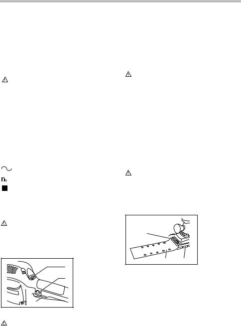
Install the pad for the hook-and-loop type of abrasive paper (optional accessory) on the tool. Tighten the screws firmly to secure the pad.
|
|
004436 |
|
|
|
|
|
|
1. |
Pad |
|
|
2 |
3 |
2. |
Screws |
|
1 |
3. |
Screwdriver |
|||
|
Installing paper dust bag
For BO4900, BO4900V only
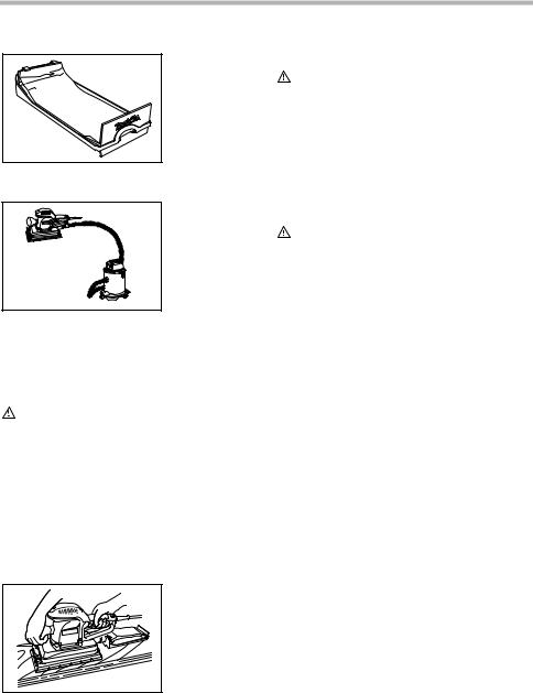
Place the paper dust bag on the paper dust bag holder with its front side upward. Insert the front fixing cardboard of the paper dust bag into the groove of the paper dust bag holder.
|
001685 |
|
|
1. |
Groove |
2 |
2. |
Front fixing |
1 |
|
cardboard |
|
3. |
Paper dust bag |
3
Then press the upper part of the front fixing card-board in arrow direction to hook it onto the claws.
|
001686 |
|
|
1 |
1. |
Claws |
|
2. |
Upper part |
||
|
2
Insert the notch of the paper dust bag into the guide of the paper dust bag holder. Then install the paper dust bag holder set on the tool.
001687
1. Guide
2. Notch
1
2
5
001688 |
Connecting to vacuum cleaner
004515
When you wish to perform cleaner operation, connect a vacuum cleaner to your tool. Connect a hose of vacuum cleaner to the dust nozzle.
OPERATION
CAUTION:
•Never run the tool without the abrasive paper. You may seriously damage the pad.
•Never force the tool. Excessive pressure may decrease the sanding efficiency, damage the abrasive paper or shorten tool life.
•The front grip is a screwed type one. Always be sure that the front grip is tightened securely before operation.
Turn the tool on and wait until it attains full speed. Then gently place the tool on the workpiece surface. Keep the base flush with the workpiece and apply a light pressure on the tool.
001689 |
MAINTENANCE
CAUTION:
•Always be sure that the tool is switched off and unplugged before attempting to perform inspection or maintenance.
To maintain product SAFETY and RELIABILITY, repairs, carbon brush inspection and replacement, any other maintenance or adjustment should be performed by Makita Authorized or Factory Service Centers, always using Makita replacement parts.
ACCESSORIES
CAUTION:
•These accessories or attachments are recommended for use with your Makita tool specified in this manual. The use of any other accessories or attachments might present a risk of injury to persons. Only use accessory or attachment for its stated purpose.
If you need any assistance for more details regarding these accessories, ask your local Makita Service Center.
•Abrasive papers (with pre-punched holes)
•Abrasive papers (without pre-punched holes)
•Abrasive papers (with pre-punched holes, hook- and-loop type)
•Punch plate
•Pad (for conventional type)
•Pad (for hook-and-loop type)
•Dust nozzle
•Dust bag
•Paper dust bag
•Paper dust bag holder
EN0006-1
MAKITA LIMITED ONE YEAR WARRANTY
Warranty Policy
Every Makita tool is thoroughly inspected and tested before leaving the factory. It is warranted to be free of defects from workmanship and materials for the period of ONE YEAR from the date of original purchase. Should any trouble develop during this one year period, return the COMPLETE tool, freight prepaid, to one of Makita’s Factory or Authorized Service Centers. If inspection shows the trouble is caused by defective workmanship or material, Makita will repair (or at our option, replace) without charge.
This Warranty does not apply where:
•repairs have been made or attempted by others:
•repairs are required because of normal wear and tear:
•the tool has been abused, misused or improperly maintained:
•alterations have been made to the tool.
6
 Loading...