


CGR3520ADT
Magic Chef CGR3520ADT, CGR3510ADH, CGR3520ADH, CGR3740ADH, CGR3740ADL Installation Instructions
...
INSTALLER: LEAVE THESE INSTRUCTIONS WITH THE APPLIANCE
' WIDE FREE-STANDING
AND SLIDE-IN
PLEASE.KEEP THIS MANUAL FOR FUTURE REFERENCE
THEMANUALIS INTENDEDTOASSISTIN THEINITIALINSTALLATIONAND ADJUSTMENTSOF THEF
!!!!i !ii!!i
i
CLEARANCE DIMENSIONS
Rangemaybeinstalledwithzeroinchesclearanceadjacentto (against)combustibleconstructionatther_
on the sidesbelowthe cooktop.For comp!eteinformationin regardto the installationof wallcabinets ab(
range and clearances to combustiblewall above the cooking top see the installation drawings. For SJ
CONSIDERATIONSdo notinstalla rangeinany combustiblecabinetrywhichisnot inaccordwith the inst_
drawings.
* NOTE:30 inchdimensionbetweencookingtop andwall cabinetshownonillustrationdoes notapplyto
withanelevatedoven.The30inchdimensionmaybe reducedto notlessthan24incheswhenthewall cabin
domestichomeare protectedwithfireproofmaterialsin accordancewithAmericanNationalStandards- N
FuelGasCodeor in mobilehomeswhentheyareprotectedwithfireproofmaterialsinaccordancewiththeF
Standardfor MobileHomeConstructionandSafety.
Toeliminatetheriskofburnsorfirebyreachingoverheatedsurfaceunits,cabinetstoragespacelocatedab(
surfaceunitsshouldbeavoided.If cabinetstorageisto be provided,the riskcanbereducedby installinga
hoodthat projects horizontallya minimumof 5 inches beyondthe bottomof thecabinets.
CAUTION:SOMECABINETSANDBUILDINGMATERIALSARENOTDESIGNEDTOWITHSTANDTHE
PRODUCED BY THE NORMAL SAFE OPERATION OF A LISTED APPLIANCE. DISCOLORATIOI
DAMAGE,SUCHAS DELAMINATION,MAYOCCUR.
YOUR RANGE MAY NOT BE EQUIPPED WITH SOME OF THE FEATURES REFERRED r
IN THtS MANUAL.
8101P1:
(08-

INSTALLATION DRAWINGS
GAS LINE
I" LOCATION NON-SELF
1/_" CLEANING MODELS.
FOR 120 VOLT
I" GROUNDED ELECTRICAL
OUTLET IN THIS AREA.
OUTLET MUST BE FLUSH.
AREA IS 13"W X 9"H,
-,_ LOCATED 9 3/8" ABOVE
FLOOR, AND 1 1/2" FROM
33" RIGHT WALL,
%
18" \
./ff _
21/,,', ..>"
< 25" NORMAL
CABINET
36" HEIGHT DEPTH
OF ABINET
/ 30" CABINET 24"
OPENI NG CABINET
RECOMMENDEDGAS LINE
LOCATION SELF-CLEAN
MODELS.
FREE-STANDING
NOTE:
23 3/4" ON CABINET TOPS WITH
FORMED FRONT EDGE,
MIN. FLAT SHAVE RAISED SECTION
AREA TO CLEAR TOP.
._ 23 1/2" 30"
UTOUT FOR 120 VOLT
GROUNDED ELECTRICAL
WITH THIS DIMENSION_ " OUTLET IN THIS AREA.
FILLER STRIP OR OUTLET MUST BE FLUSH.
OPTIONAL BACKGUARD AREA IS 13"W X 9"H,
IS NOT USED.
LOCATED 9 3/8" ABOVE
FOR CUTOUT GREATER FLOOR, AND 1 I/2" FROM
THAN 23 I/2" USE RIGHT WALL.
FILLER KIT, K6OFILL
OR CAX6OOOAXD.
OPT IONAL BACKGUARD
KIT K6OP OR
CAX6400AXO
MAY BE USED WHEN
CUTOUT IS 25".
36" HEIGHT
#'OF 25" MINIMUM
CABINET
BEFORE ATTEMPTING _(_ 3MMENDEOGAS CABINET
INSTALLATfON, ADJUST DEPTH
RANGE LEVELING LEGS I / _ LINE LOCATION
TO ACCOMMODATE | / 30" CABINET 2¢" CABINET
THIS DIMENSION. IL/_ _,,,..* OPENING
CAUTION:
SOMEWHITE EUROPEAN STYLE CABINETS ARE EQUIPPED WITH
DELICATE WHITE VINYL DRAWER AND DOOR FRONTS. THE VINYL
MAY NOT BE DESIGNED TO WITHSTAND THE HEAT PRODUCED BY THE
NORMALSAFE OPERATION OF A SELF-CLEANING RANGE.
DISCOLORATION OR DELAMI NATI ON MAY OCCUR.
TO AVOID POSSIBLE DAMAGE, WE RECOklMENDINCREASING THE 30" CABINET
OPENING TO 31 1/&" MINIMUM AND USING A HEAT SHIELD KIT--CABKIT V.
THE COUNTERTOP CUT. OUT MUST REMAIN 30".
SLIDE-IN
I
COVER
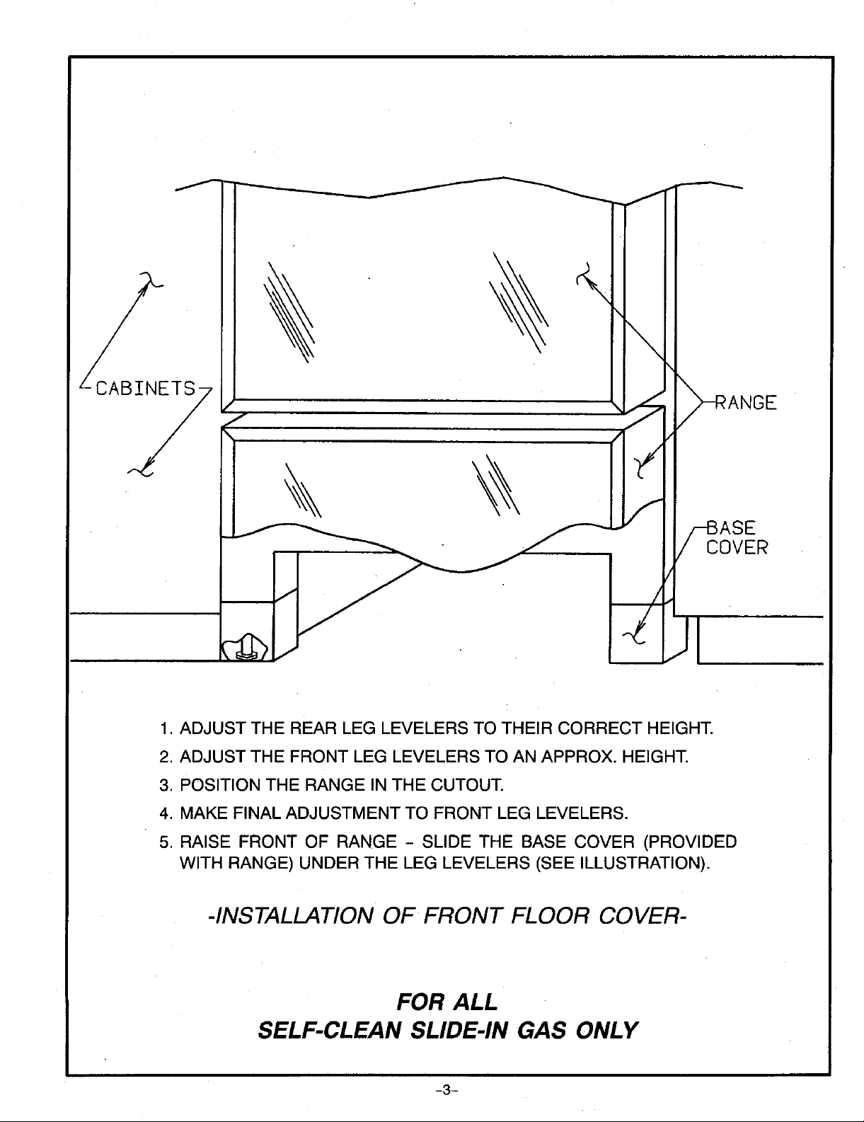
1. ADJUST THE REAR LEG LEVELERS TO THEIR CORRECT HEIGHT.
2. ADJUST THE FRONT LEG LEVELERS TO AN APPROX. HEIGHT.
3. POSITION THE RANGE IN THE CUTOUT.
4. MAKE FINAL ADJUSTMENT TO FRONT LEG LEVELERS.
5. RAISE FRONT OF RANGE - SLIDE THE BASE COVER (PROVIDED
WITH RANGE) UNDER THE LEG LEVELERS (SEE ILLUSTRATION).
-INSTALLATIONOF FRONT FLOOR COVER-
FOR ALL
SELF-CLEAN SLIDE-IN GAS ONLY
-3-

ANY COMBUSTIBLE
I _ --- _ SURFACE
/
/
/- F
I -3o- LI
MIN. OF CABINETS
I _ (SEE NOTE ON FRONT ABOVE COOK TOP
I 'o i,L I , J I'I o"CLEARANCE
MIN. I I I i J.
""] "_- _ _-'-_" "_-'------_" I _ _ COMBUSTIBLE
CONSTRUCTIONAND
II| T1
iO0 0 00'
li I > THE BACK AND SIDES
i
phil
OF THE RANGE
' ' ' ' BELOWTHE COOKING
SURFACE.
36"
IL I l
ART #9219-922
DIMENSION "A" SIDE CLEARANCE ABOVE COOKING SURFACE
TOP BURNER RATE FOR "'CONVENTIONAL SELF-CLEAN
NATURAL GAS (SEE RATING PLATE) OVEN OVEN
9,200 BTU/HR OR LESS 0 INCHES 3 INCHES
MORE THAN 9,200 BTU/HR 1 INCH 3 INCHES
Check the range model number plate to see if the range is RECREATIONALVEHICLES
approved for installation in mobile homes and/or The installation of a range designed for recreational vehicles
recreational vehicles. If approved the following items are must conform with state or other codes or, in the absence of
applicable, such codes, with the Standard for Recreational Vehicles,
ANSI A119.2-1atest edition.
MOBILE HOMES
In Canada the range must be installed in accordance with
The installation of a range designed for mobile home CAN/CSA- Z24062- Electrical Requirements for R V's
installation must conform with the Manufactured Home (CSA Standard CAN/CSA - Z240 RV Series) and Section
Construction and Safety Standard, Title 24 CFR, Part 3280 Z240.4.2 Installation Requirements for Propane
[formerly the Federal Standard for Mobile Home Appliances and Equipment in R.V.'s (CSA Standard
Construction and Safety, Title 24 HUD, (Part 280)] or, when CAN/CSA - Z240 RV Series).
such standard is not applicable, the Standard for
Manufactured Home installations, ANSi A225.1/NFPA LOCATINGTHE RANGE
501A, or with local codes. Do not set range over holes in the floor or other locations
In Canada the range must be installed in accordance with where it may be subject to strong drafts. Any opening in the
the current CSA Standard C22.1 - Canadian Electrical Code wall behind the range and in the floor under the range should
be sealed. Make sure the flow of combustion or ventilation
Part 1and Section 7240.4.1 - installation Requirements for air is not obstructed.
Gas Burning Appliances in Mobile Homes (CSA Standard
CAN/CSA- Z240MH). NOTE: A range should NOT be installed over kitchen
carpeting.
-4-
 Loading...