


Model BTWB530ST1

2
PRODUCT REGISTRATION
Thank you for purchasing a Magic Chef® product. The first step to protect your new product is to complete the product registration on our website: www.mcappliance.com/register. The benefits of registering your product include the following:
1.Registering your product will allow us to contact you regarding a safety notification or product update.
2.Registering your product will allow for more efficient warranty service processing when warranty service is required.
3.Registering your product could act as your proof of purchase in the event of insurance loss.
Once again, thank you for purchasing a Magic Chef® product.
ENG - 2

3
TABLE OF CONTENTS
PARTS |
4 |
SPECIFICATIONS |
4 |
IMPORTANT SAFETY INSTRUCTIONS |
5 |
INSTALLATION INSTRUCTIONS |
|
BEFORE USING YOUR APPLIANCE |
6 |
FREESTANDING INSTALLATION |
7 |
BUILT-IN INSTALLATION |
7 |
ELECTRICAL CONNECTION |
8 |
APPLIANCE FEATURES |
|
DUAL TEMPERATURE ZONES |
9 |
INTERIOR LIGHT |
9 |
ENGAGED WINE SHELVES |
9 |
TO REMOVE A SHELF |
9 |
TO REPLACE A SHELF |
9 |
UPPER ZONE |
10 |
LOWER ZONE |
10 |
OPERATING YOUR APPLIANCE |
|
TEMPERATURE CONTROL AND DISPLAY |
11 |
INDICATOR LIGHTS |
11 |
STANDBY |
11 |
LOCK AND UNLOCK |
12 |
TEMPERATURE SETTING |
12 |
INTERIOR LIGHT |
12 |
AUTOMATIC DEFROST |
13 |
CARE AND MAINTENANCE |
|
CLEANING YOUR APPLIANCE |
13 |
VACATION TIME |
13 |
MOVING YOUR APPLIANCE |
13 |
ENERGY SAVING TIPS |
13 |
TROUBLESHOOTING GUIDE |
14 |
WARRANTY |
16 |
ENG - 3
4
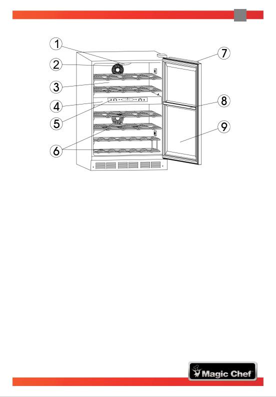
PARTS
1) |
Interior Light |
7) |
Door Handle |
2) |
Direct Current (DC) Electric Fan |
8) |
Partition Gasket |
3) Inner Rear |
9) |
Tempered Glass Door |
|
4)Zone Partition
5)Temperature Control & Display
6) Wire Shelf / Glass Shelf* |
*Shelves are available for either wine, |
|||||
|
|
|
|
beverage, or combination |
||
|
storage use |
|
|
|
|
|
SPECIFICATIONS |
|
|
|
|
|
|
|
|
|
|
|
|
|
|
Product Description |
|
Wine and Beverage Center |
|
||
|
|
|
|
|
|
|
|
Unit Dimensions |
Width |
|
Height |
|
Depth |
|
|
|
|
|
|
|
|
(inches) |
23.4” |
|
34.4” |
|
24.4” |
|
|
|
|
|||
|
|
|
|
|
|
|
|
Net Weight (lbs) |
|
|
108.4 lbs |
|
|
|
|
|
|
|
|
|
Note: Height includes door cap; Depth includes door handle.
ENG - 4

5
ENG - 5
6
IMPORTANT SAFETY INSTRUCTIONS
To reduce the risk of fire, electric shock and/or injury when using your appliance, follow these basic precautions:
Read all instructions before using the wine and beverage center.
DANGER or WARNING: Risk of child entrapment.
To avoid the possibility of child entrapment, please take the following precautions before throwing out the appliance:
-Remove all doors from the unit.
-Leave the shelves in place so that children may not easily climb inside.
Never allow children to operate, play with, or crawl inside the appliance.
Refrigerants: All refrigeration products contain refrigerants. Under the guidelines of federal law, refrigerants must be removed before the disposal of the product. It is the consumer’s responsibility to comply with federal and local regulations when disposing of this product.
Never clean the appliance parts with flammable fluids. The fumes can create a fire hazard or explosion.
Do not store or use gasoline or any other flammable vapors and liquids in the vicinity of this or any other appliance. The fumes can create a fire hazard or explosion.
SAVE THESE INSTRUCTIONS
INSTALLATION INSTRUCTIONS
Before Using Your Appliance
•Remove the exterior and interior packing.
•Before connecting the appliance to the power source, let it stand upright for approximately 4 hours. This will reduce the possibility of a malfunction in the cooling system resulting from improper handling during transportation.
•Clean the interior surface with lukewarm water using a soft cloth (see Care and Maintenance instructions on page 13).
ENG - 6
7
Freestanding Installation
•This appliance is designed to be built-in or freestanding.
•Locate the appliance away from direct sunlight and sources of heat (stove, heater, radiator, etc.). Direct sunlight may affect the acrylic coating and heat sources may increase electrical consumption. Ambient temperature below 68oF (20oC) or above 90oF (32oC) will hinder the performance of this appliance. This unit is not designed for use in a garage or any other outside installation.
•Avoid locating the appliance in moist areas.
•Plug the appliance into a dedicated, properly installed grounded wall outlet. This appliance should be operated on a separate electrical circuit from other operating appliances. Do not under any circumstances cut or remove the third (ground) prong from the power cord. Any questions concerning power and/or grounding should be directed toward a certified electrician or an authorized service center. This unit is not designed to be installed in an RV or used with an inverter.
•After plugging the appliance into a wall outlet, allow the unit to cool down for approximately 3-4 hours before placing wine bottles or beverage cans in the appliance.
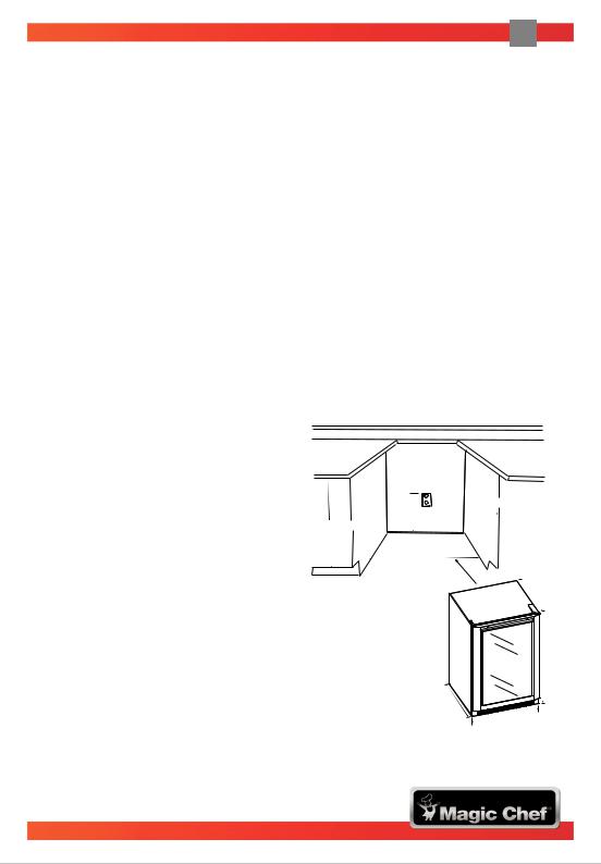
Built-In Installation
The cutout dimensions illustrated in |
|
|
Figure A allows the door to swing open |
|
|
and also allows access to the pull-out |
Locate Outlet |
|
|
||
shelves when installed as a built-in unit. |
24″Min. |
|
If you are installing the unit between |
||
6″Max. |
||
frameless cabinets, a ½” wide filler strip |
34-1/2″~35″ |
|
|
||
or side panel may be needed on the hinge |
24″Mix. |
|
side. The filler strip will act as a spacer |
|
|
between the appliance case and the |
|
|
adjacent cabinet door swing. The width of |
|
|
the opening must include the filler panels. |
|
|
Note: The door should protrude at least |
|
|
1” beyond the surrounding cabinets. |
24-2/5″ |
|
|
Including Handle |
23-2/5″
20-4/5″
34-2/5″
Figure A – The cutout depth must be 24”
ENG - 7
8
Electrical Connection
Improper use of the grounded plug can result in the risk of electric shock. If the power cord is damaged, please contact an authorized service center.
•This appliance should be properly grounded for your safety. The power cord of this appliance is equipped with a three-prong plug which mates with standard threeprong wall outlets to minimize the possibility of electric shock.
•Do not, under any circumstances, cut or remove the third ground prong from the power cord supplied.
•This appliance requires a standard 115V AC / 60Hz electrical outlet with a threeprong ground.
•This appliance is not designed to be used with an inverter.
•To prevent accidental injury, the power cord should be secured behind the appliance and not left exposed or hanging.
•Never unplug the appliance by pulling the power cord. Always grip the plug firmly and pull straight out from the receptacle.
•Do not use an extension cord with this appliance. If the power cord is too short, have a qualified electrician or service technician install an outlet near the appliance. The use of an extension cord can negatively affect the performance of the unit.
If any problems with the appliance persist, please contact the Customer Service Department at 888 775-0202 to consult with a representative. Or, visit our website at www.mcappliance.com to request warranty service.
ENG - 8
9
APPLIANCE FEATURES
Dual Temperature Zones
•There are two zones in this appliance. They are divided by a partition.
•Each zone has its independent temperature control and display.
•Each of the two zones can be used to store wine bottles or beverages.
•The upper zone can hold up to 16 bottles or 63 cans.
•The lower zone can hold up to 28 bottles or 77 cans.
Note: Besides the wine shelves made of steel wire, two glass shelves are supplied for your convenience to store beverages. Please keep the shelves that are temporarily not in use in good condition for future use.
Interior Light
•Each zone has its own interior light, which can be switched on or off by pressing the
light pad  on the control panel. Energy-efficient LEDs are installed for long-term durability.
Engaged Wine Shelves
•All of the shelves have tabs to engage the cabinet on both sides.
•Any of the shelves can be removed to accommodate larger bottles.
To Remove a Shelf
•Remove all bottles (cans) from the shelves.
•Lift the shelf upward and then gently pull out the shelf.
To Replace a Shelf
•Place the sides of the shelf back onto the supporting guides of the cabinet and push back until the shelf tabs slide into place.
Note: Ensure that the tabs are firmly engaged in place before storing any bottles.
ENG - 9
10
Upper Zone
•There are two wine shelves of full depth in the upper zone. Each shelf can hold up to 8 bottles with the necks of the bottles alternating front to back.
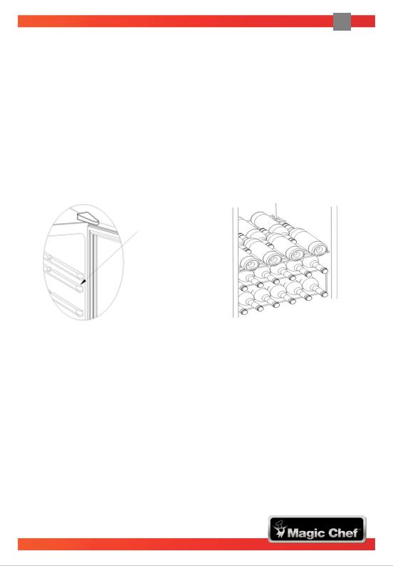
•The second supporting guide in the upper zone (counting from the top, see Figure B below) is not designed for wine storage; the shelves are for beverage use only.
Lower Zone
•There are two wine shelves of full depth in the lower zone. Each shelf can hold up to 8 bottles with the necks of the bottles alternating front to back.
•There are two wine racks in the lower zone. Each wire rack holds up to 6 bottles with the bottle necks facing the front (see Figure C below).
The Second
Supporting Guide
Figure B – For beverage use only |
Figure C – Each wire rack holds up to 6 bottles |
ENG - 10
11
OPERATING YOUR APPLIANCE
Temperature Control and Display
•The temperature in the upper zone and lower zone can be independently controlled and displayed.
•The temperature in either zone can be controlled between 39oF to 61oF (4oC to 16oC). (The zone temperature may have a tolerance of +/-5oF (+/-3oC) from the setting depending on different loading and ambient conditions).
•The temperature control and display, the  indicator, the warmer
  and
and  colder control pads near the symbol
  (left side) are for the upper zone of the wine cooler.
• The temperature control and display, the |
indicator, the warmer |
and |
colder |
|
control pads near the symbol |
(right side) are for the lower zone of the wine cooler. |
|||
•The indicator lights  for standby and
  lock, as well as the control pads to
  lock and for lighting
  are for both zones.
Indicator Light
•When lit, the  standby indicator light shows that the unit is in “Standby” mode.
•When lit, the  lock indicator light indicates that all of the control pads are locked and no adjustment can be made to that zone.
•When lit,  indicates that the corresponding zone is in the refrigeration cycle (compressor is running). The
  indicator light will turn off once the desired temperature is reached.
Standby
•When the unit is plugged in, the display and pads will illuminate for 3 seconds and an audible beep will be heard. Then the unit will automatically resume its previous setting from when it was switched off. If the unit was previously in “Standby” mode
when switched off, it will resume in “Standby” mode and the  standby indicator will remain lit.
•You can manually set your unit to “Standby” mode by pressing and holding both the
warmer  and
and  colder buttons of the lower zone control pads for approximately 3 seconds, provided that the control pads are unlocked and no other setting is in operation (the display does not flash). The
  standby indicator light will turn on to confirm “Standby” mode. Repeating this action once more will restart the unit.
ENG - 11
 Loading...