

MACKIE FRS1300 User Manual
FRS Series
OL
-3
-6
-9
-20
SIG
OL
-3
-6
-9
-20
SIG
2
OO
MAX
MAX
OO
1
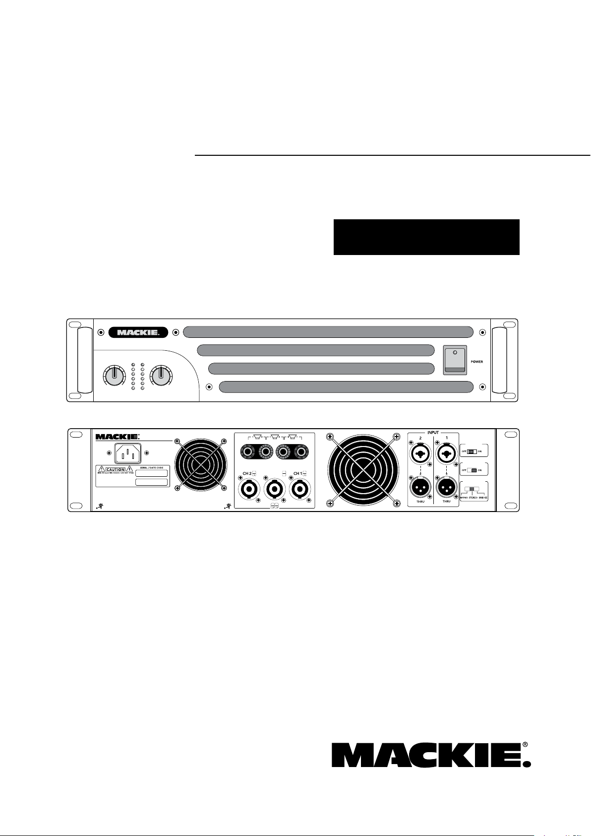
FRS•2800
FAST RECOVERY PO WER AMPLIFI ER
AMP MODE
DESIGNED BY MACKOIDS IN WOODINVILLE, WA, USA • MANUFACTURED IN CHINA FABRIQUE EN CHINE • COPYRIGHT ©2007
"MACKIE", AND THE RUNNING MAN FIGURE ARE TRADEMARKS OF LOUD TECHNOLOGIES, INC.
CHANNEL 2 CHANNEL 1
BRIDGED
BRIDGED
CH 1
CH 2
CLIP LIMIT
FILTER
SUBSONIC @ 30Hz
SPEAKER OUTPUTS
PIN
1+
1
PIN
1+
2+
1+
1
PIN
2+
2
PIN
1+
1
FAST RECOVERY
POWER AMPLIFIER
THIS DEVICE COMPLIES WITH PART 15 OF THE FCC RULES FOR
THE U.S. AND ICES-003, FOR CANADA. OPERATION IS SUBJECT
TO THE FOLLOWING TWO CONDITIONS: (1) THIS DEVICE MAY
NOT CAUSE HARMFUL INTERFERENCE, AND (2) THIS DEVICE
MUST ACCEPT ANY INTERFERENCE RECEIVED, INCLUDING
INTERFERENCE THAT MAY CAUSE UNDESIRED OPERATION.
WARNING
:
TO REDUCE THE RISK OF FIRE OR ELECTR IC
SHOCK, DO NOT EXPOSE THIS EQU IPMENT TO RAIN OR
MOISTURE. DO N OT REMO VE COVER . NO US ER SERVI CEABLE
PARTS INSIDE. REFER S ERVICING TO QUA LIFIED P ERSONNE L.
AVIS
:
RISQUE DE CHOC ELECTR IQUE — N E PAS O UVRIR
TWO CHANNEL POWER AMPLIFIERS
FRS•1300, FRS•1700, and FRS•2800
O W N E R ’ S M A N U A L

FRS SERIES AMPLIFIERS
FRS SERIES AMPLIFIERS
Important Safety Instructions
PORTABLE CART WARNING
Carts and stands - The
Component should be used
only with a cart or stand
that is recommended by
the manufacturer.
A Component and cart
combination should be
moved with care. Quick
stops, excessive force, and
uneven surfaces may cause
the Component and cart
combination to overturn.
CAUTION AVIS
RISK OF ELECTRIC SHOCK
DO NOT OPEN
RISQUE DE CHOC ELECTRIQUE
NE PAS OUVRIR
CAUTION: TO REDUCE THE RISK OF ELECTRIC SHOCK
DO NOT REMOVE COVER (OR BACK)
NO USER-SERVICEABLE PARTS INSIDE
REFER SERVICING TO QUALIFIED PERSONNEL
ATTENTION: POUR EVITER LES RISQUES DE CHOC
ELECTRIQUE, NE PAS ENLEVER LE COUVERCLE. AUCUN
ENTRETIEN DE PIECES INTERIEURES PAR L'USAGER. CONFIER
L'ENTRETIEN AU PERSONNEL QUALIFIE.
AVIS: POUR EVITER LES RISQUES D'INCENDIE OU
D'ELECTROCUTION, N'EXPOSEZ PAS CET ARTICLE
A LA PLUIE OU A L'HUMIDITE
The lightning flash with arrowhead symbol within an equilateral
triangle is intended to alert the user to the presence of uninsulated
"dangerous voltage" within the product's enclosure, that may be
of sufficient magnitude to constitute a risk of electric shock to persons.
Le symbole éclair avec point de flèche à l'intérieur d'un triangle
équilatéral est utilisé pour alerter l'utilisateur de la présence à
l'intérieur du coffret de "voltage dangereux" non isolé d'ampleur
suffisante pour constituer un risque d'éléctrocution.
The exclamation point within an equilateral triangle is intended to
alert the user of the presence of important operating and maintenance
(servicing) instructions in the literature accompanying the appliance.
Le point d'exclamation à l'intérieur d'un triangle équilatéral est
employé pour alerter les utilisateurs de la présence d'instructions
importantes pour le fonctionnement et l'entretien (service) dans le
livret d'instruction accompagnant l'appareil.
13.
1. Read these instructions.
2. Keep these instructions.
3. Heed all warnings.
4. Follow all instructions.
5. Do not use this apparatus near water.
6. Clean only with dry cloth.
7. Do not block any ventilation openings. Install in accordance with the
manufacturer’s instructions.
8. Do not install near any heat sources such as radiators, heat registers,
stoves, or other apparatus (including amplifiers) that produce heat.
9. Do not defeat the safety purpose of the polarized or grounding-type
plug. A polarized plug has two blades with one wider than the other.
A grounding-type plug has two blades and a third grounding prong.
The wide blade or the third prong are provided for your safety. If the
provided plug does not fit into your outlet, consult an electrician for
replacement of the obsolete outlet.
10.
Protect the power cord from being walked on or pinched particularly at
plugs, convenience receptacles, and the point where they exit from the
apparatus.
11.
Only use attachments/accessories specified by the manufacturer.
12.
Use only with a cart, stand, tripod, bracket, or table specified by the
manufacturer, or sold with the apparatus. When a cart is used, use
caution when moving the cart/apparatus combination to avoid injury
from tip-over.
Unplug this apparatus during lightning storms or when unused for long
periods of time.
14.
Refer all servicing to qualified service personnel. Servicing is required
when the apparatus has been damaged in any way, such as powersupply cord or plug is damaged, liquid has been spilled or objects have
fallen into the apparatus, the apparatus has been exposed to rain or
moisture, does not operate normally, or has been dropped.
15.
This apparatus shall not be exposed to dripping or splashing, and no
object filled with liquids, such as vases or beer glasses, shall be placed
on the apparatus.
16.
This apparatus has been designed with Class-I construction and must
be connected to a mains socket outlet with a protective earthing con
nection (the third grounding prong).
17.
This apparatus has been equipped with an all-pole, rocker-style AC
mains power switch. This switch is located on the front panel and
should remain readily accessible to the user.
18. This apparatus does not exceed the Class A/Class B (whichever is
applicable)
set out in the radio interference regulations of the Canadian Department
of Communications.
ATTENTION — Le présent appareil numérique n’émet pas de bruits
radioélectriques dépassant las limites applicables aux appareils numériques de
class A/de class B (selon le cas) prescrites dans le réglement sur le brouillage
radioélectrique édicté par les ministere des communications du Canada.
19.
Exposure to extremely high noise levels may cause permanent hearing
loss. Individuals vary considerably in susceptibility to noise-induced
hearing loss, but nearly everyone will lose some hearing if exposed to
sufficiently intense noise for a period of time. The U.S. Government’s
Occupational Safety and Health Administration (OSHA) has specified
the permissible noise level exposures shown in the following chart.
-
limits for radio noise emissions from digital apparatus as
According to OSHA, any exposure in excess of these permissible limits
could result in some hearing loss. To ensure against potentially danger
ous exposure to high sound pressure levels, it is recommended that all
persons exposed to equipment capable of producing high sound pres
sure levels use hearing protectors while the equipment is in operation.
Ear plugs or protectors in the ear canals or over the ears must be worn
when operating the equipment in order to prevent permanent hearing
loss if exposure is in excess of the limits set forth here.
Duration Per Day Sound Level dBA, Typical
In Hours Slow Response Example
8 90 Duoinsmallclub
6 92
4 95 SubwayTrain
3 97
2 100 Veryloudclassicalmusic
1.5 102
1 105 DavescreamingatSteveaboutdeadlines
0.5 110
0.25orless 115 Loudestpartsatarockconcert
WARNING — To reduce the risk of fire or
electric shock, do not expose this apparatus
to rain or moisture.
-
-

Contents
Owner’s Manual
IMPORTANT SAFETY INSTRUCTIONS ........................ 2
INTRODUCTION ...................................................... 4
GETTING STARTED ................................................... 5
HOOKUP DIAGRAMS............................................... 6
FRONT PANEL FEATURES ......................................... 8
1. POWER ....................................................... 8
2. VENTILATION .............................................. 8
3. METERS ...................................................... 8
4. LEVEL CONTROLS......................................... 8
REAR PANEL FEATURES ........................................... 9
5. POWER CORD SOCKET ................................ 9
6. FAN VENTS.................................................. 9
7. SPEAKER OUTPUTS ...................................... 9
8. COMBO INPUTS .......................................... 9
9. THRU OUTPUTS .......................................... 9
10. AMP MODE ............................................ 10
11. CLIP LIMIT .............................................. 10
12. SUBSONIC FILTER ................................... 10
GENERAL PRECAUTIONS ........................................ 11
AC POWER REQUIREMENTS ........................... 11
THERMAL CONSIDERATIONS .......................... 11
RACK MOUNTING .......................................... 11
MAINTENANCE .............................................. 11
APPENDIX A: SERVICE INFORMATION .................... 12
TROUBLESHOOTING ...................................... 12
REPAIR ......................................................... 13
APPENDIX B: CONNECTIONS, MATH AND STUFF ..... 14
XLR CONNECTORS ......................................... 14
1/4" TRS PHONE PLUGS AND JACKS ............. 14
1/4" TS PHONE PLUGS AND JACKS ................ 14
SPEAKONS .................................................... 14
LOUDSPEAKER CABLE .................................... 14
LONGER LENGTHS ......................................... 15
SPEAKER IMPEDANCES .................................. 15
APPENDIX C: TECHNICAL INFO............................... 16
SPECIFICATIONS ............................................ 16
BLOCK DIAGRAM .......................................... 17
DIMENSIONS ................................................. 18
LIMITED WARRANTY ............................................. 19
Need help with your new FRS amplier?
• Visit www.mackie.com and click Support to nd:
FAQs, manuals, addendums, and user forums.
• Email us at: techmail@mackie.com.
• Telephone 1-800-898-11 to speak with one of our splendid
technical support representatives, (Monday through Friday,
from 7 a.m. to 5 p.m. PST).
Part No. SW0588 Rev. D 01/08
©2007-2008 LOUD Technologies Inc. All Rights Reserved.
Born and raised on an amp farm by the banks of Woodinville Slough, WA.
Owner’s Manual

FRS SERIES AMPLIFIERS
FRS SERIES AMPLIFIERS
Introduction
Congratulations on the purchase of your new Mackie
power amplifier. Please read these instructions to get
the maximum performance from your amplifier, and to
make the technical writer feel loved.
The FRS series amplifiers are designed for continuous duty in speech, music, and sound reinforcement
applications in churches, schools, offices, arenas, hotel
meeting rooms, convention centers, recreation facilities
and other venues demanding high performance, flexible
features, and rugged dependability.
The switching power supply allows for high efficiency
and performance without the heavy weight of amplifiers
with conventional AC transformers.
A rear panel low-cut switch allows you to remove low
frequencies, and a clip-eliminator allows extra protection for your speakers by preventing the amplifier from
being overloaded.
The amplifier can operate in stereo, dual-mono, or
bridged-mono. The output connections are Speakons®
and binding posts for left, right, and bridged mono.
The combination inputs are capable of accepting
balanced XLR, 1/4" TRS, or unbalanced 1/4" TS connections from line-level sources. Two XLR through-outputs
allow the balanced input signals to be shared with other
amplifiers, or powered speakers etc.. Two front panel
level controls allow adjustment of the input signals.
The front panel has a rocker power switch with a
power LED, and each channel has a high-resolution
six-segment LED meter.
The amplifier output stage is fully protected against
permanent damage caused by overloading, shorts, silky
boxers, and extreme temperatures.
The front panel incorporates holes for rack mounting,
where it will take up two rather lovely rack spaces. Two
handles are fitted on the front panel for easy transporting.
Please write your serial number here for future
reference (i.e., insurance claims, tech support,
return authorization, etc.)
Purchased at:
Date of purchase:
FEATURES
• Professional lightweight power amplifier with
high-power / low-distortion design
• Fast Recovery circuitry for clean, undistorted
sound — even at clipping
• Ultra-light switching power supply for maxi
mum efficiency and minimal heat
• Available in three powerful models, with
continuous power @ 4 ohms bridged of:
FRS•1300: 1300 W
FRS•1700: 1660 W
FRS•2800: 2800 W
• Selectable dual-mono, stereo, or bridged-mono
operating modes
• 6-segment LED meter per channel, with OL
(overload) and SIG (signal present) LEDs
• Defeatable clip limiter plus short, under-imped
ance, over-current, and thermal protection
• 30 Hz subsonic filter maximizes amplifier ef
ficiency and headroom
•
Combo XLR/TRS input and TRS thru connectors
per channel
• Detented rotary gain controls
•
Speakon® and binding post outputs per channel
• Third Speakon output for bridged mono appli
cations, also provides both output channels on
a single connector (mono/stereo modes)
• Multi-speed fans adjust to operating tempera
ture for minimal acoustic noise
• Robust, impact-resistant, all-steel 2U rack
mount chassis
• Comfortable handles for easy transport and
protection of level controls
-
-
-
-
-
HOW TO USE THIS MANUAL
After this introduction, a getting started guide will
help you get things set up fast. The hook-up diagrams
show some typical setups. The features section describes
every detail and control, and you’ll find illustrations
with each feature numbered and described.
This icon marks information that is critically
important or unique to the amplifier. For your
own good, read and remember them.
This icon leads you to in-depth explanations
of features and practical tips. They usually
have some valuable nuggets of information.
Appendix A is a section on troubleshooting and repair.
Appendix B is a section on connectors.
Appendix C shows the technical specifications.
-

Getting Started
Owner’s Manual
The following steps will help you set up your
amplifier, and get the levels just right.
Settings:
1. Be sure the amplifier’s power switch is off.
2. Turn down both level controls.
3. On the rear panel, set the subsonic filter switch
off and the clip limit switch on.
4. Determine which amp mode is best for your
application:
Stereo mode is the typical setup for amplify-
ing stereo signals. Input 1 is routed to channel
1 output, and input 2 is routed to channel 2
output.
Mono mode is used for sending a mono signal
to both outputs, with separately adjustable
level controls. Input 1 is used in mono mode
(leave input 2 disconnected).
Bridge mode uses both amplifier channels to
power one speaker (or set of speakers). Input
1 is used in bridge mode (leave input 2 disconnected and its level control turned down).
5. Set the amp mode switch according to your ap
plication and delicate sensibilities.
Note: 4 ohms is the minimum speaker
impedance you should connect to the
amplifier in bridge mode.
Connections:
1. Using balanced cables, make connections from
your mixer (or other signal source) main out to
your amplifier’s inputs.
2. In stereo mode, connect the cables from your
signal source to the amplifier’s combo input
jacks, either XLR or 1/4" TRS. The XLR and TRS
inputs for each channel are wired in parallel.
• The balanced XLR inputs are wired as follows:
Pin 1 = shield (ground)
Pin 2 = hot (+)
Pin 3 = cold (–)
• The 1/4" TRS inputs are wired as follows:
Tip = hot (+)
Ring = cold (–)
Sleeve = shield (ground)
3. In mono mode and bridge mode, connect one
cable from the input source to input 1, and connect nothing to input 2.
4. In stereo and mono modes, connect speaker
cables to the speaker outputs, either the binding posts or the Speakon connectors.
• The binding post connectors are wired as follows:
Red = hot (+ speaker terminal)
Black = cold (– speaker terminal)
• The speakon connectors are wired as follows:
1+ = hot (+ speaker terminal)
1– = cold (– speaker terminal).
5. In bridge mode, if using the binding post out
puts:
Ch 1 red post = hot (+ speaker terminal)
Ch 2 red post = cold (– speaker terminal)
Do not use the black terminals.
If using a speakon, connect it to the center
bridged speakon connector. This is wired as follows:
1+ = hot (+ speaker terminal)
2+ = cold (– speaker terminal)
6. Plug all the sound system components into suit
able AC outlets, properly grounded and capable
of delivering adequate current.
7. Make sure your signal source is powered up and
delivering signal to the amplifier.
8. Turn the power amplifier’s switch on. Verify that
-
the power LED lights.
9.
Slowly turn up both level controls on the amplifier. You should hear music and see the meters
and sig LEDs flashing. If the OL (overload)
LEDs are flashing, turn down either the level
controls on the amp or the source signal’s output level controls (i.e., master faders), until the
OL LEDs either blink occasionally or not at all.
10. For quieter listening, it is preferable to adjust
the amp’s level controls rather than the source
signal’s output level (unless you have the
source’s control all the way up!).
-
-
Things to remember:
• Never plug amplifier outputs into anything
except speakers (unless you have an outboard
box specifically designed to handle speakerlevel signals). Pumpkins are right out.
• Before making connections to an amp or recon
figuring an amp’s routing, turn the amp’s level
controls down, turn the power off, make the
changes, turn the power back on, and then turn
the level controls back up.
• If you shut down your equipment, turn off the
amplifiers first. When powering up, turn on the
amplifiers last.
-
Owner’s Manual
5
FRS SERIES AMPLIFIERS
FRS SERIES AMPLIFIERS
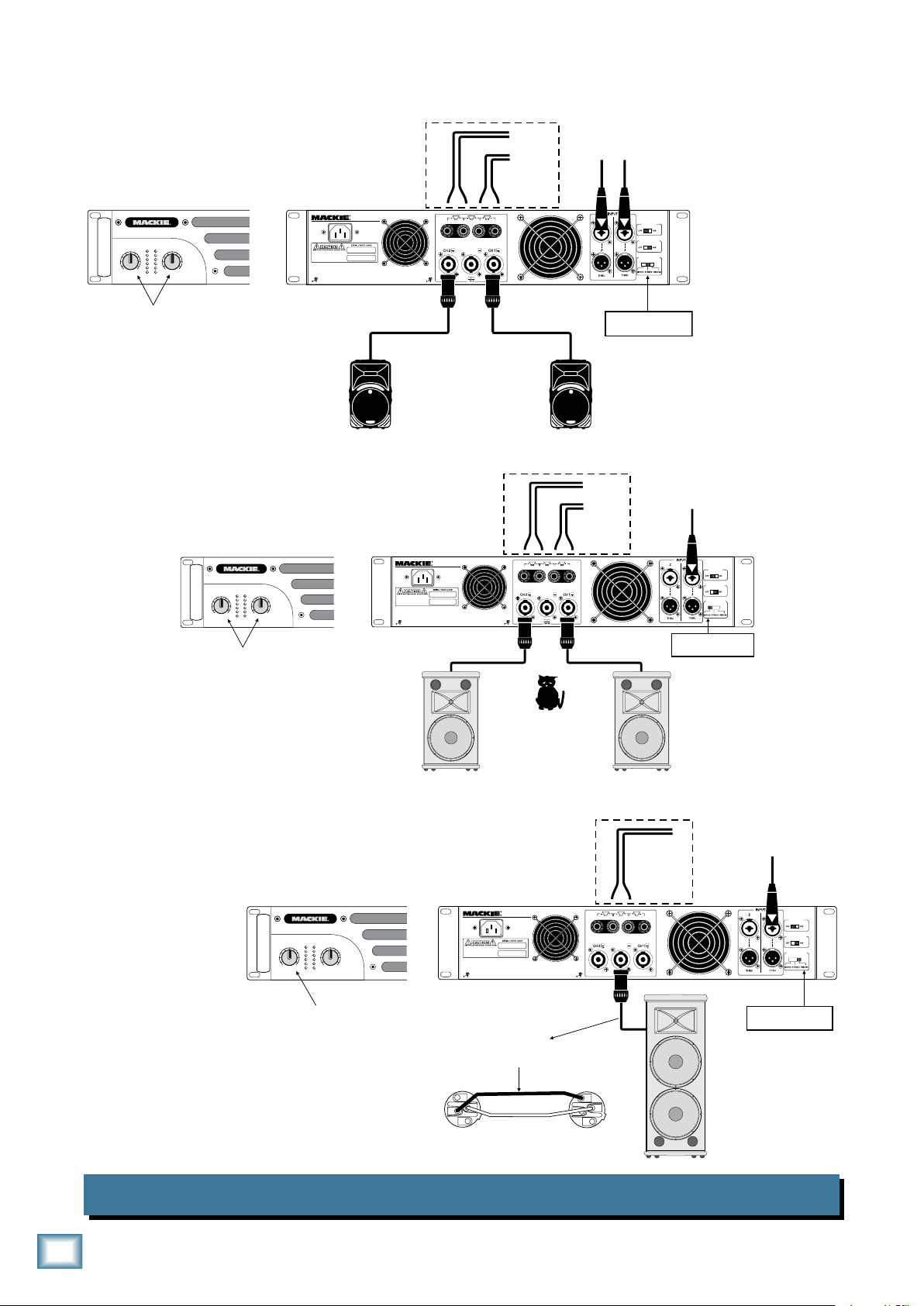
Hookup Diagrams
AMP MODE
DESIGNED BY MACKOIDS IN WOODINVILLE, WA, USA • MANUFACTURED IN CHINA FABRIQUE EN CHINE • COPYRIGHT ©2007
"MACKIE", AND THE RUNNING MAN FIGURE ARE TRADEMARKS OF LOUD TECHNOLOGIES, INC.
CHANNEL 2 CHANNEL 1
BRIDGED
BRIDGED
CH 1 CH 2
CLIP LIMIT
FILTER
SUBSONIC @ 30Hz
SPEAKER OUTPUTS
PIN
1+
1
PIN
1+
2+
1+
1
PIN
2+
2
PIN
1+
1
FAST RECOVERY
POWER AMPLIFIER
THIS DEVICE COMPLIES WITH PART 15 OF THE FCC RULES FOR
THE U.S. AND ICES-003, FOR CANADA. OPERATION IS SUBJECT
TO THE FOLLOWING TWO CONDITIONS: (1) THIS DEVICE MAY
NOT CAUSE HARMFUL INTERFERENCE, AND (2) THIS DEVICE
MUST ACCEPT ANY INTERFERENCE RECEIVED, INCLUDING
INTERFERENCE THAT MAY CAUSE UNDESIRED OPERATION.
WARNING
:
TO REDUCE THE RISK OF FI RE OR EL ECTRIC
SHOCK, DO NOT EXPOSE THI S EQUIPM ENT TO RAIN OR
MOISTURE. DO NOT REMOVE COVER. N O USER SERVICE ABLE
PARTS INSIDE. REFER SERV ICING TO QUALIF IED PER SONNEL.
AVIS
:
RISQUE DE CHOC ELECTRIQU E — NE P AS OUVR IR
FROM MIXING CONSOLE
LEFT AND RIGHT MAIN OUT
AMP MODE SWITCH
STEREO
Passive Speakers
(Mackie C300z)
TO
SPEAKERS
+
+
OPTIONAL CONNECTION USING BINDING POSTS
In STEREO mode,
both gain controls
are used to achieve
a nice balance
OL
-3
-6
-9
-20
SIG
OL
-3
-6
-9
-20
SIG
2
OO
MAXMAX
OO
1
FRS•2800
FAST RECOVERY POWER AMPLIF IER
AMP MODE
DESIGNED BY MACKOIDS IN WOODINVILLE, WA, USA • MANUFACTURED IN CHINA FABRIQUE EN CHINE • COPYRIGHT ©2007
"MACKIE", AND THE RUNNING MAN FIGURE ARE TRADEMARKS OF LOUD TECHNOLOGIES, INC.
CHANNEL 2 CHANNEL 1
BRIDGED
BRIDGED
CH 1 CH 2
CLIP LIMIT
FILTER
SUBSONIC @ 30Hz
SPEAKER OUTPUTS
PIN
1+
1
PIN
1+
2+
1+
1
PIN
2+
2
PIN
1+
1
FAST RECOVERY
POWER AMPLIFIER
THIS DEVICE COMPLIES WITH PART 15 OF THE FCC RULES FOR
THE U.S. AND ICES-003, FOR CANADA. OPERATION IS SUBJECT
TO THE FOLLOWING TWO CONDITIONS: (1) THIS DEVICE MAY
NOT CAUSE HARMFUL INTERFERENCE, AND (2) THIS DEVICE
MUST ACCEPT ANY INTERFERENCE RECEIVED, INCLUDING
INTERFERENCE THAT MAY CAUSE UNDESIRED OPERATION.
WARNING
:
TO REDUCE THE RISK OF FIR E OR ELE CTRIC
SHOCK, DO NOT EXPOSE THIS EQUIPME NT TO R AIN OR
MOISTURE. DO NOT REMOVE C OVER. NO USER S ERVICEAB LE
PARTS INSIDE. REFER SERVI CING TO QUALIFI ED PERSO NNEL.
AVIS
:
RISQUE DE CHOC ELECTRIQUE — NE PA S OUVRI R
FROM
MIXING CONSOLE
MONO OUT
AMP MODE SWITCH
MONO
CH 1 AND CH 2
PLAY THE SAME
TO
SPEAKERS
+
+
OPTIONAL CONNECTION USING BINDING POSTS
Passive loudspeakers
Mackie S215
Confused cat
???
Passive loudspeakers
Mackie S215
In MONO mode,
both gain controls
are used to acheive
a nice balance
OL
-3
-6
-9
-20
SIG
OL
-3
-6
-9
-20
SIG
2
OO
MAXMAX
OO
1
FRS•2800
FAST RECOVERY POWER AMPLIFI ER
AMP MODE
DESIGNED BY MACKOIDS IN WOODINVILLE, WA, USA • MANUFACTURED IN CHINA FABRIQUE EN CHINE • COPYRIGHT ©2007
"MACKIE", AND THE RUNNING MAN FIGURE ARE TRADEMARKS OF LOUD TECHNOLOGIES, INC.
CHANNEL 2 CHANNEL 1
BRIDGED
BRIDGED
CH 1 CH 2
CLIP LIMIT
FILTER
SUBSONIC @ 30Hz
SPEAKER OUTPUTS
PIN
1+
1
PIN
1+
2+
1+
1
PIN
2+
2
PIN
1+
1
FAST RECOVERY
POWER AMPLIFIER
THIS DEVICE COMPLIES WITH PART 15 OF THE FCC RULES FOR
THE U.S. AND ICES-003, FOR CANADA. OPERATION IS SUBJECT
TO THE FOLLOWING TWO CONDITIONS: (1) THIS DEVICE MAY
NOT CAUSE HARMFUL INTERFERENCE, AND (2) THIS DEVICE
MUST ACCEPT ANY INTERFERENCE RECEIVED, INCLUDING
INTERFERENCE THAT MAY CAUSE UNDESIRED OPERATION.
WARNING
:
TO REDUCE THE RISK OF FI RE OR EL ECTRIC
SHOCK, DO NOT EXPOSE THI S EQUIPM ENT TO RAIN OR
MOISTURE. DO NOT REMOVE COVER. N O USER SERVICEA BLE
PARTS INSIDE. REFER SERV ICING TO QUALIF IED PERS ONNEL.
AVIS
:
RISQUE DE CHOC ELECTRIQU E — NE P AS OUVR IR
FROM
MIXING CONSOLE
MONO OUT
AMP MODE SWITCH
BRIDGE
POWER OF CH 1 AND CH 2
IS COMBINED
Passive Speaker
(Mackie S225)
If you have two amplifiers, each could power a
single speaker in bridged mono, to make a very
powerful stereo system. Use a stereo feed from
your mixing console, the left goes to one amp,
and the right goes to the other.
TO
SPEAKER
+
+
OPTIONAL CONNECTION USING BINDING POSTS
Crossover Cable
Pin 1+ to Pin 1+
Pin 2+ to Pin 1–
In BRIDGED mode,
only use this gain control
COLD
HOT
SPEAKER END
AMPLIFIER END
1+
1–
2–
2+
1+
1–
2–
2+
OL
-3
-6
-9
-20
SIG
OL
-3
-6
-9
-20
SIG
2
OO
MAXMAX
OO
1
FRS•2800
FAST RECOVERY POWER AMPLIF IER
Stereo
Dual mono
Bridged mono
STEREO, DUAL MONO, AND BRIDGED MONO
 Loading...