

Page 1

M•1400 / M•1400i / M•1200
SERVICE MANUAL
Version 1.2
1998 MACKIE DESIGNS, INC.
820-179-00
Page 2

CAUTION AVIS
CAUTION
AVIS
RISK OF ELECTRIC SHOCK
DO NOT OPEN
RISQUE DE CHOC ELEC TRIQUE
NE PAS OUVRIR
CAUTION: TO REDUCE THE RISK OF
ELECTRIC SHOCK DO NOT REMO VE
THE COVER
NO USER SE RVIC EABLE PARTS INSIDE
REFER SERVICING TO QUALIFIED
PERSONN EL
WARNING: TO REDUCE THE RISK OF
FIRE OR ELECTRIC SHOCK, DO N OT
EXPOSE THIS PRODUCT TO RAIN OR
MOISTURE
TO PREVENT ELECTRIC SHOCK, DO
NOT USE THIS POLARIZED PLUG WITH
AN EXTENSION CORD, RECEPTAC LE OR
OTHER OUTLET UNLESS THE BLADES
CAN BE FULLY INSER TED TO PREVENT
BLADE EXPOSURE.
The lig htning flash w ith arro wh ea d symb o l within an
e quilate ral trian gle is inte nde d to ale rt the use r to the
p rese nc e o f uninsulate d "d ang ero us vo lta ge " w ithin the
p rod uc t's e nc lo sure , tha t ma y b e o f suffic ient m ag nitud e to
c on stitud e a risk o f ele ctric sho c k to pe rson s.
Le symb o le é c la ir a ve c po int d e flé c he à l'inte rie ur d'un
tria ng le é q uila té ra l e st utilisé p our a le rte r l'utilisa te ur d e la
p ré se nce à l'inte rieur d u c of fre t d e "vlo tag e d ang e re ux" no n
iso le d 'a mp le ur suffisa nte p o ur c on stitue r un risq ue
d 'é lé c tro c ution.
AT TENT ION : POUR EVITE R LE S
RI SQUES DE CHOC ELECT R IQU E, NE
PA S EN LEV ER L E COUV ERCLE . A U CUN
EN TRET IEN DE PIECE S IN TER IEUR ES
PAR L'US AGE R. C ONFIER L 'ENT RET IEN
AU PER SON NEL QUALIF IE .
AV IS:POUR EV ITER LE S R ISQUES
D'I NCE NDI E OU D'ELECT R OCU TION,
N'EXP OSEZ PAS CET ARTIC LE A LA
PLUIE O U A L'H UMIDITE.
POUR PREVE NIR LES CHOC S
ELECT RIQUES NE PAS UTIL ISE R CE TTE
FICHE PO LA RI SEE AVEC UN
PR OLON GAT EUR, UN PRISE D E
COURA N T O U UNE AUTRE S ORT IE DE
COURA NT, SAUF SI LES LA MES
PE UVEN T E TRE INSEREE S A FOND
SA N S L AIS SER AUC UNE PA R T IE A
DE C OUVER T .
The exc lam ation p o int within a n e q uila te ra l tria ng le
is intend e d to a le rt the use r to the p re se nc e of
imp o rta nt op e ra ting and ma inte nan c e ( se rvicing )
instruc tio ns in the literature a c c om pa nying the
a pp lia nce .
Le p o int d'e xc la ma tio n à l'inté rie ur d 'u n tria ng le d e
la pré se nc e d 'instruc tio ns imp orta nte s p ou r le
fo nc tio nne me nt e t l'e ntre tien (se rvic e ) da ns le livre t
d 'in struc ion a c c o mp a g na nt L'a p p a re il.
Page 3

®
Click on any item to open that page
TABLE O F C ONTENTS
INTRO DUC TION............................................................. 2
SYSTEM O VERVIEW ....................................................... 3
SUMMARY O F FEATURES .....................................................................4
SPEC IFIC ATIO NS...................................................................................6
C IRC UIT THEO RY........................................................... 8
INPUT C IRCUITRY..................................................................................8
POWER AMPLIFIER C IRC UITRY...........................................................8
PRO TEC TION C IRCUITS .......................................................................9
THERMAL MANAG EMENT..................................................................10
SERVIC E PRO C EDURES............................................... 11
REQ UIRED EQ UIPMENT LIST..............................................................11
TRO UBLESHO O TING TIPS - O UTPUT FAILURES................................12
TEST AND BIASING PRO C EDURE......................................................13
PARTS............................................................................ 15
Q UIC K PARTS......................................................................................15
C HASSIS ASSEMBLY............................................................................16
HEATSINK ASSEMBLY..........................................................................18
C O MPLETE PARTS LIST........................................................................20
SC HEMATIC S / PC B LAYO UTS.................................... 23
INPUT PCB SC HEMATIC .....................................................................23
INPUT PCB LAYOUT............................................................................24
DISPLAY PCB SCHEMATIC ................................................................25
DISPLAY PCB LAYO UT........................................................................26
MAIN PC B SC HEMATICS...................................................................27
MAIN PC B LAYO UT............................................................................30
SOFT START PC B SC HEMATIC ...........................................................31
SOFT START PC B LAYO UT...................................................................32
Page 4

INTRO DUC TION
This ma nua l c o nta ins c o m p le te se rvic e info rma tio n fo r the M•1200, M•1400 a nd M•1400i
a ud io p o we r a m p lifie rs. O p e ra ting instruc tio ns will be to uc he d o n b rie fly. Fo r c o mp le te
o p e ra ting instruc tio ns re fe r to the o w ne r’ s ma nua l.
The FR Se rie s M•1200 a nd M•1400 a re hig h p o we r a ud io a mp lifie rs de sig ne d fo r
p ro fe ssio na l ap p lic atio ns. The y fe ature a ud io p hile q ua lity so und , e xc e lle nt stab ility,
e xte nsive pro tec tio n c irc uitry, a nd le g e nd a ry Ma c kie re lia b ility. Pa te nte d Fa st Re c o ve ry
c irc uitry a llo ws the M•1200/ M•1400 to re c o ve r fro m c lip p ing w itho ut g e ne ra ting
und e sira b le a rtifa c ts.
SERVIC E O N THE M•12 00/ M•1400 IS
TO BE PERFO RMED BY EX PERIENCED
M•1200/M•1400 SERVIC E MANUAL
TECHNICIANS O NLY!
To se rvic e the M•1200/ M•1400, te c hnic ia ns sho uld b e fa milia r with o p -a m p s, d isc re te
a na lo g c irc uitry, a nd tro ub le sho o ting high p o w e r so lid state a m p lifie rs. Pre se ntatio n o f
this ma nua l do e s no t c o nstitute e ndo rse me nt o f q ua lific a tio ns b y Ma c kie De sig ns.
TECHNIC AL SUPPO RT
Ma c kie De sig ns Te c hnic a l Sup p o rt De p a rtme nt is a va ila ble 8AM - 5PM PST, Mo nd a y Frid a y a t 1-800-258-6883 (o utsid e US c a ll 011-425-487-4333) Ple a se fe e l fre e to c a ll w ith
a ny q ue stio ns (Be tte r sa fe tha n so rry!).
DISCLAIMER
! SMD !
The M•1200/ M•1400 m a ke s e xte nsive
use o f surfa c e m o unt c o mp o ne nts.
Se rvic ing te c hnic ia ns sho uld ha ve the
to o ls a nd e xp e rie nc e to p e rfo rm
surfa c e mo unt re w o rk.
The info rm a tio n c o nta ine d in this ma nua l is p ro p rie ta ry to Ma c kie De sig ns, Inc . The
e ntire m a nua l is p ro te c te d unde r c o p yrig ht a nd m a y no t b e re p ro d uc e d b y a ny me a ns
witho ut e xp ress writte n p e rmissio n fro m Ma c kie De sig ns, Inc .
2
INTRO DUCTIO N
Page 5

VERSIO N 1.1
SYSTEM O VERVIEW
This se c tio n p ro vide s a q uic k summa ry o f the M•1200/ M•1400’ s ma jo r fe ature s. It is no t
inte nd e d to ta ke the p la c e o f the o w ne r’ s ma nua l. It is inc lud e d he re to he lp se rvic ing
te c hnic ia ns familia rize the mse lve s with the M•1200/ M•1400.
DIFFERENC ES BETWEEN THE M•1400, M•1400i AND M•1200
The M•1200 a nd M•1400 a re e le c tro nic a lly ide ntic a l pro d uc ts w ith the fo llo wing
e xc e ptio ns:
1. The M•1400 ha s 12,000uF ma in filte r c ap s, whe re the M•1200 a nd M•1400i ha ve
10,000uF.
2. The M•1400 a nd M•1400i use a m o re p o we rful fa n tha n the M•1200.
3. The M•1400 ha s Sp e a ko n
spe a ke r o utputs (b o th in a d d itio n to bind ing p o sts).
The M•1200 wa s d isc o ntinue d in 1998 a nd re p lac e d b y the M•1400i.
Exp o rt M•1400’ s a lso ha ve a “ So ft Start” c irc uit tha t is no t insta lle d o n Am e ric a n units.
c o nne c to rs whe re the M•1200 a nd M•1400i ha ve ¼”
FAST REC O VERY DESIG N
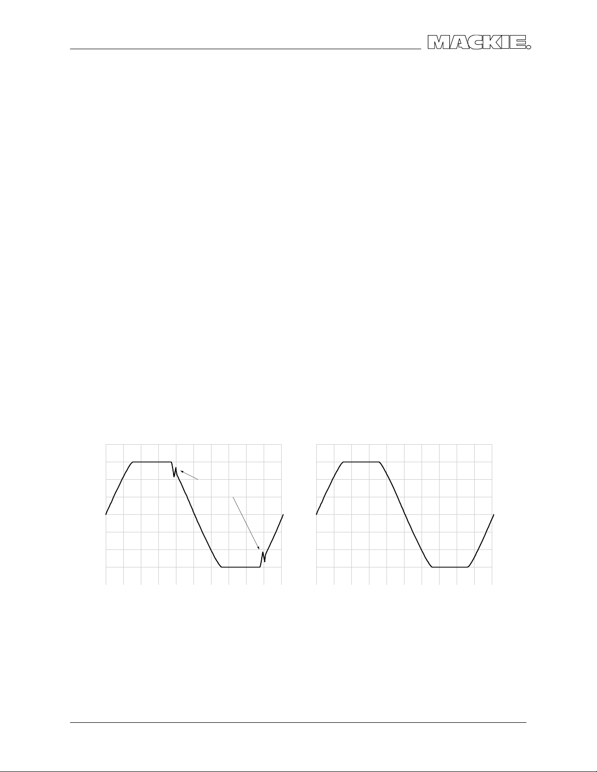
So lid sta te po w e r a m p lifie rs ha ve a re p utatio n fo r so und ing ha rsh whe n d rive n into
c lipp ing . The usua l e xp la na tio n is o d d ha rmo nic s g e ne ra te d b y ha rd c lip p ing , b ut In
fa c t muc h o f the unp le a sant so und is c a use d b y la tc hing a nd p a ra sitic o sc illa tio ns tha t
o c c ur a s the a m p lifie r re c o ve rs fro m c lip p ing .
TYPICAL AMPLIFIER MACKIE FR SERIES
Ma c kie ’ s Fa st Re c o ve ry d e sig n re c o ve rs fro m c lip p ing quic kly w itho ut g e ne ra ting a ny
und e sira b le a rtifa c ts. This p e rfo rma nc e is a c hieve d b y two uniq ue d e sig n e le me nts; the
Full Sym m e try Dua l Diffe re ntia l fro nt e nd p ro vid e s e xc e lle nt line a rity while m inim izing the
ne e d fo r ne g a tive fe e db a c k, a nd the Ba ke r C la m p pre ve nts o utput/ d rive r d e vic e
satura tio n. Ho w the se c irc uits o pe ra te is c o ve re d in d e p th in the c irc uit the o ry se c tio n.
ARTIFACTS CAUSED BY
LATC HING AND PARASITIC
OSCILLATIO N
SYSTEM OVERVIEW
3
Page 6

SUMMARY O F FEATURES
FRO NT PANEL
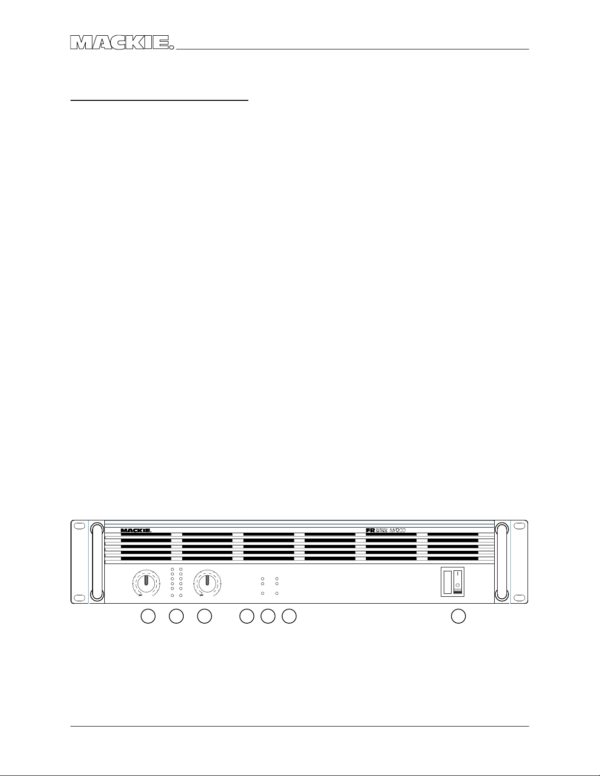
1. G AIN
De te nte d g a in c o ntro ls a d just the le ve l se nt to e a c h o utp ut se c tio n. The g a in struc ture
is de sig ne d so tha t a +4dBu (1.23V rms) inp ut sig na l drive s the a mp lifie r to full rate d
p o we r into 4Ω.
2. METERS
The M•1200/ M•1400’ s me ters indic ate the re la tive o utput le ve l o f the a mp lifie r
re fe re nc e d to full po w e r. The SIG (sig na l p re se nt) se nse s the inp ut p rio r to the g a in
c o ntro l.
3. PRO TEC T
The Pro tec t LEDs lig ht ind ic a ting the c ha nne l ha s b e e n mute d fo r o ne o f the fo llo w ing
re a so ns:
• 4 se c o nd turn o n d e la y
• O utp ut d e vic e s b e yo nd Sa fe O p e ra ting Are a (SO A), a lso lig hts SHO RT LED(s).
• He a tsink te m p e ra ture b e yo nd 80 d e g re e s Ce lsius.
M•1200/M•1400 SERVIC E MANUAL
4. SHO RT
The Sho rt LEDs lig ht to sho w tha t the a mp lifier ha s e ng a g e d p ro te c tio n d ue to a sho rt o r
lo w imp e da nc e o n the o utput.
5. TEMP STATUS
The HO T LED lig hts to ind ic a te tha t the a mp lifier ha s e ng a g e d p ro te c tio n d ue to
he a tsink te m p e ra ture o r p o we r tra nsfo rme r c o re te mp e ra ture .
6. PO WER SWITC H
This re ma rka b le d e vic e re q uire s ye ars o f stud y to full c o m p rehe nd.
PR OFE SS IO NA L POW ER AMP LIFIE RFULL S YMM ETRY D UAL D IFFER ENTI AL HI GH CU RRE NT DE SIGN
CH
GAIN/dB CH
OL
3v
1
20
2218
-3
2v
2
1
6
1
4
8
SENSITIVITY
30
1v
1.23v (+4dBu)
-6
4
26
-9
-2
28
0
SIG
GAIN/dB
O
3
L
-3
-6
14
-9
-2
0
SIG
SENSITIVIT
2
v
2
221
0
8
2
2416
v
2
6
2
8
8
3
0
1v
1.23v (+4dBu)
Y
1 12 3 4 5 6
CH1CH
INTERNALSTATUS
PROTECT
SHORT
TEMP STATUS
CH
1&2
COLDHOT
2
ON
OFF
POWER
4
SUMMA RY OF FEATURES
Page 7

VERSIO N 1.1
REAR PANEL
1. SPEAKER O UTPUTS
The M•1400 ha s Spe a ko n
mo d e ls ha ve b ind ing po sts. Fo r b ridg e d mo no o p e ra tio n, the + o utp ut c o m e s fro m
c ha nne l o ne ’s po sitive te rmina l a nd - fro m c ha nne l two ’s po sitive .
c o nne c to rs whe re the M•1200 ha s ¼” sp e aker o utp uts. Bo th
2. INPUT
The M•1200/ M•1400 ha s b o th XLR and ¼” TRS inp uts. The y a re e le c tric a lly ide ntic a l
(w ire d in p a ra lle l). In b rid g e d m o no o r p a ra lle l m o no mo d e c ha nne l 2 inp ut is d isa b le d .
3. THROUGH
Ye t a no the r ja c k wire d in p a ra lle l with the Inp uts, the thro ug h ja c k pro vid e s a
c o nve nie nt w a y to c ha in a m p lifie rs o r p a ss the sig na l to a ny o the r d e vic e .
4. LO W CUT FILTER
Swe e ps the b uilt in hig h p a ss filte r fro m 10Hz to 170Hz.
5. C O NSTANT DIREC TIVITY HO RN EQ / AIR EQ
Built in she lving EQ p ro vide s hig h fre q ue nc y c o mp e nsa tio n whe n using c o nsta nt
d ire c tivity ho rns.
6. AMP MO DE
Thre e po sitio n slid e switc h se le c ts STEREO , PARALLEL MO NO o r BRIDG E MO NO o p e ra tio n.
C ha nne l O ne ’ s inp ut sig na l is use d fo r PARALLEL MO NO a nd BRIDG E MO NO o pe ratio n.
AMP MODE a nd O UTPUT APPLIC ATIO N switc he s sho uld no t b e c ha ng e d while the unit is
o n.
7. O UTPUT APPLICATIO N
Pla c ing the thre e p o sitio n slid e switc h in its c e nte r p o sitio n d e fe a ts the b uilt in LIMITER fo r
b o th c ha nne ls. Se le c ting SUB WO O FER e ng ag e s the b uilt in lo w pa ss filte r. The
FREQ UENC Y switc h se le c ts b e twe e n 125Hz a nd 63Hz c uto ff fo r the lo w p a ss filte r. In SUB
WO O FER m o d e , inputs 1 a nd 2 a re summe d re g a rd le ss o f AMP MO DE se tting .
(Re m e mb e r, huma n he a ring is una b le to d isc e rn d ire c tio n a t fre q ue nc ie s whe re the
wa ve le nth is g rea te r tha n the dista nc e b e twe e n yo ur e a rs, ~250Hz unle ss yo u ha ve a
g ro ssly larg e he a d!)
(MONO BRIDGE)
1200 WATTS
4 OHM LOAD MIN.
600 W A TTS CH
2 OHMS LOAD MIN.
120 VAC 50/60 Hz
1500 WATTS
CAUTION
MONO
BRIDGE
+
+
SPEAKER OUTPUTS
-
CH
2
+
--
CH
1
1 5
4 62
/ BRIDGE / MONO
CHANNEL
LOW CUT
FILTER
BALANCED
O
TYPICAL
RUNBALANCED
35 Hz
STAGE
MONITOR
100 Hz
170 Hz
OFF
CONSTANT DIRECTIVITY
HORN EQ/AIR EQ
4.5
k
Hz
ON
6k Hz2k Hz
AIR EQ
OFF
TYPICAL
INPUT
3 7
STEREO
TYPICAL
OUTPUT APPLICATION
FULL
RANGE
(
CH1 & CH2)
LIMITER
STEREO
TYPICAL
ON
AMP MODE
MONO BRIDGE
OFF
WOOFER
SUB
FREQUENCY
125Hz
63Hz
2
THRUTHRU
4
CHANNEL
HORN EQ/AIR EQ
LOW CUT
FILTER
TYPICAL
21
35 Hz
STAGE
MONITOR
100 Hz
170 HzOFF
4.5k Hz
6k Hz2k Hz
AIR EQAIR EQ
AIR EQ
INPUT
BALANCED
O
UNBALANCED
R
CONSTANT DIRECTIVITY
ON
OFF
TYPICAL
53
SYSTEM OVERVIEW
5
Page 8

SPEC IFIC ATIO NS
M•1200/M•1400 SERVIC E MANUAL
C O NTINUO US AVERAG E O UTPUT
POWER, BO TH C HANNELS DRIVEN:
M• 120 0
225 wa tts pe r c ha nne l into 8 o hms fro m 20Hz to
20kHz, with no mo re tha n 0.025% THD
400 wa tts pe r c ha nne l into 4 o hms fro m 20Hz to
20kHz, with no mo re tha n 0.050% THD
600 wa tts pe r c ha nne l into 2 o hms fro m 20Hz to
20kHz, with no mo re tha n 0.095% THD
Bridg e d mono o p e ration:
800 wa tts into 8 o hm s fro m 20Hz to 20kHz, with
no mo re tha n 0.050% THD
1200 wa tts into 4 o hms fro m 20Hz to 20kHz, w ith
no mo re tha n 0.095% THD
Ma ximum Po w e r a t 1% THD:
250 wa tts p e r c ha nne l into 8 o hms
425 wa tts p e r c ha nne l into 4 o hms
640 wa tts p e r c ha nne l into 2 o hms
850 wa tts into 8 o hms b rid g e d
1280 wa tts into 4 o hms b rid g e d
M• 140 0 / M• 140 0i
250 wa tts pe r c ha nne l into 8 o hms fro m 20Hz to
20kHz, with no mo re tha n 0.012% THD
425 wa tts pe r c ha nne l into 4 o hms fro m 20Hz to
20kHz, with no mo re tha n 0.025% THD
630 wa tts pe r c ha nne l into 2 o hms fro m 20Hz to
20kHz, with no mo re tha n 0.050% THD
Bridg e d mo no o p e ra tio n:
850 wa tts into 8 o hm s fro m 20Hz to 20kHz, with
no mo re tha n 0.025% THD
1260 wa tts into 4 o hms fro m 20Hz to 20kHz, w ith
no mo re tha n 0.050% THD
Ma ximum Po we r a t 1% THD:
300 wa tts p e r c ha nne l into 8 o hms
500 wa tts p e r c ha nne l into 4 o hms
700 wa tts p e r c ha nne l into 2 o hms
1000 wa tts into 8 o hms b rid g e d
1400 wa tts into 4 o hms b rid g e d
No te: Po w e r ra ting s a re sp e c ifie d a t
120VAC (U.S. a nd C a na d a ) a nd 240VAC
(Expo rt) line vo lta g e s.
The M•1200/ M•1400 p o we r a m p lifie rs d ra w
la rg e a mo unts o f c urre nt fro m the AC line with
c o ntinuo us sine wa ve te sting . A c c ura te
me a sure m e nt o f p o we r re q uire s a stea d y a nd
sta b le AC sup p ly. This me ans the line
imp e d a nc e m ust b e ve ry lo w to insure tha t the
p e a k AC line vo lta g e do e s no t sa g to le ss tha n
97% o f its va lue .
If d riving hig hly re a c tive lo a ds, w e re c o mme nd
tha t the lim ite r c irc uit b e e ng ag e d.
POWER BANDWIDTH:
20Hz to 70kHz (+0, –3 dB)
FREQ UENC Y RESPONSE:
20Hz to 40kHz (+0, –1 dB)
10Hz to 70kHz (+0, –3 dB)
DISTO RTIO N:
THD, SMPTE IMD, TIM < 0.025% @ 8Ω
< 0.050% @ 4Ω
< 0.150% @ 2Ω
SIGNAL-TO -NOISE RATIO :
> 107 d B be lo w ra te d p o we r into 4 o hms
C HANNEL SEPARATIO N:
> 80 d B @ 1kHz
DAMPING FAC TOR:
350 minimum
INPUT IMPEDANC E:
20k b a la nc e d b rid g ing
INPUT SENSITIVITY:
1.23 vo lts (+4 d Bu) fo r ra te d p o we r into 4 o hms
G AIN:
30.25 d B (32.5V/ V)
MAXIMUM INPUT LEVEL:
9.75 vo lts (+22 d Bu)
6
SPEC IFIC ATIO NS
Page 9

VERSIO N 1.1
RISE TIME:
< 4.4µs
SLEW RATE:
Vo lta g e Sle w Rate > 50V/ µs
> 100V/ µs b rid g e d
C urre nt Sle w Rate > 32A/ µs a t 2Ω
C MRR:
> 40 d B, 20Hz to 20kHz
LO AD ANGLE:
8(±jx) time ind e pe nd e nt a t 8Ω
4(±jx) time d e p end e nt, T > 6 min. a t 4Ω
2(1±jx) time d e p e nde nt, T > 2 m in. a t 2Ω
TRANSIENT RECO VERY:
< 1µs fo r 20 dB o ve rdrive @ 1kHz
HIG H FREQUENCY O VERLOAD AND
LATC HING:
No latc h up a t a ny fre q ue nc y o r le ve l.
HIG H FREQUENCY STABILITY:
Unc o nd itio na lly sta b le d riving a ny re a c tive o r
c ap a c itive lo ad .
TURN ON DELAY:
3 se c o nd s
LIMITER SEC TIO N:
C o mp le me ntary Po sitive a nd Ne g ative Pe a k
De te c ting
INDICATO RS:
6 m e te r LEDs p e r c ha nne l
SIG (Sig na l Pre se nt), –20, –9, –6, –3, O L
(O v e rlo a d )
C H 1 & 2
PROTEC T LEDs
SHO RT LEDs
TEMP STATUS
C O LD/ HO T LEDs
POWER CO NSUMPTIO N:
65 wa tts a t id le
900 wa tts w ith m usic al p ro g ra m fully lo a de d
(2 o hms p e r sid e , o r 4 o hms b rid g e d )
550 wa tts w ith m usic al p ro g ra m fully lo a de d
(4 o hms p e r sid e , o r 8 o hms b rid g e d )
850 wa tts a t full p o we r into 8 o hms
(c o ntinuo us sine w a ve )
1500 wa tts a t full p o we r into 4 o hms
(c o ntinuo us sine w a ve )
2500 wa tts a t full p o we r into 2 o hms
(c o ntinuo us sine w a ve )
AC LINE PO WER:
US 120VAC , 60Hz
Euro pe 240VAC , 50/ 60Hz
Jap a n 100VAC , 50/ 60Hz
Ko re a 220VAC , 60Hz
VARIABLE LO W-C UT FILTER:
10Hz (Off) to 170Hz, 2nd Orde r Be ssel
SUBWO O FER LOW-PASS FILTER:
Switc he d : 63Hz/125Hz, 3rd Ord e r Be sse l
C O NSTANT DIRECTIVITY HIG H
FREQ UENC Y BO O ST:
2kHz to 6kHz (+3 dB p o ints)
6 d B/ o c tave hig h-freq ue nc y she lving filter,
(she lving o c c urs a t a p p ro xima te ly 30kHz)
AC DRO P-O UT VO LTAG E:
At a p p ro xima te ly 50% o f ra te d line vo lta g e
PHYSICAL:
He ig ht 3.5 inc he s (89mm)
Width 19.0 inc he s (483mm)
De p th 15.25 inc he s (387mm)
O ve ra ll De p th 16.25 inc he s (413mm )
Ha nd le De p th 1.25 inc he s (32mm)
We ig ht 36 p o und s (16.3kg )
Sinc e w e are a lw a ys striving to ma ke o ur stuff
b e tte r at Ma c kie De sig ns b y inc o rpo ra ting ne w
a nd imp ro v e d ma te ria ls, c o m p o ne nts, a nd
ma nufa c turing m e tho ds, w e re se rve the right to
c ha ng e the se sp e c ific a tio ns a t a ny time
witho ut no tic e .
SPEC IFIC ATIO NS
7
Page 10

C IRC UIT THEO RY
Muc h o f the c irc uitry in the M•1200/ M•1400 is se lf e xp la na to ry fro m the sc he ma tic . This
se c tio n will e xp lain the uniq ue c irc uits a nd a rc hite c ture. Samp les in this se c tio n will re fer
to C ha nne l 1 (Le ft) fo r c irc uitry tha t is id e ntic a l o n b o th c ha nne ls.
INPUT C IRC UITRY
Re fe r to sc he ma tic o n p a g e 23.
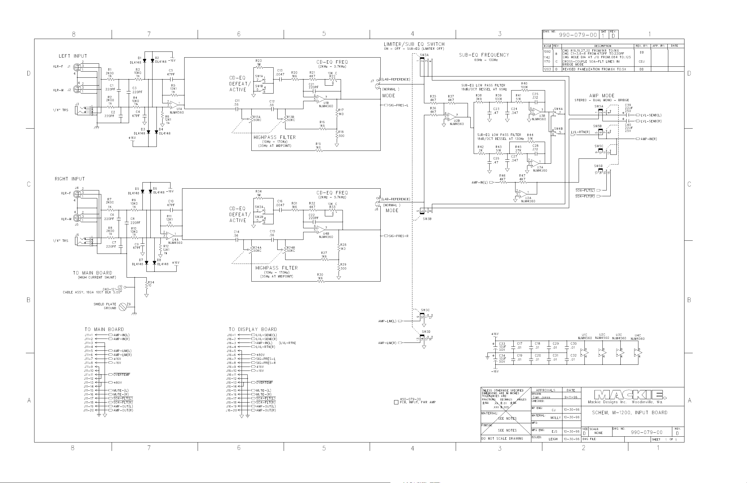
The sig na l p a th b e g ins with the INPUT BO ARD. Fo llo wing C ha nne l 1’ s inp ut, sig na l is fe d
to a unity g a in d iffe re ntia l o p -a mp , U1A . The sig na l is ne xt se nt to U1B whic h se rve s a s
b o th HPF a nd C D ho rn EQ. If no t in SUBWO O FER m o d e , the sum ming a m p (U2B) a nd
LPF’ s (U3A, U3B) a re b yp a sse d . The sig na l is se nt via J11 to the ga in c o ntro l o n the
DISPLAY BOARD. Afte r the g a in c o ntro l, the sig na l is b uffe re d b y U7A, returne d to the
INPUT BO ARD a nd ro ute d to the MAIN BO ARD via J16.
C ha nne l 2’ s inp ut sig na l pa th is e le c tric ally id e ntic a l to C ha nne l 1’ s in STEREO m o d e . In
PARALLEL MO NO m o de C ha nne l 2’ s inp ut sig na l is ig no re d a nd C ha nne l 1’ s inp ut is se nt
to C ha nne l 2’ s g a in c o ntro l via SW5A. Fo r BRIDG E MO NO o pe ratio n, C ha nne l 1’ s inp ut
sig na l is inve rte d b y U2A a nd ro ute d to the MAIN BO ARD via SW5C .
M•1200/M•1400 SERVIC E MANUAL
PO WER AMPLIFIER CIRC UITRY
Re fe r to sc he ma tic o n p a g e 27.
The M•1200/ M•1400 use a c la ss AB trip le d a rling to n o utput with c o m p le me nta ry o utput
d e vic e s. The m a in p o we r sup p ly is +/ - 80V, the re is a lso a +/ - 90V sup p ly fo r the fro nt
e nd c irc uitry. C ha nne ls are mute d fo r 4 se c o nd s o n p o we r up a s C53 c ha rg e s via R203.
Muting is a c hie ve d b y turning o ff Q73, re mo ving c urre nt so urc e s fo r the diffe rentia l pa irs.
(Wa it a minute ! PAIRS? Re a d o n…)
An imme d ia te ly o b vio us d e pa rture fro m sta nd a rd d e sig ns is the Dua l Diffe re ntia ls a nd
Symme tric al Vo lta g e Am p s. The re a so ning b e hind this fro nt e nd a rc hite c ture is
a c tua lly q uite simple . Tra nsisto rs tra nsfe r c ha ra c te ristic s a re no t e ntire ly line a r, so e ve n
the b e st c o nve ntio na l fro nt e nd d e sig n will intro duc e so me d isto rtio n. Mo st a mp lifie rs
use ne g a tive fe e db a c k to re duc e this p ro b le m (c re a ting a fe w m o re in the p ro c e ss).
Ma c kie FR Se rie s a m p lifie rs ta ke a d iffe re nt a p p ro a c h. By using two c o m p le m e nta ry
“ m irro r ima g e ” fro nt e nd c irc uits a ny d isto rtio n c ause d b y no n-line a r tra nsisto r c urve s is
e ffe c tive ly c anc e le d o ut in the b ia s string , w itho ut fe e db a c k!
Ano the r d e sig n fe a ture uniq ue to Ma c kie FR Se rie s Am p lifie rs is the Ba ke r C la m p . The
Ba ke r C la m p ha s two func tio ns; 1) Pre ve nt o utp ut/ d rive r tra nsisto rs sa tura ting , 2) Drive
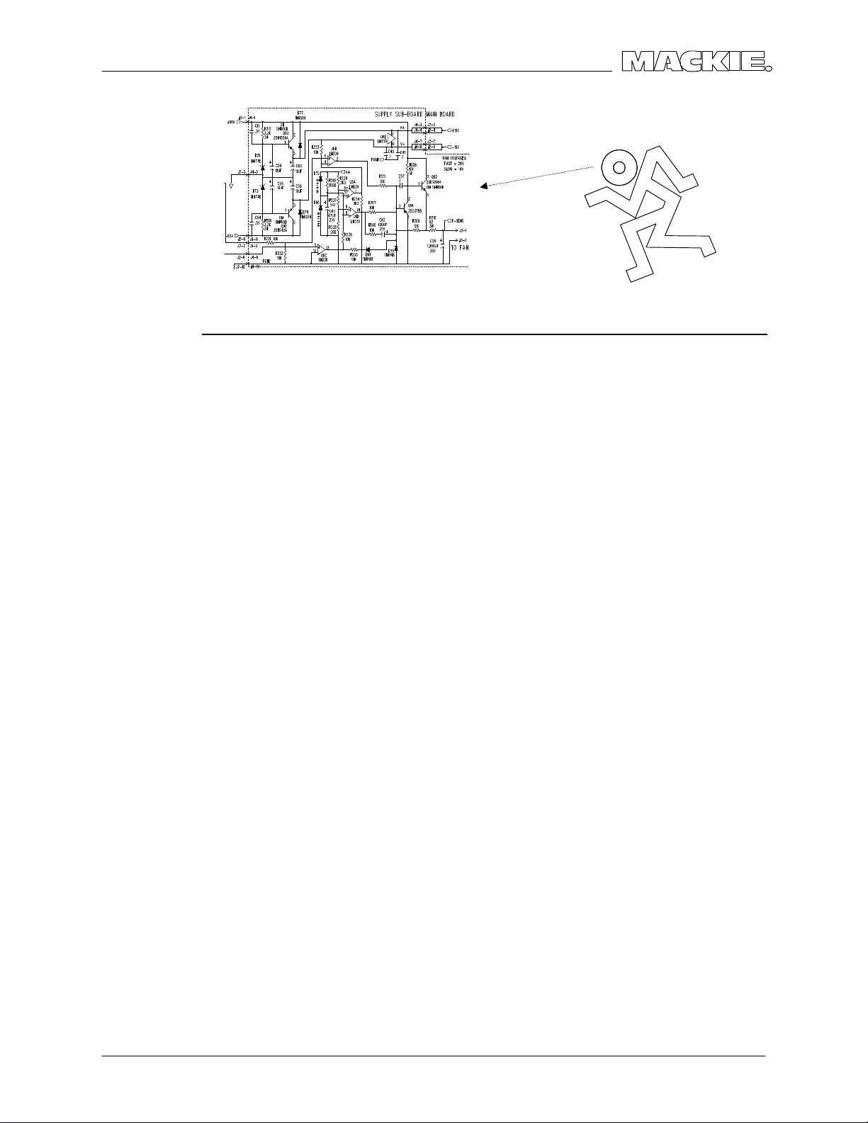
the LIMITER LDR. Re fe rring to the le ft ma in a m p sc he m a tic , Q27 is a c o m m o n b a se
a m p lifie r, it will turn o n if Q 31’ s c o lle c to r rise s mo re tha n two dio d e dro p s a b o ve the
+80V sup p ly, p re ve nting it fro m rising furthe r. The re a re thre e d io d e d ro p s b e twe e n
Q 31’ s c o lle c to r a nd the b a se o f drive r tra nsisto r Q 28 (D3, D2, Q29V
se e a vo lta g e g re a te r tha n o ne dio d e dro p b e lo w the +80V sup p ly, e ve n if the +80V
supp ly fluc tua te s. Q 27 a lso drive s the lim ite r LDR LED U2A. The ne g ative sid e ha s the
same c irc uit mirro re d .
). Q 29 will ne ve r
b e
8
C IRCUIT THEO RY
Page 11

VERSIO N 1.1
PRO TECTIO N CIRC UITS
Re fe r to sc he ma tic s o n pa g e s 27-29.
The M•1200/ M•1400 ha s two o utput p ro te c tio n c irc uits in a d d itio n to the ra il fuse s. The
first mute s the a m p if the o utput d e vic e s a re lo a d e d b e yo nd the ir safe o p e ra ting a re a
(SOA). The se c o nd is a c ro wb a r c irc uit tha t e nsure s the ra il fuse s b lo w if the re is DC o n
the o utp ut.
SOA PRO TEC TIO N
The SO A p ro te c tio n c irc uit se nse s the vo lta g e dro p a c ro ss the e mitte r re sisto rs muc h like
sta nd a rd VI c urrent limiting tra nsisto rs. Q 76 a nd Q 77 will turn o n if the e m itte r d ro p
e xc e ed s ~1V. If the y a re o n fo r lo ng e no ug h to c ha rg e C38 (thro ug h R159) , the SO A
p ro te c tio n c irc uit is a c tiva te d b y tra nsisto r sw itc he s Q 79 a nd Q 78.
If SOA d e te c tio n is tripp e d, the c ha nne l is mute d b y d isc ha rg ing C 53 thro ug h R200 a nd
D65, fa n sp e e d is inc re a se d , a nd the “ SHO RT” LED lig hts.
DC CRO WBARS
The DC Cro w b a r c irc uit pro te c ts spe a ke rs in the e ve nt o f a n o utput fa ilure b y b lo wing
a ll rail fuse s. SC Rs Q 21-24 a re use d to sho rt the +/ - 80V sup p ly supp lie s to g ro und .
O utp ut sig na l fro m b o th sid e s is fe d thro ug h 100K re sisto rs R90, R89 to C 21, e sse ntia lly
fo rming a LPF. DC o n e ithe r o utput will trig g e r c o m p a ra to r U4A (po sitive ) o r U4B
(ne g ative ). The SCRs are the n fire d via d rive r tra nsisto rs Q87, Q 88.
NOTE:
The LM339 c o m p a ra to r IC is use d e xte nsive ly in the
M•1200/ M•1400. It diffe rs fro m a sta nd a rd o p -a mp
use d a s a c o mp a ra to r in tha t it ha s a n o pe n
c o lle c to r o utp ut. If the vo lta g e a t the inve rting input
e xc e ed s the no n-inve rting , the LM339’ s o utp ut
switc he s to it’ s ne g a tive sup p ly. Othe rwise , the
o utp ut is o p e n.
C IRCUIT THEO RY
9
Page 12

THERMAL MANAG EMENT
Re fe r to sc he ma tic o n p a g e 29.
The M•1200/ M•1400 T-De sig n He a tsink/ Fa n c o o ls o utp ut de vic e s e ve nly a nd d o e s no t
c o lle c t dust o n the c irc uitry. The fa n o pe ra te s a t two sp e e d s, c o ntro lle d b y the
a m p lifie r. An LM35DZ mo unte d in the c e nte r o f the he a tsink p ro vide s te m p e ra ture
info rma tio n to the fa n c o ntro l a nd o ve rte mp c irc uits. The re is a lso a the rma l b re a ke r in
the p o we r tra nsfo rme r.
FAN CO NTRO L C IRC UIT
The fa n vo lta g e c o me s fro m a fe e d b a c k re g ula to r c irc uit fo rme d b y Q 91 a nd Q 92. The
o utp ut vo lta g e is p ro g ra m m e d b y the ra tio o f R209 to R211/ / R207 (/ / =p a ra lle l). Whe n
the unit is p o we re d up C 83 c ha rg e s thro ug h R241 p ro viding a 40 sec o nd d e la y b e fo re
the fa n sta rts. As C83 c ha rg e s, U6D’ s o utput switc he s to -16V, sta rting the fa n. The n
U6A’ s o utp ut switc he s to o pe n, a llo w ing U6B to inc re a se the fa n sp e e d , if trig ge re d . R240
a nd C 82 g ive the fa n e xtra vo ltag e whe n starting .
The fa n sp e e d is inc re a se d b y U6B a dd ing R211 in p a ra lle l w ith R207. (Q 91 w a nts it’s
b a se a dio d e dro p a b o ve g ro und , so Q 92 d o ub le s its Em itte r vo lta g e ). U6B is trigg e re d
b y U4D to inc re a se fa n sp e e d if;
M•1200/M•1400 SERVIC E MANUAL
• C ha nne l 1 SOA p ro te c tio n is ac tiva te d (U5C ), O R
• C ha nne l 2 SOA p ro te c tio n is ac tiva te d (U5D), O R
• The he a tsink is a b o ve 60 d e g C ( U5B) A ND p ro g ra m is d e te c te d (U4C ), O R
• The he a tsink te m p e ra ture is a b o ve 80 d e g C ( U5A).
U6C a nd Q 89 a re use d to re se t the c irc uit o n po we r d o wn. Und e r no rm a l o p e ra tio n
C 50 is c ha rg e d via D57, Ho lding Q 89 o ff. Whe n p o w e r is re mo ve d C 50 d isc ha rg e s a nd
Q 89 switc he s o n a s the ra ils c o lla p se . Whe n the vo lta g e o n Q89’ s c o lle c to r fa lls be lo w
g ro und U6 switc he s to the ne g a tive ra il d isc ha rg ing C 82 a nd C 83.
THERMAL SHUTDO WN
Extre me he a tsink o r tra nsfo rme r c o re te m p e ra ture will a c tiva te O VERTEMP. U5A
a c tiva te s o ve rte mp if the LM35DZ de te c ts he a tsink te m p e ra ture a b o ve 80 d e g C .
Fe e d b ac k re sisto r R137 re sc ale s U5A ’ s vo lta g e re fe re nc e so tha t the he a tsink must c o o l
to b e lo w 50 d e g C b efo re o ve rte m p is d e a c tiva te d . O ve rte m p c a n a lso b e a c tiva te d
b y the p o we r tra nsfo rme r the rma l b re a ke r (via Q 89) . In e ithe r c a se , b o th c ha nne l a re
mute d via D69 a nd D66.
10
C IRCUIT THEO RY
Page 13

VERSIO N 1.1
SERVIC E PRO C EDURES
MEC HANIC AL PRO C EDURES
The M•1200/ M•1400 d e sig n a llo ws e a sy re mo va l o f all c o m p o ne nts a nd a sse m b lie s.
Disasse m b ly a nd re a sse mb ly sho uld b e se lf e vid e nt. This m a nua l ha s e xplo d e d
d iag rams in the pa rts se c tio n.
Se ve ra l imp o rta nt p o ints c o nc e rning the asse mb ly:
• 4 o f the sc re w s tha t se c ure the to p c o ve r a lso ho ld the fro nt e xtrusio n ( c urve d
p iec e ) in p la c e . Whe n re mo ving the to p c o ve r, b e c a re ful tha t the fro nt e xtrusio n is
no t d ro p p e d.
• If the MAIN PC B is re mo ve d , b e sure the sma lle r he a d ma c hine sc re w s (750-050-04)
a re re p lac e d ne xt to the filte r c ap s. The la rg e r he a d m a c hine sc re w s c an a rc to the
c ap a c ito r b o dy.
• Be sure a ll tywra p s a re re pla c e d a nd tha t no wire s a re in d a ng e r o f b e ing p inc he d
in-b e twe e n the c o ve r a nd he a tsink.
REQ UIRED EQ UIPMENT LIST
• 30 MHz dua l tra c e o sc illo sc o p e
• DMM ( Must b e c a p a b le o f m e a suring 8m V DC with a minim um o f 2 d ig its o f
a c c ura c y, a nd d o wn to .1Ω)
• Sine w a ve o sc illa to r / Func tio n g ene ra to r (20Hz - 20KHz)
• 4 lo a d re sisto rs (8Ω with a m inim um 500W p o we r ra ting )
• 10A / 120V Va ria c With AC vo ltm e te r a nd a d e fe a ta b le a mme te r (1 Amp full ra ng e )
o r wa ttme te r (300 Wa tts full rang e )
• 0.1uF 400V film c a p a c ito r insta lle d a c ro ss dua l b a na na p lug
• 16 A WG sho rting jump e r installe d a c ro ss d ua l b a na na p lug
REC O MMENDED EQ UIPMENT LIST (PERFO RMANCE VERIFICATIO N)
• Disto rtio n a na lyzer a nd lo w d isto rtio n o sc illa to r.
(C a p a b le o f re so lving d isto rtio n a s lo w a s 0.002% fro m 20Hz to 20KHz)
• 2500W AC p o we r so urc e .
SERVIC E PRO C EDURES
11
Page 14

M•1200/M•1400 SERVIC E MANUAL
TRO UBLESHO O TING TIPS - O UTPUT FAILURES
Afte r a c a ta stro phic fa ilure , it is like ly tha t the fo ur +/ -80V sup p ly fuses will b e b lo w n.
Re p lac e fuse s a nd ve ry slowly b ring up the Va ria c while m o nito ring line c o nsum p tio n. It
is like ly tha t sub sta ntia l line c urre nt will be p ulle d due to sho rte d o utput p a rts. At the
same time , lo o k fo r DC o ffse t a t the o utp ut. O ffse t o f g re a te r tha n +/ - 2.8V w ill trig g e r
the p ro te c tio n c irc uits a nd re -b lo w the fo ur fuse s. Ke e p the o utput o ffse t b e lo w +/ - 2V,
o r te m p o ra rily d e fe a t the DC-o ffse t d e te c to r (Lift o ne sid e o f D56).
Re mo ve the ma in b o a rd fro m the unit a nd c he c k fo r sho rte d o utput tra nsisto rs. If o ne
b a d o utp ut is fo und , re p lac e a ll e ight in the c ha nne l. Whe n a n o utput d e vic e sho rts it
c an p la c e hig h c urre nt stre sse s o n the o the r o utp ut pa rts. The se o utput p a rts c a n fa il
o ve r time . Sinc e lo ng te rm re liab ility is p a ra mo unt, ple a se re p lac e a ll the o utputs.
All e ig ht o f the 3W 0.22Ω e m itte r re sisto rs must b e ve rifie d fo r pro pe r va lue . Any o ff-
to le ra nc e, o r o p e n p a rts, ne e d to b e re p la c e d . An o ff to le ra nc e (hig he r re sista nc e )
e mitte r re sisto r will p re ve nt it’ s re la te d o utput tra nsisto r fro m “ d o ing it’ s sha re ” a nd w ill
p lac e m o re stre ss o n it’ s ma te s in the o utp ut se c tio n. Also ve rify the 8 b a se d rive re sisto rs
(2.2Ω, 1/ 4W, fusib le ) a re a ll O K. Ve rify tha t the d rive rs and p re-d rive rs a re no t sho rte d . If
o ne drive r is sho rte d re p lac e it’ s ma te . Do the sa m e with the p re -d rive rs. Also c he c k a ll
the re sisto rs surro und ing the drive rs and p re -d rive rs.
C he c k the VI limite rs a nd d e te c to rs. It is no t unc o m m o n to d a m a ge the se p a rts whe n
the a mp lifie r fa ils in a sp e c ta c ula r w a y! Lo o k fo r sho rts o n Q76, Q77, Q 94, Q 95, Q 83,
Q 84, Q 96, a nd Q 97. Ve rify p ro p e r va lue o n the re sisto rs tha t g o to the b a se s o f the se
d e vic e s. It is c ritic a l tha t the se se c tio ns a re wo rking c o rre c tly. Sho rte d tra nsisto rs c a n
c ause so m e o dd a symme tric al c lipp ing pro b le m s. O p e n p a rts will no t a llo w the c urre nt
limiting to o pe ra te e ffe c tive ly. If p ro b le ms e xist in the se se c tio ns the amp lifie r mig ht fa il
into a sho rt, o r m ig ht c lip p re m a ture ly w he n lo a d e d to 2Ω.
All o f the a bo ve tro ub le sho o ting (No t inc lud ing p a rt re p la c e me nt) takes pe rha p s 15 to
30 m inute s to d o . If yo u ta ke the time , a nd d o a ll tha t is ind ic a te d a bo ve , it will allo w
99% o f the a mp lifie rs to c o me up the first time ! Trying to hurry, a nd skip p ing w ha t is
sug g e ste d , c an lea d to a frustra ting a nd time c o nsum ing re p a ir.
Slo w ly b ring up the sup p ly a nd ve rify tha t line c o nsump tio n isn’ t e xc e ssive a nd tha t the
o utp ut is c e nte re d (no DC o ffse t). It mig ht b e d e sira ble to d e fe a t the a mp lifie r muting
(C o nne c t U5-12, 13, & 14 to g e the r) te m p o ra rily so the a m p lifie rs are a c tive e ve n w he n
the sup p lie s a re still ve ry lo w. If the a m p sta ys c e nte re d , ve rify tha t it will pa ss a nic e
c le an sine w a ve . Re mo ve a ny te st jum p e rs (I.E. DC -fa ult d e fe a t & muting d e fe a t) a nd
p ro c e e d to the “ Re lia b ility Ve rific atio n” se c tio n.
12
SERVIC E PRO C EDURES
Page 15

VERSIO N 1.1
BIAS AND TEST PRO C EDURE
Afte r the unit ha s b e e n re pa ire d , the fo llo wing sho uld b e d o ne to a ssure lo ng te rm
re lia b le o p e ra tio n. If a d isto rtio n a na lyze r is pre se nt, d isto rtio n spe c ific atio ns sho uld b e
ve rifie d .
1. Ad justs bia s in b o th c ha nne ls (R1 & R51) fo r 8m V +/ - 0.3mV a t b ia s te st po ints (J53 &
J54) a fte r unit ha s id le d fo r a fe w m inute s. With Full AC line vo lta g e a p p lie d to unit,
it will p ull a ro und 65W fro m the line (900mA a t 120V). Me a sure fo r DC o ffse t o n b o th
o utp ut c o nne c to rs. DC o ffse t sho uld b e less tha n +/ - 50m V.
2. Ap p ly a 1KHz sine w a ve to the inputs a nd ve rify tha t the unlo a d e d o utp uts ha ve a
wa ve fo rm tha t is sym m e tric a l a nd und isto rte d . Drive the o utputs into c lipp ing a nd
ve rify symme tric a l “fla t-to p p ing ” o n the wa ve fo rm.
3. Re d uc e o utput le ve ls, install the 0.1uF c a p a c ito r jump e r fro m the o utp ut to g ro und
c o nne c tio ns, a nd ve rify tha t c lipp ing be ha vio r is p ro p e r. Ve rify tha t no hig h
fre q ue nc y o sc illa tio n o c c urs ne ar a nd a t c lipp ing (p a ra sitic o sc illa tio n).
4. Re m o ve c a p a c itive lo a d ing a nd m inimize sine o utp ut. Ve rify a nd re -a d just b ia s if
re q uire d . No te tha t the b ia s will no t d rift a p p re c ia bly in a unit tha t is func tio ning
p ro p e rly.
5. C o nne c t the a m p lifie r d ire c tly to the AC line a nd c o nne c t a n 8Ω d ummy lo a d to
b o th c ha nne ls. Bring sine w a ve le ve l up o n b o th c ha nne ls a nd ve rify sym m e tric a l
c lipp ing . The o utput will c lip so m e w he re b e twe e n 120V - 140V p k/ p k de p e nd ing o n
ho w stiff the line is. C lip p ing sho uld b e a s de sc rib e d a b o ve . Ad d the 0.1uF
c ap a c itive lo a d ing a nd ve rify c lip p ing is still we ll b e ha ve d .
6. Ind ivid ua lly lo a d Cha nne l 1 a nd C ha nne l 2 with 2Ω. Clip p ing sho uld b e
symme tric al, we ll b e ha ve d , a nd o c c ur so m e w he re a ro und 80V - 100V p k/ p k. Ve rify
tha t c lipp ing is we ll b e ha ve d a fte r a d d ing the 0.1uF c a p a c itive lo a d ing .
7. Re d uc e o utput le ve l to 20V p k/ p k a nd sho rt first c ha nne l o ne a nd the n c ha nne l
two . The fro nt p a ne l “sho rt” a nd “ p ro te c t” LEDs sho uld fla sh o n the re sp e c tive
c ha nne ls.
8. Pla c e a mp lifie r in b rid g e m o de a nd c o nne c t 4Ω lo a d ing to brid g e o utputs (a c ro ss
b o th “ +” o utp ut b ind ing po sts). Slip so me c a rd sto c k b e twe e n the he atsink-o utle ts
a nd c ha ssis sid e s. Mo nito r o ne o f the o utputs a nd a d just fo r a 20V p k/ p k sig na l.
Sho rt a c ro ss b o th o utputs and ve rify tha t a ll fo ur ‘ Sho rt” a nd “ Pro te c t” LEDs lig ht and
the a mp lifie r mute s.
9. Re m o ve sho rt, mo nito r o ne o f the o utputs, a nd a d just fo r a 60V p k/ p k sine o utput
(450W o f o utput p o we r b rid g e d ). Afte r a fe w m inute s the fa n w ill be g in running fa st
(he a tsink a t 60°C ) a nd a sho rt tim e late r the a m p lifie r w ill mute (he a tsink a t 80°C).
The “ Ho t” a nd “ p ro te c t” LEDs w ill c o m e o n. Re m o ve c a rd sto c k a nd a fte r a fe w
minute s the a m p lifie r will c o m e o ut o f m ute mo de a nd the “c o ld ” LED will re turn.
10. Disc o nne c t lo ad ing a nd re m o ve drive . Re c o nne c t a m p lifie r to Va ria c a nd c o nfirm
tha t the id le c o nsump tio n is ro ug hly 65W o r 900mA, a s b e fo re . C o nne c t the
a m p lifie r to sp e ake rs a nd ve rify tha t it so und s OK w ith m usic .
SERVIC E PRO C EDURES
13
Page 16

M•1200/M•1400 SERVIC E MANUAL
(THIS PAG E UNINTENTIONALLY LEFT BLANK), THO SE RESPONSIBLE HAVE BEEN PUT TO THE SWO RD
14
SERVIC E PRO C EDURES
Page 17

VERSIO N 1.1
PARTS
Q UICK PARTS
FRO NT PANEL
CH
GAIN/dB CH
3v
1
20
2218
2v
2
1
4
6
26
1
4
28
8
30
1v
1.23v (+4dBu)
SENSITIVITY
PR OFE SS IO NA L POW ER AMP LIFIE RFULL S YMM ETRY D UAL D IFFER ENTI AL HI GH CU RRE NT DE SIGN
OL
-3
-6
-9
-2
0
SIG
3
L
-3
-6
14
-9
-2
0
SIG
SENSITIVIT
2
v
2
1
2
0
8
2
2
2416
v
2
6
8
2
8
3
0
1v
1.23v (+4dBu)
Y
GAIN/dB
O
CH1CH
INTERNALSTATUS
PROTECT
SHORT
TEMP STATUS
CH
1&2
COLDHOT
2
ON
OFF
POWER
HANDLE ASSEMBLYS
RIG HT, 080-023-10
LEFT, 080-023-20
SC REW(TO C HASSIS),700-028-04
REAR PANEL
(MONO BRIDGE)
1200 WATTS
4 OHM LOAD MIN.
600 W A TTS CH
2 OHMS LOAD MIN.
120 VAC 50/60 Hz
1500 WATTS
AC LINE C ORD
US, 640-006-00
EURO PE, 640-007-01
JAPAN, 640-007-02
ENGLAND, 640-007-03
ITALY, 640-007-04
AUSTRALIA, 640-007-05
SWITZERLAND, 640-007-06
STRAIN RELIEF
740-004-00
INTERNA L FUSES
RAIL FUSES;
10A 5X20MM, 510-021-00
MAIN FUSE;
20A, 510-017-00
8A, 510-023-00
G AIN C O NTRO LS
5KL PO T, 130-036-00
KNOB, 760-061-00
NUT, 705-013-00
ALL LEDS
RED T-1, 304-001-00
G REEN T-1, 304-004-00
PO WER SWITCH
500-022-00
STAR WASHER, 710-023-00
CAUTION
MONO
BRIDGE
+
-
CH
1
+
CH
2
+
--
SPEAKER OUTPUTS
SPEA KER O UTPUTS
BINDING POSTS, 400-119-00
BINDING POST SCREW, 700-011-00
CHANNEL
OFF
/ BRIDGE / MONO
LOW CUT
FILTER
TYPICAL
35 Hz
STAGE
MONITOR
100 Hz
170 Hz
CONSTANT DIRECTIVITY
HORN EQ/AIR EQ
k
Hz
4.5
6k Hz2k Hz
AIR EQ
BALANCED
INPUT
O
RUNBALANCED
ON
OFF
TYPICAL
STEREO
TYPICAL
OUTPUT APPLICATION
FULL
RANGE
(
CH1 & CH2)
LIMITER
STEREO
TYPICAL
ON
AMP MODE
MONO BRIDGE
OFF
WOOFER
SUB
FREQUENCY
125Hz
63Hz
INPUT SEC TIO N
ALL KNO BS, 760-048-04
LO W CUT, 50KZx2 POT, 130-017-02
INPUT
THRUTHRU
BALANCED
UNBALANCED
TYPICAL
O
R
ON
OFF
CHANNEL
CONSTANT DIRECTIVITY
HORN EQ/AIR EQ
LOW CUT
FILTER
TYPICAL
21
35 Hz
STAGE
MONITOR
100 Hz
170 HzOFF
4.5k Hz
6k Hz2k Hz
AIR EQ
AIR EQAIR EQ
C D HO RN EQ , 10KC PO T, 130-037-02
M• 12 00 / M•1400i
¼” JAC K, 400-118-00
WASHER, 710-019-00
SLOTTED NUT, 705-015-00
M• 14 00
SPEA KON, 400-138-00
SC REW, 700-055-00
¼” INPUT JACK, 400-214-00
¼” JAC K WASHER, 710-002-00
¼” JAC K NUT, 705-003-00
MALE XLR JAC K, 400-142-00
FEMA LE XLR JAC K, 400-141-00
XLR JAC K SCREWS,700-055-00
DP3T SWITC HES, 500-023-00
DPDT SWITC HES, 500-024-00
PARTS
15
Page 18

C HASSIS ASSEMBLY
M•1200/M•1400 SERVIC E MANUAL
1
4
1 7
2
3
16 17 18
5
6
15
16
10
14
13
8
9
11
12
PARTS
1
Page 19

VERSIO N 1.1
C HASSIS ASSEMBLY PARTS LIST
ITEM # PART # DESCRIPTIO N NOTES
1 700-028-02 SEMS 6-32X3/ 8 PHP BLKZC ALL SIDE PANEL SCREWS
2 550-221-00 TO P C O VER - M1200
3 700-041-04 MC H 6-32X3/ 8 FL 100DG BLK TO P C O VER TO CHASSIS
4 551-029-00 EXTR SC RN DSPLY BZL-M1200
4 551-029-10 EXTR SC RN DSPLY BZL-M1400
5 700-041-04 MC H 6-32X3/ 8 FL 100DG BLK MANIFOLD TO FA N
6 550-277-00 SC REEN MANIFO LD - M1400
7 550-223-20 SIDE RAIL LEFT - M1200
8 550-223-10 SIDE RAIL RIGHT - M1200
9 550-222-00 BTM C OVER - M1200
9 550-244-00 BO TTO M COVER - M1400
10 080-023-20 PNT HANDLE ASSY LEFT
11 080-023-10 PNT HANDLE ASSY RIG HT
700-028-04 SEMS 6-32X3/ 4 PHP BLKZC HANDLE ASSY TO CHASSIS
700-041-04 MC H 6-32X3/ 8 FL 100DG BLK HEATSINK TO C HASSIS BO TTTO M
12 TRANSFORMER / MO UNTING
600-016-00 XFMR M1200 120V
600-016-01 XFMR M1200 230V
600-016-02 XFMR M1200 100V
705-019-00 NUT HEX 5/ 16-18
710-017-00 WASH SPLTLC K 5/ 16 HEAVY
710-024-00 WASH FLAT 5/ 16 HARD (USS)
550-249-00 PLATE XFMR MTG - M1200
780-111-00 RUBBER PAD
700-059-00 HEX 5/ 16-18X3IN G D-5
13 550-247-00 SHIELD INPUT - M1200
14 780-042-00 INSUL MYLAR INPUT SHIELD
15 055-079-00 PCB ASSY INPUT 1200/ 1400
16 700-028-02 SEMS 6-32X3/ 8 PHP BLKZC INPUT PC B TO SHIELD
17 760-048-04 KNOB 9MM DARK G RAY
18 550-275-00 SPAC ER PLA TE - AMPLIFIER
710-002-00 WASHER FO R ¼” JAC KS
705-003-00 NUT FOR ¼” JAC KS
700-055-00 MC H 4-24X3/ 8 PHP BLK HILO XLR JAC K SCREWS
055-080-00 PCB ASSY DISPLY 1200/ 1400
055-081-00 PCB ASSY MAIN - 1200
080-072-01 PCB ASSY MAIN - M1400
080-072-02 PCB ASSY MAIN - M1400i
700-028-02 SEMS 6-32X3/ 8 PHP BLKZC MAIN PC B TO CHASSIS EXCEPT FO R:
700-050-04 MC H 6-32X3/ 8 FIL PHL C LR ! USE THESE NEXT TO C APS !
700-011-00 MC H 4-40X1/ 4 BTNSKT BLKO X O UPTUT TERMINALS TO C HASSIS
710-019-00 WASH FIBRE BLK (W/ JAC K)
705-015-00 NUT SLOT NC KL
700-055-00 MC H 4-24X3/ 8 PHP BLK HILO
PARTS
17
Page 20
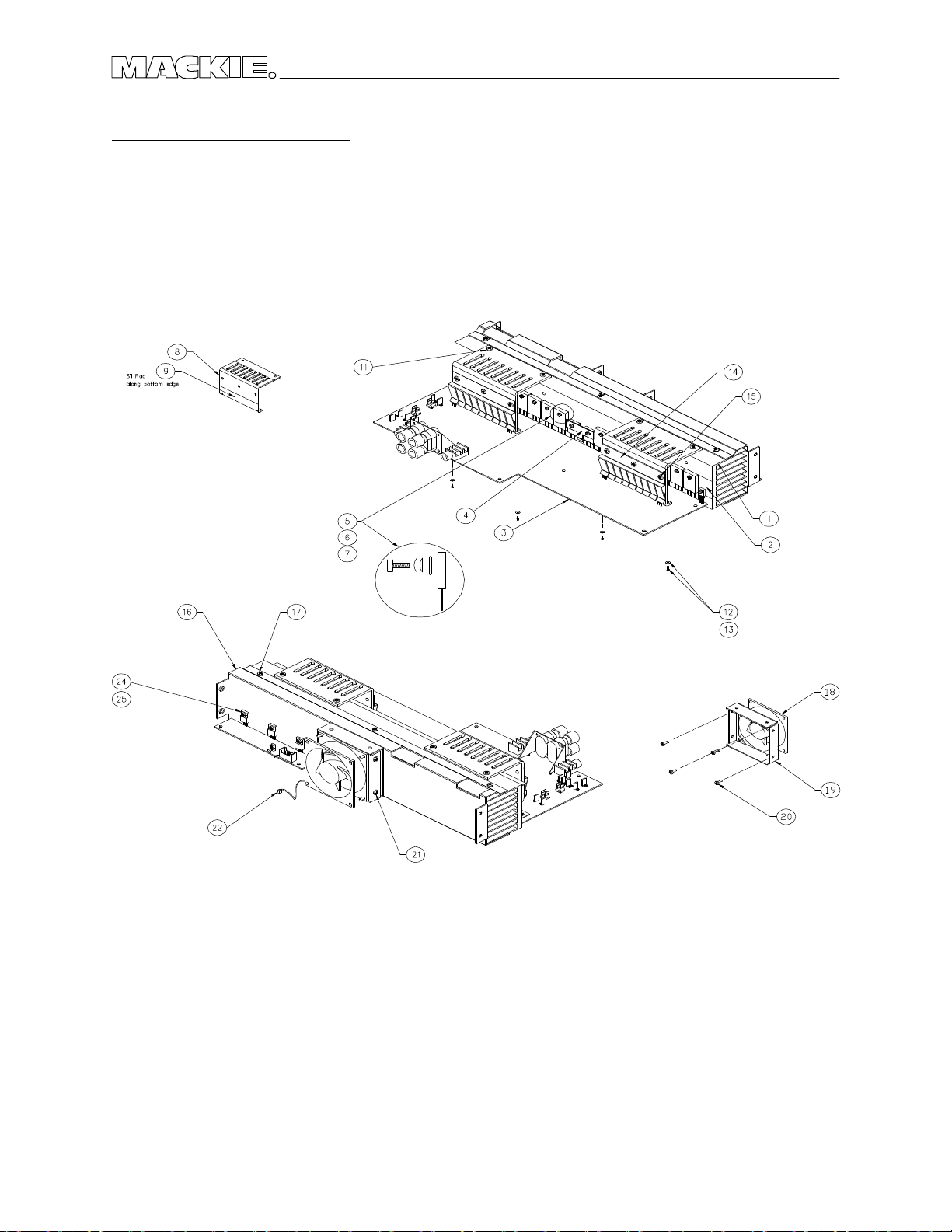
HEATSINK ASSEMBLY
M•1200/M•1400 SERVIC E MANUAL
18
PARTS
Page 21

VERSIO N 1.1
HEATSINK ASSEMBLY PARTS LIST
ITEM # PART # DESC RIPTIO N
1 551-032-00 EXTR FAB HEA TSINK - M1200
2 410-003-00 INSL SILPAD K6 W/ ADHESIVE
3 055-081-00 PC B ASSY MAIN - 1200
3 080-072-01 PC B ASSY MAIN - M1400
3 080-072-02 PC B ASSY MAIN - M1400i
4 550-255-00 PIGGYBAC K C LIP
5 700-058-02 MCH 4-40X1/ 2 SKT C LRZC
6 710-020-00 WASH NO .4 C OMPRESSIO N
7 710-022-00 WASH FLAT NO .4 FENDER
8 550-224-00 BRAC KET SUBSINK - M1200
9 410-003-00 INSL SILPAD K6 W/ ADHESIVE
11 700-010-00 TF 6-32X1/ 4 PHP BLKZC
12 710-013-00 WASH FLAT NO.6 FIBRE
13 700-010-04 TF 6-32X3/ 8 PHP BLKZC
14 550-237-00 SPRING C LIP SUBSINK-M1200
15 700-028-02 SEMS 6-32X3/ 8 PHP BLKZC
16 550-225-00 HEA TSINK C OWLING - M1200
17 700-010-00 TF 6-32X1/ 4 PHP BLKZC
18 770-006-00 FAN 80MM 24VDC -MEC HATRO NI
18 770-007-00 FAN 80MM 24VDC -PANASONIC
19 550-219-00 BRKT FAN PS - SR40.8
20 700-047-04 MCH 10-32X3/ 8 FIL PHL CLR
21 700-028-02 SEMS 6-32X3/ 8 PHP BLKZC
22 400-083-00 2P .100X1 22G A END
24 700-058-02 MCH 4-40X1/ 2 SKT C LRZC
25 710-020-00 WASH NO .4 COMPRESSIO N
PARTS
19
Page 22

C O MPLETE PARTS LIST
040- Ca b les
055- Finishe d PC B Assys
100- Po ts a nd Re sisto rs
200- Ca p a c ito rs
300- Se m ic o nd uc tors
400- Jac ks/Co nne c to rs
500- Switc he s
510- Fuses
550- Cha ssis Me tal
600- Tra nsfo rm e rs
601- Induc to rs
610- Wire s a nd Ca b les
M•1200/M•1400 SERVIC E MANUAL
640- AC Line Co rd s
700- Ha rd w a re
760- Kno b s/ Pla stic
790- Misc ./ Pac king
800- Printe d Ma teria l
PART # DESC RIPTION
040-033-02 RIB 28G A TRANS 20C 18IN
040-033-03 RIB 28G A TRANS 20C 4IN
040-117-02 RIB 28G TRNS 10C .10 11.5
055-079-00 PCB ASSY INPUT 1200/ 1400
055-080-00 PCB ASSY DISPLY 1200/ 1400
055-081-00 PCB ASSY MAIN - 1200
080-072-01 PCB ASSY MAIN - M1400
080-072-02 PCB ASSY MAIN - M1400i
080-034-00 PCB ASSY SO FT START – 120V
080-034-01 PCB ASSY SO FT START – 240V
080-023-10 PNT HANDLE ASSY RIG HT
080-023-20 PNT HANDLE ASSY LEFT
080-035-00 PWR SW HARNESS - AMP
100-001-00 RES C F .125W 5% 10 O HM
100-017-00 RES C F .125W 5% 47 O HM
100-023-00 RES C F .125W 5% 82 O HM
100-027-00 RES C F .125W 5% 120 O HM
100-030-00 RES C F .125W 5% 160 O HM
100-031-00 RES C F .125W 5% 180 O HM
100-035-00 RES C F .125W 5% 300 O HM
100-040-00 RES C F .125W 5% 430 O HM
100-042-00 RES C F .125W 5% 510 O HM
100-045-00 RES C F .125W 5% 680 O HM
100-049-00 RES C F .125W 5% 1K OHM
100-050-00 RES C F .125W 5% 1K1 OHM
100-056-00 RES C F .125W 5% 2K OHM
100-061-00 RES C F .125W 5% 3K3 OHM
100-068-00 RES C F .125W 5% 6K2 OHM
100-071-00 RES C F .125W 5% 8K2 OHM
100-072-00 RES C F .125W 5% 9K1 OHM
100-073-00 RES C F .125W 5% 10K O HM
100-075-00 RES C F .125W 5% 12K O HM
100-076-00 RES C F .125W 5% 13K O HM
100-080-00 RES C F .125W 5% 20K O HM
100-082-00 RES C F .125W 5% 24K O HM
100-083-00 RES C F .125W 5% 27K O HM
100-084-00 RES C F .125W 5% 30K O HM
100-086-00 RES C F .125W 5% 36K O HM
100-089-00 RES C F .125W 5% 47K O HM
100-092-00 RES C F .125W 5% 62K O HM
100-093-00 RES C F .125W 5% 68K O HM
PART # DESC RIPTION
100-094-00 RES C F .125W 5% 75K O HM
100-097-00 RES C F .125W 5% 100K OHM
100-109-00 RES C F .125W 5% 1M O HM
100-110-00 RES C F .125W 5% 360K OHM
100-111-00 RES C F .125W 5% 390K OHM
105-277-00 RES MF .125W 1% 750 O HM
105-331-00 RES MF .125W 1% 2K49 O HM
110-036-00 RES C F .25W 5% 300 O HM
110-046-00 RES C F .25W 5% 750 O HM
115-427-00 RES MF .25W 1% 24K9 O HM
121-097-00 RES MO 1W 5% 10K O HM
123-009-00 RES MO 3W 5% .22 O HM
123-033-00 RES MO 3W 5% 2.2 O HM
123-056-00 RES MO 3W 5% 20 OHM
123-071-00 RES MO 3W 5% 82 OHM
123-085-00 RES MO 3W 5% 330 O HM
123-109-00 RES MO 3W 5% 3.3K O HM
123-124-00 RES MO 3W 5% 13K O HM
125-020-00 RES WW 15W 5% 82 O HM CMNT
130-017-02 POT RTY 50KC 12MM DUAL TN
130-036-00 POT RTY 5KA 16MM DL DTNT
130-037-02 POT RTY 10KC 9MM TN
130-038-00 POT TRIM 500B HO RIZ
140-025-00 RES TF SM .1W 5% 10 O HM
140-057-00 RES TF SM .1W 5% 220 O HM
140-060-00 RES TF SM .1W 5% 300 O HM
140-065-00 RES TF SM .1W 5% 470 O HM
140-068-00 RES TF SM .1W 5% 620 O HM
140-073-00 RES TF SM .1W 5% 1K0 O HM
140-076-00 RES TF SM .1W 5% 1K3 O HM
140-078-00 RES TF SM .1W 5% 1K6 O HM
140-080-00 RES TF SM .1W 5% 2K0 O HM
140-081-00 RES TF SM .1W 5% 2K2 O HM
140-083-00 RES TF SM .1W 5% 2K7 O HM
140-087-00 RES TF SM .1W 5% 3K9 O HM
140-089-00 RES TF SM .1W 5% 4K7 O HM
140-092-00 RES TF SM .1W 5% 6K2 O HM
140-094-00 RES TF SM .1W 5% 7K5 O HM
140-097-00 RES TF SM .1W 5% 10K O HM
140-106-00 RES TF SM .1W 5% 24K O HM
140-108-00 RES TF SM .1W 5% 27K O HM
20
PARTS
Page 23

VERSIO N 1.1
PART # DESC RIPTION
140-111-00 RES TF SM .1W 5% 36K O HM
140-115-00 RES TF SM .1W 5% 51K O HM
140-123-00 RES TF SM .1W 5% 100K O HM
140-124-00 RES TF SM .1W 5% 120K O HM
140-139-00 RES TF SM .1W 5% 470K O HM
140-147-00 RES TF SM .1W 5% 1M O HM
145-318-00 RES MF SM .1W 1% 2K00 O HM
145-389-00 RES MF SM .1W 1% 10K0 O HM
145-397-00 RES MF SM .1W 1% 12K1 O HM
145-406-00 RES MF SM .1W 1% 15K0 O HM
145-469-00 RES MF SM .1W 1% 68K1 O HM
145-478-00 RES MF SM .1W 1% 84K5 O HM
145-485-00 RES MF SM .1W 1% 100K O HM
145-547-00 RES MF SM .1W 1% 442K O HM
150-009-00 RES FUS .25W 5% 2.2 O HM
150-037-00 RES FUS .25W 5% 33 OHM
150-045-00 RES FUS .25W 5% 68 OHM
200-001-02 PLY .012UF 10% 100V TR
200-004-02 PLY .047UF 10% 100V TR
200-007-02 PLY .01UF 10% 100V TR
200-015-02 PLY .0047UF 10% 100V PEI
200-022-02 PLY .47UF 5% 50V TR
200-023-00 PLY/ BX .001UF 20% 250V Y2
200-024-00 PLY/ BX .01UF 20% 250V Y2
200-025-02 PLY/ BX .56UF 5% 63V TR
200-036-00 PLY/ BX .1UF 10% 250V
205-002-02 MICA 270PF 5% 500V TR
210-001-02 C ER .01UF +80/ -20% 50V TR
210-010-02 C ER 47PF 5% 500V NPO TR
210-017-02 C ER 470PF 5% 500V Y5E TR
211-003-00 C ER .001UF 10% 50V AX
211-009-00 C ER .1UF 20% 50V AX
212-001-00 C ER .01UF 10% 50V X7R SM
212-004-00 C ER 220PF 5% 50V NPO SM
212-009-00 C ER 47PF 5% 50V NPO SM
212-010-00 C ER .1 +80/ -20 25V Z5U SM
220-001-02 LYT 22UF 20% 25V RAD TR
220-002-02 LYT 47UF 20% 25V RAD TR
220-004-02 LYT 470UF 20% 6.3V RAD TR
220-007-00 LYT 100UF 20% 100V RAD
220-011-02 LYT 100UF 20% 25V RAD
220-014-00 LYT 2.2UF 20% 50V RAD
220-025-00 LYT 1000UF 20% 35V RAD
220-027-02 LYT 10UF 20% 50V RAD TR
220-033-00 LYT 10000UF 20% 80V RAD
220-034-00 LYT .47UF 20% 100V RAD
220-035-00 LYT 12000UF 20% 80V RAD
220-039-00 LYT 1000 20 25V RAD SMDIA
220-040-00 LYT 10UF 20% 160V RAD
300-001-00 DIO SIG 1N4148 100V 500MW
PART # DESC RIPTION
300-003-00 DIO SW DL4148 100V SM
300-007-00 DIO SW 1SS244-SUB 1SS245
301-006-00 THY 2N6507 400V
301-007-00 DIO PWR DUAL FEP30 (D7)
301-008-00 DIO PWR DUAL FEN30 (D8)
301-009-00 DIO PWR 1N4004
301-010-00 DIO PWR 1N5404 3A 400V
301-014-00 DIO PWR 1N4007
302-001-00 DIO ZEN 1N5261B 47V 500MW
302-003-00 DIO ZEN 1N4745A 16V 1W
304-001-00 LED RED T-1
304-004-00 LED GREEN T-1
310-002-00 XSTR PNP 2N4403
310-007-00 XSTR NPN 2N4401
310-023-02 XSTR NPN 2SC2362K TR
310-028-00 XSTR PNP 2SB940A POWER
310-029-00 XSTR NPN 2SD1264A PO WER
310-032-02 XSTR PNP 2SA1016K TR
310-033-00 XSTR PNP MJL21193
310-034-00 XSTR NPN MJL21194
310-035-00 XSTR PNP 2SA1478
310-036-00 XSTR NPN 2SC3788
310-037-00 XSTR NPN MJE340 POWER
310-038-00 XSTR PNP MJE350
310-042-00 XSTR NPN MJE15032
310-043-00 XSTR PNP MJE15033
311-002-00 XSTR PNP MMST4403 SM
320-004-00 O PAMP 4560F
323-001-00 LM339 Q UAD C O MP
323-002-00 LM339D Q UAD C O MP SM
329-012-00 VTL5C 10 OPTOCOUPLER
329-014-00 LM35DZ PREC TEMP SENSO R
400-059-00 TERM QDISC .250 MALE PC MT
400-060-00 FUSE CLIP PCMT 5MM DIA
400-061-00 HDR 2P .100X1 STR LO CK
400-065-00 TERM QDISC .250 F 18-22G A
400-077-00 HDR 20P .1X2 STR LC K SHRD
400-078-00 HDR 10P .1X2 STR LC K SHRD
400-083-00 2P .100X1 22G A END
400-118-00 JAC K 1/ 4 HORIZ PCMNT MO NO
400-119-00 TERM BANANA Q UA D HRZ PCMT
400-129-00 FUSE CLIP .25 DIA PC MNT
400-133-00 HDR 6CK 11A/ 600V
400-134-00 REC P 6C K 11A/ 600V
400-135-00 TERM 11A/ 600V F 18-20G A
400-138-00 SPEA KONS HORIZ 4 C KT
400-141-00 XLR 3P F VERT A-SERIES
400-142-00 XLR 3P M VERT A-SERIES
400-143-00 HDR 3P .100X1 STR
400-171-00 HDR 2P .100X1 STR
PARTS
21
Page 24

M•1200/M•1400 SERVIC E MANUAL
PART # DESC RIPTION
400-172-00 TERM SOLDER-IN 18A WG
400-173-00 TERM .25 Q KDS PC MT STABLE
400-210-00 TERM QDISC .250 F 18-22G A
400-214-00 JAC K 1/ 4 V PCMNT 1MM WASH
410-003-00 INSL SILPAD K6 W/ ADHESIVE
500-022-00 SW RCKR ILLUMINATED
500-023-00 SW SLIDE 4P3T MINI
500-024-00 SW SLIDE DPDT MINI
501-002-00 RELA Y SPDT 30AMP 110VDC
510-017-00 FUSE SB 20A 3AB 1/ 4X1-1/ 4
510-021-00 FUSE FB 10A 5X20MM 250V
550-219-00 BRKT FAN PS - SR40.8
550-221-00 TO P C O VER - M1200
550-222-00 BTM C OVER - M1200
550-223-10 SIDE RAIL RIGHT - M1200
550-223-20 SIDE RAIL LEFT - M1200
550-224-00 BRACKET SUBSINK - M1200
550-225-00 HEATSINK C O WLING - M1200
550-237-00 SPRING C LIP SUBSINK-M1200
550-244-00 BO TTO M COVER - M1400
550-247-00 SHIELD INPUT - M1200
550-249-00 PLATE XFMR MTG - M1200
550-255-00 PIG G YBAC K C LIP
550-275-00 SPAC ER PLA TE - AMPLIFIER
550-277-00 SC REEN MANIFO LD - M1400
551-029-00 EXTR SC RN DSPLY BZL-M1200
551-029-10 EXTR SC RN DSPLY BZL-M1400
551-032-00 EXTR FAB HEATSINK - M1200
553-002-01 C RS 18G A 36 X 120
553-002-03 C RS 18G A 48 X 120
553-006-03 EG 18G A 48 X 120
553-007-03 AL .063 48 X 120
553-010-03 EG 20G A 48 X 120
553-015-03 AL .125 1100 H14 48 X 120
553-017-01 SS .048 17-7 36 X 120
600-016-00 XFMR M1200 120V
601-006-00 INDUCTOR AIR COIL 1UH
611-029-02 WIR 18GA 1007 BLK 5IN ST2
611-038-00 WR 18G 1010 G N/ YL 4IN ST2
660-005-00 22G A JUMPER WIRE
700-005-00 SEMS 8-32X1/ 2 PHP BLKZC
700-010-00 TF 6-32X1/ 4 PHP BLKZC
700-010-04 TF 6-32X3/ 8 PHP BLKZC
700-011-00 MC H 4-40X1/ 4 BTNSKT BLKO X
700-028-02 SEMS 6-32X3/ 8 PHP BLKZC
700-028-04 SEMS 6-32X3/ 4 PHP BLKZC
700-041-04 MC H 6-32X3/ 8 FL 100DG BLK
700-047-04 MC H 10-32X3/ 8 FIL PHL C LR
700-050-04 MC H 6-32X3/ 8 FIL PHL C LR
700-055-00 MC H 4-24X3/ 8 PHP BLK HILO
PART # DESC RIPTION
700-058-02 MC H 4-40X1/ 2 SKT CLRZC
700-059-00 HEX 5/ 16-18X3IN G D-5
704-001-01 PEMNUT 6-32 .038 STL
704-001-02 PEMNUT 6-32 .054 STL
704-007-01 PEMNUT 4-40X.060L SS FLSH
704-023-03 STUD 6-32X.500 STL FLSH
705-001-00 KEPNUT 6-32
705-003-00 NUT (SPLD W/ JAC K)
705-013-00 NUT HEX M7 BLK
705-015-00 NUT SLOT NC KL SPLD W/ JAC K
705-018-00 NUT HEX 5/ 16-18 (G D-5)
706-036-01 6-32X.188L STL PEM
706-036-03 STDF 6-32X.312L STL PEM
706-045-00 SPCR PVC .770 LED HI TEMP
710-002-00 WASHER (SPLD WITH JAC K)
710-013-00 WASH FLAT NO.6 FIBRE
710-017-00 WASH SPLTLC K 5/ 16 HEAVY
710-019-00 WASH FIBRE BLK (W/ JAC K)
710-020-00 WASH NO.4 C O MPRESSIO N
710-022-00 WASH FLAT NO.4 FENDER
710-023-00 WASH STAR M7 .020 THK
710-024-00 WASH FLAT 5/ 16 HARD (USS)
711-001-00 LUG NO.6 SO LDER STAR
712-020-00 BRKT A NG 6-32X.037THK STL
712-021-01 RVT CL END .125X.062-.125
740-004-00 STRAIN RELIEF HEYCO 1244
760-048-04 KNOB 9MM DARK G RAY
760-061-00 KNOB VOLUME M1200
770-006-00 FAN 80MM 24VDC -MEC HATRONI
770-007-00 FAN 80MM 24VDC -PANASONIC
780-042-00 INSUL MYLAR INPUT SHIELD
780-114-00 RUBBER WASHER - THIN
790-002-00 BAG PO LY 12 X 18 2MIL
790-016-00 BAG PO LY 24X30 4MIL-M1200
800-066-00 BO X M1200
800-069-00 BO X M1400
810-056-00 INST TO P/ BOTTO M - A MP
820-062-00 O WN MNL - M1200/ M1400
820-062-10 O WN MNL – M1400i
830-016-00 REG & WARR CA RD FR SERIES
22
PARTS
Page 25
TH E M IX ER FI XER • MACK IE DESIGN S SERV ICETH E M IX ER FI XER • MACK IE DESIGN S SERV ICE
F1=20A
NEWSNEWS
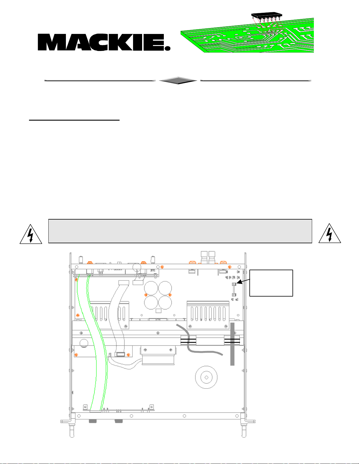
FR Se rie s Fuse Upg ra d e
Mo d e l: FR Se rie s M1200/ 1400, 110V o nly
Se rial # : M1200 p rio r to SN# AF12626 Effe c tive 4/ 28/ 97
M1400 p rio r to SN# AH12657
Pro b le m : O rig ina l fuse (15A) ra te d to o lo w . Turn o n inrush c urre nt c ause s fuse to
o p e n.
So lutio n: Re p la c e the ma in (F1) fuse w ith a 20A 250V slo w b lo w fuse .
Attentio n!: Sinc e yo u will b e w o rking d ire c tly with the AC p o we r line , g re at c a re sho uld b e
take n in all a sp e c ts o f the installatio n. Po w e r sho uld b e d isc o nne c te d fro m the unit p rio r
to the insta lla tio n p ro c e ss.
250V
Slow Blow
Top
View
FR Se rie s Fuse up g rad e BC 6/ 20/ 97
Page 26
TH E M IX ER FI XER • MACK IE DESIGN S SERV ICETH E M IX ER FI XER • MACK IE DESIGN S SERV ICE
NEWSNEWS
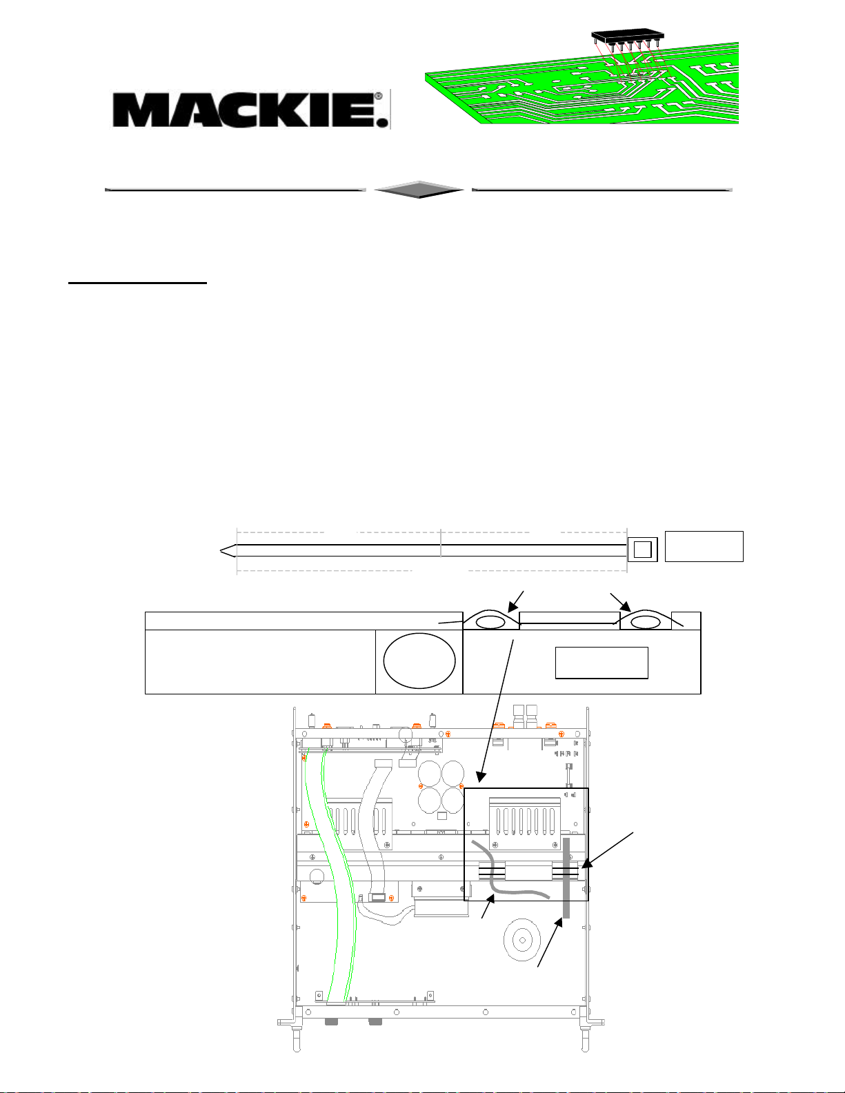
FR Tywra p Mod
Mo d e l: FR Se rie s M1200/ 1400
Se rial # : AFXXXXX to AFXXXXX Effe c tive 5/ 8/ 97
Pro b le m : The p rim a ry a nd se c o nd a ry w ire s g e t p inc he d b e twe e n the to p c o ve r a nd
the fa n shro ud.
So lutio n: Install a 7 ½” tyw ra p thro ug h the fa n shro ud tunne ls. (740-016-00 15 1/ 16”
tywra p, c ut to 7 ½” )
Top
View
7 ½”
15 1/ 16”
Fa n
Transformer secondary
wires
7 ½”
Tywra p
7 ½” tywa rp
Fro nt Vie w
To p Vie w
Transformer primary
wires
FR Tyw ra p Mo d BC 4/ 28/ 97
Page 27
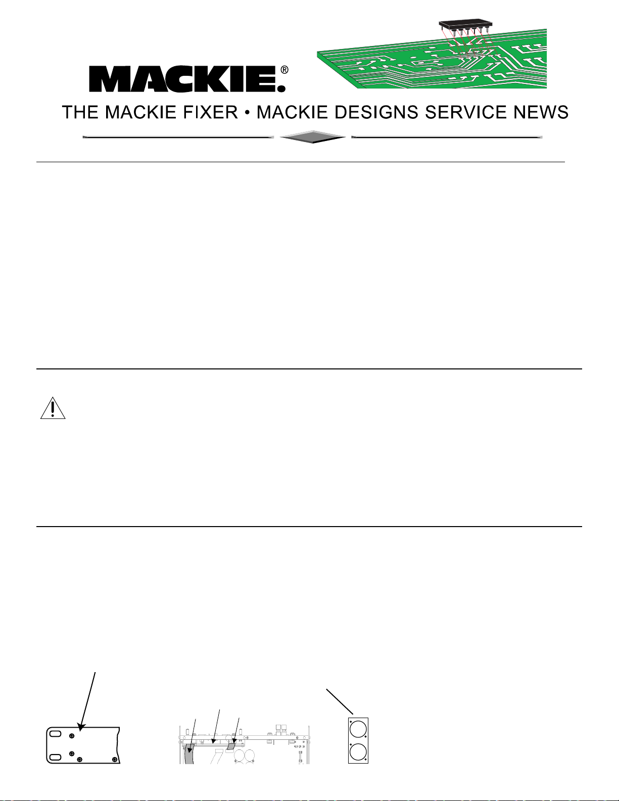
FR series Amplifier ribbon replacement instructions (NEW! IMPROVED! July 2000)*
Models affected: FR series M1200, M1400, M1400i
M1200: All models. M1400i: Before Serial # DA20889 and all models with “AM” prefix.
M1400 and 230v versions: Before Serial # DB12700 and all models with “AH” prefix.
Add this as part of your normal repair procedures.
Note: This bulletin replaces all previous ribbon bulletins.
Symptom:
Ch.1 or 2 output signal intermittently fades out, or cuts out completely and/or the DC supply rail fuses blow.
Possible Cause:
The two ribbon cables from the input board may be defective
Solution:
*Replace the input ribbon cables with an improved type in all of the above models, (including any which
have had the previous ribbon bulletin completed).
Safety Warning:
Caution! These instructions are for use by qualified personnel only. To avoid electric shock, do not
perform any servicing unless you are qualified to do so. Refer all service to qualified personnel.
Tools Required:
Phillips screwdriver, Torx and Allen drivers, needle nose pliers, safety glasses.
Parts Required:
040-359-00 Ribbon cable, 28GA, 20 Pin, Length 4.25”, PLZD Quantity = 1
040-360-00 Ribbon cable, 28GA, 20 Pin, Length 18”, PLZD Quantity = 1
400-077-00 20 Pin Headers Quantity = 2
Procedure:
1. Remove all cords (including the power cable and speaker outputs) from the amplifier.
2. Take off the top cover and inspect the ribbon cables. If they are not marked 040-359-00 or
040-360-00 then proceed as follows:
Remove the input board:
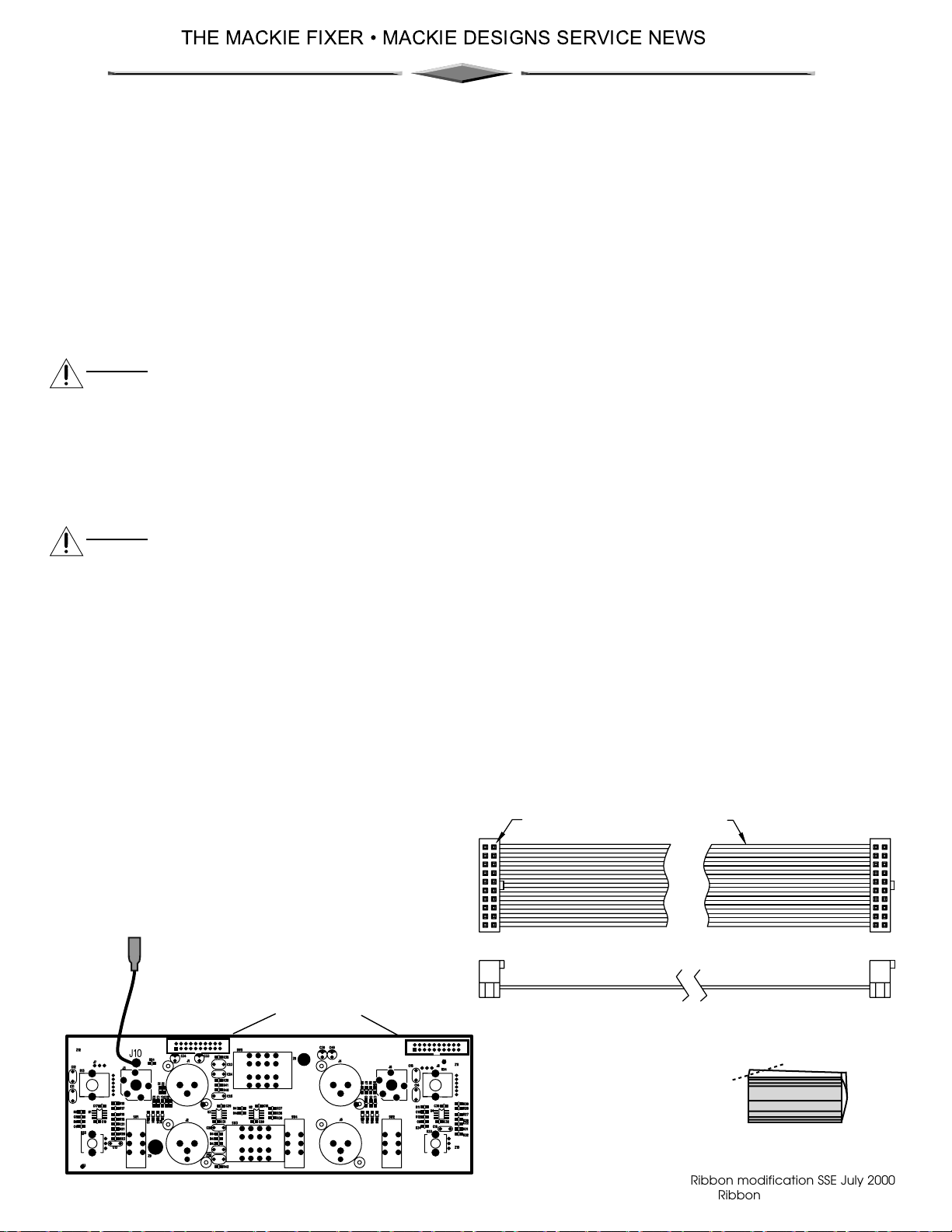
3. Undo the XLR screws, TRS nuts, and pull out the four pot knobs.
4. Disconnect the short ribbon cable from the amp board, and the long cable from the front panel
display board. On later amplifiers, you will have to remove the front display board first.
5. Disconnect the black ground wire from the amp board.
6. Undo the four screws on the right side of the chassis. This will give enough room to pull out the input
board. Catch the two metal XLR plates before they fall inside (not present on later amplifiers).
Input
board
Ribbon
Ribbon
XLR plates
Continued....
Ribbon modification SSE July 2000
Ribbon mod.pdf, page 1 of 2
Page 28
THE MACKIE FIXER MACKIE DESIGNS SERVICE NEWS
Procedure continued.
Input board work:
If the two ribbon cables are soldered to the input board, follow steps 7 to 11. If not, then go to step 12.
7. Remove the metal shield plate and insulator sheet from the back of the input board.
8. Carefully unsolder the ribbon cable headers from J16 and J11.
Discard part# 040-033-03, 4 inch ribbon cable.
Discard part# 040-033-02, 18 inch ribbon cable.
9. Solder two new headers (#400-077-00) to the input board, with the cutout side pointing towards
the center of the input board (i.e. downwards).
10. Replace the metal shield plate and insulator sheet onto the back of the input board.
11. Add part# 040-359-00, 4.25 inch ribbon cable to J11.
Add part# 040-360-00, 18 inch ribbon cable to J16.
Align each cable’s color stripe with the header’s pin 1.
Make sure both ribbons are fully inserted, then proceed to step 15.
If the two ribbon cables are not soldered to the board, follow steps 12 to 14.
12. Discard part# 040-062-00, 4.25 inch ribbon cable.
Discard part# 040-062-02, 18 inch ribbon cable. You may have to undo the display board screws
in order to remove it from J1.
13. Add part# 040-359-00, 4.25 inch ribbon cable to J11.
Add part# 040-360-00, 18 inch ribbon cable to J16.
Align each cable’s color stripe with the header’s pin 1.
Make sure both ribbons are fully inserted.
14. Refit the display board, once the long ribbon cable is securely attached to J1.
Putting the input board back in:
15. Add the two metal XLR plates (where fitted) and carefully fit the input board back in place. Put
the four pot knobs back after the board is in place.
16. It can be difficult getting the knobs back on through the chassis holes, but you can make it easier
by snipping off a bit of the plastic center ridge, as shown in the little knob diagram below.
17. Add and tighten all the nuts and screws, and the four chassis screws (removed in step 6).
18. Make sure that all ribbon cables are secure and that all ends are fully inserted.
19. Reconnect the black wire from the input board to the amp board.
20. Replace the top cover.
21/ Perform a complete specification and safety test before returning the unit to the customer.
Input
board
J11
Headers
Pin 1 Color Stripe
J16
snip off
knob
Ribbon modification SSE July 2000
Ribbon mod.pdf, page 2 of 2
Page 29
M•1200/ M•1400 INPUT PC B 055-079-00 REV-D
23
Page 30
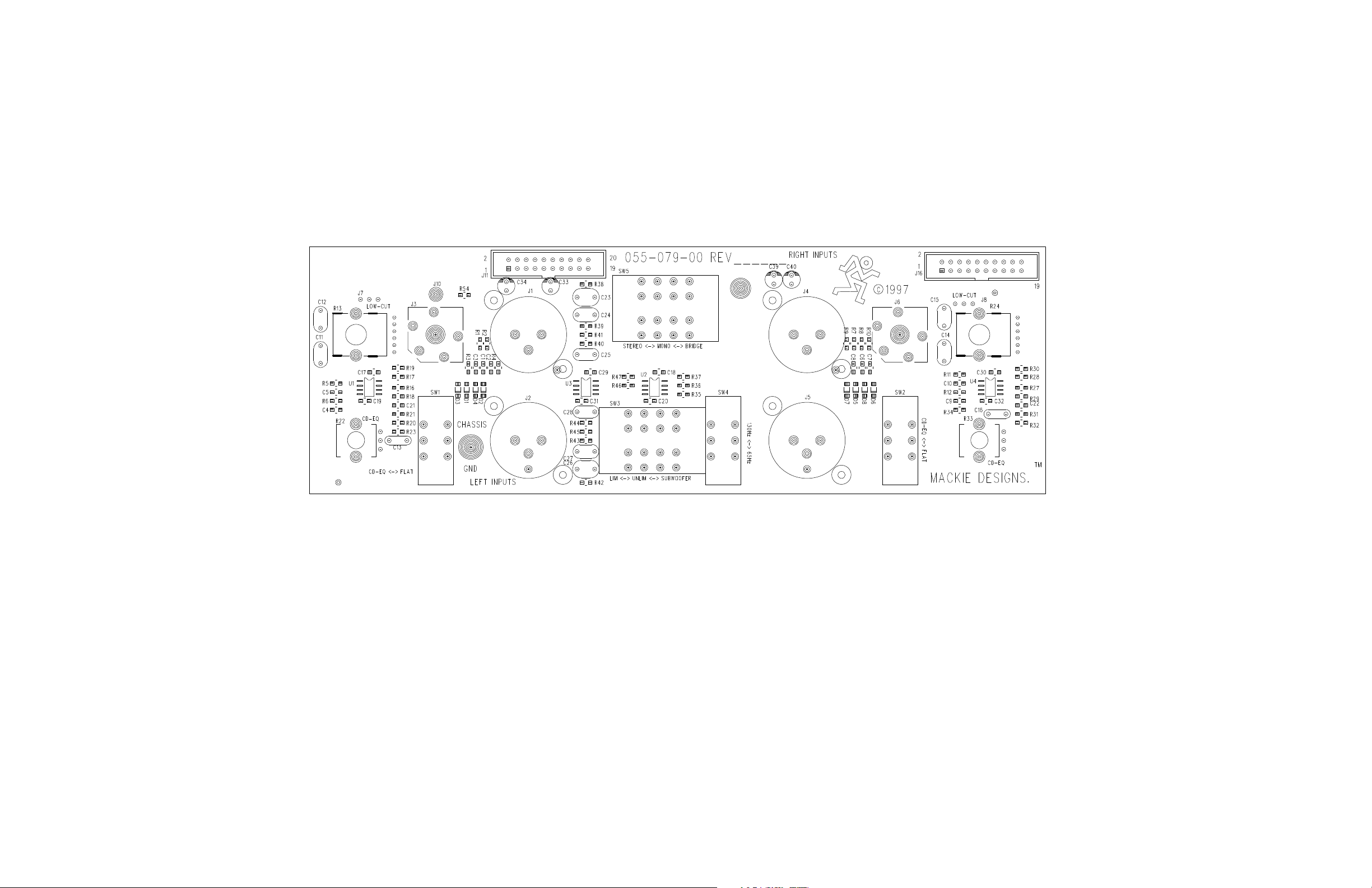
M•1200/ M•1400 INPUT PC B 055-079-00 REV-D
24
Page 31
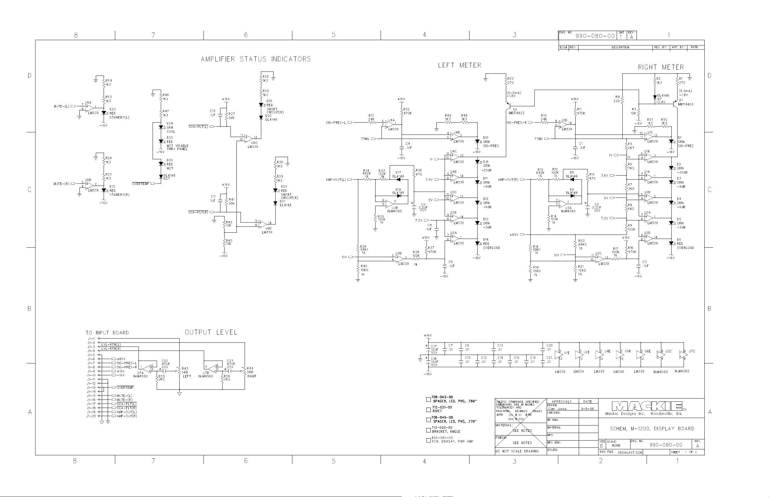
M•1200/ M•1400 DISPLAY PCB 055-080-00 REV-A
25
Page 32
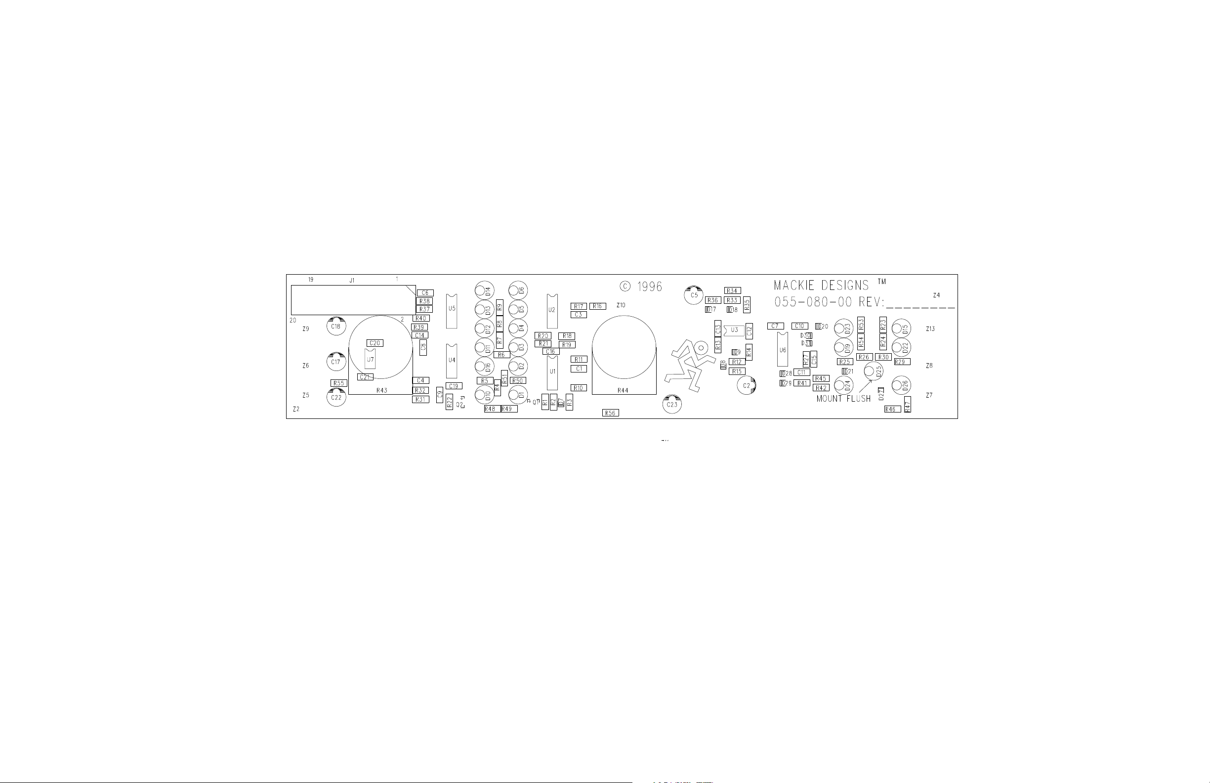
M•1200/ M•1400 DISPLAY PCB 055-080-00 REV-A
26
Page 33
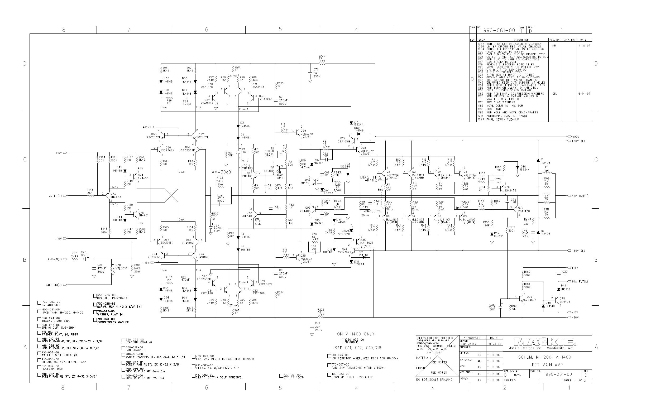
M•1200/ M•1400 MAIN PC B 055-081-00 REV-D
27
Page 34
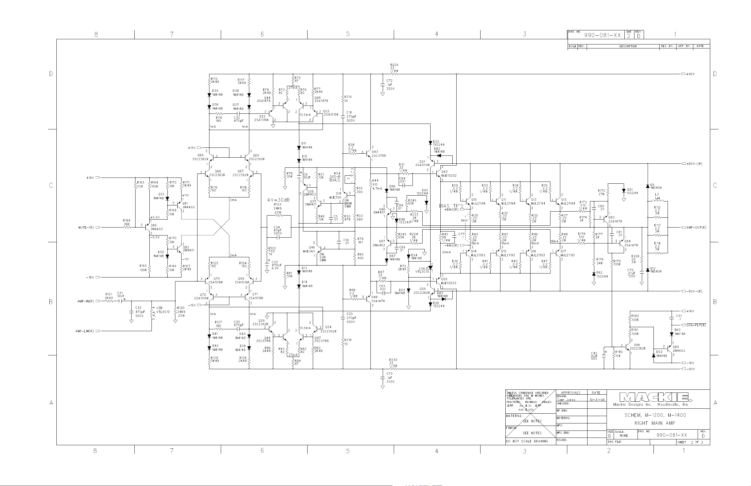
M•1200/ M•1400 MAIN PC B 055-081-00 REV-D
28
Page 35
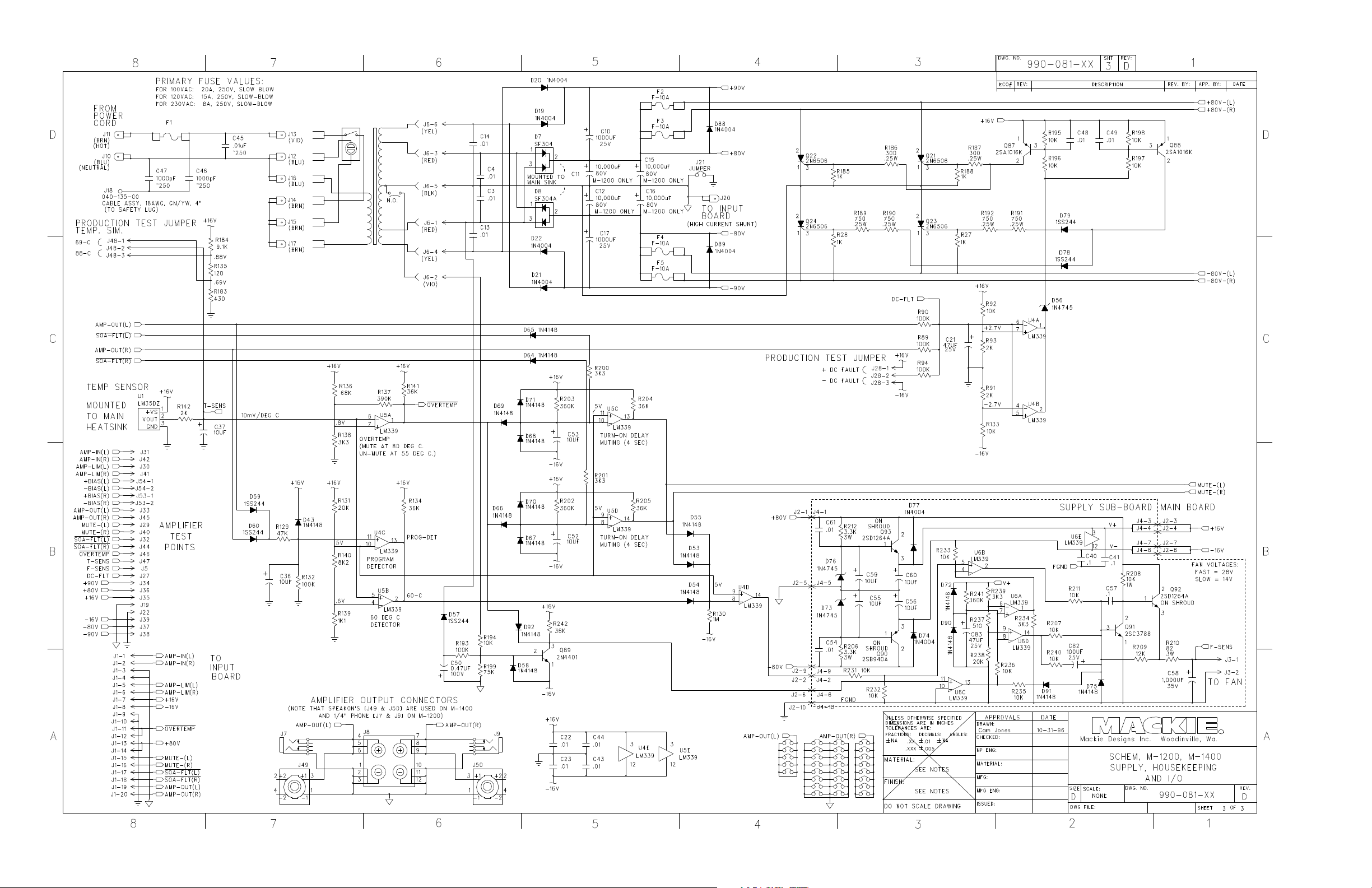
M•1200/ M•1400 MAIN PC B 055-081-00 REV-D
29
Page 36
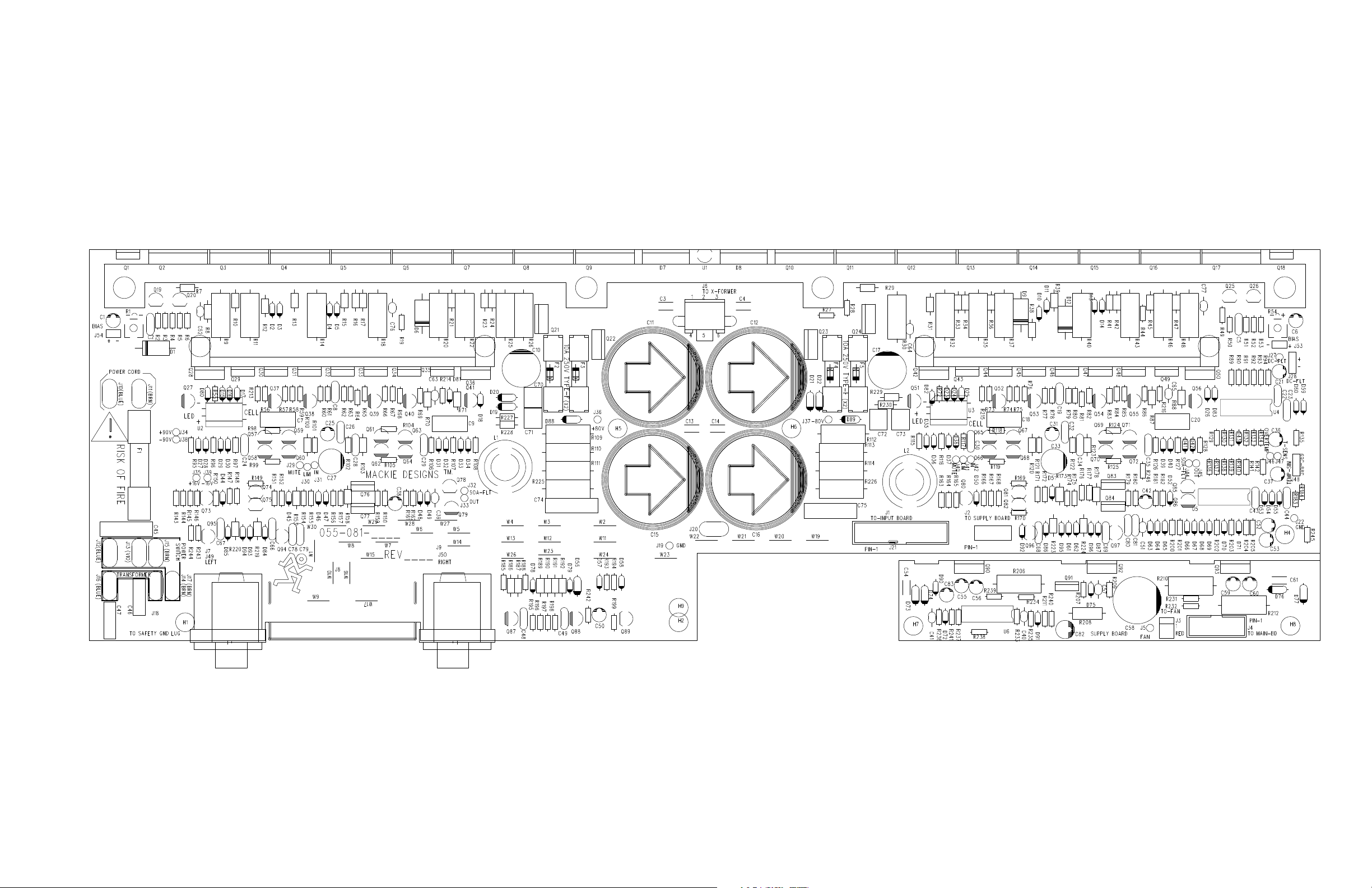
M•1200/ M•1400 MAIN PC B 055-081-00 REV-D
30
Page 37
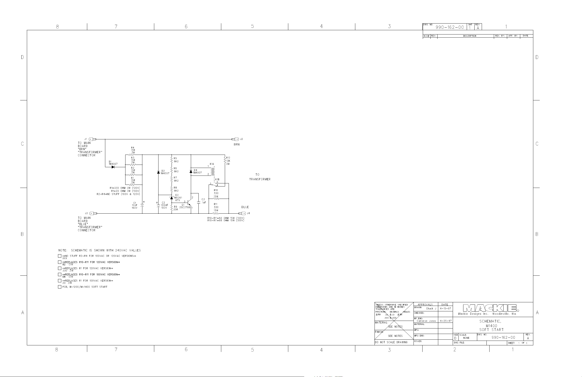
M•1200/ M•1400 SO FT START PCB 055-162-00 REV-A
31
Page 38
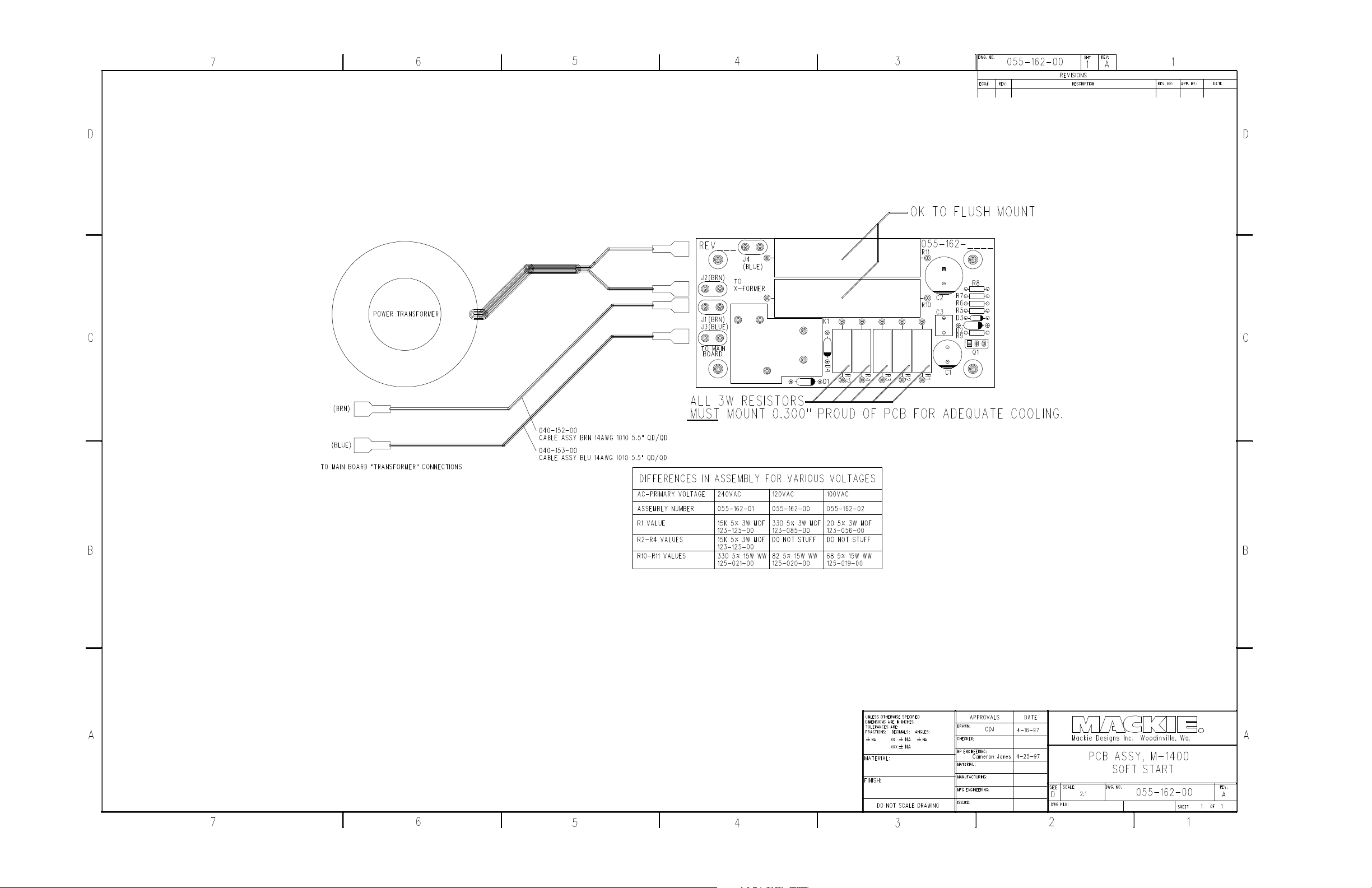
M•1200/ M•1400 SO FT START PCB 055-162-00 REV-A
32
Page 39
M•1400 / M•1400i / M•1200
SERVICE MANUAL
Version 1.2
1998 MACKIE DESIGNS, INC.
820-179-00
Page 40
CAUTION AVIS
CAUTION
AVIS
RISK OF ELECTRIC SHOCK
DO NOT OPEN
RISQUE DE CHOC ELEC TRIQUE
NE PAS OUVRIR
CAUTION: TO REDUCE THE RISK OF
ELECTRIC SHOCK DO NOT REMO VE
THE COVER
NO USER SE RVIC EABLE PARTS INSIDE
REFER SERVICING TO QUALIFIED
PERSONN EL
WARNING: TO REDUCE THE RISK OF
FIRE OR ELECTRIC SHOCK, DO N OT
EXPOSE THIS PRODUCT TO RAIN OR
MOISTURE
TO PREVENT ELECTRIC SHOCK, DO
NOT USE THIS POLARIZED PLUG WITH
AN EXTENSION CORD, RECEPTAC LE OR
OTHER OUTLET UNLESS THE BLADES
CAN BE FULLY INSER TED TO PREVENT
BLADE EXPOSURE.
The lig htning flash w ith arro wh ea d symb o l within a n
e quilate ral trian gle is inte nde d to ale rt the use r to the
p re se nc e o f uninsula te d "d ang ero us v olta ge " w ithin the
p ro d uc t's e nc lo sure, tha t ma y b e o f suffic ient m ag nitud e to
c on stitud e a risk o f ele ctric sho c k to pe rson s.
Le symb o le é c la ir av e c p o int de fléc he à l'inte rie ur d 'un
tria ng le é q uila té ra l e st utilisé p our a le rte r l'utilisa te ur d e la
p ré se nce à l'inte rieur d u c of fre t d e "vlo tag e d ang e re ux" no n
iso le d 'a mp le ur suffisa nte p o ur c on stitue r un risq ue
d 'é lé c tro c ution.
AT TENT ION : POUR EVITE R LE S
RI SQUES DE CHOC ELECT R IQU E, NE
PA S EN LEV ER L E COUV ERCLE . A U CUN
EN TRET IEN DE PIECE S IN TER IEUR ES
PAR L'US AGE R. C ONFIER L 'ENT RET IEN
AU PER SON NEL QUALIF IE .
AV IS:POUR EV ITER LE S R ISQUES
D'I NCE NDI E OU D'ELECT R OCU TION,
N'EXP OSEZ PAS CET ARTIC LE A LA
PLUIE O U A L'H UMIDITE.
POUR PREVE NIR LES CHOC S
ELECT RIQUES NE PAS UTIL ISE R CE TTE
FICHE PO LA RI SEE AVEC UN
PR OLON GAT EUR, UN PRISE D E
COURA N T O U UNE AUTRE S ORT IE DE
COURA NT, SAUF SI LES LA MES
PE UVEN T E TRE INSEREE S A FOND
SA N S L AIS SER AUC UNE PA R T IE A
DE C OUVER T .
The exc lam ation p o int within a n e q uila te ra l tria ng le
is intend e d to a le rt the use r to the p re se nc e of
imp o rta nt op e ra ting and ma inte nan c e ( se rvicing )
instruc tio ns in the literature a c c om pa nying the
a pp lia nce .
Le p o int d'e xc la ma tio n à l'inté rie ur d 'u n tria ng le d e
la pré se nc e d 'instruc tio ns imp orta nte s p ou r le
fo nc tio nne me nt e t l'e ntre tien (se rvic e ) da ns le livre t
d 'in struc ion a c c o mp a g na nt L'a p p a re il.
Page 41
®
TABLE O F C O NTENTS
INTRO DUC TION............................................................. 2
SYSTEM O VERVIEW ....................................................... 3
SUMMARY O F FEATURES .....................................................................4
SPEC IFIC ATIO NS...................................................................................6
C IRC UIT THEO RY........................................................... 8
INPUT C IRCUITRY..................................................................................8
POWER AMPLIFIER C IRC UITRY...........................................................8
PRO TEC TION C IRCUITS .......................................................................9
THERMAL MANAG EMENT..................................................................10
SERVIC E PRO C EDURES............................................... 11
REQ UIRED EQ UIPMENT LIST..............................................................11
TRO UBLESHO O TING TIPS - O UTPUT FAILURES................................12
TEST AND BIASING PRO C EDURE......................................................13
PARTS............................................................................ 15
Q UIC K PARTS......................................................................................15
C HASSIS ASSEMBLY............................................................................16
HEATSINK ASSEMBLY..........................................................................18
C O MPLETE PARTS LIST........................................................................20
SC HEMATIC S / PC B LAYO UTS.................................... 23
INPUT PCB SC HEMATIC .....................................................................23
INPUT PCB LAYOUT............................................................................24
DISPLAY PCB SCHEMATIC ................................................................25
DISPLAY PCB LAYO UT........................................................................26
MAIN PC B SC HEMATICS...................................................................27
MAIN PC B LAYO UT............................................................................30
SOFT START PC B SC HEMATIC ...........................................................31
SOFT START PC B LAYO UT...................................................................32
Page 42

INTRODUC TIO N
This ma nua l c o nta ins c o m p le te se rvic e info rma tio n fo r the M•1200, M•1400 a nd M•1400i
a ud io p o we r a m p lifie rs. O p e ra ting instruc tio ns will be to uc he d o n b rie fly. Fo r c o mp le te
o p e ra ting instruc tio ns re fe r to the o w ne r’ s ma nua l.
The FR Se rie s M•1200 a nd M•1400 a re hig h p o we r a ud io a mp lifie rs de sig ne d fo r
p ro fe ssio na l ap p lic atio ns. The y fe ature a ud io p hile q ua lity so und , e xc e lle nt stab ility,
e xte nsive pro tec tio n c irc uitry, a nd le g e nd a ry Ma c kie re lia b ility. Pa te nte d Fa st Re c o ve ry
c irc uitry a llo ws the M•1200/ M•1400 to re c o ve r fro m c lip p ing w itho ut g e ne ra ting
und e sira b le a rtifa c ts.
SERVIC E O N THE M•12 00/ M•1400 IS
TO BE PERFO RMED BY EX PERIENCED
M•1200/M•1400 SERVIC E MANUAL
TECHNICIANS O NLY!
To se rvic e the M•1200/ M•1400, te c hnic ia ns sho uld b e fa milia r with o p -a m p s, d isc re te
a na lo g c irc uitry, a nd tro ub le sho o ting high p o w e r so lid state a m p lifie rs. Pre se ntatio n o f
this ma nua l do e s no t c o nstitute e ndo rse me nt o f q ua lific a tio ns b y Ma c kie De sig ns.
TECHNIC AL SUPPO RT
Ma c kie De sig ns Te c hnic a l Sup p o rt De p a rtme nt is a va ila ble 8AM - 5PM PST, Mo nd a y Frid a y a t 1-800-258-6883 (o utsid e US c a ll 011-425-487-4333) Ple a se fe e l fre e to c a ll w ith
a ny q ue stio ns (Be tte r sa fe tha n so rry!).
DISCLAIMER
! SMD !
The M•1200/ M•1400 m a ke s e xte nsive
use o f surfa c e m o unt c o mp o ne nts.
Se rvic ing te c hnic ia ns sho uld ha ve the
to o ls a nd e xp e rie nc e to p e rfo rm
surfa c e mo unt re w o rk.
The info rm a tio n c o nta ine d in this ma nua l is p ro p rie ta ry to Ma c kie De sig ns, Inc . The
e ntire m a nua l is p ro te c te d unde r c o p yrig ht a nd m a y no t b e re p ro d uc e d b y a ny me a ns
witho ut e xp ress writte n p e rmissio n fro m Ma c kie De sig ns, Inc .
2
INTRO DUCTIO N
Page 43
VERSIO N 1.1
SYSTEM O VERVIEW
This se c tio n p ro vide s a q uic k summa ry o f the M•1200/ M•1400’ s ma jo r fe ature s. It is no t
inte nd e d to ta ke the p la c e o f the o w ne r’ s ma nua l. It is inc lud e d he re to he lp se rvic ing
te c hnic ia ns familia rize the mse lve s with the M•1200/ M•1400.
DIFFERENC ES BETWEEN THE M•1400, M•1400i AND M•1200
The M•1200 a nd M•1400 a re e le c tro nic a lly ide ntic a l pro d uc ts w ith the fo llo wing
e xc e ptio ns:
1. The M•1400 ha s 12,000uF ma in filte r c ap s, whe re the M•1200 a nd M•1400i ha ve
10,000uF.
2. The M•1400 a nd M•1400i use a m o re p o we rful fa n tha n the M•1200.
3. The M•1400 ha s Sp e a ko n
spe a ke r o utputs (b o th in a d d itio n to bind ing p o sts).
The M•1200 wa s d isc o ntinue d in 1998 a nd re p lac e d b y the M•1400i.
Exp o rt M•1400’ s a lso ha ve a “ So ft Start” c irc uit tha t is no t insta lle d o n Am e ric a n units.
c o nne c to rs whe re the M•1200 a nd M•1400i ha ve ¼”
FAST REC O VERY DESIG N
So lid sta te po w e r a m p lifie rs ha ve a re p utatio n fo r so und ing ha rsh whe n d rive n into
c lipp ing . The usua l e xp la na tio n is o d d ha rmo nic s g e ne ra te d b y ha rd c lip p ing , b ut In
fa c t muc h o f the unp le a sant so und is c a use d b y la tc hing a nd p a ra sitic o sc illa tio ns tha t
o c c ur a s the a m p lifie r re c o ve rs fro m c lip p ing .
TYPICAL AMPLIFIER MACKIE FR SERIES
Ma c kie ’ s Fa st Re c o ve ry d e sig n re c o ve rs fro m c lip p ing quic kly w itho ut g e ne ra ting a ny
und e sira b le a rtifa c ts. This p e rfo rma nc e is a c hieve d b y two uniq ue d e sig n e le me nts; the
Full Sym m e try Dua l Diffe re ntia l fro nt e nd p ro vid e s e xc e lle nt line a rity while m inim izing the
ne e d fo r ne g a tive fe e db a c k, a nd the Ba ke r C la m p pre ve nts o utput/ d rive r d e vic e
satura tio n. Ho w the se c irc uits o pe ra te is c o ve re d in d e p th in the c irc uit the o ry se c tio n.
ARTIFACTS CAUSED BY
LATC HING AND PARASITIC
OSCILLATIO N
SYSTEM OVERVIEW
3
Page 44
SUMMARY O F FEATURES
FRO NT PANEL
1. G AIN
De te nte d g a in c o ntro ls a d just the le ve l se nt to e a c h o utp ut se c tio n. The g a in struc ture
is de sig ne d so tha t a +4dBu (1.23V rms) inp ut sig na l drive s the a mp lifie r to full rate d
p o we r into 4Ω.
2. METERS
The M•1200/ M•1400’ s me ters indic ate the re la tive o utput le ve l o f the a mp lifie r
re fe re nc e d to full po w e r. The SIG (sig na l p re se nt) se nse s the inp ut p rio r to the g a in
c o ntro l.
3. PRO TEC T
The Pro tec t LEDs lig ht ind ic a ting the c ha nne l ha s b e e n mute d fo r o ne o f the fo llo w ing
re a so ns:
• 4 se c o nd turn o n d e la y
• O utp ut d e vic e s b e yo nd Sa fe O p e ra ting Are a (SO A), a lso lig hts SHO RT LED(s).
• He a tsink te m p e ra ture b e yo nd 80 d e g re e s Ce lsius.
M•1200/M•1400 SERVIC E MANUAL
4. SHO RT
The Sho rt LEDs lig ht to sho w tha t the a mp lifier ha s e ng a g e d p ro te c tio n d ue to a sho rt o r
lo w imp e da nc e o n the o utput.
5. TEMP STATUS
The HO T LED lig hts to ind ic a te tha t the a mp lifier ha s e ng a g e d p ro te c tio n d ue to
he a tsink te m p e ra ture o r p o we r tra nsfo rme r c o re te mp e ra ture .
6. PO WER SWITC H
This re ma rka b le d e vic e re q uire s ye ars o f stud y to full c o m p rehe nd.
PR OFE SS IO NA L POW ER AMP LIFIE RFULL S YMM ETRY D UAL D IFFER ENTI AL HI GH CU RRE NT DE SIGN
CH
GAIN/dB CH
OL
3v
1
20
2218
-3
2v
2
1
6
1
4
8
SENSITIVITY
30
1v
1.23v (+4dBu)
-6
4
26
-9
-2
28
0
SIG
GAIN/dB
O
3
L
-3
-6
14
-9
-2
0
SIG
SENSITIVIT
2
v
2
221
0
8
2
2416
v
2
6
2
8
8
3
0
1v
1.23v (+4dBu)
Y
1 12 3 4 5 6
CH1CH
INTERNALSTATUS
PROTECT
SHORT
TEMP STATUS
CH
1&2
COLDHOT
2
ON
OFF
POWER
4
SUMMA RY OF FEATURES
Page 45
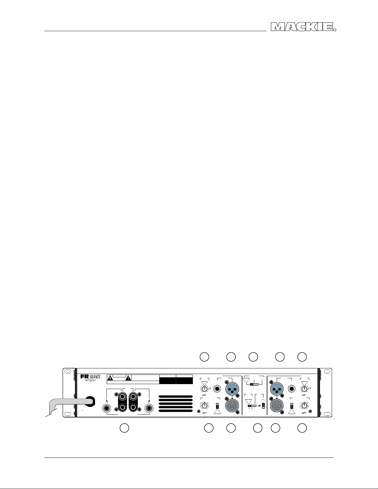
VERSIO N 1.1
REAR PANEL
1. SPEAKER O UTPUTS
The M•1400 ha s Spe a ko n
mo d e ls ha ve b ind ing po sts. Fo r b ridg e d mo no o p e ra tio n, the + o utp ut c o m e s fro m
c ha nne l o ne ’s po sitive te rmina l a nd - fro m c ha nne l two ’s po sitive .
c o nne c to rs whe re the M•1200 ha s ¼” sp e aker o utp uts. Bo th
2. INPUT
The M•1200/ M•1400 ha s b o th XLR and ¼” TRS inp uts. The y a re e le c tric a lly ide ntic a l
(w ire d in p a ra lle l). In b rid g e d m o no o r p a ra lle l m o no mo d e c ha nne l 2 inp ut is d isa b le d .
3. THROUGH
Ye t a no the r ja c k wire d in p a ra lle l with the Inp uts, the thro ug h ja c k pro vid e s a
c o nve nie nt w a y to c ha in a m p lifie rs o r p a ss the sig na l to a ny o the r d e vic e .
4. LO W CUT FILTER
Swe e ps the b uilt in hig h p a ss filte r fro m 10Hz to 170Hz.
5. C O NSTANT DIREC TIVITY HO RN EQ / AIR EQ
Built in she lving EQ p ro vide s hig h fre q ue nc y c o mp e nsa tio n whe n using c o nsta nt
d ire c tivity ho rns.
6. AMP MO DE
Thre e po sitio n slid e switc h se le c ts STEREO , PARALLEL MO NO o r BRIDG E MO NO o p e ra tio n.
C ha nne l O ne ’ s inp ut sig na l is use d fo r PARALLEL MO NO a nd BRIDG E MO NO o pe ratio n.
AMP MODE a nd O UTPUT APPLIC ATIO N switc he s sho uld no t b e c ha ng e d while the unit is
o n.
7. O UTPUT APPLICATIO N
Pla c ing the thre e p o sitio n slid e switc h in its c e nte r p o sitio n d e fe a ts the b uilt in LIMITER fo r
b o th c ha nne ls. Se le c ting SUB WO O FER e ng ag e s the b uilt in lo w pa ss filte r. The
FREQ UENC Y switc h se le c ts b e twe e n 125Hz a nd 63Hz c uto ff fo r the lo w p a ss filte r. In SUB
WO O FER m o d e , inputs 1 a nd 2 a re summe d re g a rd le ss o f AMP MO DE se tting .
(Re m e mb e r, huma n he a ring is una b le to d isc e rn d ire c tio n a t fre q ue nc ie s whe re the
wa ve le nth is g rea te r tha n the dista nc e b e twe e n yo ur e a rs, ~250Hz unle ss yo u ha ve a
g ro ssly larg e he a d!)
(MONO BRIDGE)
1200 WATTS
4 OHM LOAD MIN.
600 W A TTS CH
2 OHMS LOAD MIN.
120 VAC 50/60 Hz
1500 WATTS
CAUTION
MONO
BRIDGE
+
+
SPEAKER OUTPUTS
-
CH
2
+
--
CH
1
1 5
4 62
/ BRIDGE / MONO
CHANNEL
LOW CUT
FILTER
BALANCED
O
TYPICAL
RUNBALANCED
35 Hz
STAGE
MONITOR
100 Hz
170 Hz
OFF
CONSTANT DIRECTIVITY
HORN EQ/AIR EQ
4.5
k
Hz
ON
6k Hz2k Hz
AIR EQ
OFF
TYPICAL
INPUT
3 7
STEREO
TYPICAL
OUTPUT APPLICATION
FULL
RANGE
(
CH1 & CH2)
LIMITER
STEREO
TYPICAL
ON
AMP MODE
MONO BRIDGE
OFF
WOOFER
SUB
FREQUENCY
125Hz
63Hz
2
THRUTHRU
4
CHANNEL
HORN EQ/AIR EQ
LOW CUT
FILTER
TYPICAL
21
35 Hz
STAGE
MONITOR
100 Hz
170 HzOFF
4.5k Hz
6k Hz2k Hz
AIR EQAIR EQ
AIR EQ
INPUT
BALANCED
O
UNBALANCED
R
CONSTANT DIRECTIVITY
ON
OFF
TYPICAL
53
SYSTEM OVERVIEW
5
Page 46

SPEC IFIC ATIO NS
M•1200/M•1400 SERVIC E MANUAL
C O NTINUO US AVERAG E O UTPUT
POWER, BO TH C HANNELS DRIVEN:
M• 120 0
225 wa tts pe r c ha nne l into 8 o hms fro m 20Hz to
20kHz, with no mo re tha n 0.025% THD
400 wa tts pe r c ha nne l into 4 o hms fro m 20Hz to
20kHz, with no mo re tha n 0.050% THD
600 wa tts pe r c ha nne l into 2 o hms fro m 20Hz to
20kHz, with no mo re tha n 0.095% THD
Bridg e d mono o p e ration:
800 wa tts into 8 o hm s fro m 20Hz to 20kHz, with
no mo re tha n 0.050% THD
1200 wa tts into 4 o hms fro m 20Hz to 20kHz, w ith
no mo re tha n 0.095% THD
Ma ximum Po w e r a t 1% THD:
250 wa tts p e r c ha nne l into 8 o hms
425 wa tts p e r c ha nne l into 4 o hms
640 wa tts p e r c ha nne l into 2 o hms
850 wa tts into 8 o hms b rid g e d
1280 wa tts into 4 o hms b rid g e d
M• 140 0 / M• 140 0i
250 wa tts pe r c ha nne l into 8 o hms fro m 20Hz to
20kHz, with no mo re tha n 0.012% THD
425 wa tts pe r c ha nne l into 4 o hms fro m 20Hz to
20kHz, with no mo re tha n 0.025% THD
630 wa tts pe r c ha nne l into 2 o hms fro m 20Hz to
20kHz, with no mo re tha n 0.050% THD
Bridg e d mo no o p e ra tio n:
850 wa tts into 8 o hm s fro m 20Hz to 20kHz, with
no mo re tha n 0.025% THD
1260 wa tts into 4 o hms fro m 20Hz to 20kHz, w ith
no mo re tha n 0.050% THD
Ma ximum Po we r a t 1% THD:
300 wa tts p e r c ha nne l into 8 o hms
500 wa tts p e r c ha nne l into 4 o hms
700 wa tts p e r c ha nne l into 2 o hms
1000 wa tts into 8 o hms b rid g e d
1400 wa tts into 4 o hms b rid g e d
No te: Po w e r ra ting s a re sp e c ifie d a t
120VAC (U.S. a nd C a na d a ) a nd 240VAC
(Expo rt) line vo lta g e s.
The M•1200/ M•1400 p o we r a m p lifie rs d ra w
la rg e a mo unts o f c urre nt fro m the AC line with
c o ntinuo us sine wa ve te sting . A c c ura te
me a sure m e nt o f p o we r re q uire s a stea d y a nd
sta b le AC sup p ly. This me ans the line
imp e d a nc e m ust b e ve ry lo w to insure tha t the
p e a k AC line vo lta g e do e s no t sa g to le ss tha n
97% o f its va lue .
If d riving hig hly re a c tive lo a ds, w e re c o mme nd
tha t the lim ite r c irc uit b e e ng ag e d.
POWER BANDWIDTH:
20Hz to 70kHz (+0, –3 dB)
FREQ UENC Y RESPONSE:
20Hz to 40kHz (+0, –1 dB)
10Hz to 70kHz (+0, –3 dB)
DISTO RTIO N:
THD, SMPTE IMD, TIM < 0.025% @ 8Ω
< 0.050% @ 4Ω
< 0.150% @ 2Ω
SIGNAL-TO -NOISE RATIO :
> 107 d B be lo w ra te d p o we r into 4 o hms
C HANNEL SEPARATIO N:
> 80 d B @ 1kHz
DAMPING FAC TOR:
350 minimum
INPUT IMPEDANC E:
20k b a la nc e d b rid g ing
INPUT SENSITIVITY:
1.23 vo lts (+4 d Bu) fo r ra te d p o we r into 4 o hms
G AIN:
30.25 d B (32.5V/ V)
MAXIMUM INPUT LEVEL:
9.75 vo lts (+22 d Bu)
6
SPEC IFIC ATIO NS
Page 47

VERSIO N 1.1
RISE TIME:
< 4.4µs
SLEW RATE:
Vo lta g e Sle w Rate > 50V/ µs
> 100V/ µs b rid g e d
C urre nt Sle w Rate > 32A/ µs a t 2Ω
C MRR:
> 40 d B, 20Hz to 20kHz
LO AD ANGLE:
8(±jx) time ind e pe nd e nt a t 8Ω
4(±jx) time d e p end e nt, T > 6 min. a t 4Ω
2(1±jx) time d e p e nde nt, T > 2 m in. a t 2Ω
TRANSIENT RECO VERY:
< 1µs fo r 20 dB o ve rdrive @ 1kHz
HIG H FREQUENCY O VERLOAD AND
LATC HING:
No latc h up a t a ny fre q ue nc y o r le ve l.
HIG H FREQUENCY STABILITY:
Unc o nd itio na lly sta b le d riving a ny re a c tive o r
c ap a c itive lo ad .
TURN ON DELAY:
3 se c o nd s
LIMITER SEC TIO N:
C o mp le me ntary Po sitive a nd Ne g ative Pe a k
De te c ting
INDICATO RS:
6 m e te r LEDs p e r c ha nne l
SIG (Sig na l Pre se nt), –20, –9, –6, –3, O L
(O v e rlo a d )
C H 1 & 2
PROTEC T LEDs
SHO RT LEDs
TEMP STATUS
C O LD/ HO T LEDs
POWER CO NSUMPTIO N:
65 wa tts a t id le
900 wa tts w ith m usic al p ro g ra m fully lo a de d
(2 o hms p e r sid e , o r 4 o hms b rid g e d )
550 wa tts w ith m usic al p ro g ra m fully lo a de d
(4 o hms p e r sid e , o r 8 o hms b rid g e d )
850 wa tts a t full p o we r into 8 o hms
(c o ntinuo us sine w a ve )
1500 wa tts a t full p o we r into 4 o hms
(c o ntinuo us sine w a ve )
2500 wa tts a t full p o we r into 2 o hms
(c o ntinuo us sine w a ve )
AC LINE PO WER:
US 120VAC , 60Hz
Euro pe 240VAC , 50/ 60Hz
Jap a n 100VAC , 50/ 60Hz
Ko re a 220VAC , 60Hz
VARIABLE LO W-C UT FILTER:
10Hz (Off) to 170Hz, 2nd Orde r Be ssel
SUBWO O FER LOW-PASS FILTER:
Switc he d : 63Hz/125Hz, 3rd Ord e r Be sse l
C O NSTANT DIRECTIVITY HIG H
FREQ UENC Y BO O ST:
2kHz to 6kHz (+3 dB p o ints)
6 d B/ o c tave hig h-freq ue nc y she lving filter,
(she lving o c c urs a t a p p ro xima te ly 30kHz)
AC DRO P-O UT VO LTAG E:
At a p p ro xima te ly 50% o f ra te d line vo lta g e
PHYSICAL:
He ig ht 3.5 inc he s (89mm)
Width 19.0 inc he s (483mm)
De p th 15.25 inc he s (387mm)
O ve ra ll De p th 16.25 inc he s (413mm )
Ha nd le De p th 1.25 inc he s (32mm)
We ig ht 36 p o und s (16.3kg )
Sinc e w e are a lw a ys striving to ma ke o ur stuff
b e tte r at Ma c kie De sig ns b y inc o rpo ra ting ne w
a nd imp ro v e d ma te ria ls, c o m p o ne nts, a nd
ma nufa c turing m e tho ds, w e re se rve the right to
c ha ng e the se sp e c ific a tio ns a t a ny time
witho ut no tic e .
SPEC IFIC ATIO NS
7
Page 48

C IRC UIT THEO RY
Muc h o f the c irc uitry in the M•1200/ M•1400 is se lf e xp la na to ry fro m the sc he ma tic . This
se c tio n will e xp lain the uniq ue c irc uits a nd a rc hite c ture. Samp les in this se c tio n will re fer
to C ha nne l 1 (Le ft) fo r c irc uitry tha t is id e ntic a l o n b o th c ha nne ls.
INPUT C IRC UITRY
Re fe r to sc he ma tic o n p a g e 23.
The sig na l p a th b e g ins with the INPUT BO ARD. Fo llo wing C ha nne l 1’ s inp ut, sig na l is fe d
to a unity g a in d iffe re ntia l o p -a mp , U1A . The sig na l is ne xt se nt to U1B whic h se rve s a s
b o th HPF a nd C D ho rn EQ. If no t in SUBWO O FER m o d e , the sum ming a m p (U2B) a nd
LPF’ s (U3A, U3B) a re b yp a sse d . The sig na l is se nt via J11 to the ga in c o ntro l o n the
DISPLAY BOARD. Afte r the g a in c o ntro l, the sig na l is b uffe re d b y U7A, returne d to the
INPUT BO ARD a nd ro ute d to the MAIN BO ARD via J16.
C ha nne l 2’ s inp ut sig na l pa th is e le c tric ally id e ntic a l to C ha nne l 1’ s in STEREO m o d e . In
PARALLEL MO NO m o de C ha nne l 2’ s inp ut sig na l is ig no re d a nd C ha nne l 1’ s inp ut is se nt
to C ha nne l 2’ s g a in c o ntro l via SW5A. Fo r BRIDG E MO NO o pe ratio n, C ha nne l 1’ s inp ut
sig na l is inve rte d b y U2A a nd ro ute d to the MAIN BO ARD via SW5C .
M•1200/M•1400 SERVIC E MANUAL
PO WER AMPLIFIER CIRC UITRY
Re fe r to sc he ma tic o n p a g e 27.
The M•1200/ M•1400 use a c la ss AB trip le d a rling to n o utput with c o m p le me nta ry o utput
d e vic e s. The m a in p o we r sup p ly is +/ - 80V, the re is a lso a +/ - 90V sup p ly fo r the fro nt
e nd c irc uitry. C ha nne ls are mute d fo r 4 se c o nd s o n p o we r up a s C53 c ha rg e s via R203.
Muting is a c hie ve d b y turning o ff Q73, re mo ving c urre nt so urc e s fo r the diffe rentia l pa irs.
(Wa it a minute ! PAIRS? Re a d o n…)
An imme d ia te ly o b vio us d e pa rture fro m sta nd a rd d e sig ns is the Dua l Diffe re ntia ls a nd
Symme tric al Vo lta g e Am p s. The re a so ning b e hind this fro nt e nd a rc hite c ture is
a c tua lly q uite simple . Tra nsisto rs tra nsfe r c ha ra c te ristic s a re no t e ntire ly line a r, so e ve n
the b e st c o nve ntio na l fro nt e nd d e sig n will intro duc e so me d isto rtio n. Mo st a mp lifie rs
use ne g a tive fe e db a c k to re duc e this p ro b le m (c re a ting a fe w m o re in the p ro c e ss).
Ma c kie FR Se rie s a m p lifie rs ta ke a d iffe re nt a p p ro a c h. By using two c o m p le m e nta ry
“ m irro r ima g e ” fro nt e nd c irc uits a ny d isto rtio n c ause d b y no n-line a r tra nsisto r c urve s is
e ffe c tive ly c anc e le d o ut in the b ia s string , w itho ut fe e db a c k!
Ano the r d e sig n fe a ture uniq ue to Ma c kie FR Se rie s Am p lifie rs is the Ba ke r C la m p . The
Ba ke r C la m p ha s two func tio ns; 1) Pre ve nt o utp ut/ d rive r tra nsisto rs sa tura ting , 2) Drive
the LIMITER LDR. Re fe rring to the le ft ma in a m p sc he m a tic , Q27 is a c o m m o n b a se
a m p lifie r, it will turn o n if Q 31’ s c o lle c to r rise s mo re tha n two dio d e dro p s a b o ve the
+80V sup p ly, p re ve nting it fro m rising furthe r. The re a re thre e d io d e d ro p s b e twe e n
Q 31’ s c o lle c to r a nd the b a se o f drive r tra nsisto r Q 28 (D3, D2, Q29V
se e a vo lta g e g re a te r tha n o ne dio d e dro p b e lo w the +80V sup p ly, e ve n if the +80V
supp ly fluc tua te s. Q 27 a lso drive s the lim ite r LDR LED U2A. The ne g ative sid e ha s the
same c irc uit mirro re d .
). Q 29 will ne ve r
b e
8
C IRCUIT THEO RY
Page 49

VERSIO N 1.1
PRO TECTIO N CIRC UITS
Re fe r to sc he ma tic s o n pa g e s 27-29.
The M•1200/ M•1400 ha s two o utput p ro te c tio n c irc uits in a d d itio n to the ra il fuse s. The
first mute s the a m p if the o utput d e vic e s a re lo a d e d b e yo nd the ir safe o p e ra ting a re a
(SOA). The se c o nd is a c ro wb a r c irc uit tha t e nsure s the ra il fuse s b lo w if the re is DC o n
the o utp ut.
SOA PRO TEC TIO N
The SO A p ro te c tio n c irc uit se nse s the vo lta g e dro p a c ro ss the e mitte r re sisto rs muc h like
sta nd a rd VI c urrent limiting tra nsisto rs. Q 76 a nd Q 77 will turn o n if the e m itte r d ro p
e xc e ed s ~1V. If the y a re o n fo r lo ng e no ug h to c ha rg e C38 (thro ug h R159) , the SO A
p ro te c tio n c irc uit is a c tiva te d b y tra nsisto r sw itc he s Q 79 a nd Q 78.
If SOA d e te c tio n is tripp e d, the c ha nne l is mute d b y d isc ha rg ing C 53 thro ug h R200 a nd
D65, fa n sp e e d is inc re a se d , a nd the “ SHO RT” LED lig hts.
DC CRO WBARS
The DC Cro w b a r c irc uit pro te c ts spe a ke rs in the e ve nt o f a n o utput fa ilure b y b lo wing
a ll rail fuse s. SC Rs Q 21-24 a re use d to sho rt the +/ - 80V sup p ly supp lie s to g ro und .
O utp ut sig na l fro m b o th sid e s is fe d thro ug h 100K re sisto rs R90, R89 to C 21, e sse ntia lly
fo rming a LPF. DC o n e ithe r o utput will trig g e r c o m p a ra to r U4A (po sitive ) o r U4B
(ne g ative ). The SCRs are the n fire d via d rive r tra nsisto rs Q87, Q 88.
NOTE:
The LM339 c o m p a ra to r IC is use d e xte nsive ly in the
M•1200/ M•1400. It diffe rs fro m a sta nd a rd o p -a mp
use d a s a c o mp a ra to r in tha t it ha s a n o pe n
c o lle c to r o utp ut. If the vo lta g e a t the inve rting input
e xc e ed s the no n-inve rting , the LM339’ s o utp ut
switc he s to it’ s ne g a tive sup p ly. Othe rwise , the
o utp ut is o p e n.
C IRCUIT THEO RY
9
Page 50

THERMAL MANAG EMENT
Re fe r to sc he ma tic o n p a g e 29.
The M•1200/ M•1400 T-De sig n He a tsink/ Fa n c o o ls o utp ut de vic e s e ve nly a nd d o e s no t
c o lle c t dust o n the c irc uitry. The fa n o pe ra te s a t two sp e e d s, c o ntro lle d b y the
a m p lifie r. An LM35DZ mo unte d in the c e nte r o f the he a tsink p ro vide s te m p e ra ture
info rma tio n to the fa n c o ntro l a nd o ve rte mp c irc uits. The re is a lso a the rma l b re a ke r in
the p o we r tra nsfo rme r.
FAN CO NTRO L C IRC UIT
The fa n vo lta g e c o me s fro m a fe e d b a c k re g ula to r c irc uit fo rme d b y Q 91 a nd Q 92. The
o utp ut vo lta g e is p ro g ra m m e d b y the ra tio o f R209 to R211/ / R207 (/ / =p a ra lle l). Whe n
the unit is p o we re d up C 83 c ha rg e s thro ug h R241 p ro viding a 40 sec o nd d e la y b e fo re
the fa n sta rts. As C83 c ha rg e s, U6D’ s o utput switc he s to -16V, sta rting the fa n. The n
U6A’ s o utp ut switc he s to o pe n, a llo w ing U6B to inc re a se the fa n sp e e d , if trig ge re d . R240
a nd C 82 g ive the fa n e xtra vo ltag e whe n starting .
The fa n sp e e d is inc re a se d b y U6B a dd ing R211 in p a ra lle l w ith R207. (Q 91 w a nts it’s
b a se a dio d e dro p a b o ve g ro und , so Q 92 d o ub le s its Em itte r vo lta g e ). U6B is trigg e re d
b y U4D to inc re a se fa n sp e e d if;
M•1200/M•1400 SERVIC E MANUAL
• C ha nne l 1 SOA p ro te c tio n is ac tiva te d (U5C ), O R
• C ha nne l 2 SOA p ro te c tio n is ac tiva te d (U5D), O R
• The he a tsink is a b o ve 60 d e g C ( U5B) A ND p ro g ra m is d e te c te d (U4C ), O R
• The he a tsink te m p e ra ture is a b o ve 80 d e g C ( U5A).
U6C a nd Q 89 a re use d to re se t the c irc uit o n po we r d o wn. Und e r no rm a l o p e ra tio n
C 50 is c ha rg e d via D57, Ho lding Q 89 o ff. Whe n p o w e r is re mo ve d C 50 d isc ha rg e s a nd
Q 89 switc he s o n a s the ra ils c o lla p se . Whe n the vo lta g e o n Q89’ s c o lle c to r fa lls be lo w
g ro und U6 switc he s to the ne g a tive ra il d isc ha rg ing C 82 a nd C 83.
THERMAL SHUTDO WN
Extre me he a tsink o r tra nsfo rme r c o re te m p e ra ture will a c tiva te O VERTEMP. U5A
a c tiva te s o ve rte mp if the LM35DZ de te c ts he a tsink te m p e ra ture a b o ve 80 d e g C .
Fe e d b ac k re sisto r R137 re sc ale s U5A ’ s vo lta g e re fe re nc e so tha t the he a tsink must c o o l
to b e lo w 50 d e g C b efo re o ve rte m p is d e a c tiva te d . O ve rte m p c a n a lso b e a c tiva te d
b y the p o we r tra nsfo rme r the rma l b re a ke r (via Q 89) . In e ithe r c a se , b o th c ha nne l a re
mute d via D69 a nd D66.
10
C IRCUIT THEO RY
Page 51

VERSIO N 1.1
SERVIC E PRO C EDURES
MEC HANIC AL PRO C EDURES
The M•1200/ M•1400 d e sig n a llo ws e a sy re mo va l o f all c o m p o ne nts a nd a sse m b lie s.
Disasse m b ly a nd re a sse mb ly sho uld b e se lf e vid e nt. This m a nua l ha s e xplo d e d
d iag rams in the pa rts se c tio n.
Se ve ra l imp o rta nt p o ints c o nc e rning the asse mb ly:
• 4 o f the sc re w s tha t se c ure the to p c o ve r a lso ho ld the fro nt e xtrusio n ( c urve d
p iec e ) in p la c e . Whe n re mo ving the to p c o ve r, b e c a re ful tha t the fro nt e xtrusio n is
no t d ro p p e d.
• If the MAIN PC B is re mo ve d , b e sure the sma lle r he a d ma c hine sc re w s (750-050-04)
a re re p lac e d ne xt to the filte r c ap s. The la rg e r he a d m a c hine sc re w s c an a rc to the
c ap a c ito r b o dy.
• Be sure a ll tywra p s a re re pla c e d a nd tha t no wire s a re in d a ng e r o f b e ing p inc he d
in-b e twe e n the c o ve r a nd he a tsink.
REQ UIRED EQ UIPMENT LIST
• 30 MHz dua l tra c e o sc illo sc o p e
• DMM ( Must b e c a p a b le o f m e a suring 8m V DC with a minim um o f 2 d ig its o f
a c c ura c y, a nd d o wn to .1Ω)
• Sine w a ve o sc illa to r / Func tio n g ene ra to r (20Hz - 20KHz)
• 4 lo a d re sisto rs (8Ω with a m inim um 500W p o we r ra ting )
• 10A / 120V Va ria c With AC vo ltm e te r a nd a d e fe a ta b le a mme te r (1 Amp full ra ng e )
o r wa ttme te r (300 Wa tts full rang e )
• 0.1uF 400V film c a p a c ito r insta lle d a c ro ss dua l b a na na p lug
• 16 A WG sho rting jump e r installe d a c ro ss d ua l b a na na p lug
REC O MMENDED EQ UIPMENT LIST (PERFO RMANCE VERIFICATIO N)
• Disto rtio n a na lyzer a nd lo w d isto rtio n o sc illa to r.
(C a p a b le o f re so lving d isto rtio n a s lo w a s 0.002% fro m 20Hz to 20KHz)
• 2500W AC p o we r so urc e .
SERVIC E PRO C EDURES
11
Page 52

M•1200/M•1400 SERVIC E MANUAL
TRO UBLESHO O TING TIPS - O UTPUT FAILURES
Afte r a c a ta stro phic fa ilure , it is like ly tha t the fo ur +/ -80V sup p ly fuses will b e b lo w n.
Re p lac e fuse s a nd ve ry slowly b ring up the Va ria c while m o nito ring line c o nsum p tio n. It
is like ly tha t sub sta ntia l line c urre nt will be p ulle d due to sho rte d o utput p a rts. At the
same time , lo o k fo r DC o ffse t a t the o utp ut. O ffse t o f g re a te r tha n +/ - 2.8V w ill trig g e r
the p ro te c tio n c irc uits a nd re -b lo w the fo ur fuse s. Ke e p the o utput o ffse t b e lo w +/ - 2V,
o r te m p o ra rily d e fe a t the DC-o ffse t d e te c to r (Lift o ne sid e o f D56).
Re mo ve the ma in b o a rd fro m the unit a nd c he c k fo r sho rte d o utput tra nsisto rs. If o ne
b a d o utp ut is fo und , re p lac e a ll e ight in the c ha nne l. Whe n a n o utput d e vic e sho rts it
c an p la c e hig h c urre nt stre sse s o n the o the r o utp ut pa rts. The se o utput p a rts c a n fa il
o ve r time . Sinc e lo ng te rm re liab ility is p a ra mo unt, ple a se re p lac e a ll the o utputs.
All e ig ht o f the 3W 0.22Ω e m itte r re sisto rs must b e ve rifie d fo r pro pe r va lue . Any o ff-
to le ra nc e, o r o p e n p a rts, ne e d to b e re p la c e d . An o ff to le ra nc e (hig he r re sista nc e )
e mitte r re sisto r will p re ve nt it’ s re la te d o utput tra nsisto r fro m “ d o ing it’ s sha re ” a nd w ill
p lac e m o re stre ss o n it’ s ma te s in the o utp ut se c tio n. Also ve rify the 8 b a se d rive re sisto rs
(2.2Ω, 1/ 4W, fusib le ) a re a ll O K. Ve rify tha t the d rive rs and p re-d rive rs a re no t sho rte d . If
o ne drive r is sho rte d re p lac e it’ s ma te . Do the sa m e with the p re -d rive rs. Also c he c k a ll
the re sisto rs surro und ing the drive rs and p re -d rive rs.
C he c k the VI limite rs a nd d e te c to rs. It is no t unc o m m o n to d a m a ge the se p a rts whe n
the a mp lifie r fa ils in a sp e c ta c ula r w a y! Lo o k fo r sho rts o n Q76, Q77, Q 94, Q 95, Q 83,
Q 84, Q 96, a nd Q 97. Ve rify p ro p e r va lue o n the re sisto rs tha t g o to the b a se s o f the se
d e vic e s. It is c ritic a l tha t the se se c tio ns a re wo rking c o rre c tly. Sho rte d tra nsisto rs c a n
c ause so m e o dd a symme tric al c lipp ing pro b le m s. O p e n p a rts will no t a llo w the c urre nt
limiting to o pe ra te e ffe c tive ly. If p ro b le ms e xist in the se se c tio ns the amp lifie r mig ht fa il
into a sho rt, o r m ig ht c lip p re m a ture ly w he n lo a d e d to 2Ω.
All o f the a bo ve tro ub le sho o ting (No t inc lud ing p a rt re p la c e me nt) takes pe rha p s 15 to
30 m inute s to d o . If yo u ta ke the time , a nd d o a ll tha t is ind ic a te d a bo ve , it will allo w
99% o f the a mp lifie rs to c o me up the first time ! Trying to hurry, a nd skip p ing w ha t is
sug g e ste d , c an lea d to a frustra ting a nd time c o nsum ing re p a ir.
Slo w ly b ring up the sup p ly a nd ve rify tha t line c o nsump tio n isn’ t e xc e ssive a nd tha t the
o utp ut is c e nte re d (no DC o ffse t). It mig ht b e d e sira ble to d e fe a t the a mp lifie r muting
(C o nne c t U5-12, 13, & 14 to g e the r) te m p o ra rily so the a m p lifie rs are a c tive e ve n w he n
the sup p lie s a re still ve ry lo w. If the a m p sta ys c e nte re d , ve rify tha t it will pa ss a nic e
c le an sine w a ve . Re mo ve a ny te st jum p e rs (I.E. DC -fa ult d e fe a t & muting d e fe a t) a nd
p ro c e e d to the “ Re lia b ility Ve rific atio n” se c tio n.
12
SERVIC E PRO C EDURES
Page 53

VERSIO N 1.1
BIAS AND TEST PRO C EDURE
Afte r the unit ha s b e e n re pa ire d , the fo llo wing sho uld b e d o ne to a ssure lo ng te rm
re lia b le o p e ra tio n. If a d isto rtio n a na lyze r is pre se nt, d isto rtio n spe c ific atio ns sho uld b e
ve rifie d .
1. Ad justs bia s in b o th c ha nne ls (R1 & R51) fo r 8m V +/ - 0.3mV a t b ia s te st po ints (J53 &
J54) a fte r unit ha s id le d fo r a fe w m inute s. With Full AC line vo lta g e a p p lie d to unit,
it will p ull a ro und 65W fro m the line (900mA a t 120V). Me a sure fo r DC o ffse t o n b o th
o utp ut c o nne c to rs. DC o ffse t sho uld b e less tha n +/ - 50m V.
2. Ap p ly a 1KHz sine w a ve to the inputs a nd ve rify tha t the unlo a d e d o utp uts ha ve a
wa ve fo rm tha t is sym m e tric a l a nd und isto rte d . Drive the o utputs into c lipp ing a nd
ve rify symme tric a l “fla t-to p p ing ” o n the wa ve fo rm.
3. Re d uc e o utput le ve ls, install the 0.1uF c a p a c ito r jump e r fro m the o utp ut to g ro und
c o nne c tio ns, a nd ve rify tha t c lipp ing be ha vio r is p ro p e r. Ve rify tha t no hig h
fre q ue nc y o sc illa tio n o c c urs ne ar a nd a t c lipp ing (p a ra sitic o sc illa tio n).
4. Re m o ve c a p a c itive lo a d ing a nd m inimize sine o utp ut. Ve rify a nd re -a d just b ia s if
re q uire d . No te tha t the b ia s will no t d rift a p p re c ia bly in a unit tha t is func tio ning
p ro p e rly.
5. C o nne c t the a m p lifie r d ire c tly to the AC line a nd c o nne c t a n 8Ω d ummy lo a d to
b o th c ha nne ls. Bring sine w a ve le ve l up o n b o th c ha nne ls a nd ve rify sym m e tric a l
c lipp ing . The o utput will c lip so m e w he re b e twe e n 120V - 140V p k/ p k de p e nd ing o n
ho w stiff the line is. C lip p ing sho uld b e a s de sc rib e d a b o ve . Ad d the 0.1uF
c ap a c itive lo a d ing a nd ve rify c lip p ing is still we ll b e ha ve d .
6. Ind ivid ua lly lo a d Cha nne l 1 a nd C ha nne l 2 with 2Ω. Clip p ing sho uld b e
symme tric al, we ll b e ha ve d , a nd o c c ur so m e w he re a ro und 80V - 100V p k/ p k. Ve rify
tha t c lipp ing is we ll b e ha ve d a fte r a d d ing the 0.1uF c a p a c itive lo a d ing .
7. Re d uc e o utput le ve l to 20V p k/ p k a nd sho rt first c ha nne l o ne a nd the n c ha nne l
two . The fro nt p a ne l “sho rt” a nd “ p ro te c t” LEDs sho uld fla sh o n the re sp e c tive
c ha nne ls.
8. Pla c e a mp lifie r in b rid g e m o de a nd c o nne c t 4Ω lo a d ing to brid g e o utputs (a c ro ss
b o th “ +” o utp ut b ind ing po sts). Slip so me c a rd sto c k b e twe e n the he atsink-o utle ts
a nd c ha ssis sid e s. Mo nito r o ne o f the o utputs a nd a d just fo r a 20V p k/ p k sig na l.
Sho rt a c ro ss b o th o utputs and ve rify tha t a ll fo ur ‘ Sho rt” a nd “ Pro te c t” LEDs lig ht and
the a mp lifie r mute s.
9. Re m o ve sho rt, mo nito r o ne o f the o utputs, a nd a d just fo r a 60V p k/ p k sine o utput
(450W o f o utput p o we r b rid g e d ). Afte r a fe w m inute s the fa n w ill be g in running fa st
(he a tsink a t 60°C ) a nd a sho rt tim e late r the a m p lifie r w ill mute (he a tsink a t 80°C).
The “ Ho t” a nd “ p ro te c t” LEDs w ill c o m e o n. Re m o ve c a rd sto c k a nd a fte r a fe w
minute s the a m p lifie r will c o m e o ut o f m ute mo de a nd the “c o ld ” LED will re turn.
10. Disc o nne c t lo ad ing a nd re m o ve drive . Re c o nne c t a m p lifie r to Va ria c a nd c o nfirm
tha t the id le c o nsump tio n is ro ug hly 65W o r 900mA, a s b e fo re . C o nne c t the
a m p lifie r to sp e ake rs a nd ve rify tha t it so und s OK w ith m usic .
SERVIC E PRO C EDURES
13
Page 54

M•1200/M•1400 SERVIC E MANUAL
(THIS PAG E UNINTENTIONALLY LEFT BLANK), THO SE RESPONSIBLE HAVE BEEN PUT TO THE SWO RD
14
SERVIC E PRO C EDURES
Page 55
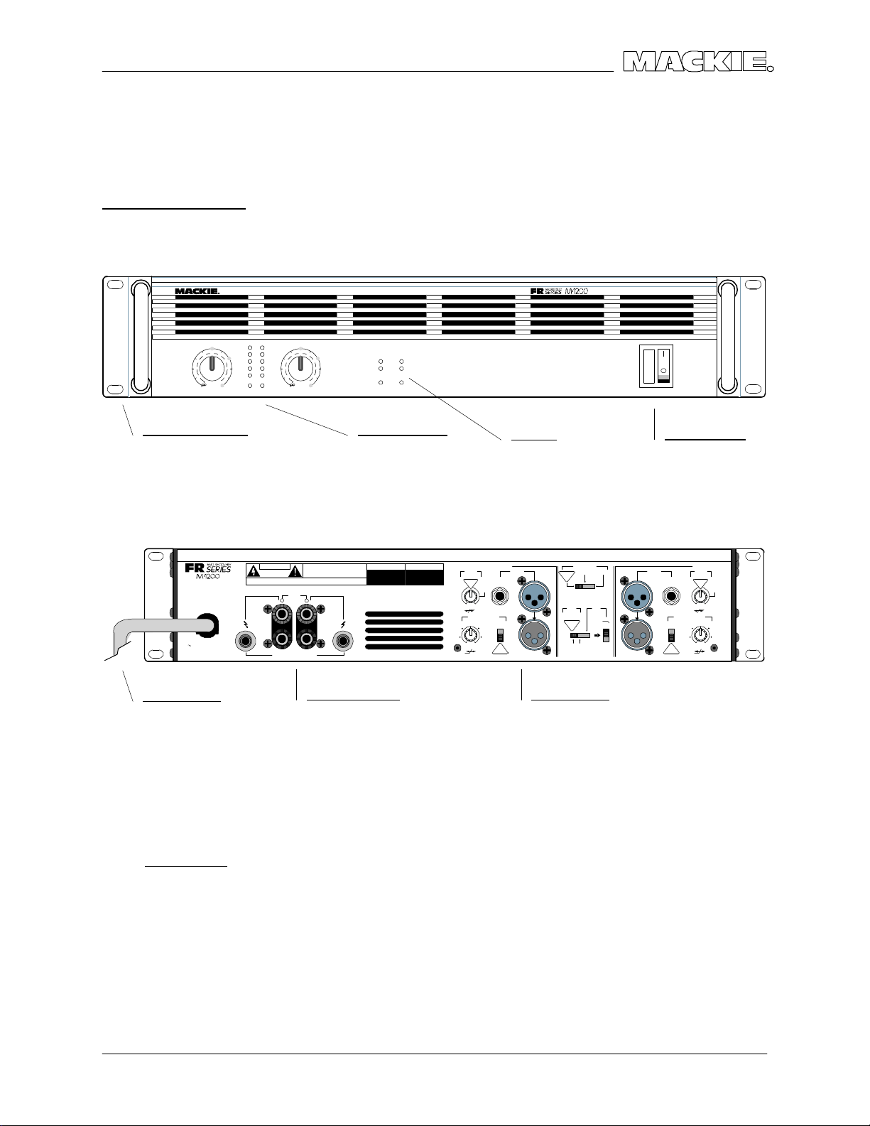
VERSIO N 1.1
PARTS
Q UICK PARTS
FRO NT PANEL
CH
GAIN/dB CH
3v
1
20
2218
2v
2
1
4
6
26
1
4
28
8
30
1v
1.23v (+4dBu)
SENSITIVITY
PR OFE SS IO NA L POW ER AMP LIFIE RFULL S YMM ETRY D UAL D IFFER ENTI AL HI GH CU RRE NT DE SIGN
OL
-3
-6
-9
-2
0
SIG
3
L
-3
-6
14
-9
-2
0
SIG
SENSITIVIT
2
v
2
1
2
0
8
2
2
2416
v
2
6
8
2
8
3
0
1v
1.23v (+4dBu)
Y
GAIN/dB
O
CH1CH
INTERNALSTATUS
PROTECT
SHORT
TEMP STATUS
CH
1&2
COLDHOT
2
ON
OFF
POWER
HANDLE ASSEMBLYS
RIG HT, 080-023-10
LEFT, 080-023-20
SC REW(TO C HASSIS),700-028-04
REAR PANEL
(MONO BRIDGE)
1200 WATTS
4 OHM LOAD MIN.
600 W A TTS CH
2 OHMS LOAD MIN.
120 VAC 50/60 Hz
1500 WATTS
AC LINE C ORD
US, 640-006-00
EURO PE, 640-007-01
JAPAN, 640-007-02
ENGLAND, 640-007-03
ITALY, 640-007-04
AUSTRALIA, 640-007-05
SWITZERLAND, 640-007-06
STRAIN RELIEF
740-004-00
INTERNA L FUSES
RAIL FUSES;
10A 5X20MM, 510-021-00
MAIN FUSE;
20A, 510-017-00
8A, 510-023-00
G AIN C O NTRO LS
5KL PO T, 130-036-00
KNOB, 760-061-00
NUT, 705-013-00
ALL LEDS
RED T-1, 304-001-00
G REEN T-1, 304-004-00
PO WER SWITCH
500-022-00
STAR WASHER, 710-023-00
CAUTION
MONO
BRIDGE
+
-
CH
1
+
CH
2
+
--
SPEAKER OUTPUTS
SPEA KER O UTPUTS
BINDING POSTS, 400-119-00
BINDING POST SCREW, 700-011-00
CHANNEL
OFF
/ BRIDGE / MONO
LOW CUT
FILTER
TYPICAL
35 Hz
STAGE
MONITOR
100 Hz
170 Hz
CONSTANT DIRECTIVITY
HORN EQ/AIR EQ
k
Hz
4.5
6k Hz2k Hz
AIR EQ
BALANCED
INPUT
O
RUNBALANCED
ON
OFF
TYPICAL
STEREO
TYPICAL
OUTPUT APPLICATION
FULL
RANGE
(
CH1 & CH2)
LIMITER
STEREO
TYPICAL
ON
AMP MODE
MONO BRIDGE
OFF
WOOFER
SUB
FREQUENCY
125Hz
63Hz
INPUT SEC TIO N
ALL KNO BS, 760-048-04
LO W CUT, 50KZx2 POT, 130-017-02
INPUT
THRUTHRU
BALANCED
UNBALANCED
TYPICAL
O
R
ON
OFF
CHANNEL
CONSTANT DIRECTIVITY
HORN EQ/AIR EQ
LOW CUT
FILTER
TYPICAL
21
35 Hz
STAGE
MONITOR
100 Hz
170 HzOFF
4.5k Hz
6k Hz2k Hz
AIR EQ
AIR EQAIR EQ
C D HO RN EQ , 10KC PO T, 130-037-02
M• 12 00 / M•1400i
¼” JAC K, 400-118-00
WASHER, 710-019-00
SLOTTED NUT, 705-015-00
M• 14 00
SPEA KON, 400-138-00
SC REW, 700-055-00
¼” INPUT JACK, 400-214-00
¼” JAC K WASHER, 710-002-00
¼” JAC K NUT, 705-003-00
MALE XLR JAC K, 400-142-00
FEMA LE XLR JAC K, 400-141-00
XLR JAC K SCREWS,700-055-00
DP3T SWITC HES, 500-023-00
DPDT SWITC HES, 500-024-00
PARTS
15
Page 56
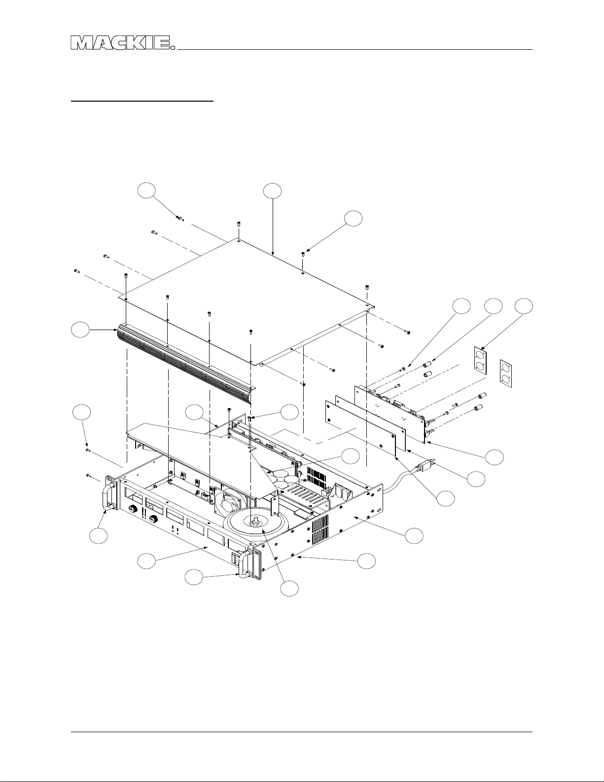
C HASSIS ASSEMBLY
M•1200/M•1400 SERVIC E MANUAL
1
4
1 7
2
3
16 17 1 8
5
6
15
16
10
14
13
8
9
11
12
PARTS
1
Page 57

VERSIO N 1.1
C HASSIS ASSEMBLY PARTS LIST
ITEM # PART # DESCRIPTIO N NOTES
1 700-028-02 SEMS 6-32X3/ 8 PHP BLKZC ALL SIDE PANEL SCREWS
2 550-221-00 TO P C O VER - M1200
3 700-041-04 MC H 6-32X3/ 8 FL 100DG BLK TO P C O VER TO CHASSIS
4 551-029-00 EXTR SC RN DSPLY BZL-M1200
4 551-029-10 EXTR SC RN DSPLY BZL-M1400
5 700-041-04 MC H 6-32X3/ 8 FL 100DG BLK MANIFOLD TO FA N
6 550-277-00 SC REEN MANIFO LD - M1400
7 550-223-20 SIDE RAIL LEFT - M1200
8 550-223-10 SIDE RAIL RIGHT - M1200
9 550-222-00 BTM C OVER - M1200
9 550-244-00 BO TTO M COVER - M1400
10 080-023-20 PNT HANDLE ASSY LEFT
11 080-023-10 PNT HANDLE ASSY RIG HT
700-028-04 SEMS 6-32X3/ 4 PHP BLKZC HANDLE ASSY TO CHASSIS
700-041-04 MC H 6-32X3/ 8 FL 100DG BLK HEATSINK TO C HASSIS BO TTTO M
12 TRANSFORMER / MO UNTING
600-016-00 XFMR M1200 120V
600-016-01 XFMR M1200 230V
600-016-02 XFMR M1200 100V
705-019-00 NUT HEX 5/ 16-18
710-017-00 WASH SPLTLC K 5/ 16 HEAVY
710-024-00 WASH FLAT 5/ 16 HARD (USS)
550-249-00 PLATE XFMR MTG - M1200
780-111-00 RUBBER PAD
700-059-00 HEX 5/ 16-18X3IN G D-5
13 550-247-00 SHIELD INPUT - M1200
14 780-042-00 INSUL MYLAR INPUT SHIELD
15 055-079-00 PCB ASSY INPUT 1200/ 1400
16 700-028-02 SEMS 6-32X3/ 8 PHP BLKZC INPUT PC B TO SHIELD
17 760-048-04 KNOB 9MM DARK G RAY
18 550-275-00 SPAC ER PLA TE - AMPLIFIER
710-002-00 WASHER FO R ¼” JAC KS
705-003-00 NUT FOR ¼” JAC KS
700-055-00 MC H 4-24X3/ 8 PHP BLK HILO XLR JAC K SCREWS
055-080-00 PCB ASSY DISPLY 1200/ 1400
055-081-00 PCB ASSY MAIN - 1200
080-072-01 PCB ASSY MAIN - M1400
080-072-02 PCB ASSY MAIN - M1400i
700-028-02 SEMS 6-32X3/ 8 PHP BLKZC MAIN PC B TO CHASSIS EXCEPT FO R:
700-050-04 MC H 6-32X3/ 8 FIL PHL C LR ! USE THESE NEXT TO C APS !
700-011-00 MC H 4-40X1/ 4 BTNSKT BLKO X O UPTUT TERMINALS TO C HASSIS
710-019-00 WASH FIBRE BLK (W/ JAC K)
705-015-00 NUT SLOT NC KL
700-055-00 MC H 4-24X3/ 8 PHP BLK HILO
PARTS
17
Page 58
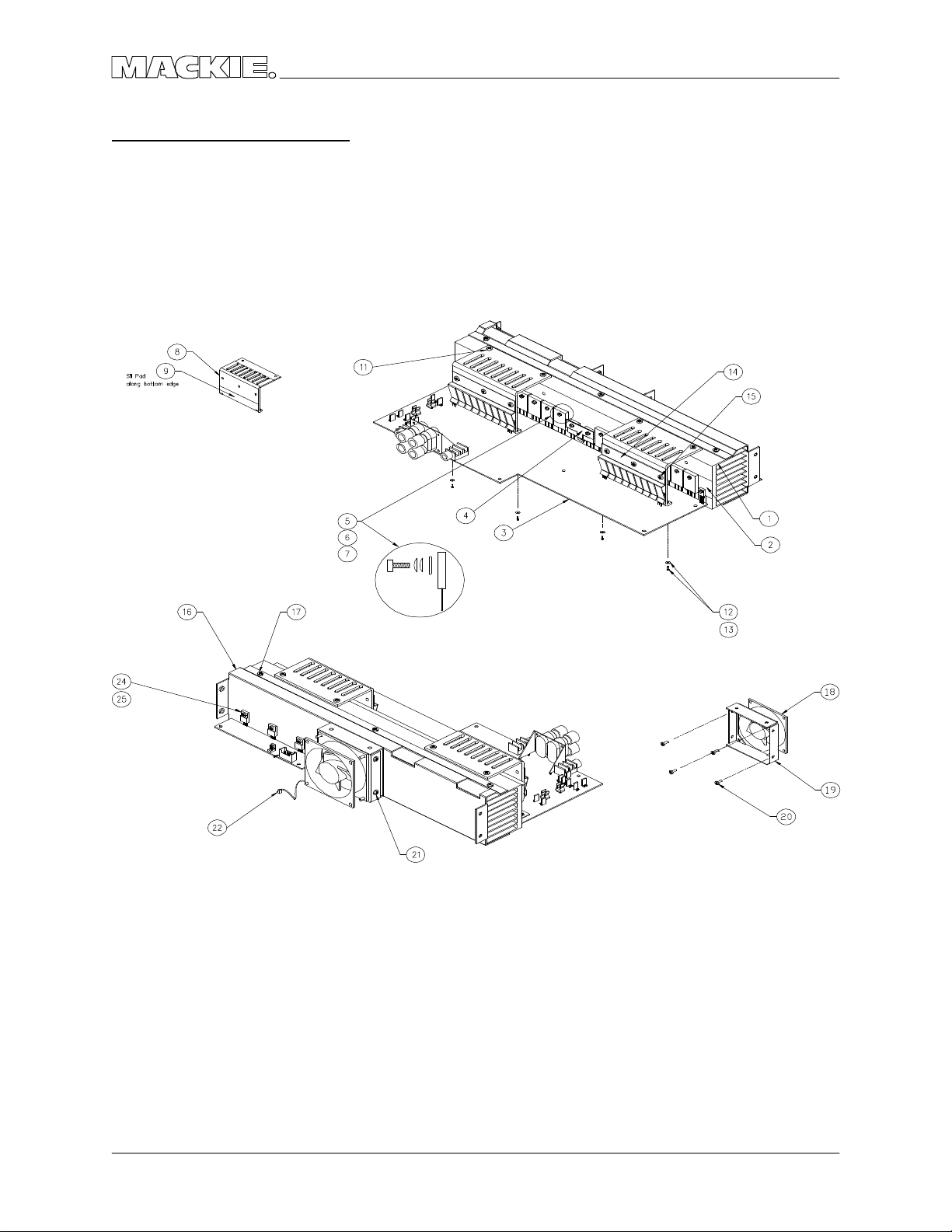
HEATSINK ASSEMBLY
M•1200/M•1400 SERVIC E MANUAL
18
PARTS
Page 59

VERSIO N 1.1
HEATSINK ASSEMBLY PARTS LIST
ITEM # PART # DESC RIPTIO N
1 551-032-00 EXTR FAB HEA TSINK - M1200
2 410-003-00 INSL SILPAD K6 W/ ADHESIVE
3 055-081-00 PC B ASSY MAIN - 1200
3 080-072-01 PC B ASSY MAIN - M1400
3 080-072-02 PC B ASSY MAIN - M1400i
4 550-255-00 PIGGYBAC K C LIP
5 700-058-02 MCH 4-40X1/ 2 SKT C LRZC
6 710-020-00 WASH NO .4 C OMPRESSIO N
7 710-022-00 WASH FLAT NO .4 FENDER
8 550-224-00 BRAC KET SUBSINK - M1200
9 410-003-00 INSL SILPAD K6 W/ ADHESIVE
11 700-010-00 TF 6-32X1/ 4 PHP BLKZC
12 710-013-00 WASH FLAT NO.6 FIBRE
13 700-010-04 TF 6-32X3/ 8 PHP BLKZC
14 550-237-00 SPRING C LIP SUBSINK-M1200
15 700-028-02 SEMS 6-32X3/ 8 PHP BLKZC
16 550-225-00 HEA TSINK C OWLING - M1200
17 700-010-00 TF 6-32X1/ 4 PHP BLKZC
18 770-006-00 FAN 80MM 24VDC -MEC HATRO NI
18 770-007-00 FAN 80MM 24VDC -PANASONIC
19 550-219-00 BRKT FAN PS - SR40.8
20 700-047-04 MCH 10-32X3/ 8 FIL PHL CLR
21 700-028-02 SEMS 6-32X3/ 8 PHP BLKZC
22 400-083-00 2P .100X1 22G A END
24 700-058-02 MCH 4-40X1/ 2 SKT C LRZC
25 710-020-00 WASH NO .4 COMPRESSIO N
PARTS
19
Page 60

C O MPLETE PARTS LIST
040- Ca b les
055- Finishe d PC B Assys
100- Po ts a nd Re sisto rs
200- Ca p a c ito rs
300- Se m ic o nd uc tors
400- Jac ks/Co nne c to rs
500- Switc he s
510- Fuses
550- Cha ssis Me tal
600- Tra nsfo rm e rs
601- Induc to rs
610- Wire s a nd Ca b les
M•1200/M•1400 SERVIC E MANUAL
640- AC Line Co rd s
700- Ha rd w a re
760- Kno b s/ Pla stic
790- Misc ./ Pac king
800- Printe d Ma teria l
PART # DESC RIPTION
040-033-02 RIB 28G A TRANS 20C 18IN
040-033-03 RIB 28G A TRANS 20C 4IN
040-117-02 RIB 28G TRNS 10C .10 11.5
055-079-00 PCB ASSY INPUT 1200/ 1400
055-080-00 PCB ASSY DISPLY 1200/ 1400
055-081-00 PCB ASSY MAIN - 1200
080-072-01 PCB ASSY MAIN - M1400
080-072-02 PCB ASSY MAIN - M1400i
080-034-00 PCB ASSY SO FT START – 120V
080-034-01 PCB ASSY SO FT START – 240V
080-023-10 PNT HANDLE ASSY RIG HT
080-023-20 PNT HANDLE ASSY LEFT
080-035-00 PWR SW HARNESS - AMP
100-001-00 RES C F .125W 5% 10 O HM
100-017-00 RES C F .125W 5% 47 O HM
100-023-00 RES C F .125W 5% 82 O HM
100-027-00 RES C F .125W 5% 120 O HM
100-030-00 RES C F .125W 5% 160 O HM
100-031-00 RES C F .125W 5% 180 O HM
100-035-00 RES C F .125W 5% 300 O HM
100-040-00 RES C F .125W 5% 430 O HM
100-042-00 RES C F .125W 5% 510 O HM
100-045-00 RES C F .125W 5% 680 O HM
100-049-00 RES C F .125W 5% 1K OHM
100-050-00 RES C F .125W 5% 1K1 OHM
100-056-00 RES C F .125W 5% 2K OHM
100-061-00 RES C F .125W 5% 3K3 OHM
100-068-00 RES C F .125W 5% 6K2 OHM
100-071-00 RES C F .125W 5% 8K2 OHM
100-072-00 RES C F .125W 5% 9K1 OHM
100-073-00 RES C F .125W 5% 10K O HM
100-075-00 RES C F .125W 5% 12K O HM
100-076-00 RES C F .125W 5% 13K O HM
100-080-00 RES C F .125W 5% 20K O HM
100-082-00 RES C F .125W 5% 24K O HM
100-083-00 RES C F .125W 5% 27K O HM
100-084-00 RES C F .125W 5% 30K O HM
100-086-00 RES C F .125W 5% 36K O HM
100-089-00 RES C F .125W 5% 47K O HM
100-092-00 RES C F .125W 5% 62K O HM
100-093-00 RES C F .125W 5% 68K O HM
PART # DESC RIPTION
100-094-00 RES C F .125W 5% 75K O HM
100-097-00 RES C F .125W 5% 100K OHM
100-109-00 RES C F .125W 5% 1M O HM
100-110-00 RES C F .125W 5% 360K OHM
100-111-00 RES C F .125W 5% 390K OHM
105-277-00 RES MF .125W 1% 750 O HM
105-331-00 RES MF .125W 1% 2K49 O HM
110-036-00 RES C F .25W 5% 300 O HM
110-046-00 RES C F .25W 5% 750 O HM
115-427-00 RES MF .25W 1% 24K9 O HM
121-097-00 RES MO 1W 5% 10K O HM
123-009-00 RES MO 3W 5% .22 O HM
123-033-00 RES MO 3W 5% 2.2 O HM
123-056-00 RES MO 3W 5% 20 OHM
123-071-00 RES MO 3W 5% 82 OHM
123-085-00 RES MO 3W 5% 330 O HM
123-109-00 RES MO 3W 5% 3.3K O HM
123-124-00 RES MO 3W 5% 13K O HM
125-020-00 RES WW 15W 5% 82 O HM CMNT
130-017-02 POT RTY 50KC 12MM DUAL TN
130-036-00 POT RTY 5KA 16MM DL DTNT
130-037-02 POT RTY 10KC 9MM TN
130-038-00 POT TRIM 500B HO RIZ
140-025-00 RES TF SM .1W 5% 10 O HM
140-057-00 RES TF SM .1W 5% 220 O HM
140-060-00 RES TF SM .1W 5% 300 O HM
140-065-00 RES TF SM .1W 5% 470 O HM
140-068-00 RES TF SM .1W 5% 620 O HM
140-073-00 RES TF SM .1W 5% 1K0 O HM
140-076-00 RES TF SM .1W 5% 1K3 O HM
140-078-00 RES TF SM .1W 5% 1K6 O HM
140-080-00 RES TF SM .1W 5% 2K0 O HM
140-081-00 RES TF SM .1W 5% 2K2 O HM
140-083-00 RES TF SM .1W 5% 2K7 O HM
140-087-00 RES TF SM .1W 5% 3K9 O HM
140-089-00 RES TF SM .1W 5% 4K7 O HM
140-092-00 RES TF SM .1W 5% 6K2 O HM
140-094-00 RES TF SM .1W 5% 7K5 O HM
140-097-00 RES TF SM .1W 5% 10K O HM
140-106-00 RES TF SM .1W 5% 24K O HM
140-108-00 RES TF SM .1W 5% 27K O HM
20
PARTS
Page 61

VERSIO N 1.1
PART # DESC RIPTION
140-111-00 RES TF SM .1W 5% 36K O HM
140-115-00 RES TF SM .1W 5% 51K O HM
140-123-00 RES TF SM .1W 5% 100K O HM
140-124-00 RES TF SM .1W 5% 120K O HM
140-139-00 RES TF SM .1W 5% 470K O HM
140-147-00 RES TF SM .1W 5% 1M O HM
145-318-00 RES MF SM .1W 1% 2K00 O HM
145-389-00 RES MF SM .1W 1% 10K0 O HM
145-397-00 RES MF SM .1W 1% 12K1 O HM
145-406-00 RES MF SM .1W 1% 15K0 O HM
145-469-00 RES MF SM .1W 1% 68K1 O HM
145-478-00 RES MF SM .1W 1% 84K5 O HM
145-485-00 RES MF SM .1W 1% 100K O HM
145-547-00 RES MF SM .1W 1% 442K O HM
150-009-00 RES FUS .25W 5% 2.2 O HM
150-037-00 RES FUS .25W 5% 33 OHM
150-045-00 RES FUS .25W 5% 68 OHM
200-001-02 PLY .012UF 10% 100V TR
200-004-02 PLY .047UF 10% 100V TR
200-007-02 PLY .01UF 10% 100V TR
200-015-02 PLY .0047UF 10% 100V PEI
200-022-02 PLY .47UF 5% 50V TR
200-023-00 PLY/ BX .001UF 20% 250V Y2
200-024-00 PLY/ BX .01UF 20% 250V Y2
200-025-02 PLY/ BX .56UF 5% 63V TR
200-036-00 PLY/ BX .1UF 10% 250V
205-002-02 MICA 270PF 5% 500V TR
210-001-02 C ER .01UF +80/ -20% 50V TR
210-010-02 C ER 47PF 5% 500V NPO TR
210-017-02 C ER 470PF 5% 500V Y5E TR
211-003-00 C ER .001UF 10% 50V AX
211-009-00 C ER .1UF 20% 50V AX
212-001-00 C ER .01UF 10% 50V X7R SM
212-004-00 C ER 220PF 5% 50V NPO SM
212-009-00 C ER 47PF 5% 50V NPO SM
212-010-00 C ER .1 +80/ -20 25V Z5U SM
220-001-02 LYT 22UF 20% 25V RAD TR
220-002-02 LYT 47UF 20% 25V RAD TR
220-004-02 LYT 470UF 20% 6.3V RAD TR
220-007-00 LYT 100UF 20% 100V RAD
220-011-02 LYT 100UF 20% 25V RAD
220-014-00 LYT 2.2UF 20% 50V RAD
220-025-00 LYT 1000UF 20% 35V RAD
220-027-02 LYT 10UF 20% 50V RAD TR
220-033-00 LYT 10000UF 20% 80V RAD
220-034-00 LYT .47UF 20% 100V RAD
220-035-00 LYT 12000UF 20% 80V RAD
220-039-00 LYT 1000 20 25V RAD SMDIA
220-040-00 LYT 10UF 20% 160V RAD
300-001-00 DIO SIG 1N4148 100V 500MW
PART # DESC RIPTION
300-003-00 DIO SW DL4148 100V SM
300-007-00 DIO SW 1SS244-SUB 1SS245
301-006-00 THY 2N6507 400V
301-007-00 DIO PWR DUAL FEP30 (D7)
301-008-00 DIO PWR DUAL FEN30 (D8)
301-009-00 DIO PWR 1N4004
301-010-00 DIO PWR 1N5404 3A 400V
301-014-00 DIO PWR 1N4007
302-001-00 DIO ZEN 1N5261B 47V 500MW
302-003-00 DIO ZEN 1N4745A 16V 1W
304-001-00 LED RED T-1
304-004-00 LED GREEN T-1
310-002-00 XSTR PNP 2N4403
310-007-00 XSTR NPN 2N4401
310-023-02 XSTR NPN 2SC2362K TR
310-028-00 XSTR PNP 2SB940A POWER
310-029-00 XSTR NPN 2SD1264A PO WER
310-032-02 XSTR PNP 2SA1016K TR
310-033-00 XSTR PNP MJL21193
310-034-00 XSTR NPN MJL21194
310-035-00 XSTR PNP 2SA1478
310-036-00 XSTR NPN 2SC3788
310-037-00 XSTR NPN MJE340 POWER
310-038-00 XSTR PNP MJE350
310-042-00 XSTR NPN MJE15032
310-043-00 XSTR PNP MJE15033
311-002-00 XSTR PNP MMST4403 SM
320-004-00 O PAMP 4560F
323-001-00 LM339 Q UAD C O MP
323-002-00 LM339D Q UAD C O MP SM
329-012-00 VTL5C 10 OPTOCOUPLER
329-014-00 LM35DZ PREC TEMP SENSO R
400-059-00 TERM QDISC .250 MALE PC MT
400-060-00 FUSE CLIP PCMT 5MM DIA
400-061-00 HDR 2P .100X1 STR LO CK
400-065-00 TERM QDISC .250 F 18-22G A
400-077-00 HDR 20P .1X2 STR LC K SHRD
400-078-00 HDR 10P .1X2 STR LC K SHRD
400-083-00 2P .100X1 22G A END
400-118-00 JAC K 1/ 4 HORIZ PCMNT MO NO
400-119-00 TERM BANANA Q UA D HRZ PCMT
400-129-00 FUSE CLIP .25 DIA PC MNT
400-133-00 HDR 6CK 11A/ 600V
400-134-00 REC P 6C K 11A/ 600V
400-135-00 TERM 11A/ 600V F 18-20G A
400-138-00 SPEA KONS HORIZ 4 C KT
400-141-00 XLR 3P F VERT A-SERIES
400-142-00 XLR 3P M VERT A-SERIES
400-143-00 HDR 3P .100X1 STR
400-171-00 HDR 2P .100X1 STR
PARTS
21
Page 62

M•1200/M•1400 SERVIC E MANUAL
PART # DESC RIPTION
400-172-00 TERM SOLDER-IN 18A WG
400-173-00 TERM .25 Q KDS PC MT STABLE
400-210-00 TERM QDISC .250 F 18-22G A
400-214-00 JAC K 1/ 4 V PCMNT 1MM WASH
410-003-00 INSL SILPAD K6 W/ ADHESIVE
500-022-00 SW RCKR ILLUMINATED
500-023-00 SW SLIDE 4P3T MINI
500-024-00 SW SLIDE DPDT MINI
501-002-00 RELA Y SPDT 30AMP 110VDC
510-017-00 FUSE SB 20A 3AB 1/ 4X1-1/ 4
510-021-00 FUSE FB 10A 5X20MM 250V
550-219-00 BRKT FAN PS - SR40.8
550-221-00 TO P C O VER - M1200
550-222-00 BTM C OVER - M1200
550-223-10 SIDE RAIL RIGHT - M1200
550-223-20 SIDE RAIL LEFT - M1200
550-224-00 BRACKET SUBSINK - M1200
550-225-00 HEATSINK C O WLING - M1200
550-237-00 SPRING C LIP SUBSINK-M1200
550-244-00 BO TTO M COVER - M1400
550-247-00 SHIELD INPUT - M1200
550-249-00 PLATE XFMR MTG - M1200
550-255-00 PIG G YBAC K C LIP
550-275-00 SPAC ER PLA TE - AMPLIFIER
550-277-00 SC REEN MANIFO LD - M1400
551-029-00 EXTR SC RN DSPLY BZL-M1200
551-029-10 EXTR SC RN DSPLY BZL-M1400
551-032-00 EXTR FAB HEATSINK - M1200
553-002-01 C RS 18G A 36 X 120
553-002-03 C RS 18G A 48 X 120
553-006-03 EG 18G A 48 X 120
553-007-03 AL .063 48 X 120
553-010-03 EG 20G A 48 X 120
553-015-03 AL .125 1100 H14 48 X 120
553-017-01 SS .048 17-7 36 X 120
600-016-00 XFMR M1200 120V
601-006-00 INDUCTOR AIR COIL 1UH
611-029-02 WIR 18GA 1007 BLK 5IN ST2
611-038-00 WR 18G 1010 G N/ YL 4IN ST2
660-005-00 22G A JUMPER WIRE
700-005-00 SEMS 8-32X1/ 2 PHP BLKZC
700-010-00 TF 6-32X1/ 4 PHP BLKZC
700-010-04 TF 6-32X3/ 8 PHP BLKZC
700-011-00 MC H 4-40X1/ 4 BTNSKT BLKO X
700-028-02 SEMS 6-32X3/ 8 PHP BLKZC
700-028-04 SEMS 6-32X3/ 4 PHP BLKZC
700-041-04 MC H 6-32X3/ 8 FL 100DG BLK
700-047-04 MC H 10-32X3/ 8 FIL PHL C LR
700-050-04 MC H 6-32X3/ 8 FIL PHL C LR
700-055-00 MC H 4-24X3/ 8 PHP BLK HILO
PART # DESC RIPTION
700-058-02 MC H 4-40X1/ 2 SKT CLRZC
700-059-00 HEX 5/ 16-18X3IN G D-5
704-001-01 PEMNUT 6-32 .038 STL
704-001-02 PEMNUT 6-32 .054 STL
704-007-01 PEMNUT 4-40X.060L SS FLSH
704-023-03 STUD 6-32X.500 STL FLSH
705-001-00 KEPNUT 6-32
705-003-00 NUT (SPLD W/ JAC K)
705-013-00 NUT HEX M7 BLK
705-015-00 NUT SLOT NC KL SPLD W/ JAC K
705-018-00 NUT HEX 5/ 16-18 (G D-5)
706-036-01 6-32X.188L STL PEM
706-036-03 STDF 6-32X.312L STL PEM
706-045-00 SPCR PVC .770 LED HI TEMP
710-002-00 WASHER (SPLD WITH JAC K)
710-013-00 WASH FLAT NO.6 FIBRE
710-017-00 WASH SPLTLC K 5/ 16 HEAVY
710-019-00 WASH FIBRE BLK (W/ JAC K)
710-020-00 WASH NO.4 C O MPRESSIO N
710-022-00 WASH FLAT NO.4 FENDER
710-023-00 WASH STAR M7 .020 THK
710-024-00 WASH FLAT 5/ 16 HARD (USS)
711-001-00 LUG NO.6 SO LDER STAR
712-020-00 BRKT A NG 6-32X.037THK STL
712-021-01 RVT CL END .125X.062-.125
740-004-00 STRAIN RELIEF HEYCO 1244
760-048-04 KNOB 9MM DARK G RAY
760-061-00 KNOB VOLUME M1200
770-006-00 FAN 80MM 24VDC -MEC HATRONI
770-007-00 FAN 80MM 24VDC -PANASONIC
780-042-00 INSUL MYLAR INPUT SHIELD
780-114-00 RUBBER WASHER - THIN
790-002-00 BAG PO LY 12 X 18 2MIL
790-016-00 BAG PO LY 24X30 4MIL-M1200
800-066-00 BO X M1200
800-069-00 BO X M1400
810-056-00 INST TO P/ BOTTO M - A MP
820-062-00 O WN MNL - M1200/ M1400
820-062-10 O WN MNL – M1400i
830-016-00 REG & WARR CA RD FR SERIES
22
PARTS
 Loading...