

Page 1
USER’S GUIDE
™
™
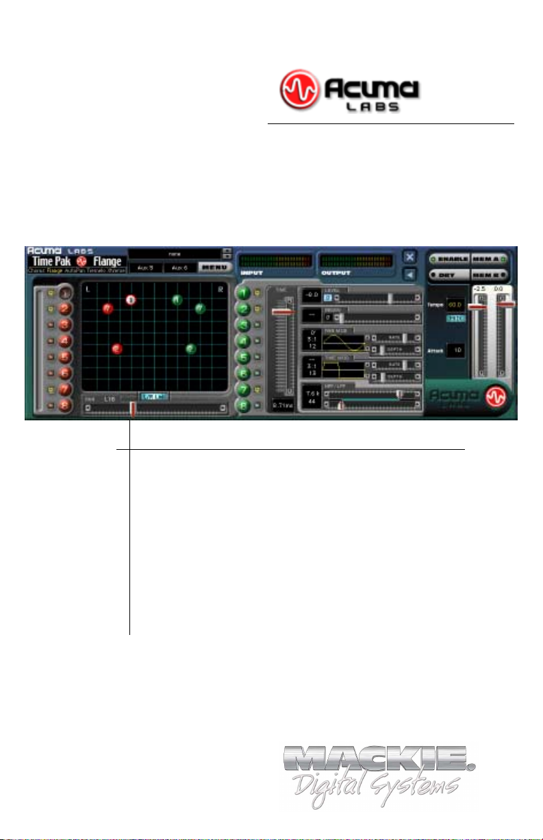
Time Pak
The ultimate in Time Modulated Effects:
Chorus, Flange, AutoPan, Tremolo, Extreme
Plug-in for Mackie Digital Mixers
™
®
Page 2

Iconography
FLYING
SAUCER
This icon identifies a description of how to
perform an action with the mouse.
This icon identifies a description of how to
perform an action from the console.
This icon will lead you to some further
explanations of features and practical tips.
This icon marks information which is very
important, so please make sure you have a read.
This icon does not appear in this guide.
“Mackie” and the “Running Man” figure are trademarks or
registered trademarks of Mackie Designs Inc. All other brand
names mentioned are trademarks or registered trademarks of
their respective holders, and are hereby acknowledged.
Part No. 820-251-00 Rev. A 02/2001
© 2001 Mackie Designs Inc. All Rights Reserved.
2
Acuma Time Pak
Page 3

Contents
Introduction ----------------------------------------4
About Acuma Labs---------------------------------------------- 4
About the D8B UFX Card -------------------------------------- 5
About Time Pak ------------------------------------------------- 5
Let’s Get Started ---------------------------------- 6
Requirements----------------------------------------------------6
Authorizing the Plug-in----------------------------------------6
Unlock Procedure -----------------------------------------------7
Configuring the Plug-in --------------------------------------- 8
Using the Time Pak Plug-in -------------------- 10
Front Panel Overview ---------------------------------------- 10
Status Block----------------------------------------------------- 11
Screen Block ---------------------------------------------------- 13
Controls Block-------------------------------------------------- 15
Global Controls Block --------------------------------------- 20
Saving, Loading, and Resetting a Preset ----------------- 23
Automation and Snapshot Control ---------- 26
FX Routing ---------------------------------------- 27
Factory Presets----------------------------------- 33
Note: Any future revisions of this guide will be available for
viewing and downloading from our website: www.mackie.com.
Further plug-in details and preset downloads can be obtained from
www.acumalabs.com.
User’s Guide
3
Page 4
Introduction
Thank you for purchasing Time Pak, the ultimate in Time
Modulated Effects from Acuma Labs. It is one of the exciting
new family of 24-bit plug-ins for the D8B, specifically designed
for the new Mackie Universal Effects (UFX) card.
Time Pak is a highly creative tool that enables you to produce
classic Chorus, Flange, Auto Pan, Tremolo and new Extreme
sounds that are guaranteed to change the way that you think of
effect processing forever. The first time that you use the visual
and easy-to-use graphic user interface (GUI), you will quickly
understand the power of this package. After experiencing the
drag and drop functions, which let you move/edit nodes in real
time, you will soon realize that Time Pak is destined to become
an integral part of the way you produce sessions from now on.
About Acuma Labs (www.acumalabs.com)
One of the newly aquired companies in the growing Mackie
family, Acuma Labs develops real-time embedded systems for
professional audio applications to create high quality products
for the music and pro audio industries. Acuma specializes in
digital audio effects using DSP, real-time operating systems,
graphical user interfaces, and digital hardware design.
4
Acuma Time Pak
Page 5

About the D8B UFX Card
The UFX card provides robust processing power for computationheavy plug-ins. The UFX card is a 4-in/4-out architecture, which
means it can support four mono, two mono and one stereo, or
two stereo sends simultaneously. Up to four UFX cards can be
installed in the D8B, allowing up to sixteen simultaneous singlechannel effects, eight stereo plug-ins, or combinations thereof.
Note:Note:
Note: It is recommended that you increase the D8B’s memory if you install
Note:Note:
more than one UFX card. Memory upgrade instructions are supplied with each
card.
About Time Pak
Each Time Pak plug-in module uses one half of a UFX card (i.e.
two audio inputs and two audio outputs). It can be routed as an
“insert” or “auxiliary” connection, which affects the final audio
output (see FX Routing on page 27) in mono, stereo or surround
panning applications (using surround bus assignments). Each of
the two input signals can have up to 8 effects working on it at a
time. The main Time Pak display uses a series of red and green
colored balls (8 left effects and 8 right effects) to represent a
total of sixteen mono or 8 fully functional stereo nodes.
You can drag and drop each node in real time to adjust the time
(vertical movement) and pan (horizontal movement), or link
nodes together in stereo as one moveable group. Each node
offers individual control of volume, regen, pan modulation, time
modulation, and high and low pass filtering, that can be added to
the mix for a vast array of sounds. Apply Phase Invert to the
Level and Regen of selected effects to create just the right feel.
Use the global controls including Tempo, Effect Input level, Dry,
Memory A and B, and Attack, as comparative editing references.
Time Pak will let you save your edits as presets and toggle
between them.
As with all of the D8B plug-ins, Time Pak lets you automate
every parameter and save it all as part of your D8B session.
User’s Guide
5
Page 6
Let’s Get Started
Requirements
• One or more Mackie UFX cards
• Mackie Real Time OS 3.0 Software
• Plug-in Software
We will assume you have successfully installed a Mackie UFX
card and Mackie Real Time OS 3.0 software upgrade. If you have
encountered problems with the installation of hardware or
software please see their associated user guides or contact
Mackie support (www.mackie.com).
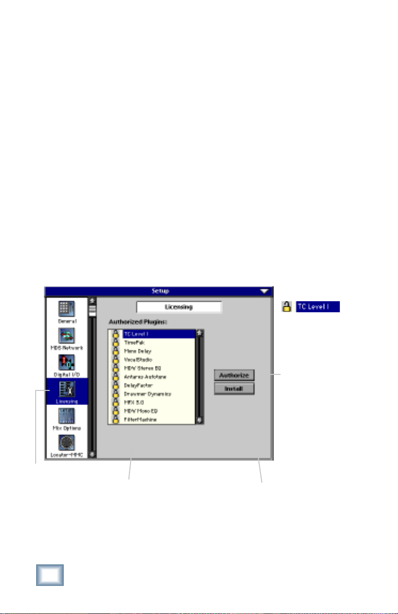
Authorizing the Plug-in
If you have D8B v 3.0 b186 or greater, the plug-in is already
installed on the D8B hard drive, however an authorized unlock
code must be entered to unlock the plug-in for normal operation.
An Unlocked
Plug-in
LICENSING
6
1234-5167-89D1
D8B Electronic Serial Number (ESN)
Acuma Time Pak
AUTHORIZE
D8B SETUP screen’s
LICENSING window
Page 7
Unlock Procedure
1. Locate your D8B’s Electronic Serial Number (ESN). This
is displayed at the bottom of the Licensing window
which is accessed from the Setup screen. The 12 digit
ESN is made from numbers 0–9 and letters A–F. It is
unique to the D8B processor, and is not the serial
number label on the rear of the control surface or CPU
chassis.
2. You will also need your plug-in’s serial number which is
printed on the floppy disk label.
3. To obtain the unlock code, have the ESN and plug-in
serial number ready. Then you have two options:
• Log on to the Mackie plug-in authorization web page:
(http://www.mackie.com/d8bauthorize.htm)
or
• Telephone Mackie Tech Support at 800-258-6883.
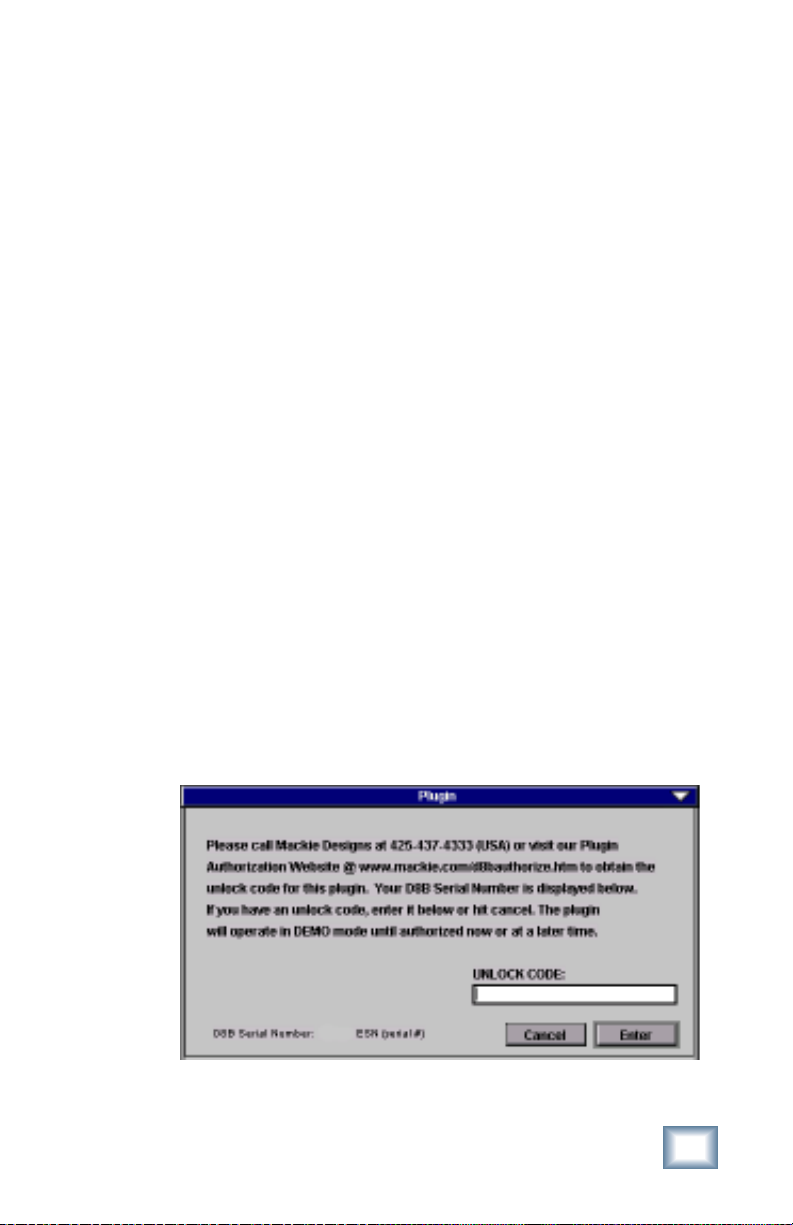
4. When you have obtained an unlock code, open the D8B
Setup window, and click Licensing.
5. With your plug-in highlighted in the Licensing window,
click Authorize, and enter your unlock code in the
UNLOCK CODE box. Click Enter, and enjoy your newly
expanded console.
User’s Guide
7
Page 8
Configuring the Plug-in
After booting the D8B you must assign the Time Pak plug-in to a
UFX card. See FX Routing on page 27 for more details.
Assign the Time Pak Plug-in to a UFX card
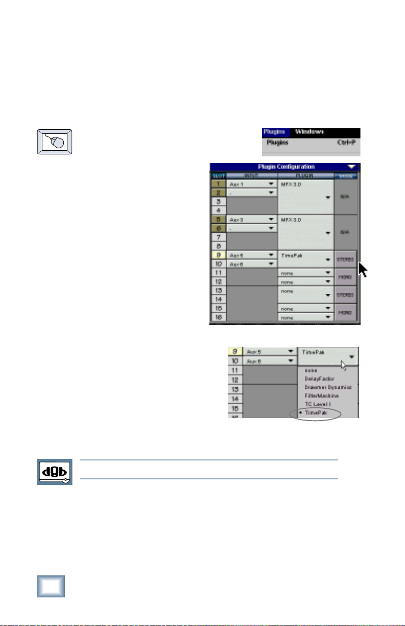
1. Click the Plugins menu and
select Plugins, (or Ctrl+P on
the keyboard).
2. In the Plugins
Configuration
window, locate the
card slot that
contains the UFX
card you wish to
assign to.
3. In the Mode column,
click the Mono/
Stereo toggle button
and set it to Stereo.
4. In the Plugin column,
select Time Pak from
the stereo plug-in drop
down menu.
Note:Note:
Note: A plug-in can also be loaded from the Setup section on the console.
Note:Note:
8
Acuma Time Pak
Page 9
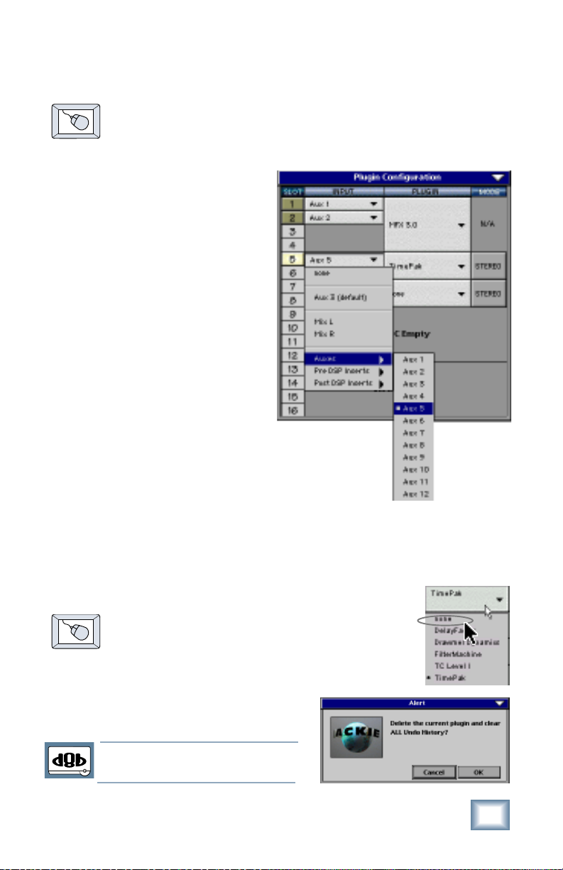
Assign an Input Source to the Plug-in
• Click the plug-in’s INPUT button to select an input
source. In the example below, we have chosen the Aux
5 Bus as the input to the plug-in installed in slot 5.
When a plug-in is fed from
an aux bus, its output
appears on the FX Return
channels (faders in the
EFFECTS bank). The return
channel is determined by
the slot number and
whether the effect output is
mono or stereo. For
example, a reverb with a
mono input and stereo
output that is installed in
Slot 5 has its outputs on FX
5 and FX 6. Note: the
default state for all FX
channels is MUTE. You
won’t hear the effect until you unmute its FX
return channel(s).
A plug-in can also receive its input from a
channel pre- or post-DSP insert or the main
stereo left and right bus. When a plug-in is inserted “in line” in
this manner, its output is routed directly back into the channel.
See FX Routing on page 27 for more details.
Removing the Plug-in
1. Select none from the associated Plugin
drop-down assignment menu.
2. Click OK in the Alert dialog box.
Note:Note:
Note: A plug-in can also be deleted
Note:Note:
from the Setup section on the console.
User’s Guide
9
Page 10
Using the Time Pak Plug-in
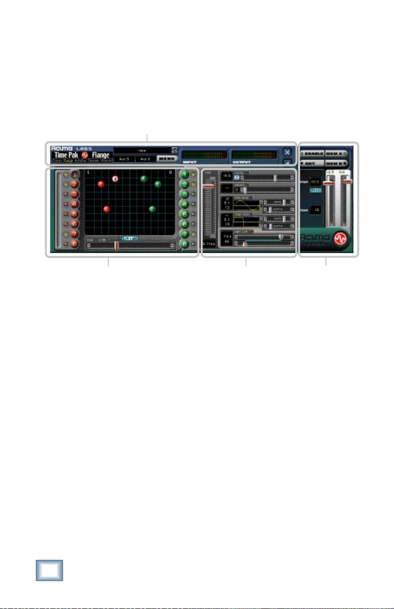
Front Panel Overview
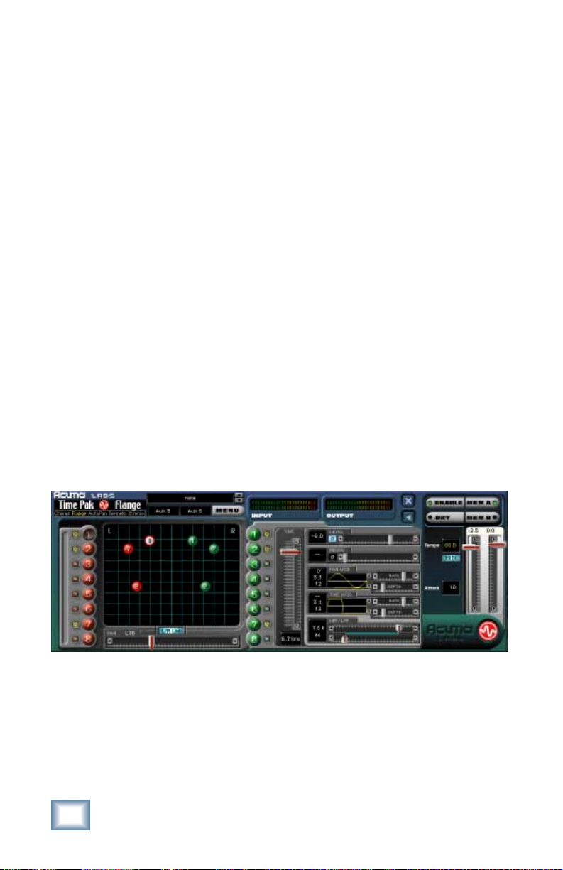
You can think of Time Pak as being broken into four blocks,
starting at the top of the GUI (Graphic User Interface) and then
moving from left to the right:
Status
Global ControlsControlsScreen
Status Block (see page 11)
The Status block includes the Mode select, where you can
choose between Chorus, Flange, Auto Pan, Tremolo, and Xtreme.
Additional functions include Preset select, Input Assign, Menu
button, Input and Output meters, and the Minimize button.
Screen Block (see page 13)
The Screen block includes: Node select buttons, the main Time
Pak Screen, mutes, Left/Right Link button and Pan slider.
Controls Block (see page 15)
The Controls block includes the Main Time Slider, Level Slider,
Pan Modulation, Time Modulation, Phase adjust, and Low Pass
and High Pass Filtering.
Global Controls Block (see page 20)
The Global Controls are located at the far right-hand side of the
GUI. These controls include the Enable select button, Dry select
button, Memory A and Memory B select buttons, Input gain
sliders, and finally the manual Tap Tempo button represented by
the Acuma logo found at the bottom right hand corner.
10
Acuma Time Pak
Page 11
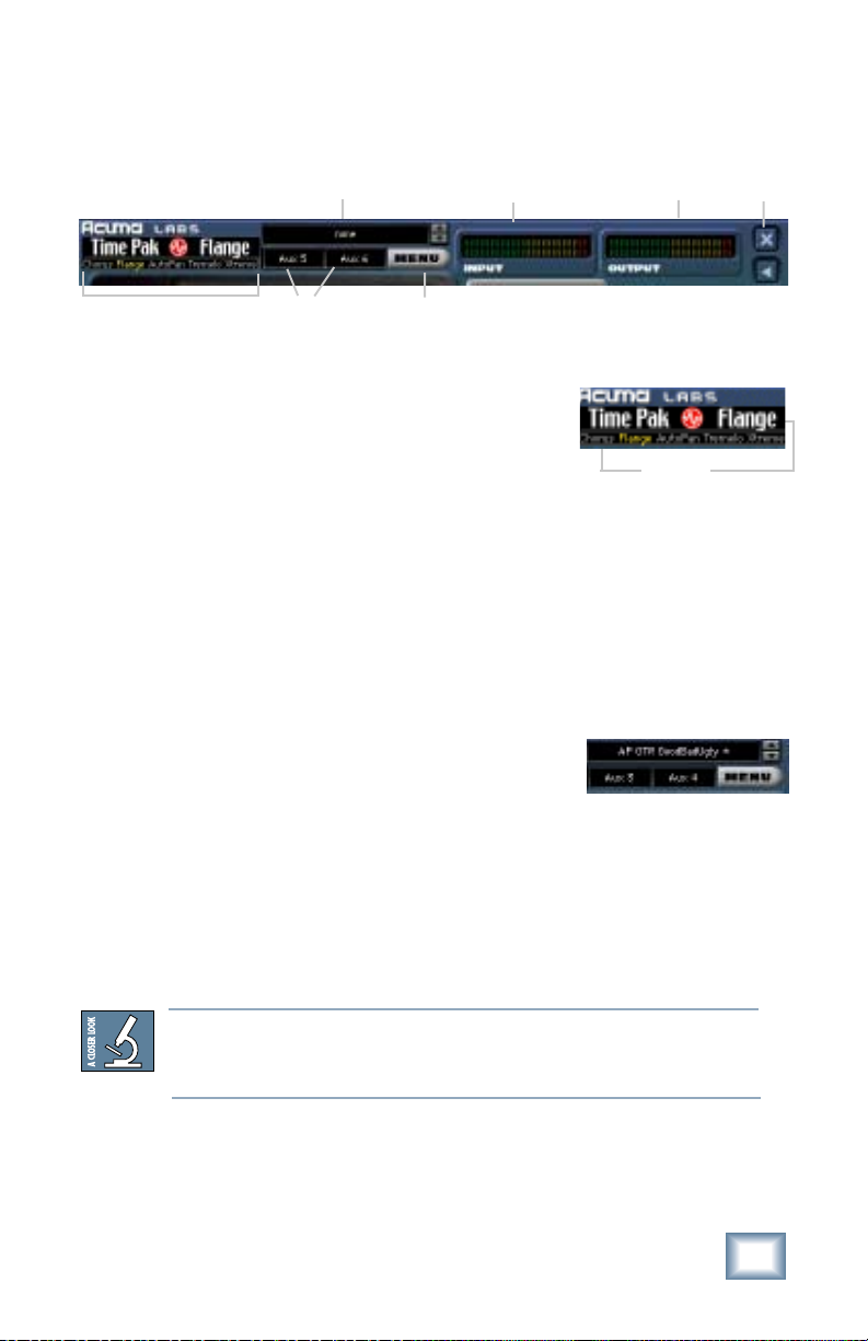
Status Block
Preset Window
Input
Meters
Output
Meters
Simplify/
Minimize
Mode Select
Input Select
Menu
Button
Mode Select
Using your mouse, click any of the effects
listed in the Mode Select block in the upper
left-hand corner of the GUI. Choose from
Chorus, Flange, Auto Pan, Tremolo and
Mode
Select
Xtreme. The selected effect will turn the typeface from white to
yellow as well as bringing up the title. Each mode has a unique
set of parameters that are associated with the selected effect.
Factory/User Presets
To open the Factory or User presets, click the Menu button and
select Load Time Pak.
Selecting one of the presets will point the
Preset Window to the preset folder,
enabling you to use the up/down arrows to
quickly select from an array of presets.
Create and edit your own presets and save
them to the User file by selecting Save as from the Menu button.
See page 33 for a table describing some of the factory presets
available. Please note that the factory presets do not make your
music sound like it was recorded in a factory.
As there is no delay in loading presets, you might try building performances by
stacking user presets and toggling between them using the up down arrows next
to the Preset window.
User’s Guide
11
Page 12

Input Select
Assign Time Pak’s stereo inputs from any of the D8B’s pre, post
or auxiliary channels.
Menu Button
This button enables familiar functions such as undo, redo, load,
save, reset, cut, copy and paste.
Input and Output Meters
The input meters represent the incoming signal from the D8B as
two rows of LEDs. The output meters represent Time Pak’s
output. The output levels are controlled by the Master Input
Sliders located on the far right-hand side of the GUI.
Minimize and Close Buttons
These buttons will minimize, expand, or close the Time Pak
window. The minimized window condenses the various sliders
and parameters into an area just below the node display. The
parameters can still be adjusted using the mouse over each box.
The meters are compressed to the left edge of the minimized
window.
Preset Window
Input
Meters
Output
Meters
Simplify/
Close
Mode Select
The meters are compressed
to fit on this side
12
Acuma Time Pak
Input Select
Menu
Button
The minimized display shows this selection of
parameters, instead of the Pan Slider.
Page 13

Screen Block
Time/Pan
display
Mutes
Nodes
Mutes
Node Select Buttons
The red and green balls are virtual representations of the
sixteen mono nodes or eight stereo pairs that can be edited in
real time using any control parameter. The ball highlighted by
white or yellow represents the currently selected node. This is a
very visual way of keeping track of your time information and
serves as a handy reference to give you a quick overview of your
edited settings.
The eight red balls on the left take their signal from the left
input and the eight green balls on the right take their signal
from the right input. Use your mouse to select a node by clicking
on any individual ball at the left or right of the screen. For
example, select the #1 red ball on the left-hand side of the
screen. You will immediately see the #1 red ball appear on the
screen. Using your mouse pointer, grab the ball and drag it
around the screen to affect its time and pan. Repeat the same
procedure to add additional nodes to the mix. Select L/R Link at
the bottom of the screen to link a red and a green ball (left and
right nodes) together as a stereo pair.
Mutes
Each of the nodes has an individual Mute button found to the
side of its corresponding colored ball. You can use Mute to turn
individual nodes on or off to help you judge their effect on the
final mix.
User’s Guide
13
Page 14

L/R Link
The L/R Link button located at the bottom of the screen enables
the selected nodes to be linked in a left/right stereo pattern and
simultaneously moved as a group using the mouse pointer.
Note: nodes are affected one node at a time unless the L/R Link is selected.
The L/R Link will not take effect until some modification has been made.
Pan Control
The Pan control slider (full
display) will enable left/right
stereo panning of selected nodes.
The same action can be achieved
by clicking the mouse on a selected node and moving it to the
left or right. In the minimized display, you can mouse over the
small PAN box at the bottom of the screen.
Left Node
Select Buttons
Mutes
14
Node Engaged
Minimized
Pa n
L/R Link
Acuma Time Pak
Time & Pan
Display
Enable Dry
Right Node
Select Buttons
The Parameters shown in the
minimized display can be
adjusted using the mouse
Mutes
Page 15

Controls Block
Master Time Slider
This vertical slider controls
the time of a selected
effect. It is measured in
milliseconds, with ranges
that vary depending on the
effect selected.
Level Control
The level control slider
determines the effect level
of any selected node, and it ranges from off (fully left) to +12 dB
(fully right).
Ganging
Clicking the word LEVEL, or any parameter name such as
PAN MOD, FREQ MOD, or HPF/LPF, causes the letters to
turn yellow and allows the parameter settings to apply to
all selected nodes. For example, if nodes 1, 2 and 3 have
level values of +3.0 dB, –3.0 dB, and +4.0 dB, clicking
LEVEL and moving the Level slider to +12 dB changes all
the selected node levels to +12 dB.
The ganged state of any given parameter will not take
effect until some modification or movement has been
made.
Polarity Inversion
The Polarity (phase) Invert button
is next to the left arrow button of
the Level control. The default is
off or non-inverted (O
and the signal is inverted (180
o
). When selected, the button turns blue
o
).
Polarity inversion adds richness to your signal and is useful
when used in conjunction with the Flange, Chorus and Xtreme
effects. It is subtle when used with the Level control and more
obvious when added to the Regen control. Effects such as
Flange and Xtreme utilize Regen control and have a Polarity
Invert next to the left arrow of the Regen control.
User’s Guide
15
Page 16

Pan Modulation
Toggle Buttons
The Pan Modulation control lets you assign
preset waveforms to modulate the pan of a
selected node. By clicking the up and down
arrows found at the right of the Pan
Modulation display, you can choose between
graphically illustrated waveform presets
representing a variety of sine waves, triangle
waves, inverted triangle, square waves, and
two separate envelope followers.
You can also change the phase of a selected
waveform by grabbing the graphic with your
mouse and moving it to the left or right,
placing the modulation in or out of phase.
The phase increments are measured in degrees and are
represented by the top set of numbers just to the left of the
waveform window.
There are two separate envelope followers
that are included in the collection of preset
waveforms. Although an envelope follower is
not technically a waveform, the regular
controls will apply. To control the threshold of
Envelope Modulation 1 and 2, use the mouse to grab the
horizontal white line that separates the window.
Note:Note:
Note: Envelope Mod 1 shifts the modulation up while
Note:Note:
Envelope Mod 2 shifts the modulation down.
The modulation RATE is controlled with a
slider and is measured in beat ratios that are
directly linked to the master tempo. The
DEPTH of the modulation is also controlled
with its own slider and is measured in
percents. The block numbers just to the left of the sliders
represent the values of the rate and depth sliders.
16
Acuma Time Pak
Page 17

Clicking the word PAN MOD causes the letters to turn yellow,
and allows the same pan modulation settings to apply to all
selected nodes.
Time
Level Slider
Regen (Flange and
Xtreme Effects only)
Pan & Freq Modulation
Rate Controls
Pan & Freq Modulation
Depth Controls
Low Pass Slider
High Pass Slider
User’s Guide
17
Page 18

Time Modulation
Time modulation is a very
effective tool that adds
modulation or movement to the
time of any individually
selected node or linked stereo pairs. Using the same familiar
controls as the Pan Modulation, the up and down arrows lets
you choose between graphically illustrated presets representing
a variety of sine waves, triangle waves, inverted triangle, square
waves and two separate envelope followers.
You can change the phase of a selected
waveform by grabbing the graphic with
your mouse and moving it to the left or
right to place the modulation in or out of
phase. The phase increments are
measured in degrees and are represented
by the top set of numbers just to the left of the waveform display.
Two separate envelope
followers are included in the
collection of preset
waveforms. Although an
envelope follower is not technically a waveform, the regular
controls will apply. To control the threshold of Envelope
Modulation 1 and 2, use the mouse to grab the horizontal white
line.
The modulation RATE is controlled with a
slider, and is measured in beat ratios that are
directly linked to the master Tempo. The
DEPTH of the modulation is measured in
percent. The block numbers just to the left of
the sliders represent the values of rate and depth sliders.
Clicking the words TIME MOD causes the letters to turn yellow
and allow the settings to apply to all of the selected nodes.
18
Acuma Time Pak
Page 19

High Pass/Low Pass Filters
The High Pass (low cut) and Low Pass (high cut) sliders act as
an intuitive and graphic representation of HP/LP filters, showing
how they work and how they reduce or eliminate frequencies
below a set cutoff. The blue line represents the area in which
frequencies will be passed. The frequency range is from 20 to
20.2 kHz.
Clicking the display name HPF/LPF causes the letters to turn
yellow and allows the settings to apply to all of the selected
nodes.
Tip: Using the HP/LP filters is a great way to EQ out the
boomy sounding bottom end and/or excessive brightness
that is often associated with regeneration.
User’s Guide
19
Page 20

Global Controls Block
Enable select
Selecting the ENABLE button turns all the nodes on or off.
Dry select
The DRY button turns the dry unaffected signal on or off. It can
also be combined with the affected signal if you have selected an
insert from Time Pak’s Input select.
Note: If you are using Aux routings DO NOT use the Dry select. A good thing
.
to remember is that you do not want to use two sources of dry signal with
digital equipment as the sampled frames will not line up resulting in unwanted delay or comb filtering
Memory A/B
Memory A and Memory B are two separate storage banks that
let you temporarily store Time Pak control set-ups. This is handy
for quickly referencing and comparing sounds while you are
creating edits.
Enable Effects
Tempo:
60 to 240
BPM
MIDI Tempo
Control
Attack: 10 to
500ms
20
Dry Path
Acuma Time Pak
Memory A/B
Buttons
Input Gain
Sliders
Tap Tempo
Button
Page 21

Input Gain Sliders
The Input Gain sliders range from off, to 0 dB in
0.5 dB steps and are pre-effect, controlling the
amount of signal that is being sent into Time Pak.
The Input Gain Sliders DO NOT correspond to the
Input Meters, because they come after the meters in
the signal chain. The Input Meters are metering the
input channel/channels that have been routed from
the D8B. The effect output is affected by a
combination of the Input Gain sliders and the Level
slider in the Controls block.
Attack:
The Attack display is calibrated in milliseconds and globally
modifies the overall speed of the nodes. Attack is especially
noticeable when you are manually dragging the nodes around
the screen.
Tempo
The Tempo box displays the current BPM (Beats Per
Minute) and can be adjusted by clicking and
dragging the mouse pointer over the window to
increase or decrease the overall tempo. The range is
60 to 240 beats per minute.
The numeric display is also linked to the
flashing red Acuma logo, located at the
bottom right-hand corner of the GUI.
This is the manual Tap Tempo control.
You can insert the exact BPM of your
program, or manually input the beat
using your mouse pointer to tap the
rhythm on the flashing Acuma logo.
If you are satisfied with the timing, you can lock or unlock the
tempo using the right mouse button to click on the red Acuma
logo. It will stop flashing once lock is selected. Resyncing the
tempo (setting where beat one is placed) is achieved with one
left tap of the mouse on the correct beat while in either the
tempo lock or unlock position.
User’s Guide
21
Page 22

If you are unsatisfied with the timing, you can simply start over
again by unlocking the current tempo (right mouse click) and
tapping the left mouse button more than once to calculate a new
tempo.
Tempo = Rate + Position
Tempo has two main characteristics, the tempo rate and
the position of the beats. The time interval between beats
is the rate. The position or placement of the beats is best
described by the classic band question; “where’s one?” Or
if you’ve ever had the pleasure of turning the beat around
while playing with a drum machine, you’ll know what we
mean.
Note: Right mouse click on the Acuma logo to turn the Tempo lock
on or off. Use the Left mouse button to input tap tempo.
MIDI
The MIDI button lets you sync Time Pak to MIDI values that are
set within the Setup/Locate window of the D8B software. See
the D8B manual for more details.
22
Acuma Time Pak
Page 23

Saving, Loading and Resetting a Preset
Time Pak settings can be saved and recalled from the
hard drive. You can save and load files from either
Memory A or Memory B.
To Save a Preset:
1. Click and hold the MENU button.
2. Select Save User Preset to
overwrite the file currently opened.
3. Select Save User Preset As to save
to a new file name. The Save Preset
File As dialog box appears.
4. A default name for the preset is
automatically displayed, such as
Preset#1. If you want to rename it,
simply type in the name you want,
using up to 32 characters.
A new sub folder can
be easily created to
help organize custom
patches.
5. Select INTERNAL (default hard drive) or FLOPPY.
6. Click Save to complete the operation.
User’s Guide
23
Page 24

To Load a Preset:
1. Click on MEM A or MEM B to choose the
memory location from which to load the file.
2. Click and hold on the MENU button.
3. Select Load TimePak to open a file.
The Load Preset File dialog box
appears.
24
4. Click INTERNAL if the file is on the internal drive, or
click FLOPPY if the file is on a floppy disk.
5. Select the preset you want to load.
6. Click Open to load the selected preset.
Note: Presets can also be downloaded from www.acumalabs.com, then saved to
a floppy disk and loaded onto the D8B.
Acuma Time Pak
Page 25

To Reset the Plug-in:
Reset will reload the previous patch.
1. Click and hold on the MENU
button.
2. Select Reset TimePak.
To Cut Preset Settings:
1. Click and hold on the MENU
button.
2. Select Cut TimePak.
The current settings are temporarily
stored in the clipboard memory in
case you want to paste them to a
new preset. The plug-in also reverts
to its default state (it is reset).
To Copy Preset Settings:
1. Click and hold on the MENU button.
2. Select Copy.
The current settings are temporarily stored in the clipboard
memory in case you want to paste them to a new preset.
To Paste Preset Settings:
1. Click and hold on the MENU button.
2. Select Paste TimePak.
The current settings are replaced with the setting in the
clipboard memory.
User’s Guide
25
Page 26

Automation and Snapshot Control
Dynamic Real Time
To write automation on a loaded plug-in:
1. Engage AUTO TOUCH.
2. Engage ALL, disengage
BYPASS, and send
timecode to the console –
the POSITION readout will change to show TC is being
received.
3. Move a parameter or recall a patch (user or factory
preset).
Subsequent edits to any recorded automation moves may be
performed in the Mix Editor. Enable the channel view by clicking
on the Channel View button, then choose the plug-in you wish to
view from the page drop-down
menu. This displays a list of
available channel and plug-in
automation tracks on a
parameter basis.
Note:Note:
Note: Parameters can be controlled from either the GUI plug-in graphic param-
Note:Note:
eters (using a mouse to modify the parameters) or via the VFD V-Pots and
SELECT buttons (with the plug-in parameters called up on the VFD readout).
On The Console
Dynamic Off-line
To write a snapshot on a loaded plug-in:
♦
Use the Event Automation Track, available under the
Window Menu as ‘Event Track’, to load plug-in user
(previously stored) or factory preset patches, at a
specific time during automation playback.
General Note:General Note:
General Note:
General Note:General Note:
Plug-in settings are recalled as part of a console Snapshot, but may also be recalled as Presets (patches). If you are recalling snapshots and presets, be aware
that one may override the other.
26
Acuma Time Pak
Page 27

FX Routing
The Plug-in Configuration Window
Card Slot Column
Plug-in
display toggle
Input Channel
Assignment Dropdown Menu Button
Card A
Card B
Card C
Card D (no
card installed)
Input Source Assignment Column
Plug-in Assignment Column
Close Window
Stereo/Mono
Mode Column
Stereo/Mono
Toggle Button
User’s Guide
27
Page 28

Stereo Plug-in Routing
If the plug-in has a stereo input as well as stereo output,
typically it will be fed from two aux buses and returned to a pair
of FX return channels. In the diagram below, Aux 1 and Aux 2
feed the plug-in in stereo, and its output is returned to FX 1 and
FX 2.
If the plug-in has a stereo input, it is permissible to send the
same aux to both inputs.
FX Channels 1&2
(channels 49&50)
Stereo Input
(Aux 1 & 2)
Note:Note:
Note: When an FX Channel Assignment
Note:Note:
light is lit, the assigned plug-in is open and
visible on the main mixer screen.
Stereo plug-in
28
Acuma Time Pak
Page 29

Inserting a Plug-in into a Channel
A pre- or post-DSP channel insert can also be used as the input
source for a plug-in. When a channel insert point is selected, the
plug-in output returns to the channel. The FX return path is
disconnected, although the plug-in output is still displayed on
the FX return channel meter.
A plug-in channel insert assignment can be made from the
Plugin Configuration window, or from a drop-down menu from
the mixer screen.
Plug-in Configuration Window
Post-DSP Drop-down
Pre-DSP Drop-down
This assignment can also be made from the control surface and
VFD by holding in the desired channel’s SELECT button for two
seconds, then paging over to Plug Pre or Plug Post, selecting
the input source, then selecting the desired plug-in slot from the
follow-on menu.
User’s Guide
29
Page 30

Using an Aux Send with a Plug-in
♦
Click the associated INPUT menu button and select an
Aux input source. In the example below, we have chosen
the Aux 5 Bus.
Send the Input Signal to the Aux Bus
1. Send a signal to a D8B mixer input channel (MIC/LINE
or TAPE IN).
30
2. Assign the input channel V-Pot/GUI
Control Pot to an aux send. We have
chosen AUX 5 according to the example
above.
3. Use the AUX 5 control to
adjust the input level to the
plug-in.
Remember to select an aux send before using the V-pot or GUI
Control Pot on the mixer input channel (MIC/LINE or TAPE IN).
Acuma Time Pak
GUI Control
Pot Assigned
to AUX 5
Page 31

You will see the plug-in’s input meter become active as you raise
the mixer input channel’s aux send.
Set the plug-in input/output signal levels as you would with any
effect, so the meter reaches its upper-most range every so often
(always trust your ears first). This can be accomplished from the
console or GUI.
Pre-Fader and Post-Fader Auxiliary Sends
Normally, effect sends are post-fader, so the signal sent to the
effect follows the program level in the mix. Occasionally you
may wish to feed an effect from a pre-fader source so that the
signal level from the aux control is independent of the channel
fader position. Aux sends are selectable pre- or post-fader
globally (all Aux 1’s for instance) from the Mix Options screen in
the Setup window, or individually on a channel-by-channel basis
either from the channel strip or the Fat Channel.
In the channel strip, Alt-click the Aux Send level
indicator to toggle between pre-and post-fader operation.
Post-fader is indicated by a red bar, pre-fader is indicated
by a yellow bar.
In the Fat Channel,
clicking on the small
indicators below the
Aux knobs toggles
between pre- and postfader operation. Yellow
indicates pre-fader,
post-fader is indicated
by the background
color.
Channel Strip
Fat Channel
User’s Guide
31
Page 32

The FX Return Channel
♦
Switch the D8B Bank Select to
EFFECTS (49-72) and bring up
faders one and two (channels 49 and
50). You will also see meter activity
associated with these channels.
FX Channels 1&2
(channels 49&50)
Stereo Plug-in
The Plug button
toggles between
Windows menu
buttons and FX
buttons (lower
left on the D8B
mixer screen).
32
Acuma Time Pak
Plugins button opens the Patch
Configuration window (or
Ctrl+P
on the keyboard).
Here the Delay Factor plug-in is
selected for display.
Page 33

Factory Presets
The following table is a simple guideline to help you understand
the factory presets, and which type of source file was applied to
the individual presets. But don't be afraid to run anything
through the plug-in preset and customize the parameters to your
specific needs, and save it as a user preset. So, get creative and
have fun! Please visit www.acumalabs.com periodically to
download more presets.
FLANGE
Preset Name Source Sound Notes
AquaVelvet Guitar Use with electric: clean or overdrive
DogBoy Guitar Use with electric: clean or overdrive
LaughLand Guitar Use with electric: clean or overdrive
QuickNitris Guitar/Keys Use with electric: clean or overdrive or
keyboard.
SlowNitris Guitar Use with electric: clean or overdrive
BigSlowDrive Guitar Best with overdrive
AutumBreeze Guitar/Keys Use with sustaining keyboard sounds
CHORUS
Preset Name Source Sound Notes
Big Acoustic Acoustic Use with acoustic guitar
BrightAcoustic Acoustic Use with acoustic guitar
ShimmeryStrat Electric Classic Stratocaster chorus sound
TREMOLO
Preset Name Source Sound Notes
ChickenTalk Electric Use with single plucked guitar or keyboard
chords or notes
Full Rhodes Rhodes piano Use with Rhodes-like keyboard sounds
RhodesNode Rhodes piano Use with Rhodes-like keyboard sounds
What It’s Worth Electric Classic tremolo
BigTrem Electric Guitar
Isak Electric Use with clean electric guitar
keymolo keyboard Keyboard effect
Crimson Electric “Crimson & Clover” guitar
BigTrem Electric Use with Electric Distortion Guitar
User’s Guide
33
Page 34

Factory Presets continued
AUTOPAN
Preset Name Source Sound Notes
DJ Delite MP3 Use with Filter Machine’s “Bombay” preset or
any dance mix for shifting mix effect
GoodBadUgly Guitar Spaghetti western sound track
Tell itLikeitIs Guitar Slow soulful
MrJitters Guitar Use with clean electric guitar
SublteSweep Guitar Use with clean electric guitar for sweeping
envelope follower effect
LotusLand Guitar Use with GSP2101 Lotus Lead 20 or
any distortion patch
XTREME
Preset Name Source Sound Notes
Helium Guitar/ Keys / Drums
Leslie 1 Keys Fatten up your digital organ
Leslie 2 Keys Fatten up your digital organ
MachineGun Snare Single hit
SpringBoard Snare Single hit
Stubby Snare Single hit
Uzi Snare Single hit
WayOutside Snare Single hit
Mutt&Jeff Snare Single hit
Dawg Beat Snare Single hit
Big Punch Guitar Use with electric distortion guitar
DiveBomb Snare Single hit
34
Acuma Time Pak
Page 35

Complimentary Doodle Page
User’s Guide
35
Page 36

®
™
©2001 Mackie Designs Inc. and Acuma Labs. All Rights Reserved.
Part No. 820-251-00 Rev. A 02/2001
 Loading...