

Page 1
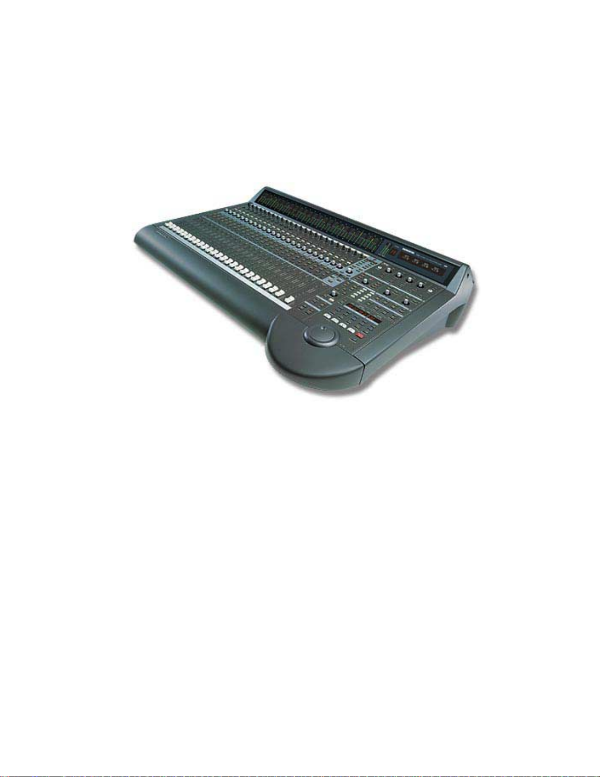
DIGITAL 8•BUS
OWNER’S MANUAL
Version 3.0
™
MACKIE’S 56-INPUT, 72-CHANNEL, FULLY AUTOMATED DIGITAL AUDIO MIXING CONSOLE
Page 2
SAFETY INSTRUCTIONS
1. Read Instructions — All the safety and operation instructions should be
read before this Mackie product is operated.
2. Retain Instructions — The safety and operating instructions should be
kept for future reference.
3. Heed Warnings — All warnings on this Mackie product and in these
operating instructions should be followed.
4. Follow Instructions — All operating and other instructions should be
followed.
5. Water and Moisture — This Mackie product should not be used near
water – for example, near a bathtub, washbowl, kitchen sink, laundry tub, in
a wet basement, near a swimming pool, swamp, or salivating St. Bernard
dog, etc.
6. Ventilation — This Mackie product should be situated so that its
location or position does not interfere with its proper ventilation. For
example, the Component should not be situated on a bed, sofa, rug, or
similar surface that may block any ventilation openings, or placed in a
built-in installation such as a bookcase or cabinet that may impede the
flow of air through ventilation openings.
7. Heat — This Mackie product should be situated away from heat sources
such as radiators or other devices which produce heat.
PORTABLE CART WARNING
Carts and stands - The
Component should be used
only with a cart or stand
that is recommended by
the manufacturer.
A Component and cart
combination should be
moved with care. Quick
stops, excessive force, and
uneven surfaces may cause
the Component and cart
combination to overturn.
8. Power Sources — This Mackie product should be connected to a power
supply only of the type described in these operating instructions or as marked
on this Mackie product.
9. Power Cord Protection — Power supply cords should be routed so that
they are not likely to be walked upon or pinched by items placed upon or
against them, paying particular attention to cords at plugs, convenience
receptacles, and the point where they exit this Mackie product.
10. Object and Liquid Entry — Care should be taken so that objects do not
fall into and liquids are not spilled into this Mackie product.
11. Damage Requiring Service — This Mackie product should be serviced
only by qualified service personnel when:
A. The power-supply cord or the plug has been damaged; or
B. Objects have fallen, or liquid has spilled into this Mackie
product; or
C. This Mackie product has been exposed to rain; or
D. This Mackie product does not appear to operate normally or
exhibits a marked change in performance; or
E. This Mackie product has been dropped, or its chassis
damaged.
12. Servicing — The user should not attempt to service this Mackie product
beyond those means described in this operating manual. All other servicing
should be referred to the Mackie Service Department.
13. Do not remove the cover on the console. It is permissible to remove the
outer cover on the Remote CPU to install accessory cards. Do not remove the
inner power supply cover.
14. To prevent electric shock, do not use this polarized plug with an
extension cord, receptacle, or other outlet unless the blades can be fully
inserted to prevent blade exposure.
Pour prévenir les chocs électriques ne pas utiliser cette fiche polariseé avec un
prolongateur, un prise de courant ou une autre sortie de courant, sauf si les
lames peuvent être insérées à fond sans laisser aucune pariie à découvert.
15. Grounding or Polarization — Precautions should be taken so that the
grounding or polarization means of this Mackie product is not defeated.
16. This apparatus does not exceed the Class A/Class B (whichever is
applicable) limits for radio noise emissions from digital apparatus as set out
in the radio interference regulations of the Canadian Department of
Communications.
ATTENTION —Le présent appareil numérique n’émet pas de bruits
radioélectriques dépassant las limites applicables aux appareils numériques de
class A/de class B (selon le cas) prescrites dans le règlement sur le brouillage
radioélectrique édicté par les ministere des communications du Canada.
FCC Information
NOTE: This equipment has been tested and found to comply
with the limits for a Class A digital device, pursuant to Part 15
of the FCC Rules. These limits are designed to provide
reasonable protection against harmful interference when the
equipment is operated in a commercial installation. This
equipment generates, uses, and can radiate radio frequency
energy and, if not installed and used in accordance with the
instruction manual, may cause harmful interference to radio
communications. Operation of this equipment in a residential
area is likely to cause harmful interference in which case the
user will be required to correct the interference at his own
expense.
WARNING — To reduce the risk of fire or electric shock, do
not expose this appliance to rain or moisture.
Page 3
Note: The following notice concerns the lithium battery located on the motherboard inside the Remote CPU.
CAUTION: DANGER OF EXPLOSION IF BATTERY IS INCORRECTLY REPLACED. REPLACE ONLY WITH THE SAME OR
EQUIVALENT TYPE RECOMMENDED BY THE MANUFACTURER. DISPOSE OF USED BATTERIES ACCORDING TO THE
MANUFACTURER’S INSTRUCTIONS.
ATTENTION: IL Y A DANGER D’EXPLOSION S’IL Y A REMPLACEMENT INCORRECT DE LA BATTERIE, REMPLACER
UNIQUEMENT AVEC UNE BATTERIE DU MEME TYPE OU D’UN TYPE ÉQUIVALENT RECOMMANDÉ PAR LE CONSTRUCTEUR.
METTRE AU REBUT LES BATTERIES USAGÉES CONFORMÉMENT AUX INSTRUCTIONS DU FABRICANT.
Statement of Conformity
Mackie Designs’ Digital 8•Bus has been tested and conforms to the following standards and directives of the
European Council:
73/23/EEC Low Voltage Directive with amendments
91/263/EEC, 89/392/EEC, and 89/336/EEC
89/336/EEC EMC Directive
IEC 950(1991)/EN60950:1992 Electrical Safety Requirements
EN55103-1 and EN55103-2 Residential (E1) and Commercial (E2) Environments
Part No. 820-256-00 Rev. A 5/01
©2001 Mackie Designs Inc., All Rights Reserved.
Printed in the U.S.A.
®
Page 4

Table of Contents
Preface.................................................................................................................................... 1
Chapter 1: Getting Ready ................................................................................................. 3
Introduction .................................................................................................................................................................... 4
About This Manual ............................................................................................................................................ 4
Let’s Get It Working.......................................................................................................................................... 4
Hooking Stuff Up ............................................................................................................................................... 4
A New Way of Thinking: Four Consoles in One!................................................................................... 7
Fader Bank Selection........................................................................................................................................ 8
Let’s Get Some Sound Happening ..............................................................................................................8
Figure 1-1 Completing the Microphone Signal Path ....................................................................................................... 9
Signal Routing Concept ................................................................................................................................ 10
Figure 1-2 Simple Microphone Connection/Basic Live Setup ................................................................................... 11
Figure 1-3 Setting Up to Track ................................................................................................................................................11
Figure 1-4 Basic Mixdown Setup .......................................................................................................................................... 12
Keep Close Track of These Concepts...................................................................................................... 12
Figure 1-5 Signal-Flow Diagram ............................................................................................................................................. 13
Figure 1-6 D8B Block Diagram ...............................................................................................................................................14
Figure 1-7 D8B Gain Structure Diagram ............................................................................................................................. 16
Specifications.................................................................................................................................................... 17
Physical Dimensions ....................................................................................................................................... 18
Updating Software .......................................................................................................................................... 19
Windows-based Computers..................................................................................................................................................19
Macintosh Computers ............................................................................................................................................................. 19
Summary ............................................................................................................................................................ 20
Chapter 2: Where Is it?..................................................................................................... 21
It’s Time to Locate Everything ...............................................................................................................................22
Rear Panel Description .............................................................................................................................................22
Channels 1–12 Inputs ...................................................................................................................................... 22
Channels 13–24 Inputs ...................................................................................................................................22
Card Cage Section...........................................................................................................................................22
Master Input/Output Section................................................................................................................... 23
AUX OUT Section ...........................................................................................................................................24
Remote CPU Description.........................................................................................................................................25
Data and Synchronization I/O ..................................................................................................................25
Connecting a Mouse, Keyboard and SVGA Monitor.........................................................................25
Other Connections .........................................................................................................................................25
Control Surface Functions ..................................................................................................................................... 26
Channel Strip Section ................................................................................................................................... 26
Master Section Description .................................................................................................................................. 28
Master Fader/Bank Select Section ......................................................................................................... 28
Master V-Pot Section.................................................................................................................................... 29
V-Pot Assign Section ......................................................................................................................................30
Figure 2-1 Aux Sends 1-8 (Default—Mackie Stereo Effects [MFX]) .......................................................................... 31
Fat Channel Section........................................................................................................................................ 32
D8B Manual • Table of Contents • page i
Page 5

Studio/Solo Section ...................................................................................................................................... 33
Phones/Cue Mix Section ............................................................................................................................. 34
Control Room Section ..................................................................................................................................34
Clipboard Section ........................................................................................................................................... 35
Master L-R/Shortcuts Section ..................................................................................................................36
Bus Assignment Section................................................................................................................................36
Automation Section ....................................................................................................................................... 36
Session Setup Section ...................................................................................................................................38
Transport Section ............................................................................................................................................39
Chapter 3: What’s On TV?................................................................................................ 41
Using the Graphic User Interface (GUI).............................................................................................................42
The Beauty of It….............................................................................................................................................42
The Master Strip .............................................................................................................................................. 47
Signal Path Flexibility .................................................................................................................................... 49
May I See A Menu Please......................................................................................................................................... 51
The File Menu ................................................................................................................................................... 51
The Edit Menu................................................................................................................................................... 53
The Channel Menu .......................................................................................................................................... 56
The Options Menu ..........................................................................................................................................59
Automation Sub-menu...........................................................................................................................................................60
Transport Sub-menu .................................................................................................................................................................61
The Plugins Menu ............................................................................................................................................ 61
The Windows Menu........................................................................................................................................ 63
The Desktop Window (Ctrl+D) ................................................................................................................. 64
The Setup Window (Ctrl+1) .................................................................................................................................................. 64
General ............................................................................................................................................................................... 64
MDS Network ................................................................................................................................................................... 64
Digital I/O ......................................................................................................................................................................... 65
Licensing ............................................................................................................................................................................. 66
Mix Options ...................................................................................................................................................................... 66
Locator-MMC ...................................................................................................................................................................68
FTP Server .......................................................................................................................................................................... 68
The Snapshot Window (Ctrl+2)........................................................................................................................................... 69
The Surround Window (Ctrl+3) ........................................................................................................................................... 70
The Locator Window (Ctrl+4)...............................................................................................................................................74
The Mix Editor Window (Ctrl+5) ........................................................................................................................................ 75
The Fat Channel Window (Ctrl+6) ..................................................................................................................................... 78
The Panning Window (Ctrl+7) .............................................................................................................................................. 82
The Faders Window (Ctrl+8) ................................................................................................................................................ 82
Event Automation Track (Ctrl+9) ........................................................................................................................................ 83
The History List Window (Ctrl+H)...................................................................................................................................... 84
The MIDI Map Window (Ctrl+ –)........................................................................................................................................ 85
Erase UFX Memory... ................................................................................................................................................................86
Upgrade UFX Cards.................................................................................................................................................................. 86
D8B Manual • Table of Contents • page ii
Page 6

Chapter 4: Applications .................................................................................................. 87
Setting Up for a Session .......................................................................................................................................... 88
Listening Environment.................................................................................................................................. 88
Channel Configuration/Planning............................................................................................................. 88
Power-up Procedure ...................................................................................................................................... 88
Figure 4-1 Power-up Procedure............................................................................................................................................ 88
Figure 4-2 Basic Connection for Multitrack Recording .............................................................................................. 89
Setup Window ................................................................................................................................................. 89
Installation and Connection of Optional I/O and Effects Cards................................................ 91
Installation of FX Cards................................................................................................................................ 92
Installation of I/O Cards .............................................................................................................................. 93
Checklist for Basic Operational Functionality ...................................................................................94
Connecting Analog Multitrack(s)............................................................................................................. 94
Connecting ADAT (Lightpipe) Multitrack(s) ........................................................................................ 94
Connecting TASCAM (TDIF) Multitrack(s) .............................................................................................95
Multitrack Recording .................................................................................................................................... 96
Multitrack Tracking Checklist .............................................................................................................................................. 97
Sample Tracking Setup ............................................................................................................................... 100
Mixdown Setup ..............................................................................................................................................102
Effects/Plug-ins ............................................................................................................................................ 104
Dynamics and EQ Applications .............................................................................................................. 106
MIDI and the D8B ..........................................................................................................................................107
Word Clock and the D8B – The Kitchen Sync .................................................................................. 108
Dither – To UV22 or Not to UV22: That Is the Question............................................................... 111
D8B–HDR24/96 Setup ................................................................................................................................112
Using the Digital 8•Bus with ADATs ........................................................................................................ 117
Connecting the Digital 8•Bus to a BRC and ADATs ..........................................................................118
Connecting the Digital 8•Bus to ADATs Using an External Sync Box.......................................120
Connecting the D8B to TASCAM MDMs ............................................................................................. 122
Digital Audio Workstation Setup ...........................................................................................................124
Live Sound/Live Recording Setup .........................................................................................................126
Post-Production Setup ................................................................................................................................128
Bouncing/Summing Using Bus Outs ..................................................................................................... 128
Using Basic Automation..............................................................................................................................129
Automation Procedural Checklists ........................................................................................................ 132
Appendices ........................................................................................................................ 133
Appendix A: Service................................................................................................................................................. 134
Appendix B: IVL Vocal Studio .............................................................................................................................. 136
About the IVL Vocal Studio....................................................................................................................... 136
The Interface ...................................................................................................................................................136
Operation–Harmony ...................................................................................................................................138
Operation–Pitch Correction .................................................................................................................... 142
Appendix C: Plug-in Configuration and Routing.......................................................................................... 144
Appendix D: Shortcuts............................................................................................................................................150
Appendix E: MIDI Implementation Guide ...................................................................................................... 153
Appendix F: Compatible Cables.......................................................................................................................... 154
Colophon ..................................................................................................................................................................... 163
Index.................................................................................................................................... 156
D8B Manual • Table of Contents • page iii
Page 7
Preface
he Mackie Digital 8•Bus is an amazing digital audio tool. Its flexibility, depth, and creative pizazz
provides the engineer/artist with nearly limitless freedom to produce top quality work.
T
The D8B Version 3.0 upgrade offers a host of new features that can make your mixes sound better and
speed your workflow. Here’s a list of the newest features of the Mackie OS Version 3.0.
WHAT'S NEW WITH 3.0
• Third-party plug-ins via the Mackie UFX card
• Enhanced dynamics
• Input keying and EQ filter
• Soft knee compression toggle
• 48-channel overview screen
• 999 levels of Undo
• Automation Cut, Copy, and Paste
• 24-bit Alt I/O
• Advanced Mix Editor features including:
New view-sizing arrows
°
Auto-loop SMPTE time code boxes
°
Loop-in/loop-out and Locate markers in the
°
time bar
Contextual right mouse click for track
°
parameters and time bars
Event Automation Track
°
• Enhanced Surround Sound mixing environment
with:
Depth of Center Control
°
Surround LFE Gain Control for each channel
°
Surround-corrected bus/track assignment
°
Surround Front-to-Rear Pan Control via
°
control surface or MIDI
Surround GUI update—new 72-channel
°
overview
• Triumphant Return of the Desktop—drag and
drop file management between File windows
• Enhanced, flexible MIDI I/O mapping for all
channel strip and master section parameters
• Assignable MIDI commands on transport (REW,
FF, STOP, PLAY, REC) and on the D8B master
control section
• Insert and patch point feature on channels—
source either plug-ins, 8 aux sends, 8 buses, or 72
channels (pre-DSP only)
• 24-bit plug-in inserts across Main L/R buses
• Time offset (delay) on each channel 1-48 with 255
samples
• Channel Layout assigns channel strips in various
orders
• Non-destructive Ungrouping
• Optional fader control of level to tape—direct out
signal follows the source fader channel
• Multiple direct outs per channel
• Snapshot Library
• Pre/Post assignment of each aux send on each
channel
• Improved BBT resolution and clocking accuracy
D8B Manual • Preface • page 1
Page 8
D8B Manual • Preface • page 2
Page 9

Chapter 1
Getting Ready
D8B Manual • Chapter 1 • page 3
Page 10
Introduction
his Guide reflects the newest and most
progressive features and options available
T
on the Mackie Digital 8•Bus. The D8B is
designed to grow with the audio industry. Each
software revision provides new features and
capabilities, updating your console and ensuring
that your investment remains current for many
years to come.
An increasing number of other manufacturers
have jumped on the D8B band wagon. Through
affiliations with companies like Apogee, TC
Electronics, Massenburg, dbx, and Antares,
Mackie Designs has provided an environment
where third-party plug-ins let you design the
perfect system for your needs—all within the
Digital 8•Bus architecture!
Let’s Get It Working
This is a step-by-step guide to get the Digital 8•Bus
working. We assume you’ve pulled everything out
of the box and are ready to start working.
First, you’ll need:
• 1 Stereo Power Amplifier
• 1 pair of Monitor Speakers (you can substitute a
pair of powered monitors for the power amplifier/
monitor speaker combo, or some stereo
headphones)
• Miscellaneous cables
• 1 cup of coffee (we think any native Seattle-based
beverage heightens the Mackie experience)
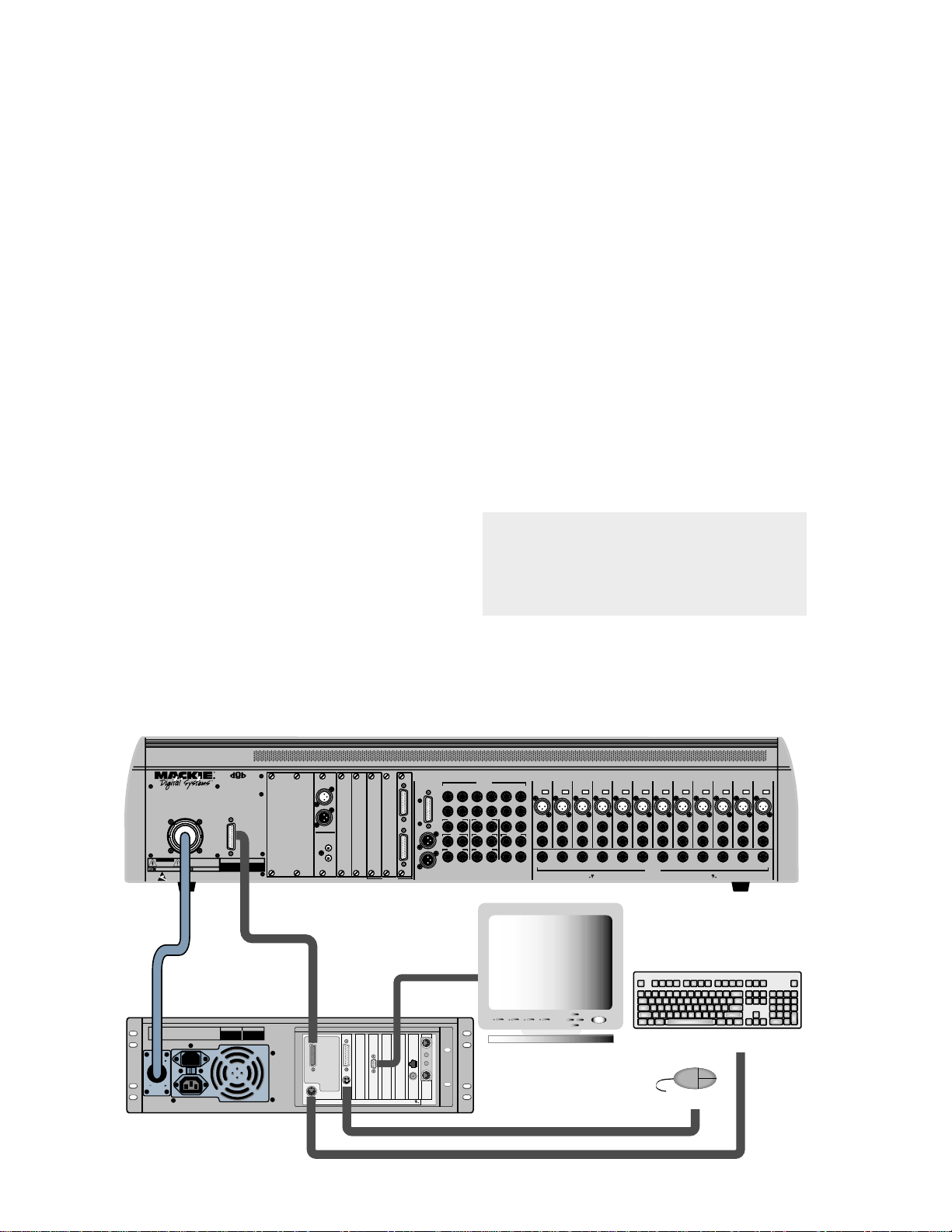
Hooking Stuff Up
First, connect the Remote CPU to the console.
About This Manual
This manual is the “let’s just do it” guide. Each
chapter covers an important consideration:
• Chapter 1 describes basic setup procedures with
an emphasis on achieving successful routing of an
audio source to your monitors.
• Chapter 2 briefly describes all surface controls.
• Chapter 3 describes the on-screen interface.
• Chapter 4 highlights some typical applications.
If you’d like to move ahead at light-speed, try
jumping directly to Chapter 4, using Chapters 2 and 3
as a reference. If you crave details, or if you’re new
to recording—especially digital recording—don’ t
forget to check out our website for more info at
www .mackie.com.
TAPE 1-8 TAPE 9-16 TAPE 17-24
1
IN
OUT
2
ANALOG I/O
BUS OUT 1-8
&
SURROUND OUT
L
ANALOG IN ANALOG OUT
R
MASTER OUT
WARNING:
SHUT OFF REMOTE POWER SUPPLY BEFORE CONNECTING
OR DISCONNECTING POWER SUPPLY CABLE FROM CONSOLE
POWER
SUPPLY
WARNING:
TO REDUCE THE RISK OF FIRE OR ELECTRIC SHOCK, DO NOT
CAUTION
EXPOSE THIS EQUIPMENT TO RAIN OR MOISTURE. DO NOT REMOVE COVER.
NO USER SERVICEABLE PARTS INSIDE. REFER SERVICING TO QUALIFIED PERSONNEL.
RISK OF ELECTRIC SHOCK
DO NOT OPEN
AVIS:
RISQUE DE CHOC ÉLECTRIQUE — NE PAS OUVRIR
UTILISE UN FUSIBLE DE RECHANGE DE MÊME TYPE.
REPLACE WITH THE SAME TYPE FUSE AND RATING.
DEBRANCHER AVANT DE REMPLACER LE FUSIBLE
DISCONNECT SUPPLY CORD BEFORE CHANGING FUSE
WARNING: SHUT OFF POWER TO UNIT BEFORE INSTALLING OR REMOVING CARDS!
56
INPUT72 CHANNEL
CONSOLE
DATA
SERIAL NUMBER
DIGITAL MIXER
A B C D
MANUFACTURING DATE
DIGITAL EFFECTS CARDS DIGITAL I/O SYNC ALT I/O TAPE IN/OUTS
DIGITAL I/O
DIGITAL I/O
IN
OUT
AES/EBU
S/PDIF
1. Connect the DC power cable between the Remote
CPU and the console. Rotate the outer sleeve of
the connector clockwise until the sleeve is snug
and finger-tight.
Caution: The Remote CPU weighs 42 pounds,
so we recommend that if you mount it in a
rack, you place it at the bottom of the rack
and provide additional support at the rear of
the unit.
LINE INPUTS
(BAL/UNBAL)
16
172418
23
MASTER OUT
LR
CR
MAIN
LR
CR
NEAR FIELD
LR
THIS DEVICE COMPLIES WITH PART 15 OF THE FCC RULES. OPERATION IS SUBJECT TO THE FOLLOWING TWO CONDITIONS:
1) THIS DEVICE MAY NOT CAUSE HARMFUL INTERFERENCE AND
2) THIS DEVICE MUST ACCEPT ANY INTERFERENCE RECEIVED THAT MAY CAUSE UNDESIRED OPERATION
PHONES 1
2 TRACK IN A
LR
2 TRACK IN B
LR
2 TRACK IN C
PUNCH I/O
LR
MACKIE DESIGNS
11
12
13
+48V
+48V
PH
PH
MIC MIC10MIC9MIC8MIC7MIC6MIC5MIC4MIC3MIC2MIC1MIC
19
2014211522
STUDIO OUT
LR
LINE IN
LINE IN
PHONES 2
INSERT
INSERT
TALKBACK
AUX11AUX
12
+48V
+48V
+48V
PH
PH
PH
LINE IN
LINE IN
LINE IN
INSERT
INSERT
INSERT
AUX8AUX9AUX
10
CONCEIVED, DESIGNED, AND MANUFACTURED BY MACKIE DESIGNS INC • WOODINVILLE • WA • USA • MADE IN USA • FABRIQUE AU USA • COPYRIGHT ©1997 •
THE FOLLOWING ARE TRADEMARKS OR REGISTERED TRADEMARKS OF MACKIE DESIGN INC.: "MACKIE", "DIGITAL SYSTEMS", D8B AND THE "RUNNING MAN" FIGURE •
+48V
+48V
+48V
PH
PH
PH
LINE IN
LINE IN
LINE IN
INSERT
INSERT
INSERT
7
AUX OUT
(BAL/UNBAL)
+48V
+48V
+48V
+48V
PH
PH
PH
PH
LINE IN
LINE IN
LINE IN
LINE IN
INSERT
INSERT
INSERT
INSERT
AUX1AUX2AUX3AUX4AUX5AUX6AUX
PATENTS PENDING
Data Cable
DC Power
Cable
MACKIE DESIGNS
THIS DEVICE COMPLIES WITH PART 15 OF THE FCC RULES. OPERATION IS SUBJECT TO
THE FOLLOWING TWO CONDITIONS: 1) THIS DEVICE MAY NOT CAUSE HARMFUL
INTERFERENCE AND 2) THIS DEVICE MUST ACCEPT ANY INTERFERENCE RECEIVED THAT
MAY CAUSE UNDESIRED OPERATION
120V
60Hz, 2.8A
120/230V
1.0/0.5A
SERIAL NUMBER MANUFACTURING DATE
CONSOLE DATA
KEYBOARD
D8B Manual • Chapter 1 • page 4
PARALLEL
MOUSE
CONCEIVED, DESIGNED, AND MANUFACTURED BY MACKIE DESIGNS INC • WOODINVILLE • WA • USA • MADE IN USA • FABRIQUE AU USA • COPYRIGHT ©1997 •
THE FOLLOWING ARE TRADEMARKS OR REGISTERED TRADEMARKS OF MACKIE DESIGN INC.: "MACKIE", "DIGITAL SYSTEMS", D8B AND THE "RUNNING MAN" FIGURE •
Multi-Sync Video Monitor
PC-Compatible Keyboard
PS/2 Mouse
Page 11
CPU
PARALLEL
MIDI
CONSOLE DATA
MOUSE
Mouse
KEYBOARD
Keyboard
CONCEIVED, DESIGNED, AND MANUFACTURED BY MACKIE DESIGNS INC • WOODINVILLE • WA • USA • MADE IN USA • FABRIQUE AU USA • COPYRIGHT ©1997 •
THE FOLLOWING ARE TRADEMARKS OR REGISTERED TRADEMARKS OF MACKIE DESIGN INC.: "MACKIE", "DIGITAL SYSTEMS", D8B AND THE "RUNNING MAN" FIGURE •
2. Connect the data cable between the Remote CPU
and the console. Rotate the thumbscrews on each
connector clockwise until they are finger tight.
3. Make sure the POWER switch on the Remote
CPU is off.
4. Connect the detachable linecord to the Remote
CPU. Shortly, we’ll connect to AC power .
Ethernet
Video
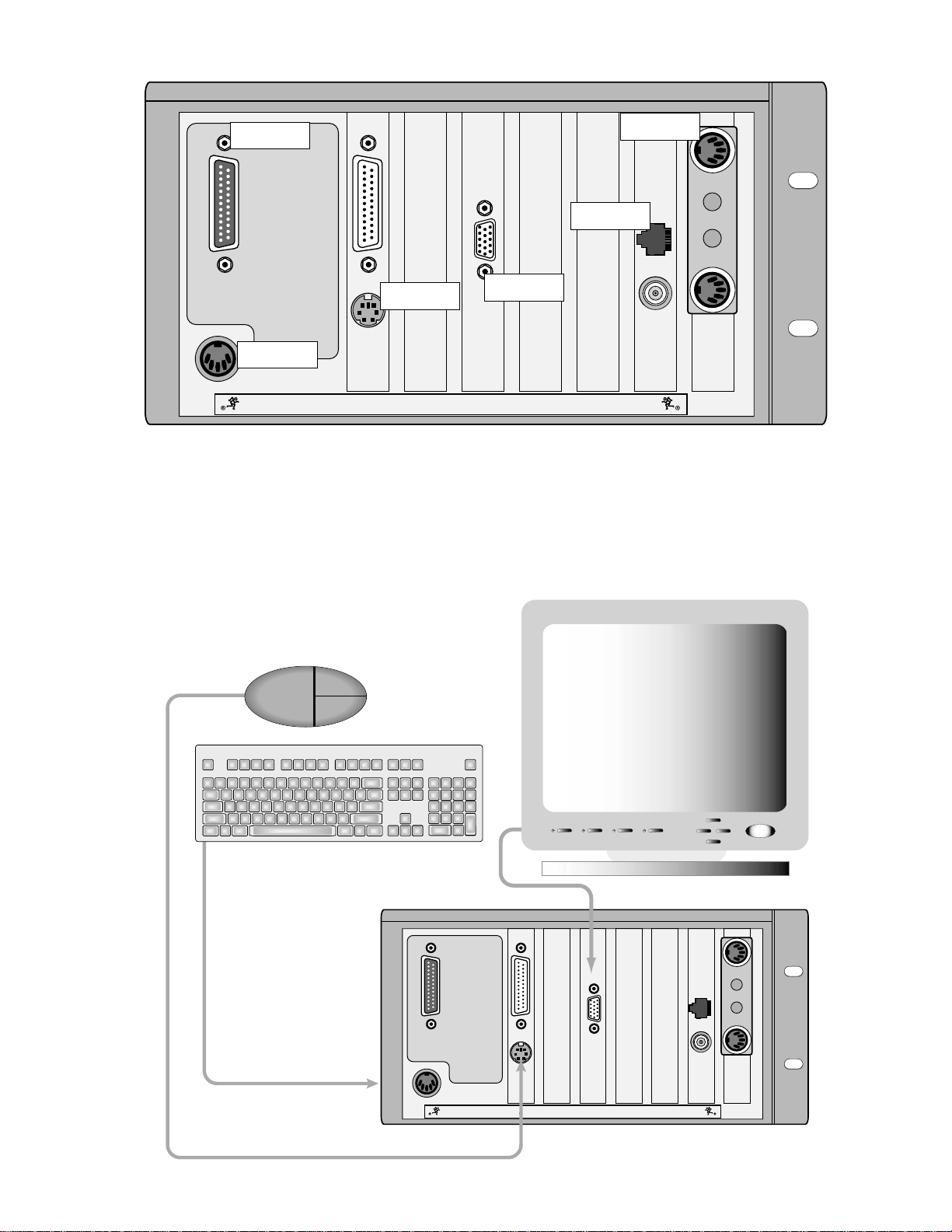
Next, connect the keyboard, mouse,
and video monitor.
These connections are optional, but we strongly
recommend using them to get the most from your
new Digital 8•Bus console.
PARALLEL
CONSOLE DATA
MOUSE
KEYBOARD
CONCEIVED, DESIGNED, AND MANUFACTURED BY MACKIE DESIGNS INC • WOODINVILLE • WA • USA • MADE IN USA • FABRIQUE AU USA • COPYRIGHT ©1997 •
THE FOLLOWING ARE TRADEMARKS OR REGISTERED TRADEMARKS OF MACKIE DESIGN INC.: "MACKIE", "DIGITAL SYSTEMS", D8B AND THE "RUNNING MAN" FIGURE •
D8B Manual • Chapter 1 • page 5
Page 12
1. Plug a PC-compatible keyboard into the KEY BOARD port on the back of the Remote CPU.
2. Plug a PS/2 compatible mouse into the MOUSE
port on the back of the Remote CPU.
3. Plug an SVGA video monitor into the VIDEO port
on the back of the Remote CPU.
Note: We highly recommend the use of a multisync
monitor; however , if one is unavailable you must use a
monitor capable of at least a 72Hz scan rate. We
recommend using a 17-inch or larger monitor for best
results.
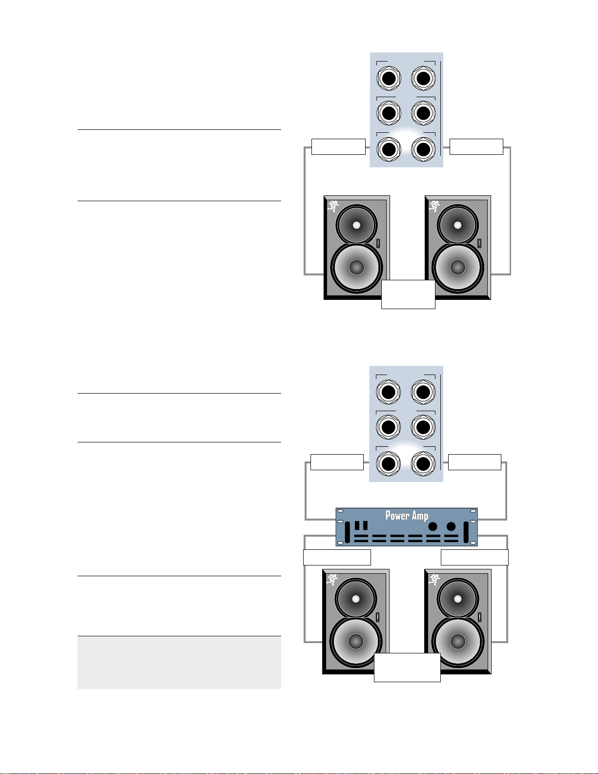
Now connect the audio inputs and outputs
to the console.
1. Connect the CR NEAR FIELD or CR MAIN
outputs on the back of the Digital 8•Bus to the
line inputs of the power amplifier . These outputs
are wired balanced when using a tip-ring-sleeve
connector or unbalanced when using a tip-sleeve
connector . Use instrument/line-level cable for this
connection.
2. Connect monitor speakers to the output of the
power amplifier using speaker cable. Always use
high quality wire. The sound you hear will be
more reliable and accurate.
MASTER OUT
LR
CR
MAIN
LR
CR
NEAR FIELD
LR
Line Cable Line CableLine Cable Line Cable
Powered
Monitors
Connect directly from CR NEARFIELD or CR MAIN
to powered reference monitors using line-level cable.
MASTER OUT
LR
Note: If you’re using powered monitors, connect the
Left and Right CR NEAR FIELD outputs directly to
the line inputs on the powered monitors.
Optional Refreshments
Have a sip of java and a biscotti.
Details
Make sure the POWER switch on the Remote CPU
is off. Now plug the linecord into an AC outlet
properly configured for your model. Leave the
POWER switch off while connecting the
peripheral equipment to the console.
Note: The Remote CPU should be treated as you would
any computer. We recommend that you use a UPS
(Uninterruptible Power Supply) and a surge protector
on the AC line.
Caution: Never connect or disconnect anything
except microphone or line-level inputs while
the console is powered up.
CR
MAIN
LR
CR
NEAR FIELD
LR
Line Cable Line Cable
Speaker Cable Speaker Cable
Non-powered
Monitors
Connect from D8B outputs to power amp using line
cable, then from amp to non-powered speakers using
speaker cable.
D8B Manual • Chapter 1 • page 6
Page 13
T urn on the power switch on the front panel of the
Remote CPU, then turn on the power to all your
peripheral equipment. The Digital 8•Bus takes a few
moments to load the Mackie Real Time OS
(Operating System) and initialize the DSPs. When
the Vacuum Fluorescent Display (VFD) in the
onboard Fat Channel Section indicates EQ settings
for channel 1, the console is ready to use.
These buttons let you access four completely
different sets of controls, referred to as Fader Banks.
Even though only one Fader Bank is accessible at a
time, all four are fully functional at all times. Use of
a computer monitor provides on-screen control of
two fader banks at a time.
Fast Track Power-Up
1. Switch D8B power on.
2. V erify that SPEAKER LEVEL
V-Pot is turned all the way down.
F
3. Switch on all peripherals
(processors, recorders,
T
AST
RACK
interfaces, etc.).
4. Switch on monitor amplifier or powered
monitors.
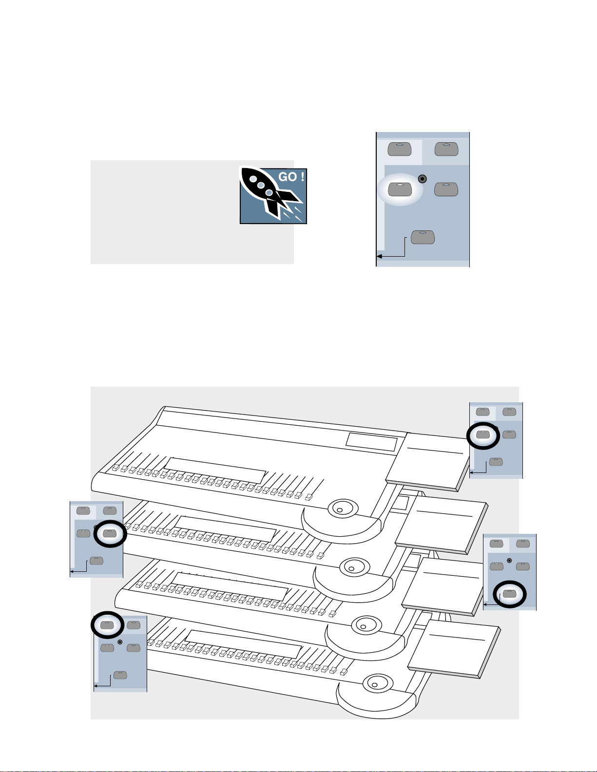
A New Way of Thinking:
Four Consoles in One!
With the Digital 8•Bus, what you get is way more
than what you see at first glance. Directly above
the Master L/R fader, locate four buttons labeled
MIC/LINE, TAPE IN, EFFECTS, and MASTERS.
C
h
a
n
n
e
ls 1
-2
4
MASTERS
1-24
MIC/LINE
(TRACK) (MONITOR)
BANK SELECT
SHIFT
25-48
TAPE IN
49-72
EFFECTS
Now that you’ve got the Digital 8•Bus
powered up, try the different fader banks.
• Press the MIC/LINE button and set up a
random set of fader levels.
• Press the TAPE IN button and set up a
completely different set of fader levels.
• Do the same for EFFECTS and MASTER.
MASTERS
1-24
MIC/LINE
Fader Bank 1
Channels 1-24
Mic/Line
Tracking
(TRACK) (MONITOR)
49-72
EFFECTS
BANK SELECT
SHIFT
25-48
TAPE IN
MASTERS
1-24
MIC/LINE
TAPE IN
(TRACK) (MONITOR)
49-72
EFFECTS
BANK SELECT
MASTERS
1-24
MIC/LINE
(TRACK) (MONITOR)
SHIFT
25-48
49-72
EFFECTS
BANK SELECT
SHIFT
25-48
TAPE IN
Fader Bank 2
Channels 25-48
C
h
a
n
n
e
ls 2
5
-4
8
F
X
R
e
tu
rn
1
-1
6
; A
L
T
R
e
tu
rn
1
-8
G
ro
u
p
s 1
-8
; M
ID
I 1
-8
; B
u
s 1
-8
Monitor/Tape In
Mixdown
Fader Bank 3
Channels 49-72
FX Return 1-16
ALT Return 1-8
Fader Bank 4
Virtual Groups 1-8
MIDI Controllers 1-8
Bus 1-8 Masters
MASTERS
1-24
MIC/LINE
TAPE IN
(TRACK) (MONITOR)
49-72
EFFECTS
BANK SELECT
SHIFT
25-48
D8B Manual • Chapter 1 • page 7
Page 14

As you switch back and forth between all four
fader banks, the faders will move to their respective settings for each bank. You’ll find that this
becomes your most popular demonstration. Your
friends will love it; your spouse will love it; your
pet will be mildly amused.
This exercise demonstrates a process that
will become second nature as you increase your
skills on the Digital 8•Bus. The layered approach
to digital mixing is actually very convenient, while
at the same time providing tons of features in a
compact package. This mixer contains more
flexibility and features than most consoles taking
up 12 or more feet of desk space and costing up to
50 times more!
Fader Bank Selection
• MIC/LINE button = Fader Bank 1
(Channels 1–24)
• T APE IN button = Fader Bank 2 (Channels 25–48)
• EFFECTS button = Fader Bank 3 (Channels 49–
72: Internal Effects Returns, FX 1–16, and ALT
RET urns 1–8)
• MASTERS button = Fader Bank 4 (Virtual Groups
1–8, MIDI Controllers 1–8, Bus Masters 1–8)
This architecture provides a total of 56 inputs,
with Fader Banks 1 and 2 providing 48 inputs, and
the 8 ALT Returns in Fader Bank 3 providing
another 8 inputs.
One of the primary applications the Digital 8•Bus
was designed for is multitrack recording (generally
up to 24 tracks). This involves tracking and
monitoring, bouncing, overdubbing, and mixdown.
You can think of Fader Bank 1 and Fader Bank 2 as
two separate mixing consoles, where Fader Bank 1
is used for tracking and Fader Bank 2 is used for
monitoring and mixdown.
T wo 24-track machines can easily be connected
to the D8B for mixdown: one into the Fader Bank 1
line inputs, and the other into the Fader Bank 2
(T ape) I/O cards. This setup provides an amazing
amount of control through automation, routing, and
DSP!
Note: Although the D8B is perfectly set up for 24-track
recording, it’ s possible to route channels to 46 outputs,
all at the same time: 24 direct outputs (3 cards),
8 buses (Alt I/O), 2 main stereo outputs, and 12 auxes.
Let’s Get Some Sound Happening
• Mixer Power On.
• Monitors connected and on.
• Microphone or Instrument
plugged into Channel One.
• Phantom Power button
pushed in if required.
• Fader Bank 1 (MIC/LINE selected).
• Press the MIC button down when using a
microphone; leave it up for an instrument.
• While sound source is active, adjust TRIM for
a reading around –15 on the channel 1 meter .
• Select L–R in the ASSIGNMENT section, then
verify that the ASSIGN button on Channel One
lights up green.
• In the CONTROL ROOM section, select
MASTER L–R.
• Select the desired SPEAKERS in the
CONTROL ROOM section.
• Set the SPEAKER LEVEL V -pot to about
11:00.
• Turn the MASTER L/R fader up to unity.
• Slowly raise the level of the Channel One fader
until you hear sound.
• The Master L/R meters should display levels.
• Rejoice in the sense of accomplishment while
listening to crystal-clear audio.
Refer to Figure 1-1 for the Fast T rack Graphic
description of this procedure.
Details
1. Especially for digital connections, it’ s important
that the Digital 8•Bus is powered up first. This
procedure helps establish the mixer as a primary
source in the digital sync scheme.
2. Be sure you’ve noted which output is connected to
the monitor system(s) and be sure they’re
powered up.
3. Be sure the microphone or instrument is plugged
into Channel 1 and that Fader Bank 1 (MIC/LINE) is
selected. It doesn’ t take long to get used to
selecting the fader bank you really need to access;
however, at first make a conscious effort to
include this step in your routine.
4. Be sure the button below the gain trim labeled
MIC is pressed down for a microphone or is in the
up position for an instrument When working fast
this button is sometimes overlooked. If it’s in the
wrong position there won’ t be any signal to play
with. That’s bad. Get in the habit of following the
signal from the source to the destination—step by
step. If you don’ t leave any steps out you’ll be
successful every time.
F
T
AST
RACK
D8B Manual • Chapter 1 • page 8
Page 15
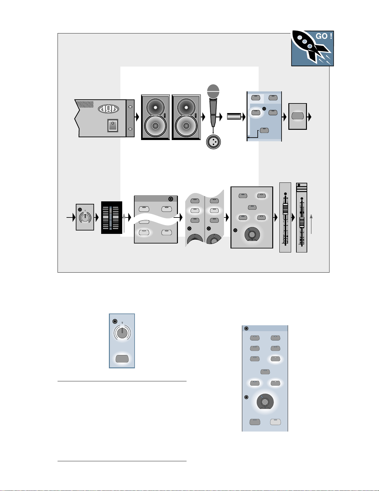
Figure 1-1 Completing the Microphone Signal Path
Follow this graphic map to quickly complete a signal path using a microphone to capture the
sound source..
Mic into
Power On
Speakers On and
Connected to Mixer
Mic Input
Phantom
power
Select Fader
Bank 1
MASTERS
MIC/LINE
SHIFT
1-24
25-48
TAPE IN
(TRACK) (MONITOR)
49-72
EFFECTS
BANK SELECT
F
AST
T
RACK
Mic Button
Down
MIC
Trim Up Until
Channel Meter Reads
Around –15 dBFS
TRIM
I
L
M
060
-
20dB +40dB
1
N
E
C
I
1
25
OL
2
4
7
10
15
20
25
30
40
50
60
Select L/R in ASSIGNMENT, then
Verify Assign on Channel Strip
ASSIGNMENT
ASSIGN ASSIGN
ASSIGN
BUS 7
ASSIGN ASSIGN
L-R
BUS 2
BUS 8
ROUTE TO
TAPE
5. Start with gain TRIM down. While talking into the
mic or playing the instrument, turn it up until the
level stays around –15 to –10 on the channel one
meter .
TRIM
N
E
I
L
C
I
M
060
+40dB
-
20dB
1
MIC
REC/RDY REC/RDY
ASSIGN
WRITE
ASSIGN
WRITE
Verify
MASTER L/R
2 TRACK C
MONO
OR
NEAR FIELD
SPEAKER S
SPEAKER LEVEL
Select Monitors/Set
V-pot Around 11:00
MASTER
L-R
MAIN
Master Fader
at Unity
MASTER
L/R
dB
10
5
U
5
10
20
30
40
50
60
Raise Channel
Level to Hear
6. In the CONTROL ROOM section, press the
MASTER L–R button so the yellow light comes
on. Assigning this button sends whatever is
coming from the MASTER L/R fader to the
selected speakers.
CONTROL ROOM
2 TRACK A
2 TRACK B
2 TRACK C
DIGITAL IN 1
DIGITAL IN 2
MASTER
L-R
GROUP 1
dB
10
5
U
5
10
20
30
40
50
60
FX 1
1
25
Note: The TRIM and MIC button status are two of the
only controls that are not written into automation or
snapshot data. That’ s a disadvantage of analog circuitry ,
but these controls are necessary. Running a strip of
white safe-release tape across the top label strip allows
for careful recording of each channel’ s TRIM level and
MIC button status. This kind of tape can be removed
and folded for storage with session documentation,
guaranteeing accurate settings whenever you need to
restore the mix.
MONO
OR
NEAR FIELD
SPEAKER LEVEL
DIM
SPEAKE RS
MAIN
TALK B AC K
D8B Manual • Chapter 1 • page 9
Page 16
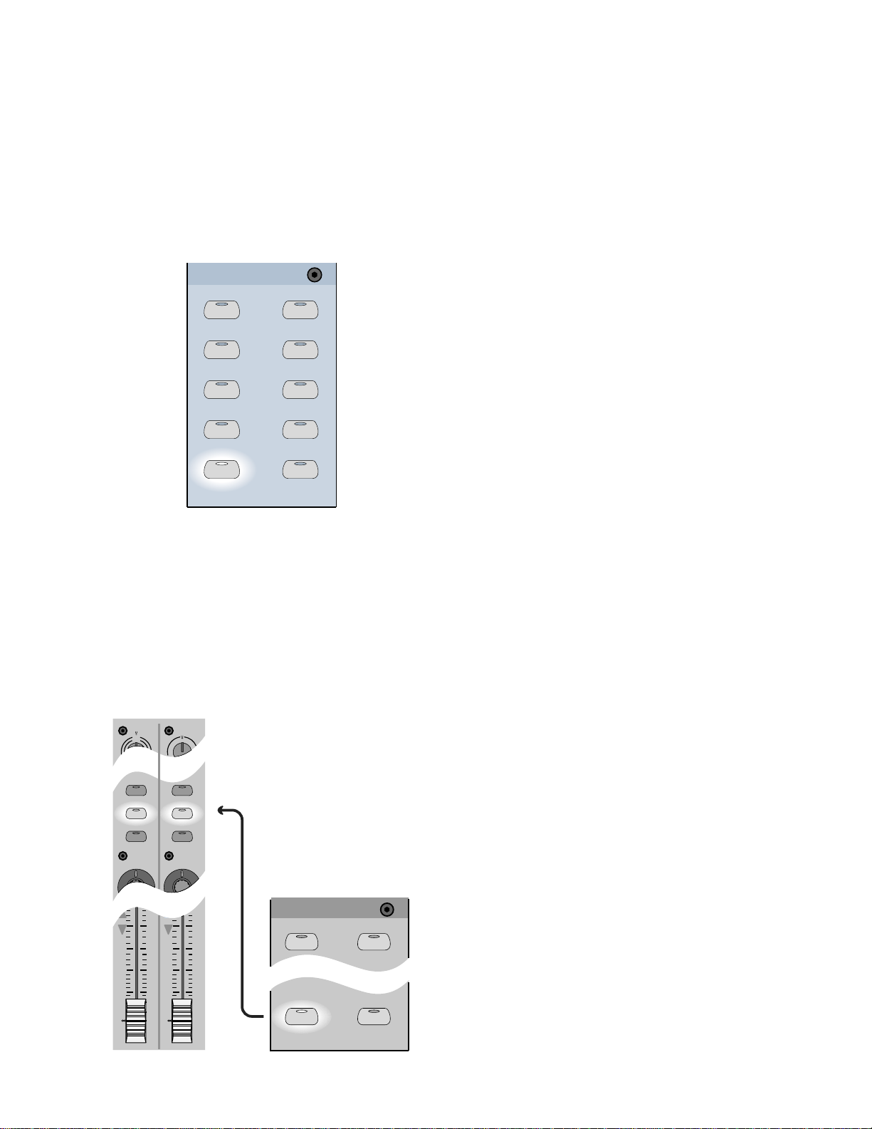
7. In the ASSIGNMENT section, verify that when
L–R is selected (green light on) the ASSIGN
button in Channel One lights up green. This is
basic bus assignment procedure. Anything you
want to come out the MASTER L–R bus must
light up on the assign button of each desired
channel. In similar fashion, any channel that
needs to be assigned to Bus 1 must have the
channel assign button lit when Bus 1 is selected
in the ASSIGNMENT section.
ASSIGNMENT
ASSIGN ASSIGN
BUS 1
ASSIGN ASSIGN
BUS 3 BUS 4
ASSIGN ASSIGN
BUS 5
ASSIGN ASSIGN
BUS 7
ASSIGN ASSIGN
L-R
BUS 2
BUS 6
BUS 8
ROUTE TO
TAPE
Signal Routing Concept
The Digital 8•Bus, with its multilayer technology,
literally performs the work of at least four consoles.
T o help organize the various connections, visualize
each bank as a new console. The “V” or “Multi-V”
diagrams that follow provide a simple and accurate
mental image of the signal flow and/or processing
while you put the Digital 8•Bus through its paces.
Figure 1-2 demonstrates a simple connection
scheme utilizing a microphone that’s routed though
the D8B to the monitor system.
Figure 1-3 demonstrates a tracking setup. Notice
how the graphic representation of two separate fader
banks supports the mental image of the D8B concept:
sound source into the MIC/LINE bank, then routed
to the multitrack, then back into the TAPE IN bank.
Figure 1-4 adds a mixdown recorder . The beauty
of this concept lies in its flexibility. Start at the
beginning, middle, or end of the signal path—it
doesn’ t matter. When the routing concept is
understood, the process is simple.
8. Be sure the SPEAKER button is lit that
corresponds to your monitor system
connection—that the yellow light shows on
NEAR FIELD or MAIN.
9. T urn the SPEAKER LEVEL V-pot up to about
11:00.
10. Turn the MASTER L/R fader up to unity.
11. Slowly raise the level of the Channel One fader
until you hear sound.
TRIM TRIM
N
E
I
L
12
REC/RDY REC/RDY
ASSIGN
WRITE
10
20
30
40
50
60
ASSIGN
WRITE
ASSIGNMENT
10
20
30
40
50
60
ASSIGN ASSIGN
ASSIGN
BUS 7
ASSIGN ASSIGN
L-R
BUS 2
BUS 8
ROUTE TO
TAPE
D8B Manual • Chapter 1 • page 10
Page 17
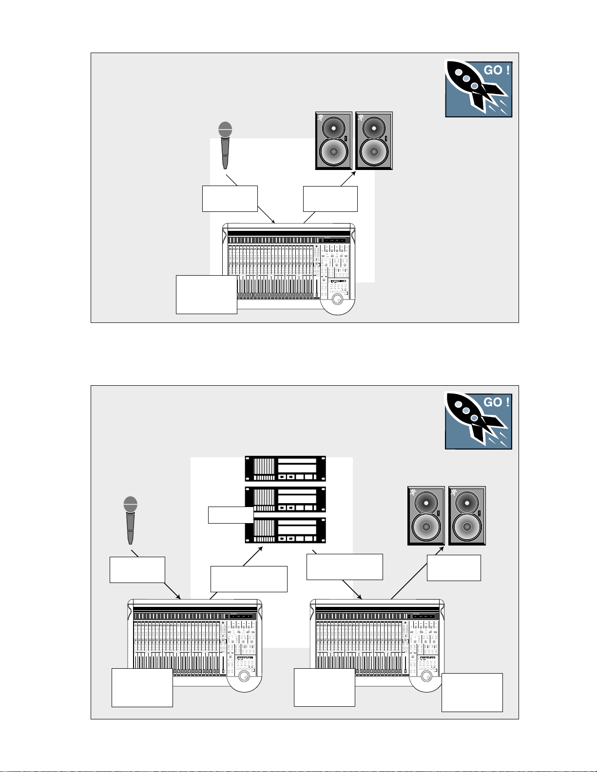
Figure 1-2 Simple Microphone Connection/Basic Live Setup
This setup illustrates the most fundamental use of the D8B. A very basic live setting might
require only this limited level of complexity.
F
T
RACK
AST
Channel 1–24
Mic/Line In
Channels 1–24
Tracking Mixer
Fader Bank 1
Monitor Outs
to Speakers
Figure 1-3 Setting Up to Track
The graphic below highlights the simplicity of the D8B tracking procedure. Once levels to
tape are set, using the Channel Trim controls, it’s typically best to monitor the mix from
the TAPE IN Fader Bank throughout tracking.
F
T
RACK
AST
Channel 1–24
Mic/Line In
Channels 1–24
Tracking Mixer
Fader Bank 1
Multitrack
Tape or Bus Outs to
Multitrack Inputs
From Tape to Channel
25–48 Inputs
Channels 25–48
Tape Returns
Fader Bank 2
Monitor Outs
to Speakers
Channel Assign-
ments Routed to
L/R Mix
D8B Manual • Chapter 1 • page 11
Page 18
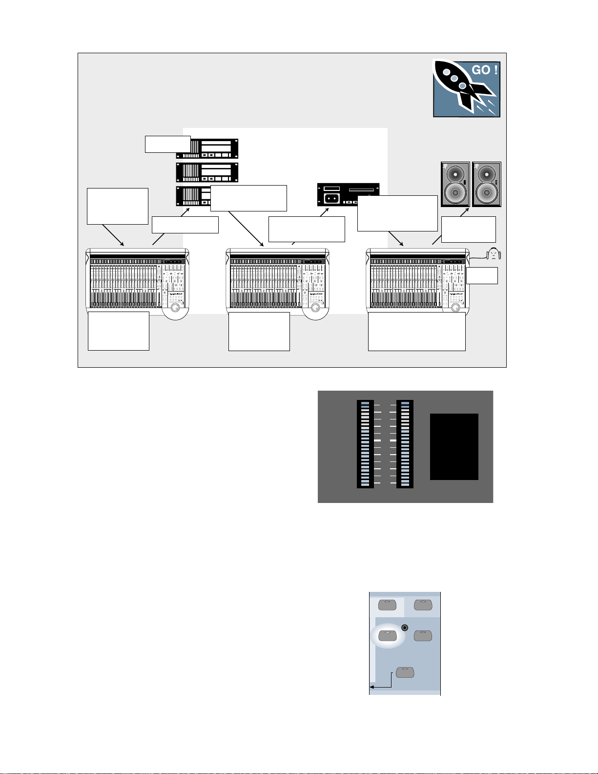
Figure 1-4 Basic Mixdown Setup
This is a basic mixdown setup. Live Mic/Line input source might be used for any audio
source: live vocals, instruments, or effects returns.
Multitrack
F
T
RACK
AST
Outboard Effects,
MIDI Gear, Live
Room Mics, etc.
Channels 1–24
Tracking Mixer
Fader Bank 1
Tape or Bus Outs
From Tape to Channel
25–48 Inputs
Channels 25–48
Monitor Tape
Fader Bank 2
Use this diagram for troubleshooting!
Signal Flow
The previous diagrams help create an accurate
mental image of how the D8B functions. The signal
flow diagram in Figure 1-5 (on the next page) looks
more closely at the actual path the signal takes from
a point of origin to a chosen destination. This is a
simplified flow-diagram designed to provide a “bird’seye” view . Follow the signal from left to right. Notice
the first thing the signal encounters, after the analog
inputs (including the analog trim), is the analog-todigital converter . The audio remains in the digital
domain from that point until it finally converts back
to analog at the main outputs, bus outputs, and
external aux sends. Simply follow the arrows to
discover the path—you never know where you might
end up. For a more detailed block diagram of the
D8B signal path refer to Figure 1-6.
From Mix Playback to
2-Track Input (Analog
From Master Out to
or Digital)
Mixdown Recorder
Monitor Mixdown Machine
at CONTROL ROOM in the
Master Section
OL
2
4
7
10
15
20
25
30
35
40
50
LEFT RIGHT
CHANNEL
33
2. Be sure you verify the Bank Selection whenever
you need to make a change. At first it’s easy to
forget to check the Fader Bank status. However,
once you’ve adjusted to the layered consoles,
maneuvering throughout the entire console will
become second nature.
Monitor Outs
to Speakers
Phones
Keep Close Track of These Concepts
1. The Channel Select Display, next to the Master
L/R meters, always displays the currently
selected channel number no matter which Fader
Bank is selected. If an adjustment is required in
the Fat Channel, verify that the channel you
intend to adjust is displayed here.
D8B Manual • Chapter 1 • page 12
49-72
EFFECTS
BANK SELECT
SHIFT
25-48
TAPE IN
MASTERS
1-24
MIC/LINE
(TRACK) (MONITOR)
Page 19
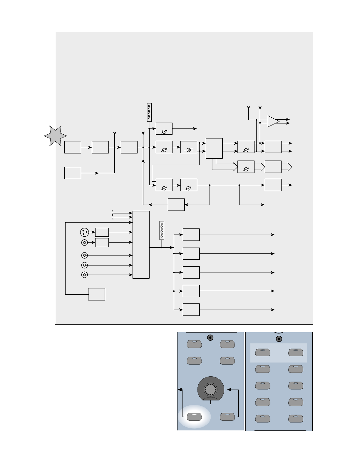
Figure 1-5 Signal-Flow Diagram
AUX 7
AUX 8
AUX 5
AUX 6
AUX 1
AUX 3
AUX 2
AUX 4
LEVEL TO TAPE
DIGITAL TRIM
1-24 1-48
Simply begin at the far left star and follow the route the signal must take to reach the master output.
DSP includes all dynamics, equalization, and phase controls.
Main Inserts
Tracking/Routing
Pre-DSP
Insert
Post-DSP
Insert
Channel
Meter
Level to
Tape
To Tape Outputs
R L
AES/EBU Out
S/PDIF Out
Analog
Inputs
CH 1-48
Optional
Digital Tape
I/O Card
Monitoring
AES/EBU
S/PDIF
2 TRK A
2 TRK B
2 TRK C
Analog to
Digital
Converter
Auxes 9/10
Auxes 11/12
DAC
DAC
From
L/R Out
DSP
(EQ, Comp,
Gate, etc.)
Control
Room
Select
Ch. 49 54
Pre
Channel
Aux Send
FX
Returns
Fader
Level
Internal
Main L/R
Meter
FX
Channel
Pan
Post
Master Aux
Send Level
Near Field
Speaker
Level
Main
Speaker
Level
Studio
Level
Cue Mix 1
Level
Cue Mix 2
Level
Sends 1 – 8
Bus
Assign
Bus 1-8
L
Master L/R
Fader
R
Bus Master
Digital to
Analog
Converter
Digital to
Analog
Converter
Digital to
Analog
Converter
Lake Sammamish
6 miles
CR
Nearfield
Out
CR
Main
Out
Studio
Out
Phones 1
Out
Phones 2
Out
Main
Out
Bus 1-8
Outputs
Aux
Sends
3. When using the V-Pot to adjust a parameter ,
make sure it’s assigned to make the change you
need. Since the V -Pot is a multifunction
control, it’s easy to assume it’s doing the job you
want when it might be changing a completely
different setting. Intentionally check the status
of the V-Pot before making a change.
AUX 9-10
PAN
PAN
MASTER
AUX 11
-
12
PAN
SOLO
D8B Manual • Chapter 1 • page 13
Page 20
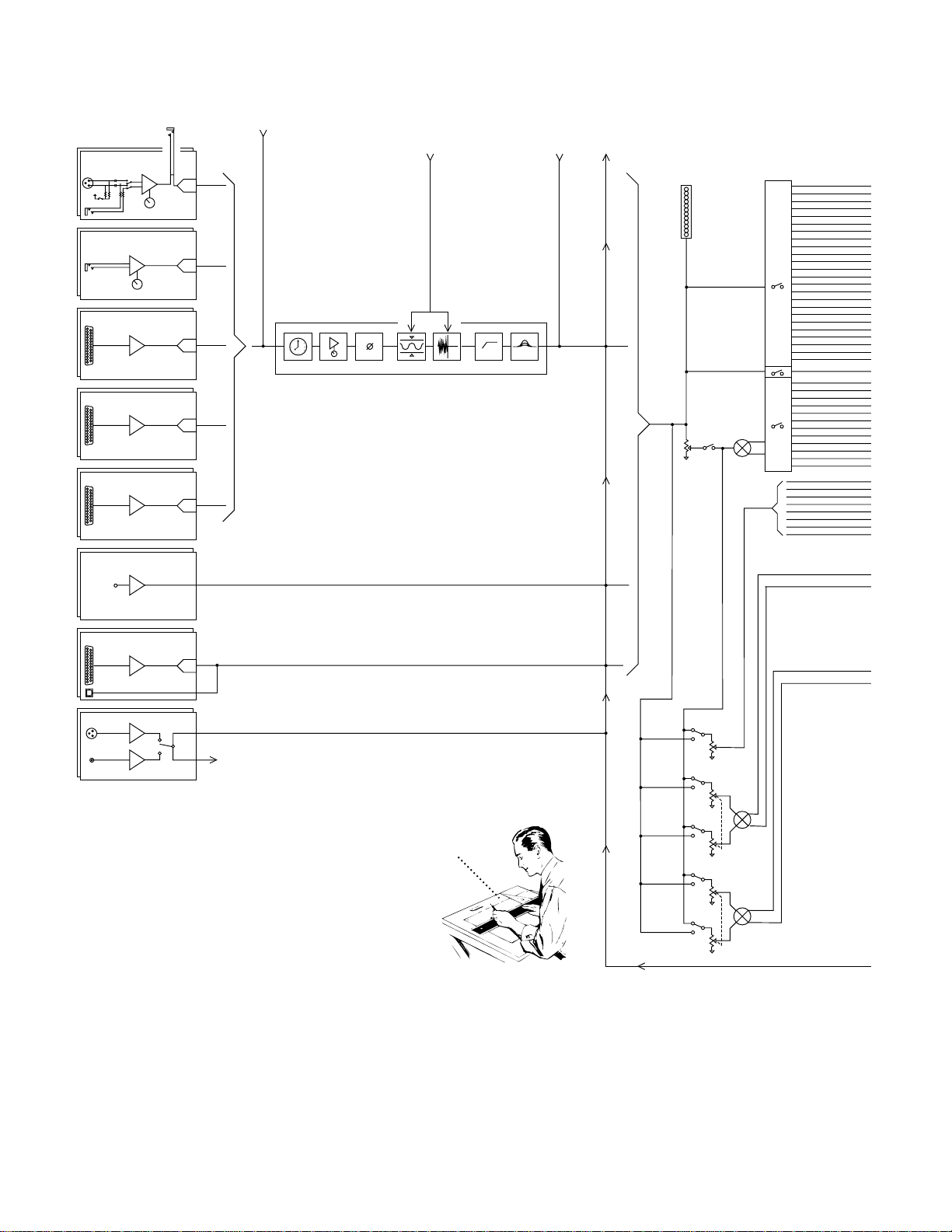
MIC/LINE 1 (through 12)
MIC IN
MIC/LINE
48V
LINE IN
ANALOG STEREO
INSERT/RETURN
TRIM
A to D
PRE-DSP
INSERT
(CHANNEL TAP
AND PLUG-INS)
KEY INPUT
Default: Itself (the channel)
OR:
CHANNEL TAP
BUS TAP
AUX TAP
2-TRACK DIGITAL INPUT
POST-DSP
INSERT
(PLUG-INS
ONLY)
CHANNEL
TAP
METER
LINE 13 (through 24)
LINE IN
FROM TAPE 25 (through 32)
FROM TAPE 33 (through 40)
FROM TAPE 41 (through 48)
TRIM
Analog 8 channel TAPE CARD
(optional)
Analog 8 channel TAPE CARD
(optional)
Analog 8 channel TAPE CARD
(optional)
FX card A. inputs 49–52
Inputs 53–64
(optional — B, C, D cards)
ALT I/O CARD 65-72 (optional)
TDIF/ADAT 8 channel format
(optional)
A to D
A to D
A to D
A to D
A to D
DELAY DIG. TRIM
COMPEQGATE
PHASE HI PASS
FADER
DIRECT ASSIGN
TO TAPE OUT
PFL SOLO
MUTE
PAN
AES/EBU & S/PDIF STEREO INPUT
TO CONTROL ROOM
SELECT
Digital 8•Bus
Block Diagram
4 / 12 / 2001”
Figure 1-6 D8B Block Diagram
This diagram provides a detailed view of the D8B signal path.
“Mackie
PRE/
POST
AUX
LEVEL
AUX
LEVEL
AUX
LEVEL
AUX
LEVEL
AUX 1–8
AUX
PAN
AUX
PAN
D8B Manual • Chapter 1 • page 14
Page 21
AUX 11/12
T
T
T
AUX 9/10
TAPE 1–8
TAPE 9–16
TAPE 17–24
PFL SOLO
SOLO L
SOLO R
MAIN LEFT
MAIN RIGHT
BUSES 1–8
AUX SEND 1–8
AUX SEND 9
AUX SEND 10
AUX SEND 11
AUX SEND 12
AUX
TAP
LEVEL
D / A
FX CARDS
AUX 1 (of 8)
MASTER
AUX SOLO 1 (of 8)
D8B Manual • Chapter 1 • page 15
TO FX METER SELECT
LEVEL TO TAPE
LEVEL TO TAPE
LEVEL TO TAPE
BUS LEVEL
MUTE
D / A
TAPE 1–8
TAPE 9–16
TAPE 17–24
PFL SOLO
MIXDOWN
SOLO
SOLO L
SOLO R
MAIN LEFT
MAIN RIGHT
BUSES 1–8
AUX SEND 1–8
AUX SEND 9
AUX SEND 10
AUX SEND 11
AUX SEND 12
ONLY SOLOED CHANNELS
MIXDOWN SOLO SENDS
TO MAIN L/R BUS
MASTER
FADER
MAIN INSERT R (L)
D8B OUTPUT SECTION
X2 LEFT AND (RIGHT)
D / A
AUX 9/10 MASTER
(
)
AUX SOLO 9 (10)
LEVEL
D / A
SOLO
AFL
PFL
PFL/AFL/MIXDOWN
D / A
( )
A
2 TRK IN
2 TRK A
MASTER L-R
DIG IN 2
CONTROL ROOM
SELECT
LEVEL
AES/EBU IN
DIG IN 1
FROM
D / A
S/PDIF IN
FROM
D / A
(R)
TALKBACK TO STUDIO
TB LEVEL
TALKBACK
D / A
AUX 11/12 MASTER
D / A
9/10
11/12
PH 2 LEVEL
CTRL RM
11/12
PH 2
AUX SOLO 11 (12)
D / A
PHONES SELECT
CTRL RM
9/10
PH 1
PH 1 LEVEL
TO SOLO BUS
C
LEVEL
B
2 TRK B
2 TRK C
NEARFIELD
DIMMETERS
BUS SOLO
BUS
TAP
D / A
ASSIGN
CONTROL
SOLO
MONO
(R)
LEFT
MAIN
DIM
LEVEL
AUX 1 – AUX 8
ALT I/0
TAPE 17–24
TAPE 9–16
TAPE 1–8
SPKR LEFT
BUS 1–8
MAIN
(R)
NEARFIELD
SPKR LEFT
(R)
STUDIO OUT LEF
(R)
AUX 11/12
PHNS 2 LEFT
PHNS 1 LEFT
AUX 9/10
MAIN OUT LEFT
(R)
MAIN OUT LEFT
(R)
DIGITAL OUT LEF
AES / EBU
(R)
/
S/PDIF
(R)
DIGITAL OUT LEF
Page 22

mic in
1-12
+22 dBu max input
20 dB loss
40 dB gain
0
20 dB loss
20 dB gain
0
60 dB gain
line in
1-12
+2 dBu max input
+22 dBu max input
line in 13 - 24
Inputs 25-48, Returns 1-8, 2 Trk A-C
0
level up +10 dB
0
+22 dBu max input
level up +20 dB
gain up +15 dB
gain dn –15 dB
level up +10 dB
pan cntr –3 dB
fat DSP
digital trim compressor 4 band EQ channel fader pan
0
level up +10 dB
ch aux level mix
00
0
+22 dBu max out
Aux send
00
level up +10 dB
0
+22 dBu max out
Bus 1-8
Studio Out
Phones 1&2
st. aux pan cntr -3 dB
00
level up +10
0
TRS +22 dBu max out
Main L-R
XLR +28 dBu max out
0
+22 dBu max out
Control Room
Max Level @ Unity gain
0
Mackie Effects
gain up +12 dB
EQ
gain dn –12 dB
Mackie Designs
Digital 8•Bus
Gain Structure Diagram
5/15/01
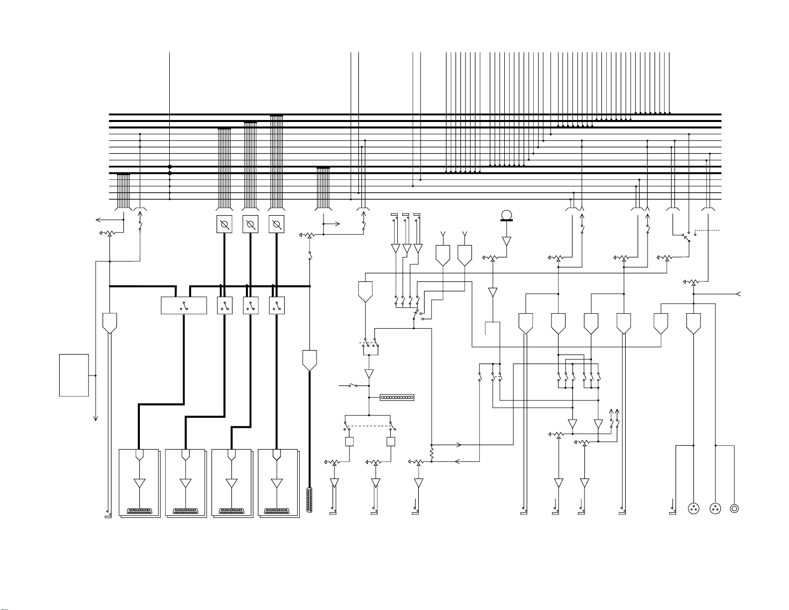
Figure 1-7 D8B Gain Structure Diagram
D8B Manual • Chapter 1 • page 16
Page 23

Specifications
Meters:
• LED ladders displaying 24 channels, 24 LEDs per
channel from –50 to 0 dBFS (0 dBFS = +20 dBu)
Frequency Response:
• 20Hz-20kHz +/-0.5 dB
Crosstalk (@ 1kHz)
• Adjacent channels: –90 dBu
• Aux sends feed through: –90 dBu
• Main outputs: –90 dBu
Equalizer
• Gain Range: ±15 dB
• Frequency range: 20Hz-20kHz
split into 4 bands
• Q: 1/12 to 3 octave
Compressor
• Threshold: –60 to –1 dB
• Attack: 0.3 ms to 2.6 sec
• Release: 80 ms to 2.6 sec
• Ratio: 1:1 to 20:1
• Output: 0.0 dB to 20 dB
Gate
• Threshold: –60 to –1 dB
• Attack: 0.1 ms to 0.6 sec
• Release: 80 ms to 2.6 sec
• Range: 0 dB to 100 dB
Analog Input/Output Section
• Output Level (0 dBu = 0.775V RMS)
• Left and Right Outputs:
+22 dBu balanced 1/4" TRS
+28 dBu balanced XLR
• Bus (Tape) out:
+22 dBu balanced 1/4" TRS
• Aux sends:
+22 dBu balanced 1/4" TRS
• Inserts:
+22 dBu unbalanced 1/4" TRS
Channel Section (mic/line)
• Line input: balanced 1/4" TRS input
• Mic Input: balanced XLR input
• Preamp dynamic range:
114 dB max.
• E.I.N.:
–129.5 dBu, 150 ohm source
–131.2 dBV, 150 ohm source
• CMRR: –83 dBu @1kHz
• Distortion: 0.005% @ 1kHz
+14 dBu output level
(20Hz-20kHz filter)
• Mic gain range: Unity to +60 dB
• Line In gain range: –20 dB to +40 dB
(channels 1-12)
–20 dB to +20 dB
(channels 13-24)
• Input max. level: +4 dBu nominal
+22 dBu clipping
• Aux send gain range: off to +10 dB
• Bus out gain range: off to +10 dB
• Threshold: –60 to –1 dB
• Ch. fader gain range: –100 to +10 dB
Digital Specs
• Converters:
24-bit, 115 dB Signal-to-Noise-Ratio (EIAJ),
106 dB Dynamic Range, 128X oversampling
• DSP:
32 bit (>190 dB dynamic range)
• CPU:
300 MHz Celeron
(166 MHz Pentium in earlier versions)
File Storage:
• Floppy drive, internal hard drive or 10-base-T
Ethernet network
Dither:
• Apogee UV22 16-bit Super CD Encoding onboard
Physical Dimensions
• Console:
8.7" x 37.6" x 27.1" (221mm x 955mm x 688mm)
• Remote CPU:
5.25" x 19.0” x 20.0" (133mm x 483mm x 508mm)
Weight
• Console:
73 lbs. (33.1kg)
• Remote CPU:
50 lbs. (22.7kg)
Note: All specifications subject to change without
notice.
D8B Manual • Chapter 1 • page 17
Page 24
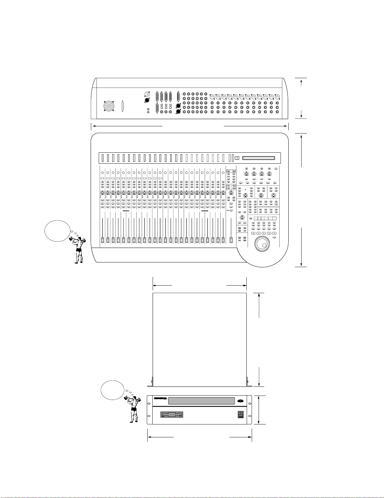
Physical Dimensions
8.7"
(221mm)
37.6" (955mm)
D8B
CONSOLE
SHIPPING
WEIGHT
73 lbs.
(33.1 kg)
D8B CPU
SHIPPING
WEIGHT
50 lbs.
(22.7 kg)
27.1" (688mm)
17.25" (43.8cm)
20" (50.8cm)
D8B Manual • Chapter 1 • page 18
CPU
19.00" (48.3cm)
3U
5.25"
(13.3cm)
Page 25

Updating Software
Software upgrades can easily be downloaded
from the Mackie website at www.mackie.com.
Find the D8B section and select “Downloads.”
Always read the Release notes that accompany the
software downloads. They contain valuable infor-
mation specific to the current software revisions
and install procedures.
Windows-based Computers
Follow these steps if you are downloading
onto a Windows
1. Download the .ZIP files d8b3xxxx_PC.zip for
the operating system installation, and the D8B
Plug-in Demo Kit (Demo_Plugins_3xxx_PC.zip)
for the plug-ins installation.
2. W e recommend that you update the operating
system first. Double-click on the d8b3xxxx_PC.zip
file. This will launch the WinZip™ self-
extraction utility.
3. The default "Unzip T o" directory is set to C:\. If
you prefer to have the files extracted to a
different location, type the path into the provided
text box and then press the Unzip button. Quit
the WinZip™ self-extraction utility.
4. Locate the two extracted files, labeled
d8b3xxxx Install 1.exe and d8b3xxxx Install
2.exe, on your hard drive.
5. Double-click on the first file, d8b3xxxx Install
1.exe, and you'll see a "WinImage™ Self
Extractor" dialog box.
6. Ensure that the "Writing On Floppy" check box
is selected, then click the "OK" button in the
upper right corner of the dialog box.
7. When the "Batch Assistant" dialog box appears,
insert a double-sided, high-density 1.44MB
floppy disk into drive A:\ and then click the
"OK" button.
8. When the Winimage™ utility has completed
writing to the first disk, be sure to label your
disks so you know which is #1 and which is #2.
Additionally, be sure not to leave either disk in
your floppy drive. Rebooting your PC with the
disk in the drive can create problems with your
PC. Repeat steps 5 through 7 for the second
disk image file.
9. With the D8B console power supply turned off,
insert installation disk #1 into the floppy disk
drive.
10. Power on the console power supply.
11. Follow the instructions on the D8B control
surface. (Note: The installer no longer uses the
VGA screen; typical boot is about 30 seconds.)
12. Place the 2nd floppy disk in the drive when
prompted by the installation software.
®
-based computer:
13. Remove the 2nd floppy disk when prompted and
power down the console power supply, then
power back on.
14. You now have the updated D8B operating
system installed.
15. Make sure you read the release notes. They
have important info about this upgrade.
Note: Repeat the above procedure with the
Demo_Plugins_3xxx_PC.zip file to install the
plug-in update. After updating the plug-ins
software on the D8B, you must perform the “Erase
UFX Memory” and “Upgrade UFX Cards”
procedures (under Windows in the upper menu
bar) to upgrade the UFX cards that are installed in
the D8B (see page 86).
Macintosh Computers
Follow these steps if you are downloading
onto a Mac OS
1. Download the self-extracting file
d8b3xxxx_Mac.sea for the operating system
installation, and the D8B Plug-in Demo Kit
(Demo_Plugins_3xxx_Mac.sea) for the plug-ins
installation.
2. W e recommend that you update the operating
system first. Double-click on the
Demo_Plugins_3xxxx_Mac.sea file to extract
the two disk images.
3. Launch Apple's DiskCopy utility (you may need
to download the DiskCopy utility from http://
www .apple.com or check the system
installations disks that came with your system).
4. Depending on your version of DiskCopy, either
click the "Load Image File..." button or choose
"Make a Floppy" from the Utilities menu.
5. Locate the image file labeled d8b3xxxx Install
1.img that was extracted onto your hard drive.
6. DiskCopy will prompt you (depending on your
version of DiskCopy) to insert a floppy disk into
the floppy disk drive. With older versions of Disk
Copy, you may need to click the "Make a copy"
button first.
7. Once the disk has been ejected from the
computer , be sure to label your disk so you know
which is #1 and which is #2. Then follow steps 4
through 6 to create the second installation disk
from the second disk image file (d8b3xxxx
Install 2.img).
8. With the D8B console power supply turned off,
insert installation disk #1 into the floppy disk
drive.
9. Power on the console power supply.
10. Follow the instructions on the D8B control
surface. (Note: The installer no longer uses the
VGA screen; typical boot is about 30 seconds.)
11. Place the 2nd floppy disk in the drive when
prompted by the installation software.
®
computer:
D8B Manual • Chapter 1 • page 19
Page 26

12. Remove the 2nd floppy disk when prompted and
power down the console power supply, then
power back on.
13. You now have the updated D8B operating
system installed.
14. Make sure you read the release notes. They
have important info about this upgrade.
Note: Repeat the above procedure with the
Demo_Plugins_3xxx_Mac.sea file to install the
plug-in update. After updating the plug-ins
software on the D8B, you must perform the “Erase
UFX Memory” and “Upgrade UFX Cards”
procedures (under Windows in the upper menu
bar) to upgrade the UFX cards that are installed in
the D8B.
Note to Macintosh USB Floppy drive users:
Apple's Disk Copy program will not work
using the above method with a USB floppy drive
because the menu option "Make a Floppy..." will
not be available. You must use Aladdin Systems'
ShrinkWrap program available for purchase and
trial download from http://www.aladdinsys.com/
shrinkwrap/index.html. Once you have
ShrinkWrap installed, substitute these steps for
steps 3-6 in the above directions.
Summary
This chapter has been specifically designed to
help you understand the basic concept of the Digital
8•Bus architecture. The following two chapters
describe the physical surface controls and the
software features and capabilities. The last chapter
describes specific applications as they pertain to
unique recording tasks and needs.
Chapters 2 and 3 support what you’ll encounter
in Chapter 4. Feel free to jump ahead, but keep in
mind that you’ll probably need to use these second
two chapters as a reference for the terms and
controls that are new to you.
3. Launch ShrinkWrap.
4. Select "Write Image back to Disk..." from the
Image menu (command-B).
5. Locate the image file labeled d8b3xxxx Install
1.img that was extracted onto your hard drive.
6. ShrinkWrap will prompt you to insert a floppy
disk into the floppy disk drive.
D8B Manual • Chapter 1 • page 20
Page 27

Where Is It?
Chapter 2
D8B Manual • Chapter 2 • page 21
Page 28
It’s Time to Locate Everything…
No matter how fast you want—or need—to get
started, take advantage of this simple map of the
territory: it provides the Fast Track overview of
the D8B. It’s amazing how artistically supportive
this console is. It’s well worth your time to take a
look at all the controls so you can put them to
work efficiently.
Rear Panel Description
This section describes rear panel connector types,
their functions, and associated signal buses.
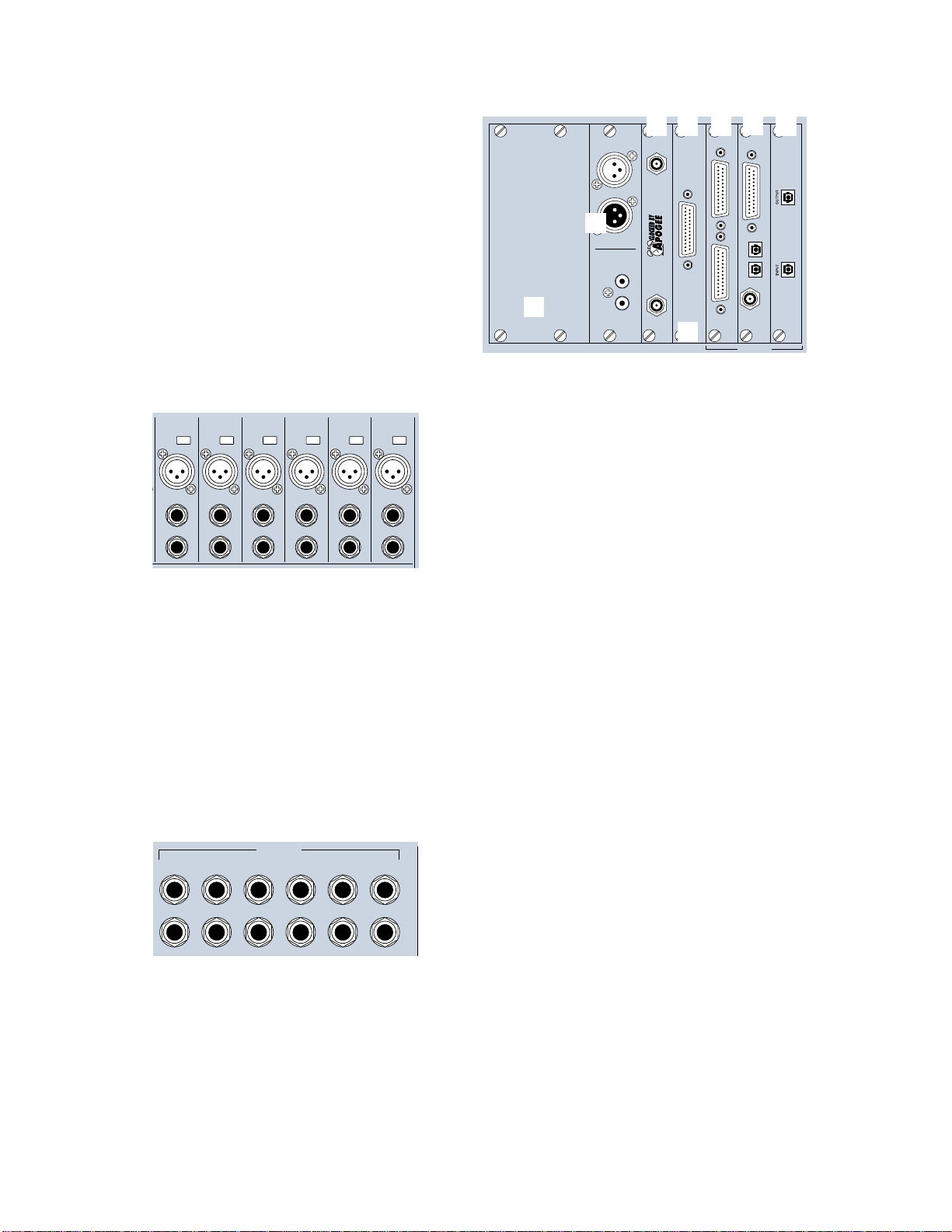
Card Cage Section
A B C D
DIGITAL I/O
AES/EBU
7
DIGITAL I/O
S/PDIF
IN
8
DIGITAL EFFECTS CARDS
OUT
DIGITAL I/O SYNC ALT I/O TAPE IN/OUTS
2
ADAT OPTICAL
ANALOG IN ANALOG OUT
3
TDIF
IN OUT
SYNC
OPT•8
4
PDI•8
1
ANALOG I/O
AES/EBU I/O
6
1
APOGEE
CLOCK I/O
IN
OUT
WORD
CLOCK
OUT
2
IN
WORD
CLOCK
5
Channels 1–12 Inputs
6
5
4
+48V
+48V
PH
MIC
LINE IN
INSERT
+48V
PH
PH
MIC
LINE IN
LINE IN
INSERT
INSERT
3
+48V
+48V
PH
PH
MIC
MIC2MIC
LINE IN
LINE IN
INSERT
INSERT
1
+48V
PH
MIC
LINE IN
INSERT
Each channel contains:
• XLR mic input. Be sure the MIC button is pressed
down on the control surface channel strip.
• Phantom power On/Off button depending on
mic requirements.
• 1/4" TRS line input—balanced or unbalanced.
Be sure the MIC switch is in the up position
on the control surface channel strip.
• 1/4" TRS channel insert/direct output jack.
Channels 13–24 Inputs
LINE INPUTS
(BAL /UNBAL)
15
16
17
18
21
22
23
24
Channels 13 through 24 have 1/4" TRS (Tip/Ring/
Sleeve) line input connectors that accept balanced
and unbalanced signals.
D8B Manual • Chapter 2 • page 22
13
14
19
20
This is where you plug in the optional I/O cards of
your choosing, to customize the Digital 8•Bus for
your own application.
There are three slots assigned as TAPE IN/OUTS.
Each slot provides I/O for 8 channels, so you can
add up to 24 tape sends and returns, or additional
inputs and outputs.
• TO TAPE (OUTPUT) – The D8B can route any
channel in Fader Banks 1, 2 and 3 to the
multitrack through these connectors. In addition,
the bus outputs in Fader Bank 4 (MASTERS) can
be routed out the tape outputs.
• FROM TAPE (INPUT) – Multitrack outputs are
fed back into channels 25–48 (Fader Bank 2)
through these connectors. Depending on the
specific I/O card, these inputs will receive any
line-level analog or digital signal.
Each I/O card contains its own labeling protocol,
but the fundamental concepts described above
pertain to all.
1 Analog I/O (AIO•8)
• Each 25-pin D-sub connector handles 8 balanced
analog channels.
• Top connectors send line-level outputs to the
multitrack (or other line-level equipment).
• Bottom connectors receive line-level analog
signal from the multitrack outputs (or other
line-level equipment).
• Each card offers I/O for 8 channels.
• Connectors are compatible with TASCAM
DA-88, 25-pin analog connectors.
2 Apogee Digital I/O (DIO•8)
• Two digital-format ins and outs: ADAT optical
(fiber optic connections) and TASCAM TDIF
(25-pin D-sub connections).
• Select one digital format at a time in the Setup
screen.
• One BNC sync connector for master clock connection from the D8B to TASCAM clock recipient.
• Use the DIO•8 card as a format converter between either optical and/or TDIF.
Page 29
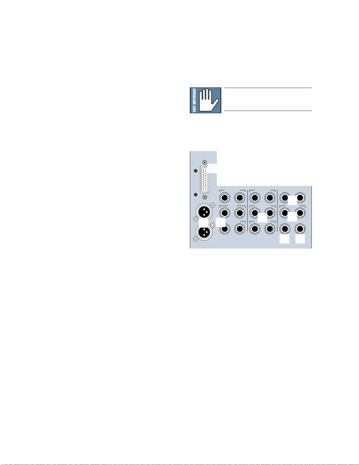
3 ADAT Optical (OPT•8)
• Two digital ADAT optical (fiber optic) connections.
• Each card offers I/O for 8 channels.
4 AES/EBU (PDI•8)
• One 25-pin D-sub connector in digital
AES/EBU format.
• Each card offers I/O for 8 channels.
5 ALT I/O Card Slot
• Using the configurable plug-in architecture,
insert plug-in capability is available for channels 1–48 (Pre- and Post-DSP), and Main Mix
L-R, in addition to internal effects sends
(Auxes 1–12).
• Effects return to the main L-R mix at Fader
Bank 3 (FX 1–16)
Reminder: Power down the system
before installing any cards!
• Separate input/output card slot offering 8
more ins and outs.
• Holds any card: AIO•8, DIO•8, OPT•8, or
PDI•8.
• Inputs show up at RETURNS faders (channels
65–72).
• Outputs are assignable to either the 8 bus outputs (BUS 1–8), the 12 Aux Sends (AUX
1–12), or the MASTER L-R outputs.
• Assignments are made in the Digital I/O menu.
6 The Clock I/O Card
• Provides word clock in and out to connect
with other digital equipment.
• For use as a master or slave clock source.
• Supports 48kHz and 44.1kHz internal sample
rates, with vari-speed capabilities.
• Supports external sample rates between
32kHz and 50kHz.
Note: The Apogee Clock I/O card replaces the
standard clock card that is shipped in the
SYNC slot with the D8B.
7 The Digital I/O Card (2-track)
• AES/EBU digital I/O. Stereo interconnect for
master record machine. Input is connected to
DIGITAL 1 in the CONTROL ROOM monitor
section.
• S/PDIF digital I/O. Input is connected to DIGITAL 2 in the CONTROL ROOM monitor section.
• Same source output as MASTER L-R.
8 Digital Effects Card Slots
• Room for four separate effects cards.
• MFX – Mackie Effects card with two stereo
processors.
• UFX – Universal DSP engine with functions
dependent on specific plug-in effects. Each
card is capable of four discrete mono, two stereo, or one stereo and two mono effects.
• Aux sends 1–12 internally route to the four
card locations.
Master Input/Output Section
BUS OUT 1-8
&
SURROUND OUT
bl
MASTER OUT
LR
CR
MAIN
bm
LR
CR
NEAR FIELD
LR
L
9
R
LR
2 TRACK IN B
LR
br
2 TRACK IN C
LR
PHONES 12 TRACK IN A
STUDIO OUT
PUNCH I/O
bp bq
MASTER OUT
9 MASTER OUTputs (1/4" TRS and XLR)
• Fed from the Master L/R fader on the console
surface.
• Both sets deliver balanced line-level signals.
However, the TRS Master Outputs also provide unbalanced line-level signals.
• Post fader, DSP, and D/A converter.
bl BUS OUT 1–8 (SURROUND OUT)
• 25-pin D-sub connector provides eight balanced line-level outputs.
• Any channel (1–48), internal effects return,
or ALT IN can be assigned to one or more bus
outputs.
• Output level is controlled by the BUS 1–8
MASTERS (Fader Bank 4).
• Carries Surround monitoring channel outputs.
D8B Manual • Chapter 2 • page 23
bn
LR
bo
PHONES 2
TALKBACK
Page 30
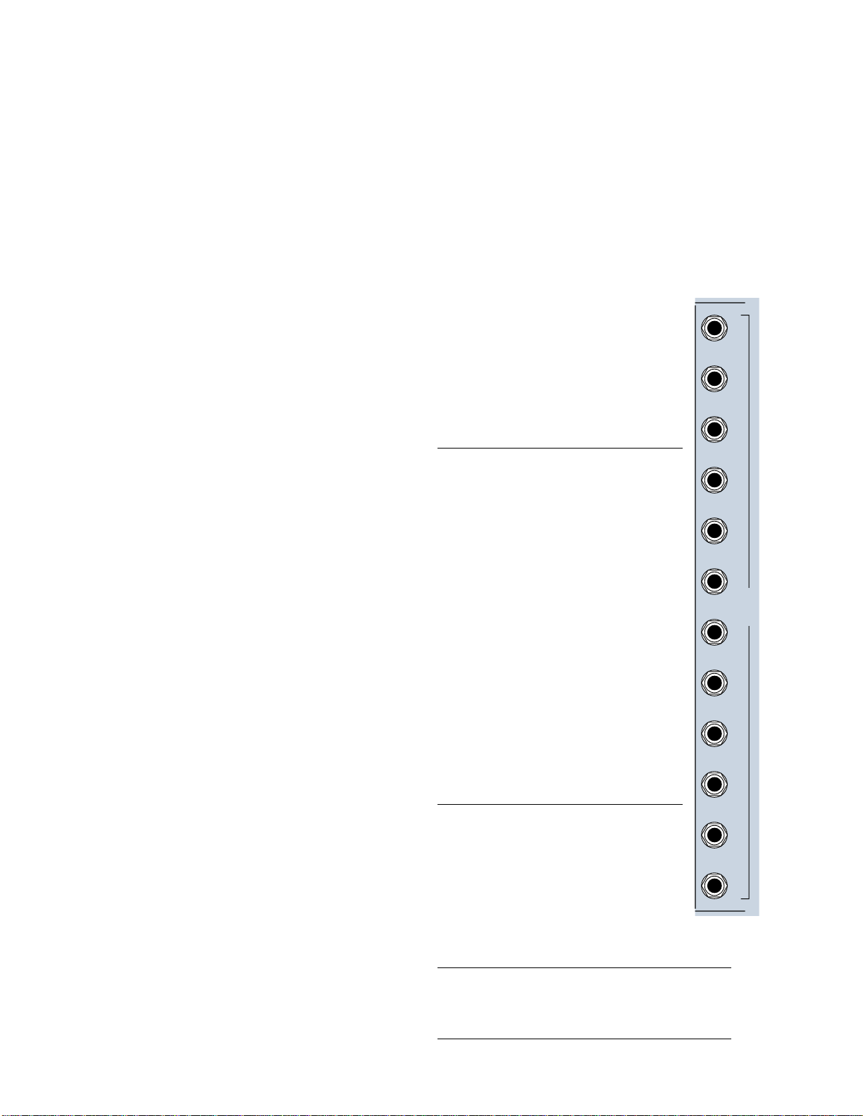
bm CR MAIN and CR NEAR FIELD
AUX
1
AUX
2
AUX
3
AUX
4
AUX
5
AUX
6
AUX
7
AUX
8
AUX
9
AUX
10
AUX
11
AUX
12
AUX OUT
(BAL /UNBAL)
br 2 TRACK A, B, and C
• Pairs of 1/4" TRS stereo line-level outputs for
sending signals to control room speakers.
• Both outputs carry the same signal (as selected
in the Control Room section).
• Levels can be adjusted independently or
linked together.
• Balanced 1/4" TRS inputs for receiving linelevel analog signals from a 2-track recorder.
• The separate left/right pairs feed the 2 TRACK
A, B, and C buses in the control room monitoring section.
• Can accept balanced and unbalanced signals.
• Post-DSP, Master L/R fader, and D/A converter.
• The signal fed to these outputs is selected in
the CONTROL ROOM section of the control
surface.
bn PHONES 1 and 2
• Each jack carries an unbalanced stereo signal
through a 1/4" TRS jack.
• Designed to connect to virtually any stereo
headphones. Phones 1 and 2 V-Pots adjust to
compensate for headphones with exceptionally high or low impedances.
AUX OUT Section
• There are 12 Aux sends available.
• Auxes 1–8 provide mono 1/4" TRS analog line-level outputs.
• Auxes 9 and 10 are linked together as a
stereo pair of 1/4" TRS analog line-level
outputs.
• Auxes 11 and 12 are linked together as
a stereo pair of 1/4" TRS analog linelevel outputs.
• The signal at these outputs is determined by
the PHONES/CUE MIX 1 and PHONES/CUE
MIX 2 source selection on the control surface.
• Aux 9–10, Aux 11–12, or the CONTROL
ROOM selection can feed either or both
Phones/Cue outputs.
• The Master L/R mix can be copied to either or
both Aux 9–10 or 11–12 Cue Mixes.
bo STUDIO OUT L-R
• Signal at these outputs is determined by the
CONTROL ROOM source selection.
• Balanced analog stereo-paired outputs for
sending signals to the studio.
• 1/4" TRS outputs can drive a balanced or unbalanced input.
• Level controlled by the V-Pot in the
SOLO/STUDIO section of the control surface,
when STUDIO LEVEL is selected.
bp PUNCH I/O
Note: Auxes 1–12 simultaneously feed the
analog Aux sends and the internal effects
cards.
Each MFX card handles two separate
mono inputs, so auxes are paired. MFX
effects returns are stereo, so each card,
while receiving two discrete mono inputs,
returns two sets of stereo outputs to the
EFFECTS Bank. Internally, Aux 1 returns
to FX 1/2; Aux 2 returns to FX 3/4; Aux 3
returns to FX 5/6; continuing through Aux 8,
which returns at FX 15/16.
UFX cards handle 4 mono, two stereo,
or one stereo and two mono inputs.
For each UFX card, no matter what the
Aux input selection, returns appear at the
FX faders numbered the same as their
respective slots.
If all UFX effects are mono, each return
correlates directly to the Slot number ( 9 to 9,
10 to 10, etc.)
• A remote switch connection for activating the
MMC master record function—to punch in or
out of record.
• Use with a normally-open switch.
bq TALKBACK
• A remote switch connection for engaging the
talkback function.
• When stereo effects are selected, regardless of the Aux input selection,
returns appear at the FX faders numbered the same as their respective slots.
For stereo effects with mono inputs, the
effects return at the respective slot
numbered pair (input 9 returns at FX 9/
10; input 11 returns at FX 11/12, etc.)
• Duplicates the Talkback switch in the CONTROL ROOM section.
• Use with a normally-open switch.
Note: Patching from an Aux output does not interrupt
the internal sends to the FX Cards, so it’s possible to
run both internal and outboard effects at the same time.
D8B Manual • Chapter 2 • page 24
Page 31

PARALLEL
5
CONSOLE DATA
KEYBOARD
4
MOUSE
1
3
2
CONCEIVED, DESIGNED, AND MANUFACTURED BY MACKIE DESIGNS INC • WOODINVILLE • WA • USA • MADE IN USA • FABRIQUE AU USA • COPYRIGHT ©1997 •
THE FOLLOWING ARE TRADEMARKS OR REGISTERED TRADEMARKS OF MACKIE DESIGN INC.: "MACKIE", "DIGITAL SYSTEMS", D8B AND THE "RUNNING MAN" FIGURE •
Remote CPU Description
Data and Synchronization I/O
These connections are specifically pertinent to
non-audio functions (or, in plain English, these
aren’t audio connections!).
Connecting a Mouse, Keyboard and
SVGA Monitor
The Digital 8•Bus is designed to work as a standalone console. However, you’ll increase your
options and productivity by using a mouse, keyboard, and SVGA monitor. Simply connect them to
the corresponding ports on the back of the Remote
CPU for access to point-and-click commands with
the mouse, as well as key commands and text entry
from the keyboard.
6
3 The SVGA Monitor
• A hi-density 15-pin D-Sub connector is provided
to connect an SVGA monitor.
• Use at least a 17" multisync SVGA monitor capable of 1024 X 768 resolution and a 72Hz
refresh rate. Larger monitors provide greater
viewing pleasure.
• Use of monitor provides graphic display and
control of most console functions, including
equalization, compression, gating, internal effects, automation editing, and file
management.
• The SVGA monitor can be connected without
turning off the Digital 8•Bus (hot-plugable).
Other Connections
4 Console Data
1 The Mouse Port
• Connect a PC-compatible mouse (PS/2 style).
• A two-button mouse is sufficient.
2 The Keyboard
• Connect any PC-compatible keyboard
(QWERTY style).
• Must have a 5-pin DIN connector. An adapter
can be used for the 9-pin keyboard connector.
Note: Turn the Digital 8•Bus OFF
before connecting these devices. The
Digital 8•Bus must boot up with these
peripheral devices connected in order
for them to work properly.
• A 25-pin D-sub connector connects the console
to the Remote CPU using the cable supplied.
5 MIDI
• MIDI card in the remote CPU uses a 9-pin
D-sub connector.
• Install the supplied 9-pin to dual 5-pin adapter
to facilitate connection to your MIDI network
using standard MIDI cables. This could be a
plastic housing adapter or a rattail 9-pin split
to 5-pin I/O connection.
• MIDI IN receives MTC, program changes, and
controller, note, and poly aftertouch messages.
• MIDI OUT sends MMC commands, program
changes, and controller, note, and poly
aftertouch messages.
D8B Manual • Chapter 2 • page 25
Page 32

6 Ethernet Port
• Accepts an RJ45 telco connector.
• Connects to PC/Mac for FTP file transfer
through a network or peer-to-peer.
• Can be used to make peer-to-peer connections
with other Digital 8•Bus consoles.
• Use CAT5 for standard network FTP connections;
use crossover CAT5 for peer-to-peer connections.
Control Surface Functions
For a road map to the various knobs, buttons,
and faders, refer to the D8B Overview section of
this manual.
2 Mic/Line Button
• On channels 1–12 only.
• This button selects between the Mic Input (XLR) and the Line Input (1/4" TRS).
• Up position selects the line input (1/4"
TRS).
• Down position selects the microphone
input (XLR).
3 REC/RDY
• The Record Ready button arms the corresponding tape track to record.
• Communicates via MMC (MIDI Machine
Control).
1
2
3
4
5
0
-
20dB
REC/RDY
ASSIGN
TRIM
I
L
M
12
MIC
WRITE
N
E
C
I
+40dB
60
Channel Strip Section
The channel strip on the Digital 8•Bus is very
much like the channel strip on an analog mixer.
Each channel offers the same set of controls, with
a few exceptions. Even with a brief overview of
each control, you’ll find your understanding of the
digital mixing concept closely related to what you
already know about analog mixers—that’s the
beauty of this console design.
• There are 24 channel strips.
• There are four layers (Fader Banks) of feature
sets: MIC/LINE (1–24), TAPE IN (25–48),
EFFECTS (49–72), and MASTERS.
• Channels 1–12 have both mic and line input
capabilities.
• Channels 13–24 have line input capabilities only.
• Channels 25–48 receive signal only from the
I/O card inputs.
1 Trim Level
• At the top of each channel strip
• The Trim Level controls only input levels for
channels 1–24.
• Regardless of bank selection, trims are active and
available for channel inputs 1–24. This is handy
for tweaking without having to switch banks.
• Used to adjust and optimize input levels.
• This control is one of the few not written in a
snapshot.
Note: The TRIM levels at the top of each of the 24
channel strips and the MIC buttons at the top of the
first 12 channel strips are not written into automation
or snapshots. Careful notes as to their status should
be manually archived—as in written down—for future
reference. However, if TRIMs are all left at unity gain—
or at least left untouched—throughout the entire
session, the console is capable of perfect, total recall!
We highly recommend this technique.
4 Assign
• Routes audio to output buses 1–8.
• Routes audio to the Master L-R bus.
• Assigns the selected channel to the
channel strip’s corresponding tape track
for recording. For example, after selecting ROUTE TO TAPE in the
ASSIGNMENT section, press SELECT
on channel 2, then press the ASSIGN
button on channel 12 to route the signal
from channel 2 to tape track 12.
5 Write
• Manually enables a channel for recording to automation.
• Blinks when on standby; solid when active.
• Automatically lights when Auto Touch
automation has been activated.
6 Channel V-Pot
• A multifunctional digital control and
level display.
• Controls channel pan when PAN is selected in the Master V-Pot section (just
to the right of channel 24).
• Controls Aux send levels when Aux
1–12 is selected in the AUX section (just
above the Master V-Pot).
• Controls panning between stereo Auxes
9/10 and 11/12 when PAN is selected
below either send.
• Controls channel Level to Tape and Digital Trim whenever they’re selected
(immediately above Aux 1 and 2 select
buttons).
• Displays return fader levels (Bank 2)
when level to tape follows faders.
6
8
9
bl
bm
MIDI 4
dB
10
5
U
5
10
20
30
40
50
60
12
36
SELECT
SOLO
MUTE
FX 12
12
36
7
D8B Manual • Chapter 2 • page 26
Page 33

7 Fader Bank Select LEDs
• Just below the channel V-Pots.
• When the green LEDs are on, Fader Bank 1 is
selected (MIC/LINE).
• When the red LEDs are on, Fader Bank 2 is
selected (TAPE IN).
• When both LEDs are on, Fader Bank 3 is selected (EFFECTS).
• When neither LED is on, Fader Bank 4 is selected (MASTERS).
8 Select
• Chooses a channel to be edited.
• Enables onboard or on-screen Fat Channel
control over the selected channel.
• Operative for copying and pasting data between channel strips.
• Part of the grouping and linking procedures.
• Double-clicking the SELECT button opens and
closes the strip’s on-screen Fat Channel.
• Pressing and holding opens a channels preferences page in the VFD, which controls basic
channel parameters.
• Pressing and holding two SELECT buttons at
once opens a Link options page in the VFD.
• Aux Solo is accomplished by selecting an aux
bus, then pressing the SOLO button by the
Master V-Pot. When this solo light is on, the
Master V-Pot adjusts the solo level.
• Soloing multiple channels is accomplished
by holding the shift key (onboard or keyboard)
while pressing the solo buttons on all desired
channels or, by holding one solo down while
pressing others. Also, selecting “Solo Latch”
in Setup > Mix Options keeps solos selected
until they’re manually switched off.
• Solo Isolate mode is accomplished by holding
down the Alt key on the keyboard or control
surface while pressing a channel’s solo(s). A
solo isolated channel is always active to the
solo bus and therefore will not mute when
other channels are soloed. Only PFL solo
mode overrides Solo Isolate mode.
bl Mute
• Mutes the signal after the channel fader.
• Prior to the L-R output bus.
• Prior to Bus 1–8 outputs.
• Does not affect the Direct Out to Tape unless
console is configured for Faders to Tape mode.
bm Channel Fader
9 Solo
• Pressing Solo on any channel lets you hear
only the soloed channel.
• Mackie’s exclusive Rude Solo Light flashes incessantly whenever any channel is soloed.
• There are three different types of soloing
available: PFL, AFL, and Mixdown.
• PFL (Pre-Fader Listen) solos the signal before
it gets to the fader. PFL is a monitor function
only and has no effect on the Master L-R mix
send. Any channel is soloed in mono, regardless of pan position. PFL solo level is
unaffected by fader changes.
• AFL (After-Fader Listen) solos the signal af-
ter the fader in the signal path. Therefore, solo
level is affected by fader movement. AFL solos
the accurate pan positioning and, like PFL, is
only a monitor function not affecting the Master L-R mix.
• Mixdown Solo is a post-fader, pan-accurate
solo that overrides the Master L-R mix.
• Clear Solo, in the Solo/Studio section, re-
leases any solo selections. This is particularly
useful when working with solos across multiple fader banks.
• Controls the signal level from the channel to
the bus or buses it is assigned to (typically the
L/R Master Fader and the Bus 1–8 output).
• Doesn’t affect the signal level to the Tape Outputs unless specifically routed to do so, or if
console is configured for Faders to Tape mode.
Channel Meters
• Indicate post-EQ, pre-fader levels.
• The audio level display is scaled in digital
dBFS (decibels full-scale).
• 0 dBFS = +20 dBu (Clipping occurs at +22
dBu.)
• –15 dBFS = +5 dBu
• The minimum displayed level is –50 dBFS.
• Markings next to the LED ladders are denoted
as –50 dBFS to OL; they are similar in function to those of digital recorders. Each
LED-segment is accurate within ±1 dB.
Note: Typically, in digital recording devices such as
MDMs, HDRs, or DATs, there is a built-in overhead of
3–4 dB above the 0 dBFS mark to match the typical
maximum unbalanced analog console bus output value
of +22 dBu. The OL LED lights at +22 dBu.
D8B Manual • Chapter 2 • page 27
Page 34

Master Section Description
The Master Section—everything to the right of
channel strip 24—is divided into 13
subsections. They are:
• Master Fader/Bank Select Section
• Master V-Pot Section
• V-Pot Assign Section
• Fat Channel Section
• Studio/Solo Section
• Phones/Cue Mix Section
• Control Room Section
• Clipboard Section
• Master Fader/Shortcuts Section
• Bus Assignment Section
• Automation Section
• Session Setup Section
• Transport Section
Master Fader/Bank Select
Section
This section consists of:
• The four buttons used to select the four Fader
Banks.
• The SHIFT button, which is primarily used to
select and deselect multiple channels.
• The Master L/R Fader, which controls the signal
level going to the L-R stereo bus.
All 96 channels are always active. However
only 24 are available at a time from the control
surface (up to 48 are available through the onscreen interface). The buttons used to select the
active fader set are:
• MIC/LINE (TRACK)
• TAPE IN (MONITOR)
• EFFECTS
• MASTERS
V-Pot Select
Master Section
Fat Channel
MIC/LINE (TRACK)
• Fader Bank 1.
• Selects channels 1–24.
• Combination of Microphone
inputs 1–12 and line inputs
1–24.
TAPE IN (MONITOR)
• Fader Bank 2.
• Selects channels 25–48.
• Requires 1–3 Tape I/O
cards installed in the card
cage for input signals.
D8B Manual • Chapter 2 • page 28
Master V-Pot
Bus Assignment,
Control Room
Master Fader,
Bank Selection
Clipboard, Master L/R,
Shortcuts
Solo/Studio,
Phones 1 & 2
Automation,
Setup
Transport
Page 35

49-72
EFFECTS
BANK SELECT
SHIFT
25-48
TAPE IN
MASTERS
1-24
MIC /LINE
(TRACK) (MONITOR)
MASTER
L/R
dB
10
5
U
5
10
20
30
40
50
60
SHIFT Button
The SHIFT button serves multiple functions.
It provides a way to select multiple channels and
multiple solo buttons. It also serves as a fine-tune
selector for Aux levels and Pan adjustments. Try
adjusting an Aux level with and without the
SHIFT button depressed—notice the difference in
numerical scrolling speed.
• Allows more than one channel SELECT button
to be engaged simultaneously.
• Allows more then one SOLO button to be engaged simultaneously.
• When SHIFT is pressed, the Rude Solo Light
illuminates.
• Allows fine-tuning of Aux send levels and pan
adjustments.
• Allows independent control of channel parameters with linked channels.
• Double-clicking selects all channels on the active fader bank.
Master L/R Fader
• 100mm logarithmically-tapered fader for
smooth fades.
• Remotely controls level via DSP—doesn’t
pass audio like a traditional fader.
• dB level ranges from +10 dB (fully on) to –∞
(fully off).
• Mixdown Solo level control.
• Provides level adjustment to tape outputs (if
desired).
EFFECTS
• Fader Bank 3.
• Selects channels 49–72.
• Effects bank controls sixteen internal effects
returns and eight ALT I/O returns.
MASTERS
• Fader Bank 4.
• Selects channels 73–96.
• Faders 1–8 control the virtual group levels.
• Faders 9–16 are assignable MIDI controllers.
• Faders 17–24 control the eight bus or
surround outputs (BUS 1–8), which are output
via the 25-pin D-sub connector labeled BUS
OUT 1–8 & SURROUND OUT on the rear of
the console. The BUS 1–8 outputs can also be
assigned to the 24 tape outputs, or the
ALT I/O slot.
Master V-Pot Section
MASTER
PAN
MASTER V-Pot
• Acts as the Master level control for the currently selected Aux bus.
• In all surround mode settings, the MASTER
V-Pot acts as the front/rear pan control for the
selected channel (provided the PAN button is
lit). When used along with the channel pan
V-Pot, the D8B acts like an audio rendition of
the family favorite Etch-A-Sketch
D8B Manual • Chapter 2 • page 29
SOLO
®
!
Page 36

MASTER PAN
AUX 1–8 Buttons (Default Operation)
• Assigns all applicable channel V-Pots to act as
pan controls (channels 1–72 and 81–88).
• Stays lit continuously until an Aux Select,
Level to Tape, or Digital Trim button is engaged.
MASTER SOLO (Aux)
• Solos the currently selected Aux.
• Only one Aux can be soloed at a time.
• Master solo can be active at the same time a
channel is soloed.
• Aux bus remains soloed until it is manually
disengaged or until the CLEAR SOLO button
is pressed.
• Solo level is post the MASTER V-Pot.
• Master Solo is not affected by the PFL or AFL
Solo status selected in the Studio/Solo section.
V-Pot Assign Section
These buttons:
• Assign the channel V-Pots to control individual
aux send levels.
• Assign the channel V-Pots to control individual
channel trim or tracking output levels.
1-24 1-48
LEVEL TO TAPE
AUX 1
AUX 3
DIGITAL TRIM
AUX 2
AUX 4
This description highlights the default
configuration for aux sends and effects returns.
Keep in mind that the new D8B plug-in architecture
provides maximum flexibility and awesome creative
capabilities with respect to plug-ins, aux sends,
and returns.
• Pressing any Aux 1–8 assigns channel V-Pots
to control individual send levels to AUX 1–8
output.
• Each Aux 1–8 is simultaneously routed to the
corresponding 1/4" jack on the rear of the
console and to an internal effects processor.
• Patching from the Aux 1–8 jacks does not
interrupt the signal flow to the internal processors.
• Each Aux 1–8 acts as a mono send to a stereo
internal effects processor (MFX card only).
UFX cards offer complete flexibility.
• Auxes patched to the IVL Vocal Studio effects
return to four channels, either in stereo pairs
(second pair is the reverb return) or as four
separate channels.
AUX 9–10 and 11–12
• Configured differently than Auxes 1–8.
• Each channel has a stereo pair of controls:
one level and one pan. This is ideal for
phones/cue mixes or for an additional recording feed in a live setting.
• Pressing Aux 9–10 assigns the channel V-Pot
to control the send level for the stereo pair.
• Pressing Pan under Aux 9–10 assigns the
channel V-Pot to adjust pan positioning between
the stereo pair.
• Aux 9–10 are not routed to the internal effects
processor by default, but may be assigned as
such in the plug-in configuration window.
• Aux 11–12 operates identically to Aux 9–10.
AUX 5
AUX 7
AUX 9-10
PAN
AUX 6
AUX 8
AUX 11
PAN
D8B Manual • Chapter 2 • page 30
LEVEL TO TAPE
• Level to Tape assigns the channel V-Pots as
tape output level controls via the I/O cards.
• This control is post channel DSP and prefader. Fader adjustments don’t affect tape
-
12
output levels.
• Facilitates optimizing the gain structure from
the beginning to the end of the signal path,
when used correctly.
• When Faders to Tape is active, the level to
tape is derived from the source channel faders
instead of the channel V-Pots—the level is
post-fader.
Page 37

Figure 2-1 Aux Sends 1-8 (Default – Mackie Stereo Effects [MFX])
OUT
Internal Effects Processor 1
OUT
Internal Effects Processor 2
OUT
Internal Effects Processor 3
Internal Effects Processor 4
OUT
FX 1 FX 2
FX 3 FX 4
IN
IN
IN
IN
FX 5 FX 6
Aux 1 – 4
TRS Out
1-24 1-48
LEVEL TO TAPE
AUX 1
AUX 3
AUX 5
AUX 7
AUX 9-10
PAN
FX 7 FX 8
DIGITAL TRIM
AUX 2
AUX 4
AUX 6
AUX 8
AUX 11
-
12
PAN
FX 9 FX 10
Aux 5 – 8
TRS Out
FX 11 FX 12
IN
Internal Effects Processor 5
IN
Internal Effects Processor 6
IN
Internal Effects Processor 7
IN
Internal Effects Processor 8
OUT
FX 13 FX 14
OUT
OUT
OUT
FX 15 FX 16
LR
LR
LR
Eight mono aux sends, each returning a stereo effect
DIGITAL TRIM
• Pressing the DIGITAL TRIM button assigns
the channel V-Pots to become digital trim
(digital input level) controls.
• Functionally located immediately after the A/D
converter in the signal path for channels 1–48.
• When using digital I/O cards, for channels
25–48, there is no A/D converter, so the digital trim is simply the first control in the signal
path after the card.
• Digital Trim is a recallable function, unlike
the analog Trim control. It can be automated
or stored in a snapshot.
• Digital Trim is the only input trim control for
channel inputs 25–48.
Talkback Mic
• Located just above the LEVEL TO TAPE and
DIGITAL TRIM buttons.
• The Talkback mic is activated two different
LR
LR
LR
LR
LR
ways: 1) by pressing Talkback in the Control
Room section, 2) by pressing a foot pedal connected to the Talkback jack in the rear of the
console.
• Talkback audio is sent to the Phones/Cue
Mixes when pressing Talkback or depressing
the foot pedal, or to the Studio monitor system
when pressing Talkback to Studio.
Left/Right LED Ladders (Master Meters)
• Located above the Talkback Mic.
• Indicates the signal level of whatever is selected in the Control Room section.
• When Solo is selected, the Master Meters indicate the level of the combined soloed channels.
• When Mono is selected in the Control Room
section, both Left and Right meters indicate
the mono level.
D8B Manual • Chapter 2 • page 31
Page 38

CHANNEL Select Display
V-Pots and SELECT buttons
• Just to the right of the L-R Meters.
• Numeric readout indicates the selected channel
—the currently editable channel in the VFD.
CHANNEL
OL
2
4
7
10
15
20
25
30
35
40
50
LEFT RIGHT
Fat Channel Section
The onboard Fat Channel provides access to all
those really cool dynamics and EQ functions. It
also provides for configuring Setup parameters,
loading, and saving patch information.
The on-screen Fat Channel is an amazing
interface that provides the look and feel of a
vintage tool as well as precision control and
recall.
Fat Channel Display
• VFD Vacuum Fluorescent Display.
• Provides a text interface to console operation.
Nearly all static functions and controls are
accessible.
• Four Select buttons and V-Pots used to select
and adjust options that show up in the Fat
Channel VFD.
• Pressing Select above a Fat Channel V-Pot
lets the user adjust or scroll through the
pertinent options.
• V-Pots rotate 360˚ and display the relative
adjustment positions as provided by eleven
discrete LEDs.
PREVIOUS and NEXT arrows
• Pages the VFD to more parameters whenever
more than four adjustments can be made.
• The PREVIOUS button scrolls the VFD to
the left.
• The NEXT button scrolls the VFD to the right.
• An arrow on the left-hand side of the VFD,
pointing left, indicates a previous page is
available.
• An arrow on the right-hand side of the VFD,
pointing right, indicates the next page is
available.
SUPER CD ENCODING
EQ
GAIN
-1.0 dB
SELECT
LOWPREVIOUS
ON
D8B
+2.2 dB
LOW MID HI MID
COMPRESSORGATE
56 INPUT / 72 CHANNEL DIGITAL MIX ER
GAIN
GAIN
0.0 dB
SELECT SELECT
SETUP
MEMORY A
PLUG-INS
GAIN
+3.1 dB
SELECT HELP
HI NEXT
MEMORY B
LOAD PATCH
SAVE PATCH
The Fat Channel
D8B Manual • Chapter 2 • page 32
Page 39

ON button
SAVE PATCH button
Toggles the selected Fat Channel DSP control
parameters on and off in bypass fashion.
SETUP button
When EQ is selected in the Fat channel, the Setup
button lets you select the type of equalization and
activate the “EQ to Dynamics” mode.
MEMORY A and B buttons
• Each channel has two memory locations for
EQ, compressor, gate, plug-ins, and surround
parameter comparisons.
• Any changes to the above controls are temporarily stored in the selected Memory A or B
buffers.
• Simply press Memory A to instantly recall the
settings you developed while Memory A was
selected. Press Memory B to instantly switch
to alternate settings.
• Automation of the parameters will overwrite
the buffers unless bypassed.
EQ button
Press this button to store an individual EQ,
compressor, or gate into the current Fat Channel or
plug-in setting to the onboard library. You must
choose EQ, Gate, Compressor, or a plug-in before
trying to save a patch.
Studio/Solo Section
This section contains a V-Pot to control Studio,
Solo, and Talkback levels, along with buttons to
select various solo functions and talkback to the
studio monitor system.
MIXDOWN SOLO button
• This solo status interrupts the L-R Main outputs to front-of-house speakers or 2-track
recorders. It is the destructive solo.
• Use this mode whenever you want the soloed
track(s) to be the complete mix—a rhythm
breakdown is a good example of this.
• Mixdown Solo is post-fader and DSP. Level to
tape (e.g., 2-track mixdown recorders) is controlled by the Master L/R fader.
Press this button to see EQ parameters for the
selected channel in the onboard Fat Channel display.
GATE button
Press this button to see Gate parameters for the
selected channel in the onboard Fat Channel display.
COMPRESSOR button
Press this button to see Compressor parameters
for the selected channel in the onboard Fat Channel
display.
Note: Fat Channel SELECT and page (PREVIOUS
and NEXT) buttons are used as additional view tools.
PLUG-INS button
• Press this button and use the prompts from
the VFD to select and navigate through the
various plug-in specific parameters.
• Use the “Next” and “Previous” buttons to page
through all available parameters.
Onboard control of plug-ins is intuitive for
basic functionality. Refer to the individual Plug-ins
Manual for details regarding the use of each plugin via the control surface or on screen.
LOAD PATCH button
STUDIO/SOLO
MIXDOWN SOLO
PFL SOLO
AFL SOLO
TALKBACK TO
STUDIO
RUDE SOLO
LIGHT
LEVEL
CLEAR SOLO
SOLO LEVEL
STUDIO LEVEL
TALKBACK LEVEL
PFL SOLO button
• Activates Pre-Fader Listen on the solo bus.
• Accesses the signal before it gets to the fader,
so the fader has no effect on the soloed signal.
• This is a mono-centered solo feature. Pan has
no control over this solo feature.
AFL SOLO button
• Activates After-Fader Listen on the solo bus.
• Accesses the signal after the fader, so fader
moves do affect the soloed signal.
• This is a stereo—post-pan control—bus so
soloed channels are heard in their correct pan
position.
Press this button to load an individual EQ,
compressor, or gate into the currently selected
channel. Plug-in settings previously stored in the
onboard library can be loaded into an FX card. DSP
type must be selected first.
Note: PFL/AFL only affects channel soloing and has
no effect on aux send soloing.
D8B Manual • Chapter 2 • page 33
Page 40

TALKBACK TO STUDIO button
AUX 11-12
Routes sound arriving at the in-panel Talkback
mic to the Studio outputs.
Note: Make sure the speakers that are connected to
the Studio Outs are located in another room to avoid
feedback when the TALKBACK TO STUDIO button is
depressed.
CLEAR SOLO button
Disengages all engaged solo buttons throughout
the entire console. This is especially convenient
considering sections may be soloed across multiple
fader banks.
SOLO LEVEL button
Assigns the V-Pot in the Studio/Solo section to
adjust the solo level being fed to the Control Room
outputs. Not applicable to mixdown solo (use L/R
fader to adjust mixdown solo level).
STUDIO LEVEL button
Assigns the V-Pot in the Studio/Solo section to
adjust the output level being fed to the Studio
monitor system.
TALKBACK LEVEL button
Assigns the V-Pot in the Studio/Solo section to
control the preamp level for the in-panel Talkback Mic.
Assigns the Aux 11-12 mix to the Phones output.
COPY MIX TO CUE button
Pressing this causes all channel settings to be
copied to the channel V-Pots for the selected CUE
MIX 1 (Aux 9-10) or CUE MIX 2 (Aux 11-12). This is
a very quick way to copy the MASTER L-R mix,
including effects, to the phones output, which can
then be easily fine-tuned.
CONTROL ROOM button
Assigns whatever is selected in the Control Room
section to the Phones output. Solos are also routed
to the Phones output when Control Room is selected.
LEVEL V-Pot
Adjusts the Phones output level.
Control Room Section
These buttons:
• Select the source for the control room outputs.
• Select Main or Nearfield control room outputs.
• Adjust the listening level.
CONTROL ROOM
2 TRACK A
2 TRACK B
DIGITAL IN 1
DIGITAL IN 2
RUDE SOLO LIGHT
• Blinks whenever a Solo button is engaged.
Phones/Cue Mix Section
PHONES/CUE MIX 1
COPY MIX TO CUEAUX 9-10
AUX 11-12
CONTROL ROOM
LEVEL
Phones/Cue Mix 1 and 2 select the sources and
sets levels for the Phones outputs.
AUX 9-10
Assigns the Aux 9-10 mix to the Phones output.
PHONES/CUE MIX 2
AUX 9-10
COPY MIX TO CUE
AUX 11-12
CONTROL ROOM
LEVEL
2 TRACK C
NEAR FIELD
SPEAKER LEVEL
DIM
MONO
SPEAK ERS
MASTER
L-R
MAIN
TAL KB AC K
2 TRACK A, B, and C buttons
• Selects the signal at the 2 Track A, B, or C input as the Control Room source.
• These inputs can be selected independently or
together for simultaneous playback along with
the MASTER L-R button.
Note: When DIGITAL IN 1 or DIGITAL IN 2 are selected,
MASTER L-R and 2-TRACK inputs are unavailable.
D8B Manual • Chapter 2 • page 34
Page 41

DIGITAL IN 1 button
PAS TE
UNDO
CUT/ZERO SET
COPY
CLIPBOARD
TALKBACK button
Selects the AES/EBU digital input as the Control
Room source.
DIGITAL IN 2 button
Selects the S/PDIF digital input as the Control
Room source.
MASTER L-R button
Selects the main L-R output bus as the Control
Room source.
MONO button
Combines the left and right channels to a
monaural signal and sends it to the left and right
Control Room outputs (Near Field or Main). This
provides for a quick check on the sound of the mix in
mono.
NEAR FIELD button
Turns on the Control Room Near Field output.
MAIN button
Turns on the Control Room Main output.
Routes the signal arriving at the in-panel
Talkback Mic to Phones/Cue Mixes 1 and 2 (and to
Studio Out if Talkback to Studio is selected).
Clipboard Section
Provides cut, copy, paste, and undo functions for
specific fader operations, channel parameters, and
automation events.
CUT/ZERO SET button
• Deletes edited parameters from the currently
selected channel(s) and returns them to their
default settings.
• Static or automated options are selected in the
Fat Channel display.
• The parameter settings are placed on the clipboard for desired paste operations.
Note: The Near Field and Main speaker selections
cannot both be on at the same time.
SPEAKER LEVEL V-Pot
• Adjusts the individual level of the selected
Control Room output (Near Field or Main).
• This control does not affect the level sent to
the Phones/Cue, or Master L-R mix
outputs.
• Near Field and Main levels are completely
independent of one another unless linked together in the Mix Options of the on-screen
Setup window.
• When linked, the level control is identical for
Near Field and Main. The link can be temporarily broken by pressing the Shift key and
adjusting the Speaker Level V-Pot. This is an
excellent way to set a fixed level offset between
monitor sets.
DIM button
Quickly attenuates the control room monitors by
20 dB. This is very useful for phone calls or visits
from the neighborhood volume cop.
COPY button
• Copies parameters from the currently selected
channel(s).
• Static or automated options are selected in the
Fat Channel display.
• The parameter settings are placed on the clipboard for desired paste operations.
PASTE button
Pastes copied parameters to the currently
selected channels.
UNDO button
• Reverts the currently selected channels to their
previous status, before a cut, copy, or paste.
• Multiple Undo and Redo operations are available by pressing UNDO in the Clipboard
section then Undo and Redo in the control surface Fat Channel VFD.
D8B Manual • Chapter 2 • page 35
Page 42

Master L–R/Shortcuts Section
L-R button
MASTER L/R SHORTCUTS
SELECT
WRITE
CONTROL
ALT
SELECT button
Selects the Master Fader and Aux Master for
edit operations.
WRITE button
Displays automation status and engages the
Master Fader and Aux Master to record automation
events—dependent on the automation mode.
CONTROL button
Used in combination with other buttons as a modifier
key. See Shortcuts (Appendix D) for a list of applications.
ALT button
Used in combination with other buttons as a modifier
key. See Shortcuts (Appendix D) for a list of applications.
Bus Assignment Section
• When L-R is selected, the individual channels
can be assigned or removed from the Master
L-R bus.
• Mic, Line, FX, and Returns (Channels 1–72) can
all be assigned in this way to the L-R Master bus.
ROUTE TO TAPE button
• Assigns a selected channel to any or all of the
24 tape outputs.
• Any of the 48 channels, as well as any internal
FX returns, Alt I/O return, or Bus 1–8 can be
assigned to one or more, or all (24) Tape Outputs.
• When ROUTE TO TAPE is selected, press the
SELECT button on the channel you want to
route to tape, then press ASSIGN on the channel
strip that corresponds to the desired Tape Output.
• No two channels can be assigned to the same
tape output (you can assign two or more channels to a bus, and route the bus to tape). As
soon as a channel is assigned to a previously
assigned output, it takes over the output, thus
removing the previous assignment.
Note: Great care should be taken whenever a channel
is assigned to its own tape track. Beware the dreaded
feedback loop. Ouch!
This is a quick and easy way to assign, or tell what’s
been assigned to, Bus 1–8 or the Master L-R bus.
ASSIGNMENT
ASSIGN ASSIGN
BUS 1
ASSIGN ASSIGN
BUS 3 BUS 4
ASSIGN ASSIGN
BUS 5
ASSIGN ASSIGN
BUS 7
ASSIGN ASSIGN
L-R
BUS 2
BUS 6
BUS 8
ROUTE TO
TAPE
BUS 1–8 buttons
• Only one bus may be selected in the assignment
section at a time.
• Bus assigns are used along with the individual
channel Assign buttons.
• Press any Bus 1–8 button. Any channel that’s
assigned to the selected bus will have its Assign
button lit on the individual channel strip (on
the currently selected bank).
• Pressing the channel Assign button so the
light stays on will assign that channel to the
selected bus. Pressing Assign so the light
goes off removes the assignment.
Automation Section
What Is Automation All About?
Even if you’ve never worked with an automation
system, you’ll find the controls in the Mackie Real
Time OS intuitive and powerful. Spend a little time
grasping the concepts, then start mixing.
If you’ve worked with other automation
systems you’ll find the Mackie OS incredibly quick
and easy to master. A complete digital system
that’s been designed well is amazingly powerful
and easy to use. Have fun!
AUTOMATION
BYPASS
FADER MOTORS
OFF
FADERS
PAN
MUTES
ALL
BYPASS button
• Bypasses the playback of all currently written
automation moves.
AUTO TOUCH
TRIM LEVELS
D8B Manual • Chapter 2 • page 36
Page 43

• This button must be turned off before any automation can be recorded or played back.
• Toggling Bypass doesn’t affect the automation
filter LEDs (Faders, Mutes, Pan, All). However, when Bypass is on no automation data
will be recorded.
FADER MOTORS OFF button
• Pressing this button (so the yellow light is on)
disengages fader motors, which prevents any
automated fader movement during automated
playback.
• When the button is engaged, all faders snap to off.
• Turning fader motors off does not affect
changes that have been recorded during automation record passes. All automated levels still
play back even though the faders don’t move.
• The on-screen faders still show movement
even when the physical faders are off. Fader
moves may still be written to automation using
the mouse.
FADERS button
Allows writing of Fader moves during an
automation pass. When FADERS is activated, all
fader moves on write-enabled channels are written
into automation. Can be used in conjunction with
MUTES, PAN, and ALL.
MUTES button
Allows writing of mutes during an automation
pass. When MUTES is activated, all mutes on writeenabled channels are written into automation. Can
be used in conjunction with FADERS, PAN, and ALL.
PAN button
Allows writing of Pan moves (stereo and
surround) during an automation pass. When PAN is
activated, all pan changes on write-enabled channels
are written into automation. Can be used in
conjunction with FADERS, MUTES, and ALL.
AUTO TOUCH Mode
• Activates Auto Touch write mode for automation data.
• All activated automation control points become write-enabled and enter automation
record mode at the instant they’re modified
from their current state.
• It’s not necessary to engage individual channel WRITE buttons in this mode. Manually
engaging WRITE in this mode only affects
fader, mute, and pan writing (if they’re activated in the Automation section).
• The channel WRITE button illuminates as soon
as a channel function is manually adjusted
(and the corresponding filter is activated).
• One or more of the automation buttons (FADERS, MUTES, PAN, or ALL) must be activated
or nothing will be written to automation.
Note: Fader, mute, and pan data may be overwritten if these filters are activated and the
channel is write-engaged.
TRIM LEVELS button
• Activates Trim Level automation on all writeenabled channels. This refers to trimming
automated moves up or down, not to analog or
digital level trim controls.
• All faders move to unity (U) and fader motors
are turned off.
• Previously recorded automation remains intact. However, fader and V-Pot changes are
simply added to or subtracted from existing
data.
• This is a good way to edit parts of an automation track. See “Modify Levels” on page 55 for
level-adjusting an entire track.
ALL button
• Allows writing of all automation parameters
other than faders, mutes, and pan.
• In order to record an automation pass, recording every automatable parameter, FADERS,
MUTES, PAN, and ALL must be activated.
• Parameters selected by the ALL button are
Aux 1–12 levels, Aux 9–12 pans, Master Aux
levels, Digital Trim, all channel DSP functions
(EQ and Dynamics), plus Plug-in/Effects parameters, bus assignments, surround panning, etc.
D8B Manual • Chapter 2 • page 37
Page 44

Session Setup Section
GROUP button
SETUP
SAVE
GROUP
SAVE AS... NEW
GENERAL P LUG INS DIGITAL I/O
LOAD
Buttons in this section are used for file maintenance and for setting up system functions such as
Virtual Groups, Digital I/O, meter assignment, and
MIDI parameters.
SAVE button
• Saves the currently active session to the internal
hard drive or floppy drive. We recommend using the floppy only for backup.
• Saves all snapshot and automation data as
well as the status of all digital parameters at
the time of saving.
SAVE AS… button
• Saves the currently active session under a
new name.
• Uses the V-Pots and SELECT buttons in the
Fat Channel display to rename and complete
the operation.
• To finish the SAVE AS… either press Select
beneath SAVE in the onboard Fat Channel display or simply press SAVE AS… a second
time.
• To quick-save the proposed file name, simply
double-click SAVE AS…
• Brings up the Group menu in the Fat Channel
display.
• This is a virtual group function where faders
and mutes are linked to one master fader, solo,
and mute button in the Master fader bank.
• After pressing GROUP, press the SELECT buttons on each channel strip to be included in
the group, then press Exit to complete the action.
• Control the group from the Master fader bank,
where faders strips 1–8 control groups 1–8.
GENERAL button
Brings up the General menu in the Fat Channel
display. Provides access to:
• Solo settings
• The surround sound matrix
• MIDI Machine Control settings
• Console layout (channel reassignment)
• Record Safe and Write Ready status settings
• VFD display brightness
• Network cascading and Alt I/O assignments
• One-button record status
• About current OS version
PLUG-INS button
Brings up the Plug-In menu in the Fat Channel
display for selecting the effects package to load into
the internal FX card. Refer to the individual Plug-ins
manuals for specific implementation.
NEW button
• Press this button to start a new session. This
is the same as New Session… in the on-screen
File menu.
• The New Session menu appears in the onboard
Fat Channel.
• All Template preferences are loaded at the beginning of a New session.
LOAD button
• Brings up the LOAD menu in the onboard Fat
Channel display. This is the same as Open
Session… in the on-screen File menu.
• Facilitates the loading of previously saved session files from the hard drive or floppy disk.
• Sessions can be scanned in the Fat Channel
display by pressing the first two SELECT buttons on the left or by turning the far left V-Pot.
D8B Manual • Chapter 2 • page 38
DIGITAL I/O button
• Brings up the Digital I/O configuration menu
in the Fat Channel display.
• For selecting Tape I/O, Alt I/O, and Stereo I/O
settings.
• For selecting and setting the internal sample
rate or assigning the console to sync to external
word clock.
Page 45

Transport Section
SMPTE VIEW button
This section provides control for external recorder
transports, time display, snapshots, locates, and loops.
POSITION display
• Shows the numeric representation of SMPTE
or MIDI Time Code (Hours: Minutes: Seconds: Frames) or a musically referenced
display (Bars: Beats: Ticks).
• When the console is receiving time code, this
display continually updates according to the
time code position.
• Displays entered values for Locate storage.
RANGE display
• Shows the snapshot number in Snapshot
mode.
• Shows the most recently entered MMC locate
point when in Locator mode.
• When looping it shows the beginning (FROM)
and ending (TO) locate points for the loop.
SET TIME button
• Press this button to enter a new time in the
Position Display (in Hours: Minutes: Seconds:
Frames or Bars: Beats: Ticks)
• The number buttons are used to enter the time.
• Press ENTER to complete the action. This
sends an MMC locate command.
FROM TO
4
9
LOCATOR
PLAY
RANGE
SET TIME
SMPTE VIEW
1
6
ENTER
REWIND
BARS
SHUTTLE
POSITION
MINUTESHOURS
SECONDS FRAMES
TICKS
BEATS LOOP
2
7
LOOP
FAST FWD
3
8
STORE
STOP
This button toggles between SMPTE/MTC time
and BBT (Bars/Beats/Ticks) in the Position display.
Number Buttons 0–9
• Used to numerically enter Snapshot, Locate,
and Loop points in the Range display, and
time values in the Position display.
• When numeric buttons are used to enter data,
you must press ENTER to complete the action.
• Pressing the number keys while holding CONTROL scrolls through the on-screen interface
windows.
ENTER button
• Initiates numeric changes that have been
typed into the snapshot, locate, position, or
range display from the console number buttons (or standard IBM-style keyboard
connected to the console).
• Pressing CONTROL and ENTER increases the
SNAPSHOT or LOCATOR selection (control
surface only).
• Pressing ALT and ENTER decreases the
SNAPSHOT or LOCATOR selection (control
surface only).
LOCATOR button
• Allows the number buttons to be used for entering specific location numbers.
• Each location number (00 – 99)
may represent a specific time during
an MTC-referenced playback or recording, if previously stored.
• When in this mode, the left two
digits in the Range display indicate
the locate point number.
• Locate points can be captured
while tape is moving. Simply hit
STORE, the Locate number, and then
ENTER at the instant you wish to
store a location.
LOOP button
• Used to set the start and end Locate
points in a Loop.
• To loop a segment, first enter the
locate start point using the numeric
buttons (onboard or computer keyboard), then press ENTER.
• Next, press LOOP, enter the ending
locate point number, then press ENTER.
MODE
JOG & SHUTTLE
5
0
SNAPSHOT
RECORD
JOG
D8B Manual • Chapter 2 • page 39
Page 46

STORE button
This button is used to save locate points and
console automation snapshots to the currently
displayed number or a user-entered number.
SNAPSHOT button
• Allows the number buttons to be used for
entering snapshot numbers.
• When in this mode, the left two digits in the
Range display indicate snapshot numbers.
• Onboard snapshot range is from 00–99,
equivalent to MIDI program changes 00–99.
• More snapshots are available from the onscreen interface.
SET TIME
SMPTE VIEW
1
6
ENTER
REWIND
BARS
SHUTTLE
POSITION
MINUTESHOURS
SECONDS FRAMES
TICKS
BEATS LOOP
2
7
LOOP
FAST FWD
3
8
STORE
STOP
FROM TO
4
9
LOCATOR
PLAY
RANGE
MODE
5
0
SNAPSHOT
RECORD
Transport Controls
• These buttons control external devices that
respond to MIDI Machine Control (MMC).
MMC is transmitted from the MIDI output
port on the rear panel of the remote CPU to
MMC-compatible devices.
• Transport controls can be programmed to export specific MIDI messages other than
standard MMC protocol. See MIDI Mapping
on page 85 for more details.
Note: MMC is not bidirectional. The D8B sends
out MMC commands to your tape recorder(s),
but if you arm tracks or operate transport controls from the tape recorders, the activity is
not transmitted back to the D8B via MMC.
You can, however, press Play on your recorder
and, as soon as time code is received by the
D8B, it reverts to PLAY mode.
REWIND button
Engages external machine to fast rewind with no
given locate point.
FAST FWD button
Engages external machine to fast forward with no
given locate point.
STOP button
Stops external machines at the current position.
Note: The STOP button lights when time code is not
being received by the D8B.
JOG & SHUTTLE
JOG
Note: The PLAY button lights when time code is being
received. It flashes when you press it and no MTC is
received.
RECORD button
• Engages Master record function on external
machines and Write Ready engaged automation channels.
• Must be pressed with PLAY to engage record
mode unless One Button Punch mode is active.
• One Button Punch allows punching into record
without hitting PLAY (see “Mix Options” on
page 66).
• Pressing any transport button takes the D8B
and peripherals out of record status.
JOG & SHUTTLE button
Engages the rotary dial (below the REWIND,
FAST FWD, STOP, and PLAY buttons) to advance
external machines forward or backward with singleframe accuracy when using MMC.
When Jog & Shuttle is enabled, the REWIND and
FAST FWD transport buttons send out MMC shuttle
commands, usually corresponding to fixed speed
increments (i.e., 1/4x, 1/2x, 2x, etc.).
Rotary Dial Encoder
PLAY button
Engages external machine to play at normal
speeds from the current location.
D8B Manual • Chapter 2 • page 40
This multifunction dial enables the scrub function.
Page 47

Chapter 3
What’s On TV?
D8B Manual • Chapter 3 • page 41
Page 48

Using the Graphic
User Interface (GUI)
The Beauty of It…
The Digital 8•Bus provides
exceptional power from the control
surface alone. However, when
combined with an on-screen Graphic
User Interface (GUI) the console offers
yet another facet of audio bliss.
Some features are only available onscreen and are much easier to perform
on-screen. Yet some control surface
features are more efficient, like multiple
fader moves or inverse fader moves.
The software functions included
herein are definitely in the “I always
wanted to be able to do that” category.
In this section, we touch each control
and parameter—section by section.
The Mouse
All references to mouse clicks imply
left-click on the PS/2 mouse unless
otherwise specified. Certain keyboard
commands combine with mouse clicks
to increase capabilities of the OS and to
help increase speed and accuracy.
• Control-click implies holding the
Control (Ctrl) key down while clicking
on an item.
• Alt-click implies holding the Alt key
down while clicking on an item.
• Drag implies holding the mouse
button down while moving it across the
screen or across channels.
• T o jump the fader to a specific point in the fader
throw, simply click the mouse on that point.
• This fader has no effect on the channel input level.
It controls channel level to bus 1-8, L/R mix, and
the aux outputs or , if Faders to Tape is selected,
level to tape.
Label Fader (Scribble Strip)
• Double-click in the channel name region.
• T ype in track name.
• T ab to next channel or shift+tab to previous
channel.
• Press enter or click anywhere else on-screen to
exit “track” naming.
FADER
• Directly mirrors the onboard fader .
• Click and hold on fader; drag up
and down to adjust fader level.
• When FADER MOTORS is turned
off in the automation section, fader level
can only be adjusted on-screen.
• Fader Bank 2 can be viewed onscreen along with any other selected
Fader Bank (Ctrl-8 or on-screen Faders
button.
• To set fader to unity gain, click
anywhere in the fader throw region
while holding down Control on the
keyboard.
• Right-click a channel fader and
drag across several adjacent faders to
copy its level position to each.
D8B Manual • Chapter 3 • page 42
MUTE
• Highlighting the MUTE button turns the channel
off in the main mix and bus 1–8 outputs.
• Use the mouse to click the MUTE button and
highlight it.
• Simply click on more MUTE buttons to mute more
channels.
• T o select or deselect multiple adjacent MUTE
buttons, click and hold on any MUTE, then drag
across the desired channels.
SOLO
• The function of the SOLO button (PFL, AFL, or
MIXDOWN) is dependent on the solo mode
selection in the onboard SOLO/STUDIO section.
• Click the on-screen SOLO button to hear one
channel alone.
Page 49

• Hold the Shift key to solo more channels or select
Solo Latch mode in the Options menu.
• With the Shift key held, click and drag across
multiple SOLO buttons to select them all.
Quick Select Fat Channel
Simply double click the onboard SELECT button
to instantly open or close the Fat Channel. On
screen, double-click the select button, click on the
Fat Channel tab at the bottom of the screen, or
press Ctrl-6 to open the Fat Channel. To close it,
press Ctrl-6 again or, select the Fat Channel or
Close All tabs at the bottom of the screen.
=
==
==
SHIFT = Multiple Solos
Solo Isolate Mode
This feature is useful when you want a track,
or tracks, to remain on, even when a solo button is
pressed. For instance, if you want to individually
solo each track along with the drums, simply
isolate the drum channels, then press individual
solo buttons.
ALT
• Hold the Alt key and click—or click and drag
across—any number of channel SOLO buttons to
isolate them from the solo action.
• Alt-click on a Solo that’s in Isolate mode to remove
it from Isolate status.
• Channels in Solo Isolate mode have blinking
SOLO buttons. In AFL and MIXDOWN solo modes
they’ll be heard even when other channels are
soloed.
• For example, if you always want to hear the FX
along with any soloed channels, put the FX
channel in Solo Isolate mode.
• Not active during PFL solo status.
• Can also be turned on and off in the Channel List
(Ctrl+B).
Drag (opt.)
= Solo Isolate
SELECT
• Activates a channel for modification of any F AT
Channel parameters.
• Double-click Select to view on-screen Fat
Channel.
V-Pots
The onscreen V-Pots, like the onboard V-Pots, are
multifunctional. Click-Drag up to increase, pan right,
etc.; Click-Drag down to decrease, pan left, etc.
Control-click to set default value.
Increase
Decrease
D8B Manual • Chapter 3 • page 43
Page 50

• Selects channel for cut, copy, and paste actions.
• Press shift, then click or drag across multiple
SELECT buttons to choose more than one.
• Right-clicking the mouse highlights multiple
channel SELECT buttons in the same way as
Shift-click.
V-Pot
• Controls pan, aux level, aux pan, digital trim, or
level to tape, depending on selection in the
MASTER section.
• Click and hold on knob, then drag to change
setting.
• Drag up to turn knob clockwise or down to turn
knob counterclockwise.
• Control-click any V-Pot to set it to default value
(center , unity gain, etc.).
WRITE
• Activates channel to record automation data.
RECord
• Arms record on up to 24 tracks of any properly
connected multitrack(s). The machines must
respond to MIDI Machine Control (MMC) and they
must have proper MIDI device ID settings.
• Blinking lights indicate tracks are in record-ready
mode—as in, they aren’ t recording yet.
• Solid red lights indicate that the multitrack is
running and active—as in, you better hope you’re
not erasing something you didn’ t want to lose.
• Click, hold, and drag to select or unselect multiple
record buttons.
Note: If the RECord process isn’ t working as expected,
verify that Record Safe is not checked in the Options/
T ransport menu. With Record Safe selected (checked),
neither the D8B or any connected devices will enter
record mode.
Point and Click Aux Sends
To increase the send level, click to the right of any
Aux and drag to the right; drag to the left to
decrease the send. Control-click any Aux to set it
to unity gain.
Decrease
AUX Send Levels
• Click and drag on the level indicator bar from left
to right to increase the Aux send, and drag from
right to left to decrease the level.
• The red bar indicates post-fader Aux level.
• The yellow bar indicates pre-fader Aux level.
• Control-click next to any channel Aux to set level
to unity.
• T o copy an Aux level across multiple channels,
right-click on a level indicator , then drag across
several channels.
• A numerical Aux level readout displays directly
below the Aux grid where channel numbers
normally display.
• Pre/post Aux status is selected per channel or
globally in the Setup/Mix Options window .
Increase
D8B Manual • Chapter 3 • page 44
Individual Pre- and Post-Aux Selection
Each individual Aux send can be either pre-fader
or post-fader.
• Alt-click on any Aux send to change its pre/post
status.
• Post-Fader Aux sends are indicated by red bars.
• Pre-Fader Aux sends are indicated by yellow bars.
Page 51

Aux Pans 9-10 and 11-12
• The blue bars after Aux levels 9 and 11 are pan
controls for Auxes 9/10 and 11/12.
• Click and drag left to pan left; click and drag right
to pan right.
• Center pan position puts the blue indicator half
way across the Aux level grid (the default
setting).
• Control-clicking sets the pan to center position.
• T o copy an Aux pan across contiguous multiple
channels, Alt-Click or Right-Click on a pan position
indicator , then drag across several channels.
EQ On/Off
• Highlight to turn EQ on.
Cool Quick EQ Box
The blue box directly below the EQ
on/off icon offers lightning-fast access
to powerful equalization.
• When EQ is on, adjustments to the
overall EQ curve can be performed
quickly without entering the Fat
Channel.
• Click on the EQ line and drag up or
down to boost or cut frequency ranges.
All four bands can be adjusted here.
• Click on any boost or cut, then drag
right to raise the selected frequency or
left to lower it.
• Control-click on any boost or cut, then
drag left to increase bandwidth or
right to decrease it.
Quick EQ
Bypass the Fat Channel by Click-dragging directly
in the main screen EQ box. This procedure doesn’ t
provide immediate pinpoint accuracy but is very
quick in the heat of battle.
Increase
Decrease
Bass
Wide Q
Control+Click
Treble
Narrow Q
Note: Right-click in the box to open an edit
menu. This menu provides options to Undo,
Redo, Open, Save, Cut, Copy, Paste, and
Reset the channel EQ status.
Compressor On/Off
• Highlight the Compressor button (C) to
turn the compressor on.
Gate On/Off
• Highlight the Gate button (G) to turn
the gate on.
Phase
• Highlight Phase button (ø) to invert
the channel polarity 180˚.
D8B Manual • Chapter 3 • page 45
Page 52

Digital Trim
• The blue bar above the Compressor , Gate, EQ, and
Phase buttons graphically indicates the digital
trim level.
• While adjusting Digital T rim, the track number
window below the Auxes displays the digital trim
level whenever Digital T rim is selected for the
V-Pot on the control surface or on-screen.
Multitrack Direct Outs
• A hyphen in the OUT box indicates no direct out
assignment.
• Click and hold in the OUT box to see the T ape Out
list.
• Drag down the list to the desired output, then
release the mouse button.
• Click and drag left or right to change the trim
level.
• Control-click to set trim level to unity.
• Right-click and drag to copy trim level across
multiple channels.
Level To Tape
• The red bar above the Digital T rim indicates Level
T o Tape.
• Click and drag left or right to change the level.
• Control-click to set level to unity.
• Right-click and drag to copy trim level across
multiple channels.
• Faders to T ape mode (Options menu) ties the
source channel fader to the tape level output.
Notice, in this mode when the T APE Bank is
selected a change in the fader displays a change
in the T ape Output level indicator.
• Fader Banks 1, 2, 3, and the BUS OUTS 1–8 (in
Bank 4) can be routed to the direct outs 1–24.
• Click on “Reset Channel Only” to deselect all tape
output assignments for the selected channel.
• Click on “Reset All” to globally deselect all
channel and bank tape output assignments.
• Click on “Set Channel to All” to send the selected
channel to all 24 tape outputs. This is a
convenient way to track a single mic or
instrument while overdubbing (for the umpteenth
time) to multiple tracks. Simply select the desired
record track on the multitrack recorder . The
signal will always be there for you.
• Click on “Bank to Outputs” to send all 24 channels
on the current bank to consecutive tape tracks.
D8B Manual • Chapter 3 • page 46
Page 53

The Feedback Loop
CautionCaution
Caution: When Bank to Outputs is selected from the TAPE IN bank—or anytime you assign
CautionCaution
to a tape track from a tape return channel, then monitor the correlating fader—there is
potential for a nasty feedback loop. To create the feedback loop:
• Select the TAPE IN bank.
• Place the multitrack in record-ready.
• Assign a channel to its correlating multitrack input (Channel 25 to Tape Output 1, Channel
26 to Tape Output 2, etc.)
• Slowly raise the Level to Tape V-Pot—or if you’re in Faders to Tape mode, raise the
level of the TAPE bank channel fader—correlating to the tape track (Channel 25, 26,
etc.)
• Watch the nasty feedback loop on the meter bridge. You might not even be able to hear
the loop, but it’s there.
• Finally, try to never do that again!
NoteNote
Note: This phenomenon is not specific to the D8B OS; it’s just the way interconnecting gear
NoteNote
works. To eliminate the possibility of a feedback loop is to rob creative flexibility from the
system. We all learn to avoid creating feedback loops in our working environment. But it
helps to be alerted to the possibility from time to time.
• T o assign multiple channels to a
mono or stereo set of tape outs,
assign them to buses, or a pair of
buses, then send the bus output(s)
to tape.
• Stereo pairing is selected by
assigning a channel to any odd/
• Any channel can be sent to any number of tape
outputs by simply selecting multiple tape outputs:
however, only the last selected output is displayed
in the OUT window .
• No two channels can be assigned to the same tape
output. T o sum channels to an output, assign
them to a bus, then route the bus to a tape out.
BUS and L/R Output Assignments
• Highlight any BUS out 1–8 to route the channel
through the selected bus out.
• Highlight the L/R button to route the channel to
the Main L/R mix output.
even bus pair (1/2, 3/4, 5/6, 7/8,
L/R, etc.) In this case, the PAN
control positions the channel
between the bus pairs.
The Master Strip
Master Fader
• Controls the Master Mix level.
• Ideally set at unity gain. Controlclick anywhere in the fader throw
to automatically set the fader to
unity.
• Click anywhere in the fader throw
to instantly snap to that level.
• Click and hold on any BUS or L/R button, then
sweep across adjacent channels to assign the
selected bus output to multiple channels.
MASTERS, EFFECTS, TAPE, AND
LINE buttons
These are the on-screen fader bank
selectors.
• LINE is Fader Bank 1
• T APE is Fader Bank 2
• EFFECTS is Fader Bank 3
• MASTERS is Fader Bank 4
D8B Manual • Chapter 3 • page 47
Page 54

MASTER V-Pot
• Functional as a master Aux level control when
any of the Auxes are selected in the Master Strip.
• When the PAN icon is highlighted, the Master
V-Pot functions as a front/rear pan position
control for any selected channel in all Surround
Modes (not stereo).
• The Master V-Pot SOLO button solos any selected
Aux bus.
CUE LEVEL and CUE PAN 1 and 2
• These buttons activate the channel V-Pots for L-R
and level adjustments for Auxes 9/10 and 11/12.
• Selecting CUE LEVEL 1 or 2 activates the
channel V-Pots for individual stereo send levels
and the Master V-Pot for the selected cue master
volume/level.
• Selecting CUE PAN 1 or 2 activates the channel
pan V-Pots for L/R placement.
• Click-drag the channel V-Pot up to move right;
click-drag down to move left.
• Control-click any channel V-Pot to set it to center
position (in PAN) or to unity (for LEVEL).
• Right-click a channel V-Pot and drag across
several channels to copy its level or pan to each.
AUX buttons 1–8
• Each button activates the channel V-Pots for Aux
send level adjustment.
• When any AUX button is highlighted in the
Master Strip, the Master V-Pot is activated to
control Master Aux output level.
• Click on the channel V-Pot and drag up to increase
level; drag down to decrease level.
• Control-click on the channel V-Pot to set it to
unity gain.
• Right-click a channel V-Pot and drag across
several channels to copy its level to each.
• Right-click a channel V-Pot and drag
across several channels to copy its
level to each.
• When Faders to T ape is selected, the
tracking source channel’s fader and
T racking Level V-Pot are equivalent
functions.
WRITE
• Activates the Master Strip to record
selected automation data by the Main
Fader or Aux Masters.
• Any moves in the Master Strip will be
recorded into automation if the
automation settings are set to receive
them.
SELECT
• Activates the Master Fader in the Fat
Channel display.
• Enables the Master Fader and Aux
Masters status to be included in the
“Set Default Levels…” prompt or in
the clipboard operations.
Master INSERT L/R
• Allows any plug-in to be patched into
the main mix outputs.
• Simply choose the desired plug-ins
from the list that pops up when
mouse-clicking the INSERT icon.
• This is a post-master-fader insert.
DIGITAL TRIM
• This button activates the channel V-Pot to control
the digital input level—pre DSP.
• Click on the channel V-Pot and drag up to increase
level; drag down to decrease level.
• Control-click on the channel V-Pot to set it to
unity gain.
• Right-click a channel V-Pot and drag across
several channels to copy its level to each.
TRACKING LEVEL
• This button activates the channel V-Pots to adjust
final post-DSP output level to the multitrack
outputs.
• Same control as the onboard LEVEL TO T APE.
• This control fine tunes the channel output levels
to the multitrack.
• Click on the channel V-Pot and drag up to increase
level; drag down to decrease level.
• Control-click on the channel V-Pot to set it to
unity gain.
D8B Manual • Chapter 3 • page 48
Page 55

Signal Path Flexibility
The D8B version 3.0 software provides many
new and exciting capabilities—check out these
new flexible routing options. Selecting an insert
on-screen is exactly the same as patching from the
signal path into an external effect, then back
through a patch bay or dedicated physical insert
point. Of course, digital patching induces no
extraneous noise, crackles, or degradation—so, in
that way it’s not like a patch bay at all.
A review of the signal path is helpful at this point:
Tape/Line/Mic Input
A/D Converter
Pre-Insert
Channel Delay
Digital Trim
Phase
Compressor, Gate
(Dynamics)
Dynamics Meter
Dynamics Output Meter
EQ
Post-Insert
Channel Metering
Signal Path (INSERTS)
POST Insert
The POST Insert accesses the signal immediately past the EQ circuit and before the channel
meter and fader. This an excellent patch point for
individual channel effects, where it’s appropriate
to send the equalized and dynamically controlled
signal to effects like reverb or delay. The POST
insert is also a good choice when inserting an EQ
in place of—or in addition to—the existing
channel EQ.
PRE Insert
• Patch nearly any channel in through this insert.
This is a great place to insert dynamic controls
since the level is constant and unaffected by EQ,
dynamics, or fader adjustments.
• Insert any plug-in.
• Source any channel, Aux Send or Return, FX Send,
Bus Out, or Digital Playback device at this point.
• This insert is a great choice for bus mastering,
with channel DSP and subsequent routing to the
Main L/R output.
Assign Channels (Vox,
Drums, etc.) to Bus 1/2
Select Bus 1 and 2 as
Pre-Inserts for Channels 47/48
Use Channel Dynamics and
EQ for 47/48
Select a Really Cool Post-
Insert Plug-in for 47/48
Assign 47/48 to the Main L/R
Output
Bus Mastering
Using PRE-Insert for
D8B Manual • Chapter 3 • page 49
Page 56

The PRE and POST insert selections are
displayed in the readout windows immediately
above the INSERT icons. Clicking on the window
displays the assigned plug-in module.
• To reset the channel to its original layout
configuration, simply select the original channel
number . Notice the Mackie OS places the
original number to the right of the main list for
your convenience.
Notice, the channels below have been moved
around to provide a better mixing configuration.
Channel Layout Reconfiguration
The Channel number indicator buttons provide
the capability to move channel strips around and
reconfigure the channel layout. This is a very
convenient feature, especially during mixdown.
For example, it helps to have all the vocals
together, so just reconfigure the channels so
they’re all on adjacent channels.
Anytime you need to have
immediate access to faders
from another bank, this
feature is a life saver. Simply
click on the channel number
and select the desired channel.
• Press the on-screen
channel number icon to
reveal the Channel List.
• Drag to select the desired
channel for this location
and release.
• When a different channel is
selected for a location, there
is no effect on any other
channels. For example, if
you select to move channel
30 to the channel 10
position, channel 30 still
remains in its original
position between 29 and 31.
D8B Manual • Chapter 3 • page 50
Page 57

May I See A Menu Please
There’s amazing power and flexibility in the
Menus and Screens built into the Mackie OS. This
guide will serve as an excellent Quick Reference
for each menu and screen.
Open Session (Ctrl+O)
• Press Ctrl+O or click the File menu, drag down to
Open Session, and release.
• Use this to open a preexisting session file.
• As soon as the session is opened, the faders and
all other parameters move to their proper settings
for the opened mix or snapshot.
The File Menu
Contains:
• New Session (Ctrl+N)
• Open Session (Ctrl+O)
• Close Window (ESC)
• Save Session (Ctrl+S)
• Save Session As…
• Save As Template
• Reset Template
• Desktop (Ctrl+D)
• Shutdown (Ctrl+Q)
Close Window (ESC)
• Press Ctrl+W, ESC, or click the File menu, drag
down to Close Window, and release.
• Closes the front window (Setup, Snapshots,
Locator , Surround, Event List, Mix Editor Fat
Channel, or any menu screen with a CLOSE icon
in the upper right corner).
Save Session (Ctrl+S)
• Press Ctrl+S or click the File menu, drag down to
Save, and release.
• Saves the current session to its assigned hard
drive or floppy disk.
• If you don’ t choose to activate the D8B automatic
save feature, press Ctrl+S often to ensure against
lost work—stuff happens.
Save Session As…
• Click the File menu, drag down to Save Session
As…, and release.
• Enter a new file name (or use the default name)
and select destination folder and/or drive.
• An extremely useful feature for saving variations
of a session.
• Lets the current session be saved under a new
name, leaving the original file untouched from
that point on.
• Good for backing up session data under a new file
name, or to a floppy or external drive.
Let’s take a quick look at each menu item.
New Session (Ctrl+N)
• Select this to—wait, let me guess—start a new
session.
• The OS will ask you to save changes to the
current session.
• Next, you get the chance to name the session,
select which folder it ends up in, create a new
folder to put it in, or cancel.
• The session can be saved to the internal hard
drive or to a 3.5" floppy disk.
• A session consists of all snapshots, automation
data, and—if you choose—custom EQ, effects,
and dynamics patches.
• A new session uses the T emplate as its initial
status.
Save As Template
The Startup session is no longer the “template” for new sessions, as it was in v2.0. The
startup file is like any other; it is only created and
named “Startup” if no other file exists.
The Template is stored separately, but it can
be updated at any point with the current static mix
levels, setup parameters, and track attributes of
any given mix. Simply pull down the File menu
and initiate the Save Template operation.
The following are stored in the Template:
• Channel Name
• Noise Filter setting (in Channel List)
• Channel Layout (rearrangement)
• MDS Network settings
• Stereo/Surround setting
• Current Tempo (default to 120 bpm)
• T ime V iew (SMPTE/BBT/Milliseconds)
• Mix Editor – Grid Setting (resolution—called
Snap Grid in the pull-down), Enable Snapping,
Snap to Cues, Snap to Grid
D8B Manual • Chapter 3 • page 51
Page 58

Many other functions carry over from session
to session when opening a new session (e.g.,
sample rate).
If you require a more finely tuned template,
try these approaches:
1) Import a snapshot of your favorite settings
(you must save one to the snapshot library first).
2) Do a “Save As...” of the current file. Keep a
primary snapshot on tap in this file to reset
everything. Then select all channels and apply the
Edit/Clear Automation. This doesn't clear any
dynamic automation in the plug-ins, so you have to
click on any MODE button in the Plugin Configuration window to clear plug-ins of assignment and
automation.
Note: Currently, it’s not possible to update or delete
the T emplate from the control surface VFD. If you are
working from the control surface without an on-screen
interface, you may want to save a session with all of
your favorite parameters in place, then after powering
up, recall this session as the starting point for the new
session. Remember to immediately save the new
session under a different name so your original settings
remain intact.
Gain access to the Desktop by:
• Clicking the File menu and dragging down to
Desktop.
• Pressing Control+D from the computer
keyboard.
• Clicking Desktop in the window selection bar
along the bottom of the on-screen interface.
T o close open windows:
• Press Control+W to close the active window
(click once in a window to be sure it’s active).
• Click in the triangle-shaped icon in the upper
left-hand corner of the active window .
• Click Close All in the window selection bar
along the bottom of the on-screen interface.
T o exit the Desktop:
• Click Mixer in the window selection bar along
the bottom of the on-screen interface.
• Press Control+D.
Reset Template
Restores a new session to the factory default
settings for all static parameters.
To reset the Template to the factory default
settings, select the File menu Reset Template
command.
The Desktop Window (Ctrl+D)
The Desktop offers file management features
unavailable from the onboard Fat Channel VFD,
such as deleting files, flushing the Toilet, mounting and refreshing drives, and copying multiple
files or folders.
Use the Desktop to:
• Copy files between floppy disks and the
internal hard drive.
• Flush files to the toilet (delete).
• Create new files.
• Rename files.
• Duplicate files.
• Mount/Refresh drives.
• Drag and drop files and folders between any
two open windows.
Note: The destination drive or folder must be
opened and displaying its contents for proper
placement to occur . In other words, don’t drop
files or folders onto closed folders.
Hard Disk
• Click the Hard Disk icon to open the internal hard
drive.
• Common navigation procedures apply through
folders and sub-folders.
D8B Manual • Chapter 3 • page 52
Page 59

Floppy Disk
• Click the on-screen Floppy Disk icon to open the
floppy disk window .
• Common navigation procedures apply through
folders and sub-folders.
Desktop File Menu
Use the Desktop File Menu to:
• Close windows (ESC)
• Go Back to Mixer (Ctrl+D)
• Shutdown (Ctrl+Q)
Mount/Refresh Drives
Any time a file doesn’t seem to have ended up
where you thought you put it, or you’ve swapped
floppy disks, selecting Mount/Refresh Drives will
update a file directory window to display its
current contents.
Select All
Selects everything that’s selectable in the
open window.
Note: Anytime you save patches (EQ, compressor , gate,
plug-ins, etc.) the Mackie OS defaults to the User Presets
folder. Don’t fight this procedure! To guarantee that
your file will be around through various OS and plugin updates, keep your presets in the default locations.
Shutdown (Ctrl+Q)
Use the shutdown function to close the Mackie
Real Time OS prior to shutting off the D8B.
The Edit Menu
The primary edit window (faders overview screen)
contains some functions common to normal
computer use (Cut, Copy, Paste, Undo, Clear) along
with several very useful features unique to the D8B
operating system.
The Edit Menu within the hard disk and floppy
disk windows contain the same options.
New Folder (Ctrl+N)
• This action creates a new folder in the active
window .
Cut, Copy, Paste, Rename, Duplicate Files
You guessed it! All these items do all these things
to any selected file or folder .
Delete Files (DELETE)
• Highlight the file or folder and select Delete from
the Edit menu.
• Drag any file or folder to the toilet icon to remove
it from the disk.
•A W arning window stands between you and
complete erasure of the file to verify the action.
Note: Once a file is put in the toilet (DELETED), there
is no way to recover it. It’s flushed!
The Edit Menu Contains:
• Undo (Ctrl+Z)
• Redo (Ctrl+Shift+Z)
• Cut Channels (Ctrl+X)
• Copy Channel(s) (Ctrl+C)
• Paste Channels (Ctrl+V)
• Delete Events (DEL)
• Set Default Levels…
• Modify Levels (Alt+M)
• Insert Time
• Delete Time
• Insert Global Time
• Delete Global Time
• Clear Automation...
• Clear Edit History
• Play From Selection (Ctrl+Space)
• Select All (Ctrl+A)
D8B Manual • Chapter 3 • page 53
Page 60

• Information in the clipboard can be pasted to
another channel, track, region, etc.
• Cutting data typically restores selected channels
or regions to their default settings or to off.
• The History List keeps a running list of the Edit
choices for later recall.
Copy Channel(s) (Ctrl+C)
• Places selected data on the clipboard, awaiting
reassignment.
• Copying data has no effect on the data being
copied.
• Copied data is reassigned using the Paste
command (Paste Channels, or the Paste button in
the onboard Clipboard section).
Paste Channels (Ctrl+V)
• Replaces the data in a selected channel, region, or
area with relevant data residing in the clipboard.
• When multiple channels are on the clipboard, data
from the lower channel numbers are pasted first
when there are fewer number of target tracks
selected.
• Paste can be undone.
Delete Events (DEL)
This action deletes any selected events or
range of events. This action is entered on the
History List and available for Undo, as long as it
remains on the list.
Let’s take a quick look at each menu item.
Undo (Ctrl+Z)
• Reverses an action. If you’ve made a bad
automation pass, cut something you didn’ t really
want cut, pasted somewhere you didn’ t want to
paste, etc., simply select Undo and the D8B
reverts to its previous status.
• Selecting Undo multiple times steps back through
the history list (list of actions taken), all the way
back to the T op Level (starting point) if necessary.
Open the History List (Ctrl+H) to check it out.
Redo (Ctrl+Shift+Z)
• Reverses an Undo. If you’ve undone an action, or
set of actions, you might determine that your
original guess was best.
• Redo is a multilevel command, like Undo, so
multiple redo commands retrace your steps
through any undone actions in reverse order—the
last is first and the first is last.
Cut Channel (Ctrl+X)
• Removes selected data: channel, track,
automation, dynamics, etc.
• Information that’s been Cut is stored on the
clipboard, awaiting reassignment or purging.
Set Default Levels…
• This is a very useful automation tool and is the
primary starting point for the automation process.
• For use in automation, this feature sets the
current levels of the faders on the selected
channels as the default through the range of
SMPTE time code.
• Changes to automation data can be selected to
retain their adjusted status until another
automation move is written, or to snap back to the
default level upon exiting Write mode (see Write
Flyback on page 60).
D8B Manual • Chapter 3 • page 54
Page 61

Modify Levels (Alt+M)
Insert Global Time
• With the Mix Editor open, this feature globally
inserts a region of no data change at the selected
start point (on all channels for all data).
• Selecting Insert Global Time in the Edit menu
opens a window with settings for the insert start
point and length of time inserted.
Delete Global Time
• With the Mix Editor open, this feature globally
deletes a region of data change at the selected
start point (on all channels for all data).
• Selecting Delete Global Time in the Edit menu
opens a window with settings for the deletion
start point and length of time deleted.
• Use this control to modify all selected channels
for the user-selected parameter.
• Choose the type of parameter in the top pull-down
button.
Set the action to Trim, Set, Min, or Max.
• T rim adds or subtracts the selected value from all
selected channels for the selected parameter .
• Set moves the selected parameter to the specified
value for all selected channels.
• Min limits the minimum parameter setting to the
specified value for all selected channels.
• Max limits the maximum parameter setting to the
specified value for all selected channels.
Note: The Modify Levels command affects automation
data only if the Include Automation box is checked. If
the box is checked, levels are modified globally across
the complete SMPTE time line on selected channels,
for the selected parameter.
Insert Time
• Within the Mix Editor, this inserts a region of no
data change in the selected channel region.
• The amount of blank time inserted is equal to the
length of the selected region.
• Functional on any number of selected tracks.
Delete Time
• Deletes a selected time region in the Mix Editor
window , including all data and changes.
• The amount of deleted time is equal to the length
of the selected region.
• Functions on any number of selected channel
regions.
Clear Automation
• Removes all automation data globally for the
selected channels and the selected categories.
• This action can be undone.
• This action is listed in the History List and
remains available for an Undo at any point, as
long as it remains in the list.
• Plug-in automation is cleared by removing the
plug-in from its assigned slot.
Clear Edit History
• Removes all items from the History window .
• This cannot be undone!
Play From Selection (Ctrl+Space)
• This action starts playback of the onboard D8B
transport from the start time entered in the Mix
Editor start time window .
Select All (Ctrl+A)
• Operates on list type windows (Snapshot,
Locator , MIDI Map, etc.) for selecting all list
items for deletion.
D8B Manual • Chapter 3 • page 55
Page 62

The Channel Menu
The Channel menu contains:
• Channel List (Ctrl+B)
• Open Channel…
• Save Channel As…
• Group (Ctrl+G)
• Ungroup
• Channel Link… (Ctrl+L)
• Unlink (Ctrl+U)
• Faders to Unity (Ctrl+])
• Faders to Off (Ctrl+[)
• Adjust Channel Delay…
• Reset Channel Delay…
• Reset Channel Layout...
• Select Fader Bank (Alt+A)
• Select All Faders (Alt+Shift+A)
Let’s take a quick look at each menu item.
Channel List (Ctrl+B)
• Allows for quick and easy setting of global
channel parameters.
• Change the channel name.
• Easily set groups.
• Set playback status to Run, Punch-Run, or
Disabled.
• Solo isolate channels.
• Quickly set channel links.
• Set individual channel delays of up to 255
samples (see “Adjust Channel Delay” on page 59).
• T urn digital filter on or off (to eliminate analog
channel noise).
Playback—Allows automation playback enable
and bypass for the individual channels. This feature
is used in addition to the global automation bypass,
but works on a per-channel basis. There are three
modes within Playback: Run, Punch-Run and
Disabled.
Note: The three different Playback modes, Run,
Punch-Run, and Disabled, all operate in the same
manner for MIDI I/O as they do for automation.
Remember that MIDI I/O pertains only to Fader ,
Mute, and Pan automation and control.
Run: This is the default mode, and if dynamic
automation is present on the channel, automation
moves play back when time code is received and the
global automation bypass is disabled.
Disabled: This mode simply disables automation
playback on the individual channel, regardless of the
global Bypass status. “Disabled” is a safe area that you
can use to prevent automation playback from chasing
and overwriting your latest edits before you get a
chance to commit the settings. The “Disabled” feature
is also handy for setting up parameters within the
context of a mix, relative to whether other individual
channels or sections are automation bypassed.
Punch-Run: Once you’ve automated a channel, you
might want to preset a punch-in level to drop or
boost the parameter of interest (especially a fader).
In Absolute mode (Auto Touch off), the parameter
cannot be altered if it is chasing automation, as you
can see when you grab a fader knob during
automation playback and it “fights” you. For this
purpose, we created the Punch-Run mode. Place the
channel in Punch-Run, which releases the playback
chase mechanism until the channel has been placed
in any automation Write mode. When Punch-Run is
engaged, you can roll back the tape, freely adjust the
parameter level and, when the punch-in point arrives
to set the new level, press the WRITE button on the
channel and the parameter level will be written to
the track. At punch-out, two things will occur: the
parameter level jumps to any preexisting level on the
track (similar to Write Flyback, but the level is not
necessarily the original level) and the channel
parameters now chase on subsequent playback.
You cycle through the modes by clicking on the
Playback column in the specific channel’s row. From
the console, hold down an individual channel strip’s
SELECT button for 2 seconds, and then press the
D8B Manual • Chapter 3 • page 56
Page 63

SELECT button under the Playback mode to toggle
between the Disabled, Punch-Run, and Run states.
Shortcuts: Note the “previous-click” shortcut (the
last click has a memory if it was on a “like” parameter ,
and copies the previous-click setting to the next click).
Also you can click and swipe down the list to change
the column to the value that’s toggled by the click.
From the control surface (or the keyboard) press
the CONTROL button (or Ctrl key) and the channel
SELECT button simultaneously to enter or exit
(toggle) Punch-Run mode. The red bank LED (for Ch
25-48) above the SELECT button blinks to indicate
Punch-Run status.
Note: The Disabled state does not automatically
reengage itself. Remember to toggle it to Playback
status if you want automation moves to play once again.
Write—This in an individual channel write-safe
function that is independent of the global
Automation Bypass and Automation filters. There
are two modes, Enabled and Locked, where Enabled
allows automation to be written, and Locked
prohibits the overwriting of moves on the channels
dynamic automation track.
Note: The two modes, Enabled and Locked, operate in
the same manner for MIDI I/O as they do for automation.
T oggle the Write mode by clicking on the Write
column in the specific channel’s row. From the
console, hold down an individual channel strip’s
SELECT button for 2 seconds, and then press the
SELECT button under the Write mode in the Fat
Channel Display to toggle between the enabled and
locked states.
Shortcuts: Note the “previous-click” shortcut (the
last click has a memory if it was on a “like”
parameter). You can also click and swipe down the
list to change the column to the value that’s toggled
by the click.
Isolate—This turns Solo Isolate on and off. When
Solo Isolate is on, the channel or track remains on
when another channel is soloed.
Filter—This noise-shaping filter can improve the
signal-to-noise ratio for particularly noisy analog
input sources. If you have Digital I/O cards (DIO•8,
PDI•8, OPT•8) installed in channels 26 through 48,
leave the filter off for those channels. Save the
settings in your template so they carry over from
session to session.
Open Channel…
• Static channel parameter settings can now be
saved and recalled.
• The Open Channel window provides access to
previously saved channels on either a floppy disk
or the internal hard drive.
• Highlight the desired item and click Open to send
the saved channel data to the selected channel.
• Enable Auto T ouch and All filters to write a
channel setting into automation. On subsequent
operations, use Punch-Run in the channel list to
avoid automation chase conflicts.
Save Channel As…
• Allows static channel parameter settings to be
named and saved for instant recall at a later time.
• Descriptive naming provides for stress-free recall
of a finely-honed channel status.
• Save channel status to either a floppy disk or the
internal hard drive.
• Select New Folder to organize channels into
logical groups: band name, instrument type,
singers, drums, guitars, etc.
D8B Manual • Chapter 3 • page 57
Page 64

Group… (Ctrl+G)
• Provides a very convenient way to group faders
for control by a group master fader in the
MASTERS fader bank.
• Simply select all the desired channels for a
specific group by Shift+Selecting throughout the
Bank or Banks you choose, then use the pulldown menu to assign them all to a group.
• This does not override any previous group settings
outside the selected channels, however , a channel
can only be assigned to one group. The most
current group selection does override a previous
channel group assignment.
• This feature provides a way to add faders to an
already existing group.
Ungroup
• Provides an easy way to remove channels from a
previously established group.
• Select some or all of the grouped channels to
remove the selected channel from the group
status.
• Select “Retain All Levels” to keep the selected
channel fader levels at their group-adjusted levels.
This adds or subtracts the group master setting
from the originally set channel levels in order to
maintain the mix setting even when the faders are
removed from the group.
Channel Link… (Ctrl+L)
• Link is still initiated by either first selecting two
channels and then selecting “Channel Link…”
under Channels in the upper menu bar , or by
pressing and holding two adjacent channel
SELECT buttons for two seconds, and then
following directions in the Fat Channel Display.
An additional link initiation may be made using
the Channel List feature.
Note: You can select each channel in a linked pair
individually. If you want to copy channel settings to a
linked pair , you must select both channels (ShiftSelect) and then paste the settings.
The features are outlined as follows:
Any two (Odd/even or Even/odd) contiguous channel
strips may be linked:
(For example, channels 5 and 6, or FX1 and FX2;
or channels 6 and 7, or Group Masters 2 and 3.) A
channel may be paired with only one other channel
strip in its bank. If channel 5 is linked with channel 4,
it may not be simultaneously linked with channel 6.
Channels may be paired across banks (e.g., Ch 24
and Ch 25) if necessary, but it’ s not recommended for
typical applications.
• Link Setup provides a means to select the
parameters that are linked between channels.
• Choose only the parameters that need to be
linked. For instance, in many cases only the
faders need to link; all other parameters should
remain intact in the way that they’ve been fine-
tuned for the individual track.
• Relative offset: Pressing [Shift] on the console or
keyboard while moving any controller function on
the D8B console surface or with the mouse allows
a relative distance (or relative offset) of ANY
linked parameter . For example, on two linked
faders, press and hold [Shift], move one fader , let
go of [Shift], and a new relative position is
maintained. T o maintain a pan spread, press and
hold [Shift], move a linked pan V-Pot, release the
[Shift} and the pans will maintain the offset spread
to the extent of the maximum left or right value.
• Remember that pressing [Ctrl] and moving a
controller resets it to a normal, or default,
position, so you can always realign and match the
relative link to a zeroed offset.
• Inverse Pan linking: Pan can be set to link inversely.
This means that rotating the Pan control on one
channel causes the Pan control on the linked
channel to rotate in the opposite direction.
• Inverse Switch toggling: You can press [Shift] and
then press the MUTE button on a channel, and it
will toggle oppositely to the other linked mute.
D8B Manual • Chapter 3 • page 58
Page 65

This feature can be especially handy for
applications such as vocal comps and bus
switching. Inverse switching is set and recalled
individually on all parameters, so Bus 1 and the
linked Bus 1 can be inversely locked, while Bus 2
and mutes are locked to the same value.
• Holding down [Shift] and enabling a linked
channel mute, Bus 1-8 and L-R assigns, EQ on/off,
Gate on/off and Comp on/off assignment enables
the inverse function. T o leave this mode, press
[Shift] and the linked button again. The mode may
also be initiated by using the keyboard [Shift] and
clicking on a linked channel’s button.
Unlink (Ctrl+U)
• Select the channels that will remain at the
original position; all unselected channels will be
offset by the selected number of samples (±255).
• This feature helps compensate for phase and
timing discrepancies in a synchronization scenario
or any multi-playback/record device setup.
Reset Channel Delay…
• This resets the time-altered channels to a status
of no offset.
Reset Channel Layout…
• This action resets all channels to the default
contiguous channel layout (1-97). It “undoes” all
channel rearrangements across the board.
• Removes a link between channels.
• Initiate by selecting the linked channels and then
selecting “Unlink” under Channels in the upper
menu bar , or by pressing and holding the linked
channels’ SELECT buttons for two seconds, and
then choosing Link Off in the Fat Channel Display.
Faders to Unity (Ctrl+])
• Sets the selected channel faders to unity.
• Affects faders only (including the MASTER L/R
fader). Does not affect other channel parameters.
Faders to Off (Ctrl+[)
• Instantly sets selected channel faders to off.
• Affects faders only (including the MASTER L/R
fader). Does not affect other channel parameters.
Adjust Channel Delay…
Select Fader Bank (Alt+A)
• Selects all 24 channels in the currently selected
fader bank for clipboard, automation, and other
operations pertaining to multiple channel
modifications.
Select All Faders (Alt+Shift+A)
• Selects all 97 channels (96 plus the L/R mains) in
all four fader banks for clipboard, automation, and
other operations pertaining to multiple channel
modifications.
The Options Menu
• This feature provides a means to shift channels in
time, relative to each other .
Solo Latch
To activate Solo Latch, simply select it in the
Options Menu, so a check mark appears beside
Solo Latch.
Solo may be set to latch (i.e., more than one solo
can be enabled as they are swiped across the screen
D8B Manual • Chapter 3 • page 59
Page 66

or on the panel) or to radio button (only one
allowable at a time).
If solo latch is not set (no check mark), multiple
solos may be manually latched by either:
1) Pressing and holding another solo switch, while
initiating more solos, or pressing multiple solos
at one time.
2) Pressing and holding [Shift], while initiating
more solos.
Link Speakers
• Links the Near Field and Main speaker levels
• Changing the speaker level when either speaker
set is selected changes the level on the other set.
• Hold Shift on the control surface or keyboard
while adjusting the speaker level to create an
offset between the speaker levels. This is a
convenient way to match monitor levels between
speaker systems while still linking the overall
volume changes.
• Hold Ctrl while adjusting Speaker Level to delete
the offset.
Faders to Tape
• Direct out levels (Level to T ape) from the tape out
follow the sourced channels’ faders. For example,
if channel 12 is assigned to direct out 24,
adjusting channel 12’s fader directly affects the
tape output level.
• Switch this off for independent Level to T ape
settings.
Automation Sub-menu
Trim Levels
• This mode sets all faders to unity position and
assigns all parameter controls (except mutes) to
globally add or subtract from existing settings and
recorded moves.
• This is perfect for raising or lowering a complete
set of moves.
• For example, if the vocal track automation is
perfectly crafted and structured, yet the entire
track needs to come up a couple dB in the mix,
fear not. Select T rim Levels, start time code, enter
WRITE mode, and, with one move, increase vocal
track fader 2 dB, throughout the duration of the pass.
Note: T rim Levels automation writes linked
parameters independently on linked channels.
Auto Touch
• Called AUTO TOUCH on the control surface.
• Readies all selected automation parameters to enter
write mode the instant the parameter is adjusted.
• As soon as a selected channel parameter is altered,
the channel strip enters write mode for the
adjusted parameter . However, adjustments of
parameters that haven’ t be selected for automation
in the onboard AUTOMA TION or Automation Menu
do not cause the channel to enter write mode.
Faders
• This readies the automation computer to record
all fader movements for any write-selected channel.
Mutes
• This action readies the automation computer to
record all mute activity.
Bypass
• With this command selected (Bypass button lit in
the Automation section), automation data is
neither recorded or played back
• With this command deselected (no light), all
write-selected parameter adjustments are written
into automation data and referenced to time code.
D8B Manual • Chapter 3 • page 60
Pan
• This readies the automation computer to record
all Pan movements for the write-selected channels.
• All surround pans are recorded as well as L/R
positioning. However , surround output, depth of
center , and LFE assignments are not written with
this selection.
All
• Sets the automation computer to record all
parameter changes for the write selected
channels, other than the individually selectable
FADERS, MUTES, and PAN.
Write Flyback
• This controls what happens to the parameter
levels upon punch-out of automation record.
• With Write Flyback selected, each parameter
recorded into automation returns to its previously
adjusted status at the end of a record pass. A
track that was off for an entire arrangement snaps
back to off, after the level is increased, when
punched out of record.
• When Write Flyback mode is not selected,
parameter adjustments in automation remain at
their last user-adjusted setting, even after the end
of the automation pass.
Page 67

Write Ready Mode
• This option does not function when Auto T ouch is
selected.
• When Write Ready is selected, channels are
manually engaged to write automation data.
• Write Ready mode assigns the transport RECORD
button to punch the Write Ready channels into
and out of automation record.
• When the channel WRITE button is pressed, the
yellow light blinks, signifying that the channel is
ready to record automation. No automation will be
recorded until the RECORD Master is enabled in
the transport section.
Transport Sub-menu
All three of these menu items are available in
the Mix Options section of the Setup window.
Use Pre-Roll
• Sets machine location a specified amount ahead of
the locate point.
• The amount of Pre-roll is set in the Locator-MMC
section of the Setup window .
• Pre-roll is used to provide a set time period for all
synchronized device transports to lock together.
• Ideally, pre-roll is equal to the sync-lock time for
the recording system’s transports, so that
synchronized playback is a reality by the time the
devices roll past the locate position.
Record Safe
• In Record Safe, the channel RECord/ReaDY
buttons will not engage. However , automation
data can still be written.
One Button Punch
• With this option selected, record mode is activated
by pressing the RECORD button in the control
surface’s transport section. When One Button
Punch is not selected, the PLAY button must be
held down while pressing RECORD to engage
record mode.
• T o punch out of record status, simply press PLAY,
STOP, REWIND or FAST FWD.
• One Button Punch affects only the punch-in
procedure.
• The punch-out procedure is the same no matter
what the status of One Button Punch (hit any
other transport button to punch out).
The Plugins Menu
Plugins (Ctrl+P)
• This command opens the Plugin Configuration
window . It is here that plug-ins are selected,
inputs are chosen to feed plug-ins, and stereo or
mono modes are selected.
• There are sixteen plug-in slots—four dedicated to
each FX card. Card one is allocated plug-in slots
1–4. Card 2 is allocated plugin slots 5–8. Card
three is allocated slots 9–12. Card four is
allocated slots 13–16.
• For each active plug-in, the SLOT number button
opens and closes the plug-in window .
• MODE toggles between STEREO and MONO
when using the UFX card. Each UFX card is
divisible into two halves. Either half can be
selected as stereo or two-channel mono. In other
words, each UFX card can be configured as two
stereo, four mono, or one stereo and two mono
plugins.
• The MODE selection is not applicable to the
MFX cards.
• MODE selection determines the plug-in options
from the UFX card.
• Select the desired plug-ins in the PLUGIN column.
The available options are dependent on the
installed plug-in card(s).
• Each of the four card slots is allocated four
possible inputs and four possible outputs. MFX
cards are automatically configured with two mono
inputs, each feeding a separate user-selected
effect. Each MFX effect has a stereo output,
automatically returning to two faders in the
control surface EFFECTS bank. UFX cards offer a
potential of four discrete inputs and outputs,
configurable into plugin-specific stereo and mono
configurations.
D8B Manual • Chapter 3 • page 61
Page 68

• When using the MFX card, each mono input feeds
a stereo effect; each stereo effect returns to two
faders on the EFFECTS bank. For example, with
an MFX card installed in mixer card slot 1 and
selected in the Plugin Configuration window ,
INPUT s are available at slots 1 and 2. If Aux 1 is
selected for SLOT 1, the Aux 1 send feeds the
input to Stereo Effect 1, whereas the returns enter
the mixer at EFFECTS bank faders 1 and 2.
• Once the plug-in is selected, the plug-in-specific
input options appear in the INPUT menu.
• A plug-in can also receive its input from a channel
pre- or post-DSP insert or the main stereo left and
right bus. When a plug-in is inserted “in-line” in
this manner , its output is routed directly back into
the channel or bus.
• T o deactivate a plug-in, select “none” in the
associated PLUGIN column pull-down assignment
menu. Click “OK” in the Alert dialog box.
Warning: Deactivating a plug-in erases all
automation data for the plug-in.
Basic MFX Use Procedure
1. Open the Plugin Configuration window .
2. Select MFX 3.0 in the PLUGIN menu. When a
plug-in card slot contains an MFX card, a single
box covers the four plug-in slots allocated to
that card.
3. Once MFX is selected, two mono inputs become
available in the INPUT menu.
4. Click and hold on the input box to open a drop-
down menu; drag to select the desired input.
5. Open the STEREO EFFECTS windows by
clicking on the SLOT buttons to the left of each
active input.
6. Verify audio send to the plug-in at the STEREO
EFFECTS input meter , and that the ON button
below the input meter is yellow.
7. Manually set up the desired effect or select from
effects presets.
8. T o hear the effect, unmute the appropriate
channels and then raise the appropriate faders
in the control surface EFFECTS bank.
Basic UFX Use Procedure
1. Open the Plugin Configuration window .
2. Select the desired Stereo or Mono MODE status.
Change status by simply clicking on the current
MODE status button.
3. Click and hold in the plug-in list to open the dropdown list of available plug-ins. Drag to select the
desired plug-in(s) from the PLUGIN menu.
4. Once a UFX plug-in is selected, the plugin-specific
inputs become available in the INPUT menu.
5. Click and hold on the input to open a drop-down
menu; drag to select the desired input.
6. Open the selected plug-in window by clicking the
SLOT buttons to the left of each active input.
7. Verify audio send to the plug-in at the input
meter , and that the plug-in is ON.
8. Manually set up the desired effect or select from
effects presets.
9. T o hear the effect, unmute the appropriate
channels and then raise the appropriate faders
in the control surface EFFECTS bank.
Shortcut to Plug-in Windows
Plug-in windows can be opened and closed
from the keyboard by using a combination of the
shift, number, and Alt keys. Plug-in windows
correspond to the active input slots in the Plugin
Configuration window.
• To open and close plug-in windows for SLOTS
1–9 press:
Alt 1–9
• To open and close plug-in windows for SLOTS
10–16 press: Alt+Shift 0–6
Plug-ins Selector
Toggle between Windows menu selections and
Plug-ins Menu selections by clicking the 1/4" TRS
icon on the far left end of the window selector strip.
See Appendix C (Plug-in Configuration and
Routing) for more information about configuring
and routing plug-ins.
D8B Manual • Chapter 3 • page 62
Page 69

The Windows Menu
Contains:
• About
• Hot Keys
• Close All (Ctrl+\)
• Desktop (Ctrl+D)
• Setup (Ctrl+1)
• Snapshot (Ctrl+2)
• Surround (Ctrl+3)
• Locator (Ctrl+4)
• Mix Editor (Ctrl+5)
• FatChannel (Ctrl+6)
• Panning (Ctrl+7)
• Faders (Ctrl+8)
• Event Track (Ctrl+9)
• History List (Ctrl+H)
• MIDI Map (Ctrl+ –)
• Upgrade UFX Cards...
• Erase UFX Memory ...
About
This window displays the OS version, software
authors, artist, etc.
Hot Keys
The more of these key commands you learn,
the faster and more efficient you’ll be at recording.
Some adjustments are necessary on the control
surface or with the mouse, but many control
settings flow very quickly from the keyboard.
Once you begin to incorporate these into your
routine you’ll quickly realize the power and
creative freedom they offer.
Let’s take a quick look at each menu item.
D8B Manual • Chapter 3 • page 63
Page 70

Close All (Ctrl+\)
This command closes all open windows. The
main faders overview backdrop is always displayed
unless the Desktop is selected.
The Desktop Window (Ctrl+D)
The Desktop is where files are saved, named,
copied, and organized. See the description in this
chapter under the File menu (page 52).
The Setup Window (Ctrl+1)
General
These personal preference settings are
straight ahead. What’s the date and time? Do you
like the mouse to be quick and nimble or a bit
more deliberate? Do you want the on-screen
interface to look more Mac-like (Gray Motif) or
PC-esque (PC/UNIX)?
Smart Save is a function that automatically
saves your session every five minutes. Check the
Create New Files box to save the session as a new
session without overwriting the previously saved
version.
Display Intensity refers to the control surface
VFD display, not the computer monitor display.
MDS Network
MDS Network (Mackie Digital Systems
Network) allows any number of consoles that are
on the same MDS Network Channel to either
generate or receive common Link Option controller actions. There are 8 MDS Channels, that are
not unlike TV channels via ethernet, where the
console has a unique Device Name (like 'Jolene' or
'Spike') and after setting the Device Name and
assigning one of the 8 MDS Channels, the console
may then join the party.
Consoles are normally linked audio-wise via
the ALT I/O 1–8 card slot where audio buses are
configured to be transferred from a slave console
to a master console for further mix processing. If
using the buses for digital audio, all allowances
for word sync must be made (both consoles need
to be clocked from the same source).
Note: All of these Ethernet messages are
broadcast from any given control surface that is
on-line and transmitting or receiving. Updating
only occurs after the connection is established and
the link parameters are modified.
Network Channel
• Each Digital 8•Bus assigned to the same Network
Channel is linked according to the functions
selected under Link Options.
• Communication between devices is dependent on
common network channel numbers. All devices
assigned to Network Channel 1 communicate
together and act as one console across the
selected Link Options. All devices on Network
Channel 2 communicate; all devices on Network
Channel 3 communicate; etc.
• Communication between all devices sharing a
common Network Channel is bidirectional on
common Link Option selections.
Device Name
• This simply allows the D8B to be given a unique
name for identification purposes across the network.
Alt I/O 1–8
• This provides for the routing of the audio signals
from Aux 1–12, Bus 1–8, or L/R output through
any I/O card installed in the Alt I/O slot.
Link Options
• This provides the selection of control signals that
are sent or received on the ethernet connection.
• When multiple D8Bs are linked together via their
individual ethernet connections, they
communicate and respond according to the
selections in the Link Options list.
• Whichever parameters are selected are
transmitted and received across the network on
two or more D8Bs.
• Whichever parameters are not selected act
independently on each individual D8B.
D8B Manual • Chapter 3 • page 64
Page 71

Link Options are enabled and disabled according to what control surface actions you want to
have linked on two or more consoles assigned to
the same Network Channel.
• Fader Banks: This option provides for bank
selection across the network from any Digital 8•Bus
sharing a common Network Channel number.
• Aux Strip: This option links the selection of any
aux bus across the network. For example, if Aux 1
is selected on any networked Digital 8•Bus console,
it will be selected on all networked Digital 8•Bus
consoles with Aux Strip selected.
• Bus Assign: This links the BUS ASSIGN selection
across the network. For example, selecting Bus 1–
8, L–R, or Route to Tape in the ASSIGNMENT
section selects that assignment status in each
networked D8B with Bus Assign selected. This
allows the ASSIGN buttons to function identically
on each D8B.
• Cue Controls: This links the Phones/Cue selection
across the network. For example, selecting any
parameter in the PHONES/CUE MIX 1 section
selects that parameter in each networked D8B with
Cue Controls selected.
• Solo Logic: This links the SOLO/STUDIO
selection across the network. For example,
selecting any solo or studio status in the SOLO/
STUDIO section selects that status in each
networked D8B with Solo Logic selected.
• Speakers: This links the Speaker selection across
the network, including NEAR FIELD, MAIN,
MONO, and DIM.
• Sample Rate: This links the sample rate setting
across the network. Selection of a sample rate
status on any networked Digital•8 Bus sets the
sample rate on the others with Sample Rate
selected. This link syncs the sample rate setting
but not the source setting (Apogee Clock Internal
or Word Clock setting). Word clock connections
must still be made using real live cables.
• Automation: This links the automation control
across the network. For example, enabling
automation by selecting ALL in the AUTOMA TION
section, enables ALL automation in each networked
D8B with Automation selected.
• Load/Save: This links the Load and Save
commands across the network. If the Load or Save
commands are initiated on one networked Digital
8•Bus, each networked D8B loads or saves a
session.
Digital I/O
The Digital I/O setup window allows you to
make input and output settings for the I/O cards
that are installed in the Tape In/Out card slots.
The D8B automatically senses the card configurations and provides selection and patching options
accordingly.
Tape Banks
Any of the following tape I/O cards can be
installed in the three Tape In/Out slots and the
Alt I/O slot in the back of the Digital 8•Bus.
• DIO•8: This digital card provides input and output
connections via ADA T and T/DIF protocol. Tape
bank I/O selections are completely selectable on
both inputs and outputs. The DIO•8's provide
direct dubbing capabilities from ADA T optical to
T/DIF format, and vice versa. Powerful patching
options interconnect the Alesis ADA T format and
the T ASCAM DA series format.
• PDI•8: The PDI•8 AES/EBU card connects to any
digital device that supports the AES/EBU digital
audio format. The PDI•8 allows for real-time
sample rate conversion and status bit designation
on its four pairs of inputs (click the Setup button
in the Digital I/O Setup window).
• OPT•8: The low-cost OPT•8 I/O card provides
8 channels of ADAT light pipe digital I/O.
• AIO•8: This analog card offers 8 balanced line-
level inputs and outputs per card through a 25-pin
D-Sub connector .
D8B Manual • Chapter 3 • page 65
Page 72

Alt I/O
• The Alt I/O 1–8 operates according to the type of
I/O card installed (AIO•8, DIO•8, PDI•8, OPT•8).
• The Alt Inputs feed the 8 Alt Return channels on
Fader Bank 3.
• The Alt Outputs are configured via the Alt I/O 1–8
pull-downs in the MDS Network Setup window.
Stereo I/O
• These settings apply to the Stereo Digital I/O
AES/EBU and S/PDIF connections on the back of
the Digital 8•Bus.
• The Stereo I/O is configurable for three levels of
UV22 dither: Off, Low, and Normal.
• In addition, Status Bits can be designated as Pro
or Consumer , usually applicable to DAT mastering.
Check with the device manufacturer (i.e., DAT ,
CD-R, MiniDisc) for the proper setting.
• The Digital In toggles between AES/EBU and
S/PDIF. This selection determines which Digital
source is displayed on the Pre Insert>Channel
Patch list.
Licensing
3. To obtain the unlock code, have the ESN and plugin serial number ready . Then you have two options:
• Log on to the Mackie plug-in authorization
web page:
(http://www .mackie.com/d8bauthorize.htm), or
• Phone Mackie T ech Support at 800-258-6883.
4. When you have obtained an unlock code, click
Authorize in the Licensing window and enter
your unlock code in the UNLOCK CODE box.
Click Enter , and enjoy your newly expanded
console.
Mix Options
• This window provides an interface to install and
authorize plug-ins.
• T o install a new plug-in, click Install, then insert
the floppy disk provided by the plug-in
manufacturer and click OK.
• Authorized plug-ins are indicated by an opened
padlock icon.
• Locked plug-ins are indicated by a closed
padlock icon.
• T o authorize a locked plug-in, highlight it in the
Licensing window and click Authorize.
• Enter a valid UNLOCK CODE to authorize each
locked plug-in. Unlock codes are furnished by
Mackie Designs.
Unlock Procedure
1. Locate your D8B’s Electronic Serial Number
(ESN). This is displayed at the bottom of the
Licensing window . The 12 digit ESN is made
from numbers 0–9 and letters A–F. It is unique
to the D8B processor , and is not the serial
number label on the rear of the control surface
or CPU chassis.
2. You will also need your plug-in’s serial number
which is printed on the floppy disk label.
D8B Manual • Chapter 3 • page 66
Note: Most of these option items are also found
under the Options menu at the top of the screen.
Surround Mode
• This pull-down list provides access to the various
Surround Sound modes available on the D8B.
• All standard mix modes are selectable through the
Surround Mode list, including Stereo, Quad,
LCRS, 5.1, and 7.1.
Auto Arm
• Once the Surround Mode is selected, Auto Arm
provides a quick and easy way to arm all the
channel buses to feed the appropriate outputs.
• Stereo automatically activates all L/R
assignments for all appropriate channels.
• Quad automatically activates bus assignments
1, 2, 5, and 6.
• LCRS automatically activates bus assignments
1, 2, 3, and 4.
• 5.1 automatically activates bus assignments 1–6.
• 7.1 automatically activates bus assignments 1–8.
Clear
• Automatically clears all bus assignments
(whether set manually or activated automatically
through the Auto Arm feature).
Page 73

Aux Select - Pre/Post
• Select the desired Aux bus using the Aux Select
pull-down list.
• Set global pre/post status for the selected aux bus
by clicking PRE or POST under “Aux 1–8
Pre/Post Assign Macros:”.
• Individual channel aux pre/post assignments are
performed by Alt+clicking on the Aux Send’s level
bar in the overview screen.
One Button Punch
• With this option checked, connected record devices
are placed into record mode by simply pressing
the RECORD button in the T ransport section.
Note: The record devices must be in play mode.
• When this option is cleared, both PLAY and
RECORD must be pressed at the same time to
enter record mode on connected record devices.
Record Safe
• When this option is checked, the D8B is prohibited
from engaging connected record devices into
record active status.
• Use this mode when you want to guard against
inadvertently erasing previously recorded material.
Use PreRoll
• Checking this option instructs the playback
transports to begin before the specified locate
point based on the Pre-Roll time specified in the
LOCA TOR-MMC Setup window.
Use Write Ready
• When this function is enabled, the transport
Master Record button becomes a Master Write
button and functions as a global Master write
enable for the absolute and (absolute) trim
dynamic automation modes.
• When “Use Write Ready” is toggled (in the Mix
Options Setup window , or under the GENERAL
MIDI Setup menu in the Fat Channel Display), the
Write LEDs begin flashing (when enabled) to
indicate Write Standby mode. Individual channels
remain in Write Standby (if write armed) up until
the point that the Write Master is engaged (time
code must be rolling), and returns to standby mode
when the Write Master is toggled off. “Standby” is
indicated by flashing LEDs, and “Armed” is
indicated by solidly lit LEDs (actively writing).
• Conversely, when “Use Write Ready” is disabled,
and absolute and (absolute) trim dynamic
automation is enabled, any channel Write may be
immediately punched in and out of armed status.
There is no standby mode. The transport Record
Master only applies to MMC control (Record enable).
Please Note: The Record Safe and Master W rite
functions provide protection against the accidental
overwriting of audio and automation data.
Write Flyback
• This feature provides a choice for the punch-out
ending level of an automation pass. Y ou can choose
to either leave levels at the current state or to snap
levels back to the original punch-in state.
• The purpose of the Write Flyback feature is to
establish a rough mix on any given channel at the
point when the channel is first punched in, so that
a default level may be maintained right up to
23:59:59:29. Whether Write Flyback is enabled or
not, any subsequent punches that occur after the
last dynamic event on a track will always “rubber
band” snap back to the original level state upon
punch out.
There are also applications when you may not
necessarily want to have the automation track
return to the original level, such as an ending
track fade, where the levels started high but end
low, or for an effects parameter that goes from one
state to another and remains that way for the rest
of a song. Disable Write Flyback when you don’t
want the OS to create final levels for you.
As a default, this box is checked (enabled), and
acts similarly to the Set Default Levels function,
although Write Flyback is a real-time process,
whereas Set Default Levels is an off-line operation.
MIDI Snapshots
• When enabled, incoming MIDI program changes
(received on any MIDI channel) can recall
Snapshots numbered 0-99 on the console.
• The D8B sends MIDI Program changes on MIDI
channel 1 (by default, selectable in the Snapshot
Window) when snapshots are recalled on the
console, either via the dynamic automation snapshot
track or by manually recalling a snapshot from either
the snapshot window or via the front panel.
• Incoming program changes may be used to write
snapshot events into the dynamic automation track.
Please note that incoming program changes
do not currently update the snapshot number
displayed on the panel transport 7-segment
displays.
To avoid a snapshot thru MIDI feedback loop,
we recommend (as is normal practice with any
MIDI instrument) that you avoid looping the MIDI
Out to the MIDI In, unless it is meant to be done
intentionally (e.g., a normal exception is master
keyboard control over a workstation type instrument, through a sequencer). Bottom line—avoid
mapping the D8B to control itself through a
sequencer.
Solo Latch
• When Solo Latch is checked, SOLO buttons
remain engaged even when a new SOLO button is
pressed.
• When Solo Latch is not checked, new SOLO
selections disengage previous SOLO selections.
• If Solo Latch is not set (checkbox not selected),
multiple solos may be manually latched by either:
pressing and holding another solo switch while
°
initiating more solos, or pressing multiple solos
at one time.
pressing and holding [Shift] while initiating
°
more solo’s.
D8B Manual • Chapter 3 • page 67
Page 74

To allow this operation, set the “Solo Latch”
checkbox in the Mix Options Setup window, or
press GENERAL in the Setup Section and, under
Solo, select “SOLO LATCH” ON or OFF in the Fat
Channel Display.
Link Speakers
• When the Link Speakers checkbox is enabled, the
Mains and Near Field SPEAKER LEVEL control
is linked. Increasing or decreasing the SPEAKER
LEVEL control simultaneously adjusts both the
Near Field and the Main Control Room Output.
This provides a consistent level when A/B’ing
between speaker sets. The default option is an
unlinked state (same as OSv1.0).
• Holding down the [Shift] key and spinning the
SPEAKER LEVEL V-Pot temporarily breaks the
link. This can be used to establish a level offset
between the two stereo output pairs. The level
difference is maintained in the same operational
manner as linked channel parameter offsets. The
link offset may be updated at any time, using the
[Shift] key.
Faders to Tape
• When this option is checked, source channel
faders control the level to the tape outputs 1–24.
• When this option is not checked, level to tape
outputs 1–24 are adjusted by selecting LEVEL TO
T APE in the V-Pot Assign section and adjusting
the channel V-pots.
Calibrate
• This operation resets the minimum and maximum
fader values for the OS.
• For optimum performance and positioning
response, the fader calibration may be used
periodically. The calibration takes a few minutes
to perform its routine, so take a break, will ya?
Caution: Do not touch the faders during the
calibration procedure. Doing so could damage the
servo motors.
Note: This procedure is only available from
the Mix Options Setup window on the screen.
MIDI File Tempo Map
• Import a MIDI Tempo Map from a standard MIDI
File to synchronize the D8B Bars/Beats/Ticks
display with your MIDI sequencer MTC reference.
Note: T empo Map only recognizes 4/4 meter.
Default Tempo
• Sets the automatically-set MIDI tempo reference
for position alignments during an automation pass
or locator activities.
Device ID selection
• Sets the Device ID reference for connected record
devices such as the HDR24/96, ADA Ts, or DA
Series multitracks.
Song Offset
• Sets the consistent time difference between the
record device time code and the D8B reference
time code.
• Generally used to ‘zero reference’ a song’s
starting point in BBT. It’ s easier to jump to
measure 1 than 2:01:23 (usually).
• Offset can be as little as one frame or as much as
23 hours, 59 minutes, 59 seconds, and 29 frames.
Pre-Roll
• Sets the time difference between a Locate point
and the actual start point.
Many record devices require a few seconds to
synchronize, so the Pre-Roll time allows a brief time
period in advance of the locate point to ensure
transport sync and accuracy.
FTP Server
Locator-MMC
D8B Manual • Chapter 3 • page 68
Allow FTP Clients
Check this option to enable the D8B for inter-
network communication and file transfer .
IP Address:
• Note the D8B IP address displayed. The factory
default is 10.10.28.20
• If your computer is set up for dynamic IP
addressing, you can leave the default address as
is or enter an address of your choice. You will
need to know the D8B IP address to set up your
FTP client software.
• If your computer is set for a fixed IP address, set
the first three fields of the D8B IP address to
Page 75

match your computer’s address, and set the last
field to something different. Be sure you don’t set
it to the address of another device that you have
on your network.
Subnet:
• In the Subnet window type 255.255.0.0 (default
value) unless your network requires a subnet mask.
Gateway:
• If no Gateway is being used you can usually leave
this setting blank, though some FTP clients
require an entry even for a simple network.
10.10.10.10 is the default value.
Apply
When all parameters are set properly, click
APPLY to instantly activate the changes.
The Snapshot Window (Ctrl+2)
Description
• Double click in the description column of the
desired snapshot to enter a text description,
which is then saved with the snapshot data.
• Don’t write your agent’s telephone number here,
or say bad things about the guitar player ...
Snapshot Edit Window
This provides access to the snapshot edit
parameters. Simply click on the word “Edit” to reveal
the snapshot edit parameter pull-down list.
Selecting
• Click once on the snapshot name to highlight it.
• A highlighted snapshot can be saved as a
selection for recall from within a different session,
or it can be deleted from the list.
• T o make a snapshot active from the on-screen list,
double click the snapshot number .
• T o make the snapshot active from the control
surface, press SNAPSHOT in the transport
section, use the numeric keys to type the
snapshot number , then press ENTER.
Naming
• Each new snapshot is automatically given a
number and the name “snapshot.”
• T o change its name, double click on “snapshot,”
then type the new name. Press ENTER on the
keyboard to complete the naming procedure.
Filtered
It’s often convenient to eliminate a parameter
or set of parameters from a snapshot change. If,
for example, you’ve set all the basic EQs in the
first snapshot, it might be efficient to filter EQ
changes out of any new, or subsequently recalled,
snapshots. In this way the original equalization
settings remain active throughout.
• Filters are selectable on each snapshot.
• Parameters which can be filtered from changes
are: Fader , EQ, Phase, Mute, Compression,
Plugins, Pan, Gate, Direct Routing, Auxes and
Buses.
New Snapshot (Alt+N)
• Creates a new snapshot of the current mixer
status throughout all parameters (channel and
plug-in settings) except analog TRIM and the
selection of MIC or LINE on channels 1–12.
• Parameters not affected by snapshot recall are:
Surround mode, Channel Key Input, ALT I/O
Output assignment, Plug-in routing, Plug-in module
type and parameter values (loading/unloading of
configuration), and Channel List settings.
Open Snapshot…
• This opens a previously saved snapshot file from
the disk. This is a very convenient feature that
enables immediate recall over the mixer status for
tracking, overdubs, mixdown, etc., such as a
default mix setting.
D8B Manual • Chapter 3 • page 69
Page 76

Save Selection As
• Saves current mixer snapshot selection
(highlighted in the snapshot list) to a file for recall
at a later date.
• This is different from a stored snapshot in that it
saves data in a file for retrieval, even from a
different session. Snapshots, on the other hand,
are stored specifically as a portion of a session file.
MIDI Channel
• Determines the send channel for MIDI data
contained in the snapshot.
Store Snapshot
• Stores all snapshot data in the snapshot list for
immediate selection at any time during a session.
Stored snapshot data is only available from within
the session in which it’s stored.
Edit Playback Filter (Alt+I)
• Opens the Snapshot Filter window .
• Allows for elimination of specific parameter
change information from snapshot data.
• This window can also be opened by doubleclicking the “Filtered:” field in the Snapshot
window .
Unlock Snapshot
• Sets the snapshot status to receive updates.
• An unlocked snapshot can be overwritten by
storing data in the same snapshot number .
• An unlocked snapshot is indicated by the open
padlock to the left of the snapshot number in the
snapshot list.
Lock Snapshot
• Sets the snapshot to ignore updates.
• A locked snapshot cannot be altered or overwritten.
• Once you’ve stored a snapshot you’d rather not
lose, lock it. If you want to further adjust this
snapshot, store it to a different snapshot number
and alter it.
• A locked snapshot is indicated by a closed
padlock to the left of the snapshot number in the
snapshot list.
Delete (Alt+Delete)
• This removes the highlighted snapshot(s) from the
snapshot list, even if they’re locked.
• This cannot be undone.
Renumber
• Renumbers the snapshot list in ascending
numerical order .
Select All (Ctrl+A)
• Highlights all snapshots in the list.
The Surround Window (Ctrl+3)
The surround window offers precise control
over image positioning in any mixing panorama
along with individual subwoofer level and depth of
center control.
Surround position control is available from the
control surface by using the individual Channel
pan for L/R positioning and the Master Pan V-Pot
as the selected channel’s front/rear position
control. The control surface can perform surround
pan positioning using the Etch-A-Sketch
Mix) approach.
®
(Etch-A-
Panning
• Simply drag the colored ball to position a channel
anywhere in the surround panorama.
• The top of the pan grid represents the front
speakers.
• The bottom of the pan grid represents the rear
speakers and the subwoofer .
• The subwoofer (Bus 4) is not affected by pan, but
in the case of LCRS, Bus 4 is the rear (surround)
panned bus output.
Flyback
• Adjust surround position as usual, by dragging the
red or green ball. However , when FLYBACK is
selected, the ball (surround position) immediately
snaps (flies) back to its original position once the
mouse button is released.
Output Assignment/Speaker Icons
• T oggles channel sends to individual speakers
within the surround system, between on and off.
• Click the desired speaker position to include it in
the channel’s surround pan position.
Pan Position (Green Ball)
• Selected by clicking the icon containing the
green ball.
• Acts as a retrievable surround pan, depth-ofcenter level, and sub-effect level preset that is
instantly selected when the icon containing the
green ball is clicked.
Pan Position (Red Ball)
• Selected by clicking the icon containing the
red ball.
• Acts as a retrievable surround pan, depth-ofcenter level, and sub-effect level preset that is
instantly selected when the icon containing the
red ball is clicked.
D8B Manual • Chapter 3 • page 70
Page 77

Morph
• Activated by clicking the MORPH icon.
• Automatically pans between the red and green
surround positions, depth-of-center level, and subeffect level.
Morph Time
• Controls the amount of time it takes for the
MORPH process to move between the two preset
positions (red and green balls).
• Can be adjusted between 1 and 121 seconds.
Depth of Center
• This control spreads (from the Center to the Left
and Right) the channel surround pan position in
the front half of the surround panorama.
• The resultant moves can be recorded into
automation.
Depth of Center Level Meter
• This display indicates the width of the center
image from 0 (Center) to 100 (Left and Right
only—phantom center channel).
• 50 is an even level distribution among L, C, and R.
Low Freq Effect
• Acts as an individual channel level control to the
subwoofer output.
• The number four speaker icon controls the
subwoofer on and off status (except LCRS).
• Since low frequencies are omnidirectional,
individual channel sends to the subwoofer are not
controlled in the surround pan positioning grid.
Their sends to the subwoofers are adjusted by the
Low Freq Effect fader .
• The fader control attenuates from 0.0 (full level)
to –100 (off).
• The level may be further boosted or attenuated at
the Bus 4 fader for the entire subwoofer output.
Channel Number Display
• This numeric readout indicates the channel being
affected.
Speaker Icons
Speaker icons are numbered consistently
throughout the surround modes. Speakers 1 and 2
are always Front L/R; speaker 3 is always Front
Center; speaker 4 is always the Subwoofer (except
in the case of LCRS, when it’s the Mono Surround);
speakers 5 and 6 are always Rear L/R; and
speakers 7 and 8 are always Front Left Center
and Front Right Center.
To set speaker status across a 12 channel row
(or a portion of a row), open the Panning Overview
window (Ctrl+7), click on a speaker icon, and drag
parallel left or right—all channels in the row will
adopt the speaker status of the originally selected
icon.
Stereo
Surround Modes
There are five surround modes available:
• Stereo
• Quad
• LCRS
•5.1
•7.1
Surround mode selection is accomplished in
the Mix Options Setup window. The Surround
Mode setting determines the look and functionality of the SURROUND SOUND pan window. Each
Surround Mode shares similarities in functionality, yet there are also differences in functionality.
Surround modes other than stereo use 4 to 8
speakers. While mixing in surround, the main
stereo L/R bus may still be available and active.
Pan positions between various front and rear
speakers are sent to the L/R mix as simple L/R
positioning. For example, a channel panned fully
right-rear (speaker 6) displays equal level in the
L/R mix as a channel panned fully right-front.
• Since stereo is a two dimensional mix mode,
there’s not much use in using the surround
window to pan.
• MORPH and FLYBACK are available only in the
surround pan window . These features offer
creative possibilities in any multichannel mix mode.
• Low Freq Effect and Depth of Center are not
functional in this mode.
D8B Manual • Chapter 3 • page 71
Page 78

Quad
5.1
• Notice the speakers are numbered 1, 2, 5, and 6.
This provides consistency throughout the
available surround configurations. Speakers 1 and
2 are always Front L/R, and speakers 5 and 6 are
always Rear L/R.
• Low Freq Effect and Depth of Center are not
functional in this mode.
LCRS
• Notice the speakers are numbered 1, 3, 2, and 4.
Speakers 1 and 2 are Front L/R, speaker 3 is
Front Center , and speaker 4 is Mono Surround.
Depth of Center
• This control continuously varies the center image
from dead-center (speaker 3) to a phantom-center
(equally split between speakers 1 and 2).
• With a Depth of Center setting of “0,” the centerpanned channel is routed to the center speaker
only (speaker 3).
• With a Depth of Center setting of “100” the centerpanned channel is routed equally to the left and
right speakers (speakers 1 and 2).
Low Freq Effect
• This control has no effect in LCRS mode.
• Notice the speakers are numbered 1, 3, 2, 5, 4,
and 6. Speakers 1 and 2 are Front L/R, speaker 3
is Front Center , speaker 4 is the Subwoofer, and
speakers 5 and 6 are Rear L/R.
Depth of Center
• This control continuously varies the center image
from dead-center (speaker 3) to a phantom-center
(equally split between speakers 1 and 2).
• With a Depth of Center setting of “0” the centerpanned channel is routed to the center speaker
only (speaker 3).
• With a Depth of Center setting of “100” the centerpanned channel is routed equally to the front left
and right speakers (speakers 1 and 2).
Low Freq Effect
• This control varies the channel send level to the
subwoofer (speaker 4).
• This is the only control over channel levels to the
subwoofer (speaker 4).
• The pan grid has no effect on this adjustment.
• With this control set to OFF there is no send level to
the subwoofer.
• Unity gain is achieved when this control is set to “0.0”.
7.1
D8B Manual • Chapter 3 • page 72
• Notice the speakers are numbered 1, 7, 3, 8, 2, 5,
4, and 6. Speakers 1 and 2 are Front L/R, speaker
3 is Front Center , speaker 4 is the Subwoofer,
speakers 5 and 6 are Rear L/R, and speakers 7
and 8 are Front L/R Center .
Depth of Center
• This control continuously varies the center image
from dead-center (speaker 3) to a phantom-center
(equally split between speakers 1 and 2).
Page 79

• With a Depth of Center setting of “0” the centerpanned channel is routed to the center speaker
only (speaker 3).
• With a Depth of Center setting of “100” the centerpanned channel is routed equally to the front left
and right speakers (speakers 1 and 2).
• Note: Speakers 7 and 8 are unaffected by the
Depth of Center control.
Low Freq Effect
• This control varies the channel send level to the
subwoofer (speaker 4).
• This is the only control over channel levels to the
subwoofer (speaker 4).
• The pan grid has no effect on this adjustment.
• With this control set to OFF there is no send level
to the subwoofer .
• Unity gain is achieved when this control is set to
“0.0”.
Right Click
Right click in the desired window to reveal the
Surround Menu. This menu provides opportunity to:
• Reset the channel surround parameters
• Undo previous action
• Open previously saved surround channel status
• Save existing surround channel parameters
• Cut, Copy, or Paste all channel settings
MENU
Surround Menu commands are only active on
pannable channels. If a menu command is unavailable, it will display in gray upon Menu activation.
Menu selections are not available in the Master
Fader bank.
Undo
• This feature is available to Undo cut, copy, paste,
arm, and reset commands.
• As an added aid, the Undo command specifies the
target of its action.
• This feature does not undo changes in surround
pan positioning.
Reset
• Resets the selected channel to front-center pan
position.
• Deactivates all speaker selections.
• Sets Depth of Center status to “0” (center pan
routes to speaker 3 only in surround or equally to
L/R in stereo).
• Sets Low Freq Effect to 0.0 (unity gain).
• Reset affects only the selected morph setting (red
ball/green ball).
• Channel settings that are reset are not stored on
the Clipboard, and therefore they are not available
for Paste functions. However , a reset can be
reversed by selecting “Undo” in the Surround
Sound window Menu or by pressing Ctrl+Z.
Open Surround…
• This action opens the Surround Files folder where
previously saved surround settings are stored.
• Highlight the desired setting and click Open or
simply double click on the item to activate it for
the selected channel.
Save Surround As…
• Enables archival of specific surround positions.
• Opens the Surround folder and automatically
names the file “Surround#X”.
• T o rename the file, simply type the desired text
into the auto-highlighted File Name field or , if
necessary, highlight the existing text and type the
new file name.
• Click Save to complete the action.
Cut
• This action cuts all settings from the selected
channel and resets it to the default settings. Pan
is centered, speakers are deactivated, Depth of
Center is set to “0”, and Low Freq Effect is set
to “0.0”.
• Though the result of a cut is like the result of
“Reset,” settings that are cut are stored on the
Clipboard and can be pasted into a selected
channel. (Channel settings that are Reset are not
stored on the Clipboard.)
• Morph selection and time adjustments are not
part of the Cut action. They are unaffected by cut,
copy, or paste.
Copy
• This action copies all current surround channel
settings to the Clipboard. Copied settings can be
pasted to other selected channels.
• All Surround Sound parameters are copied and
are part of the Paste function. However , only data
for selected Morph (green ball/red ball) is copied.
• Morph selection and time adjustments are not
part of the Copy action. They are unaffected by
cut, copy, or paste.
Paste Surround
• This action replaces any current settings on a
selected channel with previously copied or cut
surround data.
• Morph selection and time adjustments are not
part of the Paste action. They are unaffected by
cut, copy, or paste.
D8B Manual • Chapter 3 • page 73
Page 80

The Locator Window (Ctrl+4)
Transport Controls
Play, Stop, REWind, FFWD, Record
These controls operate any connected record
or playback devices. Devices are controlled
through MIDI Machine Control (MMC) and must
be set properly to receive transport control
commands.
Numeric Transport Position Indicator
• This window defaults to SMPTE time code
position, but can also indicate transport position
in Bars/Beats/Ticks or Milliseconds.
• T o change the transport position readout, right-
click anywhere in its numeric window , then scroll
and select from the pop-up menu.
• From the control surface, toggle between SMPTE
and Bars/Beats/Ticks by pressing the SMPTE
VIEW button next to the POSITION readout.
Ways to Enter Locator SMPTE Position
• Click in desired field (Hours, Minutes, Seconds,
Frames) and drag up to increase and down to
decrease. Press Enter or click out of the field to
complete.
• Click in the desired field and enter the number
from the keyboard number row or numeric
keypad. Press Enter or click out of the field to
complete.
• Press T ab to enter the SMPTE window, starting at
the Hours field and enter the desired setting.
Press T ab to move from field to field; press Return
to complete action and to exit data entry mode.
• Press the SET TIME button (in the T ransport
section on the console) to enter a locate time.
Using the numeric keypad on the control surface,
enter the desired time in hours, minutes, and
seconds, then press Enter to complete. Store
locate time by selecting LOCA TOR mode, entering
the locate number , then pressing Store followed
by Enter .
• Locate points can be entered on the fly by simply
clicking the New button at the desired time during
playback.
• Selected Locate points can be updated by clicking
the Store button to overwrite with the current
time.
Automation Parameters
These settings activate and deactivate the
write status of all automation parameters. In
addition, Bypass controls the read/playback status
for all automation data.
BYPASS
• When this is highlighted, automation data is
completely ignored.
• When this icon is not highlighted, all previously
recorded automation data plays back and any
selected automation data can be written, as long
as channels are in automation write mode and
time code is received at the MTC input.
• See the Playback column in the Channel List
(under Channel in the upper menu bar) for
individual channel automation playback status.
FADER
• Highlight this button to enable the recording of
fader movements into automation.
MUTE
• Highlight this button to enable the recording of
mute on/off selections into automation.
PAN
• Highlight this button to enable the recording of
pan and surround positions into automation.
ALL
• Highlight this button to enable the recording of
all other automation parameters besides fader ,
mute, and pan, into automation.
TOUCH
• Highlight this button to enable automation data
recording by simply moving an automation
parameter control.
• While automation is playing back, moving any
selected parameter control begins instant
recording of that automation parameter .
TRIM
• Highlight this button to move all faders to unity
position for TRIM automation.
• This status adds or subtracts the TRIM fader
movement to or from all previous channel
automation data.
• Use this feature anytime you want to keep all
previously recorded fader moves intact while
offsetting the relative track level.
D8B Manual • Chapter 3 • page 74
Page 81

LOCATOR Parameters
New
• Click this button to create a new cue point.
• The new cue point is created at the existing
SMPTE, millisecond, or measure position.
• Cue point readout changes form depending on the
readout format selected in the main Locator
window (SMPTE, Bars, Milliseconds.)
Delete
• Click this button to Delete the highlighted cue
point(s) from the Cue list.
Renum
• Cue points are ordered on the Cue list according
to their Locator position (SMPTE, Bars,
Milliseconds). If cue points are not created
progressively from the beginning of the recording
to the end, the Locator numbers (left of the Cue
name) might become random. Click Renum to
restructure the cue numbers into ascending order
from the beginning of the recording to the end.
Store
• Click Store to enter the current Locator position
into the highlighted Cue point.
• If multiple cue points are highlighted, the Locator
position is stored in the earliest occurring Cue
point only.
The Mix Editor Window (Ctrl+5)
The Mix Editor window contains a graphic
representation of automation data. Though
automation data is primarily entered through the
control surface knobs, buttons, and faders, it can
also be altered graphically in the Mix Editor.
Precise level and timing information is easily
entered and adjusted here. The resizable window
supports various selectable views from 1 to 24
channels, or parameters, of data on the Y axis and
any length of time region on the X axis (up to 24
hours). A vertical scroll bar allows for paging or
incremental viewing of the channels or parameters, and the horizontal scroll bar allows for
paging or scrolling time chunks, according to the
current time resolution.
The Mix Editor can view a single channel with
all of its parameters or, by selecting the “Channel
View” checkbox, you can view multiple channels
of one parameter type (plus a background event of
a different type). This allows you to view, for
example, 12 EQ parameter tracks stacked on top
of one another, or 6 stacked pan automation
curves.
Automation Event curves are displayed as
dots (actually, small squares) that represent
nodes, and lines that represent value ramping.
The nodes represent editable points that are either
created during the automation process in real
time, or by the hand tool in the Mix Editor.
Note that on/off or radio button-type parameters (e.g., Mutes, EQ On/Off, or Snapshots, etc.)
that aren’t of a ramping type, are displayed as
stepped values.
Automation tracks may be cut, copied and
pasted, in typical graphic editor fashion, using
click and drag highlighting with the mouse cursor
and ` (“I” icon). Single segment copy and multiple
pasting may be performed easily with repeatable
segments for a “groove” repetition approach. An
entire time region across all parameters or
channels (according to the current filter views)
may be selected by clicking and dragging across
the top time bar. Highlighted regions may be
“nudged” up, down, left or right, for trim or offset
needs, using the 4 nudge arrows (top center of the
Mix Editor window).
Note: Refer to the History List as well. It’s of
great value when using the Mix Editor.
Auto Follow
• This feature causes the Mix Editor to change
views on the fly. When enabled, Auto Follow
updates the Mix Editor to focus on any parameter
you touch (by channel and function). When
enabled, “Auto Scroll” updates the Mix Editor to
scroll the screen past the timeline cursor , located
at the screen’s halfway point.
Edit Tools
Left-click on the Mix Editor tools to select
them. At any time, right-click in the channel/
parameter list to open a pop-up list for quick and
D8B Manual • Chapter 3 • page 75
Page 82

easy selection of the desired Edit Tool (I Beam,
Hand, Magnify, or Eraser).
Time Code Displays
• Three time code displays indicate the highlighted
region start and end points, and the current cursor
position (displayed in either SMPTE or BBT).
• Values may be manually entered in the Start/End
point fields for specific edits.
Pointer Tool (Hand Tool)
• Use this tool to enter new data nodes and to alter
existing ones.
• While the Pointer tool is selected, press the
Control key to momentarily select the Erase tool.
• The Pointer tool can create and move new or
current automation nodes (curve turning points)
while time code is being received (on the fly
editing—before or to the left of the current time)
or while time code isn’ t being received (at any
point on the timeline).
Highlighter Tool (the I-Beam)
• Use this tool to select data by time and channel.
• Select the “I” tool and click and drag across a
track to highlight a specific time region.
• Click on another track name field to move the
current highlighted region (time segment) to the
selected track.
• Click and drag across the top timeline bar to
select specific sections of time across all tracks.
• Double-click on one track to select the entire 24
hours of data.
Note: You can select multiple adjacent
channel parameters (in Channel View) or multiple
adjacent parameters by pressing the Shift key on
the keyboard while clicking on tracks.
Magnify Tool
• Use this tool to select specific data lengths and to
expand the data time to fill the overview screen.
• Click and drag with the Magnify tool to zoom into
a specific area. Double-click to double the
magnification.
• Hold the Control key while in magnify mode to
toggle between zoom in and zoom out.
Zoom Arrows
• The four blue zoom arrows at the top of the channel/
parameter list expand and contract the time axis
(left and right arrows) and change the displayed
number of automation tracks or parameters (up
and down arrows—choices are 1, 2, 3, 4, 6, 12,
and 24 tracks) when clicked with the mouse.
• The keyboard arrows are mapped to control the
same view display changes when the Mix Editor
is open, using modifier keys as follows:
• Press the Alt key on the keyboard along with
the left/right arrows to scroll across the Mix
Editor timeline.
• Press the Control key along with the left
arrow on the keyboard to zoom out.
• Press the Control key along with the right
arrow on the keyboard to zoom in.
• Press the Alt key along with the up/down
arrows on the keyboard to scroll up and down
the channel/parameter list.
• Press the Control key along with the up/down
arrows on the keyboard to vertically zoom in
on the channel/parameter list. The view varies
between 2, 4, 8, 16, and 24 channels or
parameters.
Eraser Tool
• Use this tool to click on and remove the data
inflection nodes.
Page and Back Pull-downs
• Allows two automation types to be viewed as
foreground and background data (great for seeing
relational data like fader and pan, or surround
front/rear pan vs. L-R pan). The foreground data
curve is subject to all clipboard operations, while
the back page curve remains untouched. To
update either the foreground or background view,
click on the drop-downs, drag across the type field
or channel and release the mouse on the
highlighted desired item.
Auto-scroll Checkbox
• When enabled, scrolls the data window along with
the time code while the current time cursor
remains centered in the window .
Auto-follow Checkbox
• When enabled, causes the screen to update and
place the last selected, or ‘touched,’ channel strip
or channel parameter to the topmost position in
the window .
Channel View
• When disabled, provides a view of a single
parameter across multiple channels. The
parameter is selected in the Page pull-down box.
• When turned on, you can view multiple
parameters of a single channel. The channels are
selected in the Page pull-down box, which
includes the Master Fader , groups, buses, plugins, FX, returns, and MIDI channels.
D8B Manual • Chapter 3 • page 76
Page 83

When Channel View is highlighted, the Mix
Editor Channel List changes to a parameter list. This
mode views one channel, effect, bus, aux, group,
MIDI channel, or plug-in at a time. The list then
contains all parameters available for automation.
The six buttons to the left of the Page and
Back pull-down lists act as filters for parameter
selection:
• When none of these six buttons is pressed, all
data is displayed for the selected channel.
• Highlight the EQ button to display EQ data
only.
• Highlight the Comp button to display
compression data only.
• Highlight the Gate button to display gate data
only.
• Highlight the FMP button to display fader,
mute, and pan data only.
• Highlight the Busses button to display bus
data only.
• Highlight the Auxes button to display aux
data only.
These buttons can be selected in combination
with each other. For example, to view EQ and
compression data, simply highlight both EQ and
Comp.
Four Nudge Arrows
These arrows are located in the Mix Editor
control palette immediately to the left of the
Cursor, Start, and End time windows.
• When these arrows are clicked with the mouse,
highlighted data regions can be moved back and
forth in time (left-right arrows), or values within
the highlighted regions may be incrementally
increased or decreased by using the up-down arrows.
• The resolution of these moves is relative to the
current screen resolution, so the greater the zoomin value, the finer the resolution of any modifications.
• Using the nudge arrows is a good way to toggle
mute events on and off by highlighting regions on
a mute track and simply nudging up or down to
change mute states.
Flip View Icon
This tool swaps the Page parameter views in
the Mix editor. For example, if “Fader” is foreground and “Mute” is background, clicking on the
flip icon will toggle the view to show “Mute” as
foreground and “Fader” as background. Toggling
the flip once more will flip the view back to the
original view of “Fader” as foreground and “Mute”
as background.
Cue Points
Tabs along the top of the time line indicate
cue points. Simply click and drag the cue point
tabs to reposition them in the Mix Editor window.
Performance Note: For optimum graphic update
performance during automation and playback, it is
best to close all windows other than the Mix Editor.
Automation Moves
• The box under the Auto-Follow button displays
Node usage and availability.
D8B Manual • Chapter 3 • page 77
Page 84

The Fat Channel Window (Ctrl+6)
The Fat Channel overview is opened and
closed by clicking on the “Fat Channel” button in
the lower menu bar, or by pressing Ctrl+6 on the
keyboard. The shortest way to open and close the
Fat Channel is to double-click on a channel
SELECT button.
EQ
There are four EQ types to choose from:
• 4 Band Parametric
• 20/20 EQ
• British EQ
• British H/P
The default EQ type is the “4 Band Parametric
EQ.” A quick summary of the EQ choices follows:
4-band Parametric
• 4 parametric bands with analog style overlaps
20/20 EQ
• 4 parametric bands with full 20Hz to 20kHz
frequency sweep on each
British EQ
• Low-band hi-pass filter , 2 mid-parametric bands,
and a high-band low-pass filter
British H/P
• Low-band hi-pass filter , 3 upper-parametric bands
EQ types are saved and recalled with patches,
snapshots, and sessions, and transferred via
clipboard operations.
D8B Manual • Chapter 3 • page 78
Page 85

• Click the ON button near the bottom of the EQ
window to turn on the EQ for the selected channel.
• There are three methods to modify parameters in
the EQ.
• Click and drag on the graphic curve in the
display window . Drag up and down to change
the gain, left and right to change the
frequency, and click and drag left and right
while holding down the Alt key to change the Q.
• Click and drag up or down on a control knob
below the display window .
• Click and drag up or down in the numeric
display boxes (Gain, Freq, Q).
MENU
• Click the MENU button to Open, Save, Reset,
Undo, Cut, Copy, and Paste an EQ patch.
MEM A/B
• Each MEMory stores the most recent MEM A or
MEM B EQ settings made for the selected channel.
• Click either of these memory positions to instantly
select the stored settings.
• Ideal for making quick A/B comparisons between
EQ settings.
MORPH
• Click the MORPH button to smoothly fade from
one MEMory setting to the other .
• The amount of time it takes for this transition is
set in the time window directly below the MORPH
button.
• MORPH time can be set as low as 1 second or as
high as 121 seconds.
Compressor
The meter in the Compressor section indicates
the amount of gain reduction applied by the Compressor. Thus, when there is no signal applied, the
Reduction meter indicates 0 dB of reduction, with
the needle all the way to the right. As the signal
level increases above the Threshold setting of the
Compressor , the needle moves down, indicating the
amount of compression being applied at any given
moment in time, to a maximum of 20 dB of reduction.
Note that the Reduction meter is triggered by
the Compressor function only, and does not
indicate the closing or opening of the gate.
Threshold
• Determines the level at which the compressor
begins to act on the incoming signal. It is calibrated
in decibels, ranging from –60.00 dB to –1.00 dB.
Attack
• Determines how fast the compressor reacts once
the threshold has been exceeded. It is calibrated
in milliseconds, ranging from 0.31 ms to 2560.00
ms (2.6 seconds).
Release
• Determines how fast the compressor turns off
once the signal falls below the threshold. It is
calibrated in milliseconds, ranging from10.00 ms
to 2500 ms (2.5 seconds).
Ratio
• Determines the change in output level as a
function of the change in input level, once the
threshold has been exceeded. It is calibrated in
decibels, ranging from 1.00:1 to 19.99:1. Thus, if
the ratio is 10:1, an increase in input level of 10
dB (assuming the input is above the threshold
level), results in a 1 dB in output level.
Output
• Determines the overall gain of the compressor from
input to output (as measured with the signal below
the threshold level). Use this control to compensate
for the loss of gain caused by the action of the
compressor . It is calibrated in decibels, ranging
from unity (00.00 dB) to +20.00 dB.
D8B Manual • Chapter 3 • page 79
Page 86

SOFT
• This button turns on the soft-knee function, which
determines the severity of the compression action.
When highlighted, compression is smoother and
more gentle.
• When SOFT is not highlighted, the compression or
limiting action is more immediate and extreme.
ON
• Click the ON button to turn on the compressor for
the selected channel.
MENU
• Click the MENU button to Open, Save, Reset,
Undo, Cut, Copy, and Paste an Compressor patch.
MEM A/B
• Each MEMory stores the most recent MEM A or
MEM B EQ settings made for the selected channel.
• Click either of these memory positions to instantly
select the stored settings.
• Ideal for making quick A/B comparisons between
compressor settings.
Gate
The meter in the Gate section indicates either
the input signal level or the output signal level,
depending on the setting of the Meter switch next
to the meter. This setting is global and is not
recalled with any individual channel. The default
meter setting is “In” (Input level).
The I/O Signal meter displays the channel
input signal, as measured at the post-Digital Trim/
pre-Compressor point. The channel output is
measured at the post-Gate/pre-EQ point, with a
range of –20 dBFS to 0 dBFS (the best signal-tonoise range). Even though this meter occupies a
chunk of screen real estate in the Gate region, the
needle movement is not directly displaying the Gate
operation, but instead reflects the total gain
contribution from the Digital Trim, Compressor,
and Gate functions (when “Out” is selected).
Additionally, on the I/O signal meter there is a
“signal present” indicator (the green LED), which
lights if the signal is above “minus infinity” dB
(the same minimum range as the channel meter
bars). At –20 dBFS, the needle movement kicks in.
The red LED, on the bottom right of the meter,
is a “gate threshold” indicator and lights up to
indicate when the Gate is on.
Remember that additional channel metering is
found on the console’s channel strips (post-EQ,
pre-Fader) and also at the dual-solo meters
(sharing duties with the L/R meters), indicating
either PFL (post-EQ) or AFL levels, as determined
by the solo section assignment.
Threshold
• Determines the level at which the gate acts on t h e
incoming signal. It is calibrated in decibels,
ranging from –60.00 dB to –1.00 dB.
Attack
• Determines how fast the gate opens once the
threshold has been exceeded. It is calibrated in
milliseconds, ranging from 0.10 ms to 599.99 ms.
Release
• Determines how fast the gate closes once the
signal falls below the threshold. It is calibrated in
milliseconds, ranging from10.00 ms to 2500 ms
(2.5 seconds).
Range
• Determines the change in output level as a
function of the change in input level, once the
signal level drops below the threshold. This is
sometimes called downward expansion. It is
calibrated in decibels, ranging from 0.00 dB to
100.00 dB.
ON
• Click the ON button to turn on the gate for the
selected channel.
MENU
• Click the MENU button to Open, Save, Reset,
Undo, Cut, Copy, and Paste an Gate patch.
MEM A/B
• Each MEMory stores the most recent MEM A or
MEM B EQ settings made for the selected channel.
• Click either of these memory positions to instantly
select the stored settings.
• Ideal for making quick A/B comparisons between
gate settings.
D8B Manual • Chapter 3 • page 80
Page 87

Additional Fat Channel Controls
Channel Select
• Use the arrows on either side of the channel number
(or the arrow keys on the keyboard) to scroll up or
down through the D8B channels.
• Click in the “Chan. Select” window for a pull-down
of all the channels.
Channel Name
• This displays the channel name.
• Double-click on the name to highlight it, then type
in the new channel name (up to 16 characters).
Press Enter or click elsewhere to complete the
operation.
Assignment
• Assign the channel to the main L/R bus or any of
the 8 bus outputs.
Route to Tape
• Highlight the desired numbers to send the channel
to one or many tape outputs.
• This is the most visual way to tell if a channel is
routed to several tape outputs.
Phase
• Highlight PHASE to invert the channel polarity by
180 degrees.
Aux Sends
• Use the on-screen knobs to adjust any of the aux
send levels.
• Press Control while clicking the Aux knob to set
Aux send level to unity gain.
• Click in the window directly below the Aux send
knob to toggle the individual Aux Pre/Post status.
• A yellow block beneath the Aux send level control
indicates a Pre-Fader status for the Aux send.
Digital Trim
• Use the on-screen knob to adjust the channel
digital trim.
• Press Control while clicking the knob to set the
Digital T rim to unity gain.
Write
• Highlight this button to put the selected channel
into automation Write Ready mode.
• This cannot be activated when the console is in
automation BYPASS mode.
Pan
• Pan channel in the L/R spectrum.
• Hold Control and click on the PAN button to snap
to center position.
Solo
• Highlight SOLO to solo the channel.
• Press “S” on the keyboard to solo the selected
channel(s).
• Press “D” on the keyboard to release the SOLO
status on the selected channels.
Mute
• Highlight MUTE to mute the channel.
• Press “M” on the keyboard to mute the selected
channels.
• Press the comma key on the keyboard to release
the mutes on the selected channels.
Fader
• Use the on-screen fader to adjust the selected
channel level.
• Press Control while clicking anywhere in the fader
throw area to snap the fader to unity gain.
Pre-DSP Insert
• Click and hold in this window to insert a channel,
aux, bus, return or plug-in into the signal path
before the DSP.
• This insert is at the beginning of the signal path,
just after the A/D converter and before Digital
T rim, EQ, Dynamics or other processing.
Post-DSP Insert
• Click and hold in this window to insert a plug-in
into the signal path post EQ, Dynamics, and other
processing.
Key Input
• Use another channel’s audio to trigger the
dynamic processor of the selected channel.
• Click and hold in the Key Input window to select
the key input source.
D8B Manual • Chapter 3 • page 81
Page 88

Dynamics EQ
• Use this window to filter the key input. This is
often necessary to properly trigger the dynamics
processor . Accentuate the high frequencies of a
key instrument with lots of attack to solidify the
keying process.
• This EQ is edited as described for other EQ edit
operations.
• Dynamics EQ borrows the highest band of the
regular channel equalizer . As a trade off, you get to
equalize the key audio. However , you’re left with
only three bands of EQ for the specified channel.
The Panning Window (Ctrl+7)
L.F.E. (Low Freq Effect)
• This control varies the channel send level to the
subwoofer (speaker 4).
• This is the only control over individual channel
levels to the subwoofer (speaker 4).
• The pan grid has no effect on this adjustment.
• With this control set to OFF there is no send level
to the subwoofer .
• Unity gain is achieved when this control is set to
“0.0”.
Pan Ball
• Click and drag the pan ball to change surround
pan positioning.
• T op of the pan grid is front; bottom of the pan grid
is rear .
• Hold the Control key to restrict the pan ball to
vertical movement.
• Hold the Alt key down to restrict the pan ball to
horizontal movement.
Right Click
Right click in the desired window to reveal the
Surround Menu. This menu provides opportunity to:
• Reset the channel surround parameters
• Undo previous action
• Open previously saved surround channel status
• Save existing surround channel parameters
• Cut, Copy, or Paste all channel settings
This window is extremely useful in an active
surround mixing environment. All the basic
surround pan function are available for each
channel (mics, tape, FX, and returns).
Speaker Select
• Highlight the desired speaker number icon to send
a specific channel to any or all speakers.
• Speakers are always numbered according to
function: Front L/R are speakers 1 and 2; Front
Center is speaker 3; Rear L/R are speakers 5 and 6;
Front L/R Center are speakers 7 and 8; Speaker 4
is the Subwoofer (or Mono Surround for LCRS).
• T o set speaker status across a 12 channel row (or
a portion of a row), click on a speaker icon and
drag parallel left or right—all channels in the row
will adopt the speaker status of the originally
selected icon.
D.O.C. (Depth of Center)
• This control continuously varies the center image
from dead-center (speaker 3) to a phantom-center
(equally split between speakers 1 and 2).
• With a Depth of Center setting of “0” the center-
panned channel is routed to the center speaker
only (speaker 3).
• With a Depth of Center setting of “100” the center-
panned channel is routed equally to the left and
right speakers (speakers 1 and 2).
The Faders Window (Ctrl+8)
D8B Manual • Chapter 3 • page 82
Page 89

TAPE Bank on top
This mode places the tape return fader bank in
the upper half of the screen display. Now all input
faders are available at all times. This offers incredible value in many practical applications, even
though the tape fader bank masks the Aux Sends,
Bus Assignments, Tape Outs, Digital Trims, as well
as EQ, phase, Compressor and Gate on/off buttons.
• Record buttons are available on the tape fader
bank.
• Automation Write buttons are available on all 48
channels.
Channel Numbers
• Maintains previous channel layout. However,
it’ s not possible to reconfigure channels, once
the Faders option is selected.
Event Automation Track (Ctrl+9)
The Event List has been replaced by the Event
Automation T rack, which allows for a new approach
to time stamping snapshot recall and modular DSP
recall. A list of events can be easily placed, moved,
and edited from this handy window. Snapshots,
Plug-ins, Channels, as well as EQ, Compressor,
and Gate Patches can all be accessed from the
disk and placed with frame-accurate precision.
Use this list to trigger files to load at a given
timestamp. This is a handy way to automate an
EQ, by the way, because you can edit the Patch
and all references change. One way of looking at
the patch event is as a mini snapshot.
New Event (Alt+N)
• Select this item to add a new event to the list.
Duplicate Event
• Highlight any list item, then select Duplicate
Event.
• This creates an identical copy of the selected
event.
• Use this feature to duplicate an action at a
different time stamp. Simply duplicate the event,
then edit the time stamp field by double-clicking
on the time reference. Place the cursor on the
desired time unit, then drag up to increase or
down to decrease.
Capture Event Time (Alt+T)
• Highlight and release this Edit Menu item to copy
the current Locator time position to the time
reference window of the highlighted Event
Automation T rack item.
Run Event (Alt+R)
• Click any where in the event row to highlight it.
• Choose Run Event from the Edit menu to activate
(send) all event data to the designated destination.
For example, when Run Event is selected while a
snapshot event is highlighted, the snapshot data
is instantly loaded into the D8B.
• Avoids having to run time code to preview the event.
Synchronize Events
Synchronize Events is used to match file data
from the current opened session with the DSP
patch files (EQ, Comp, Gate, Channel, Plug-in) on
disks that are referenced by the Session’s Event
Automation Track. In short, it is a ‘Disk to RAM’
correlation. DSP files that the Event track references may need to be resynchronized due to the
files having been renamed, deleted, updated, or
moved. An important thing to keep in mind is that
a session saves all of the Event Automation Track
parameters, whether or not the original referenced
DSP files exist at all. This ‘safety net of reproducibility’ was an important design issue; a session
should completely reproduce snapshots and
dynamic automation playback, regardless of file
dependencies outside of a session.
Synchronize Events does not act upon snapshots, because it does not directly reference
snapshots from disk. Any changes to snapshots
within a session operation will not be displayed as
modified Event lines in the same manner as DSP
patch file references.
Visually, when a session using Events is
loaded, the OS performs a match against the
dependent files, and displays any detected changes
by adding an asterisk to the ‘Action:’ column to any
or all Event lines. Event lines must be highlighted
first before performing a sync operation.
Delete Events (Alt+Delete)
Guess what! Select this item to delete any
selected automation events.
Select All (Ctrl+A)
Choose this item to select (highlight) all
automation events on the list.
Mute Icon
Highlight any of the “M” icons to mute the
triggering of automation event playback.
D8B Manual • Chapter 3 • page 83
Page 90

Current List Item Arrow
• The arrow in the far left column represents the
current or last triggered automation event.
• The arrow moves to the next event as soon as the
time code reaches the automation event time; it
remains there until another event time is passed.
New Event Type
This pop-up window lets the user select the
specific type of automation event: Snapshot, EQ,
Compressor, Gate, Channel, or Plug-in.
Load Target
• This pop-up window lets the user select a channel
destination for the selected data type.
• A snapshot event does not permit target selection;
it only requires the entry of the specific snapshot
number .
Browse/Path
• Click the Browse button to search your D8B patch
files for the desired automation event.
• Highlight the proper patch in the list then press
“Open” to load the event into the automation
event list.
Note: The folder that opens automatically for
each event type contains user patches, so if you
haven’t saved any patches, you won’t see any
items on the list.
Time Window
• Enter the exact frame-accurate time for the
automation event data to be activated.
• Click each time segment and drag up or down to
increase the time setting.
• Time settings are also selectable by pressing the
T ab key until the appropriate time field is
highlighted, then entering the number from the
numeric keypad or number keys on the keyboard.
T ab from field to field.
The History List Window (Ctrl+H)
• The History List Window lists actions taken in the
Mix Editor . In addition, Automation Passes, Clear
Automation…, Delete Global Time, Insert Global
Time, Delete Events, and Modify Levels…
commands are logged as single list items. Each of
these actions is available for Undo, as long as they
remain on the History List.
• Using this list, it is possible to regress to any
point in the mix. If at some point things went in
the wrong direction, it’s easy to go back to where
the mix was on the right track.
• Highlight any item in the list to deactivate all
forthcoming listed actions. When the mix is
played, no actions listed below the selected event
will occur .
D8B Manual • Chapter 3 • page 84
Page 91

• If an event is selected in the list, then a change is
made in the Mix Editor , all events following the
selection will be replaced by the new event.
• Use the Undo command from the Edit Menu
(Ctrl+Z) or the control surface to regress through
the mix event steps one at a time.
• Use the Cut or Delete commands from the Edit
Menu (Ctrl+X) to remove all events below the
selected History List event. These actions are not
replaced by Undo or Paste actions.
• Use the Clear Edit History command from the Edit
Menu to remove all events from the History List.
This action cannot be undone.
The MIDI Map Window (Ctrl + –)
The MIDI Map window offers setup options
for bidirectional MIDI control of practically the
entire console’s parameter set. The MIDI Map is a
complete feature revamp from the V2 Channel
List, which consisted only of channel fader, mute,
and pan MIDI routing. The V3 MIDI Map provides
complete parameter access to channel functions,
master fader, channel strip, and Aux master
controls, and all plug-in parameters. In addition,
the Master section and Transport controls are
assignable to MIDI messages. Additionally, a
‘roving ’ Fat channel map routing may be added,
so that MIDI control may follow the selected Fat
Channel, which is great for external devices such
as a joy stick or X-Y pad controlling (for example)
a channel’s Surround Pan without hard mapping
(and subsequent remapping). MIDI Maps may be
created and saved to disk for subsequent recall.
MIDI continuous controller, polyphonic
aftertouch, and note on messages are assigned to
the various parameters via the MIDI Map, in a
linear approach of one controller type per parameter. In V2, mapping was limited to fader control
as continuous controller messages, mutes as note
on and off messages, and pan as polyphonic
aftertouch control messages. In V3, any variable
controller may be a continuous control message or
a poly aftertouch message, and any switch message (on/off or assignment switches) can be
assigned to a note on (or note off as note on of
velocity 0) message.
In V2, messaging was selectable as In (receive) or Out (send) but not both, whereas in V3
messaging may be bidirectional. This means you
can control the console from a sequencer or
control a sequencer from the console. Note that
MIDI program changes may also be used to
trigger D8B snapshots. Snapshot program change
messages may occur simultaneously with MIDI
Map control messaging. The shorter length MIDI
program change messages allow for much greater
MIDI bandwidth utilization, and in some cases can
accomplish the required control without totally
mapping the console via the MIDI Map. Snapshot
triggering via MIDI is not enabled in the MIDI
Map, but is set via the GUI Setup>Mix Options
window, by checking the MIDI Snapshot box.
A listing of D8B console parameters is found
in the MIDI Implementation Chart at the end of
this document. The off, minimum, and maximum
values are listed with the associated MIDI controller values to aid in setting up a remote control
map. Note that many of the console’s values are
8-bit resolution (255 values). Since MIDI conventionally sends only 128 values (two byte MSB/LSB
precision is not supported by the D8B), intermediate steps will be interpolated by the D8B.
Applications for the MIDI Map include remote
transport control from MIDI applications that
don’t support MMC (but do allow their own
internal parameter mapping), surround joystick
control, or any continuous controller or two-state
switch application (lighting, remote mixing, show
controls, etc.). Any mapped control information
may be transmitted via manual adjustment on the
console, snapshot recall, and/or automation
playback (which may include snapshot or other
Event track playback).
Creating a Route
A Route is created by opening the MIDI Map
from the Windows menu, then selecting “New
MIDI Route” from the MIDI Map File menu or
simply clicking the NEW button at the bottom of
the MIDI Map screen. A Route is made up of the
following attributes:
• (Selection): The first column (with no column
header) denotes the Route number and selected
Route within the map list. The number is a simple
identifier , as there is no sorting mechanism for the
MIDI Routes. The selection paradigm is the same
for any D8B listing function; Shift-click allows for
multiple selections and Ctrl-click allows for
discontinuous selections.
• MIDI Status: This choice offers the type of MIDI
message (as XNh, where X is the status type, N is
the MIDI channel, and h denotes that it’s listed in
hexadecimal values). If the Route is mapping a
switch parameter with two value states, it will be
D8B Manual • Chapter 3 • page 85
Page 92

assigned as a Note On (9Nh) message. If the
parameter is continuously variable, the
Continuous Controller (BNh) or Polyphonic
Aftertouch (ANh) may be used.
• #(number): This assignment is in the range of 0127 decimal values (00h-7Fh) for the associated
Status type.
• Channel: A static value is selectable for a switch
message type, in the range of 0-127 decimal
values (00h-7Fh). It is not selectable and is the
implied variable (dynamic, changing, whatever)
output when using the continuous type status
messaging. Note that for D8B controls that use
less than 256-step resolution, (e.g., EQ type uses
4 values, whereas a fader uses 256 values), the
full range of 128 MIDI values may not be used.
• Route T o: This assigns the MIDI route to a
console channel strip, master fader or aux send
master , master section, or transport parameter.
The actual Parameter within any chosen function
is assigned in the Parameter column.
• Parameter: Available choices follow either the
switch or variable control types of categories, as
set by the MIDI status column selection.
• Mode: A value is displayed when the Route is a
switch type. The displayed value is typically either
On or Off, but may show some other type of
descriptor , such as ‘Pre’ or ‘Post’ as an aid to
determining the Status function.
• Direction: The MIDI Route is set to Receive,
Send, or Both. T ake care to avoid MIDI feedback.
• The File menu inside of the map contains the
following additional commands:
• Open MIDI Map: Recalls a saved MIDI Map
from disk. If a map is currently in place, it will
be entirely overwritten by the map from disk
upon loading.
• Save MIDI Map As...: Saves the current MIDI
map to disk as a Map file, which is available
for recall at a later date.
• MIDI Channel: Sets the global MIDI channel
for the entire map.
• Delete MIDI Route: Deletes the currently
selected Route(s) within the list. The DELETE
button at the bottom of the MIDI Map window
does the same. Multiple Routes may be
selected using the Shift-Select or ControlSelect keyboard combinations.
Erase UFX Memory...
When you update the plug-ins software on the
D8B, it is necessary to clear the flash memory in
the UFX cards that are installed in the D8B, and
upgrade their memory to the latest version of the
software.
Note: This procedure requires you to reboot
the D8B after it is completed.
1. Select “Erase UFX Memory...”.
2. Follow the on-screen instructions for erasing the
flash UFX OS.
3. When the procedure is completed, click
“Continue.”
4. Reboot the console by turning the power switch
off on the Remote CPU, wait 5 seconds, and turn
the power switch back on.
Upgrade UFX Cards...
After completing the procedure for erasing the
UFX memory, it is necessary to upgrade the UFX
cards to the newest software.
Note: This procedure requires you to reboot
the D8B after it is completed.
1. Select “Upgrade UFX Cards...”.
2. Follow the on-screen instructions for
downloading the UDOS package to the UFX
cards.
3. When the upgrade is completed, click
“Continue.”
4. Reboot the console by turning the power switch
off on the Remote CPU, wait 5 seconds, and turn
the power switch back on.
D8B Manual • Chapter 3 • page 86
Page 93

Applications
Chapter 4
D8B Manual • Chapter 4 • page 87
Page 94

Setting Up for a Session
This section of the Digital 8•Bus Owner’s
Manual provides very application-specific descriptions of some common usages. Follow the checklist format to help ensure everything is set just
right for your configuration.
As your skills and knowledge increase, try
new techniques. Build a system that’s optimized
for your specific application.
Channel Configuration/Planning
This actually has a lot to do with how well any
audio experience unfolds. If you know where
you’re headed with track expectations and instrumentation, you’ll be able to make better choices
along the way. Plan; plan again; think about it;
then, plan some more.
Devise a mock up of the final track sheet
before you begin recording. You’ll know more
about how to get where you want to be.
Listening Environment
Power-up Procedure
In any serious recording or live audio situation, the listening environment is one of the most
important considerations. In a recording application, be sure the Digital 8•Bus is connected to
excellent reference monitors, like the Mackie
HR824’s. In addition, set up the system in an
acoustically controlled and balanced environment.
Avoid a control room with identical dimensions in
any direction and set it up with a good mixture of
absorption and reflection.
In a live-sound setting, place the console out
in the house at a good visual and auditory vantage
point. If you’re mixing in mono, it’s okay to sit in
line with one of the speaker clusters. When
mixing in stereo or surround, select the best
location—typically called the “sweet spot”—to
critically assess the entire mix. Eliminate guess
work. Maximize efficiency.
A well-thought-out power-up procedure saves
wear and tear on all your gear. This procedure
helps minimize the opportunity for equipment
damage while maximizing the chance of success.
Refer to Figure 4-1 for a Fast Track Graphic
representation of this procedure.
❏ Amplification system off: power amps or
powered monitors
❏ Master Fader down
❏ Switch Console Power on
• The D8B will create a Startup file with default
settings if the User-Set Template has not yet
been specified.
❏ Open and load a snapshot or a session (optional)
Figure 4-1 Power-up Procedure
Follow this procedure for a safe and sure startup routine. Deliberate, well-thought-out procedures help eliminate
uncomfortable pauses in a session. They make recording a more enjoyable experience.
Amp or Powered
Monitors Off
OR
Master L/R
Fader Down
MASTER
L/R
dB
10
5
U
5
10
20
30
40
50
60
Connect Instruments
and Microphones
Synth
D8B Manual • Chapter 4 • page 88
Console
Power On
Set Sample
Select A starting Snapshot or
Open Your Master Template
Amp or Powered
Monitors On
Clock
OR
Page 95

• It’s a good idea to keep a snapshot of each
working configuration as a starting point:
tracking, overdubs, symphony, grunge band, etc.
❏ Connect all mics and instruments
• Be sure all channel faders are down.
• Turn Master Fader down.
• Turn Speaker level down.
❏ Set up sample clock
• Verify consistent sample rate settings
throughout all digital multitrack recording
devices.
• Word clock and digital data transfer
connections are very important to the
efficiency and functionality of any digital
system. Verify them.
• Most systems work best when the D8B is the
Master word clock source. Use the Apogee
Clock I/O card to send word clock to slave
devices.
Setup Window
The Setup Window is very important to the
functionality of the Digital 8•Bus. Its settings
determine how the console functions within its
own architecture as well as how it interfaces with
other digital equipment.
❏ Turn amplification system on
• Wait until all other gear is powered up before
turning on the monitor system.
❏ Enjoy the creative process
Follow the checklist on the next page to verify
that each Setup Window parameter is intentionally
set. For specific recommendations for various
parameter settings, refer to “The Setup Window” on
page 64.
Figure 4-2 Basic Connection for Multitrack Recording
This diagram represents the fundamental connections in a D8B-based multitrack system. Sound sources
feed Fader Bank 1 (MIC/LINE); Fader Bank 1 feeds the multitrack inputs via the AIO•8, DIO•8, or ADAT card
outputs; the multitrack outputs feed Fader Bank 2 (TAPE) via the AIO•8, DIO•8, or ADAT card inputs; the mix
output feeds the control room monitor system, master 2-track recorder, headphones, etc.
Multitracks
Audio Source
To Monitors
Fader Bank 1 Fader Bank 2
D8B Manual • Chapter 4 • page 89
Page 96

Setup Window settings are automatically stored
and are recalled in subsequent boot ups.
General
❏
• Mouse Speed
• Display Intensity
• Date and Time
• Smart Save selection
• Appearance style
Mackie Digital Systems (MDS) Network
❏
• Network Channel
• Mixer Name
• Alt I/O 1–8 assignments
• Link Options across the digital network
(connected Digital 8•Bus consoles)
Digital I/O (Tape 1–24)
❏
• Sample rate
• Apogee Clock status: Internal/Word Clock
• Alt 1–8 Type, Inputs, and Outputs
• Stereo I/O settings
Licensing
❏
• Displays authorization status (locked or
unlocked) of D8B plug-ins
• Enables installation and authorization of
plug-ins
• Displays mixer serial number
Mix Options
❏
• Surround Mode selection and Bus arming
• Aux 1–8 global Pre/Post selection
• Selection of One Button Punch, Record
Safe, Use PreRoll, Use Write Ready, Write
Flyback, MIDI Snapshots, Solo Latch, Link
Speakers, and Faders to Tape
• Fader Calibration
Locator-MMC
❏
• MIDI File Tempo Map loading and resetting
• Default Tempo setting
• Device ID selection
• Song Offset
• Pre-Roll time
FTP Server
❏
• Choose to allow FTP client
• Set IP Address, Subnet, and Gateway
D8B Manual • Chapter 4 • page 90
Page 97

Installation and Connection of
Optional I/O and Effects Cards
The Input/Output cards are an essential part
of the D8B multitrack system. These cards
provided up to 24 tape outputs and inputs for use
with any common analog and digital formats.
Since the I/O cards are optional and interchangeable, you probably need to install them before you
begin creating hit recordings. If you install multiple
types of I/O cards, note which slots they’re installed
in. Making a note of each I/O card type and its exact
slot will help avoid subsequent problems.
There are several optional cards available for
the Digital 8•Bus which you can install into the
card cage in the rear panel of the console. These
cards provide additional inputs and outputs for
specific applications, or additional digital signal
processing power for effects.
OPT•8 Card (ADAT Optical)
The inexpensive ADAT optical card functions
with any device incorporating the ADAT format
digital optical lightpipe. The OPT•8 card configures
itself automatically; it doesn’t need to be adjusted
in the Setup>Digital I/O window. Lightpipe connections between the D8B and the connected record/
playback device are clean and efficient.
PDI•8 Card (AES/EBU)
This card provides 8 digital inputs and 8 digital
outputs in the AES/EBU standard format.
Connection is made through a 25-pin D-Sub
connector. You can install this card in any of the Tape
In/Out slots, or in the ALT I/O slot.
AES/EBU is a standard two-channel digital
protocol used for long balanced cable applications.
Thus, each conductor actually transmits two
channels of digital audio data.
AIO•8 (Analog Hookup)
This card provides 8 analog line-level inputs
and outputs. Connections are made through two
25-pin D-Sub connectors. You can install this card
in any of the Tape In/Out slots, or in the ALT I/O
slot.
DIO•8 (Digital Hookup)
This card provides 8 digital inputs and 8 digital
outputs. Connections are provided in both ADAT
Multichannel Optical Interface and Tascam T/DIF-1
formats. You can install this card in any of the Tape
In/Out slots, or in the ALT I/O slot. You can mix any
combination of the AIO•8 and DIO•8 cards in the
Tape I/O slots to suit your particular application. You
can configure the card in the GUI (Setup>Digital I/O)
and select the I/O connector you wish to use.
Connections for ADAT
The connection for ADAT is made with a fiber
optic cable, sometimes referred to as “lightpipe.”
This connection provides 8 channels of digital audio.
You can purchase this cable from your Alesis dealer,
Monster Cable, Hosa, or other cable manufacturer.
Connections for DA-88
The connection for T/DIF-1 is made with a 25-pin
D-Sub connector. This connection provides 8 channels
of bidirectional digital audio. This connection requires
a 25-pin D-sub cable (Tascam Part Number PW-88D).
MFX Effects Card
This card provides two additional DSP engines for running internal effects. The Digital
8•Bus is shipped with one MFX card installed in
Slot A. You can install up to three more MFX
cards in Slots B, C, and D.
UFX Effects Card
This card provides up to four additional DSP
engines for running internal effects. The UFX
architecture provides access to the newest and
coolest third-party plug-ins, as well as an array of
groovy new Mackie plug-ins. The D8B effects card
slots accommodate any combination of UFX and
MFX cards.
D8B Manual • Chapter 4 • page 91
Page 98

Installation of FX Cards
IMPORTANT: Shut off power to the
Digital 8•Bus’ Remote CPU before
installing or removing cards. Also,
install your FX cards in order. For
example, put your first FX card in the
slot marked “A,” your second FX card
in slot “B,” etc.
1. Loosen the four spring-loaded screws on the blank
cover plate to the FX card slot you want to fill.
FX Card Cover Plate Removal
2. With your finger in the hole on the FX card (and
the components on the circuit board facing to the
left), push the card firmly into the white connector
slots so it fits snugly. Do not touch any of the
circuit board components or solder joints.
3. Replace the cover plate and tighten the screws
securely using a slotted screwdriver. DO NOT
OVERTIGHTEN THE SCREWS, or you run the
risk of stripping the threads in the D8B.
FX Card Installation
D8B Manual • Chapter 4 • page 92
Page 99

Installation of I/O Cards
IMPORTANT: Shut off power to the
Digital 8•Bus’ Remote CPU before
installing or removing cards.
1. Using a #2 Philips screwdriver, unscrew the blank
cover plate corresponding to the I/O card slot you
want to fill.
2. Holding the I/O card so that the components on
the green circuit board face to the left (see
diagram), line up the card so the top and bottom
edges fit into the white guide slots. Do not touch
any of the circuit board components or solder joints.
Remove Cover Plate for Tape I/O Card
3. Be sure to push the card in all the way—until the
front of the I/O card is flush with the back panel of
the D8B. This may require a good, solid push, so
don’t be shy.
4. Tighten the spring-loaded screws on the
I/O card securely using a slotted screwdriver. DO
NOT OVERTIGHTEN THE SCREWS, or you run
the risk of stripping the threads in the D8B.
Installing a T ape I/O Card
Tighten Screws on Tape I/O Card
D8B Manual • Chapter 4 • page 93
Page 100

Checklist for Basic
Operational Functionality
Basic system functionality depends greatly on
the accurate selection of a few key items. Work
through this checklist to verify console settings.
The previous chapters provide an explanation of
each item. This checklist simply provides a mental
road map to verify proper functionality.
Control Room selection correct
❏
Monitor Speaker selection correct
❏
Input source
Mic/DI
❏
Line/Instrument
❏
The Fat Channel
EQ
❏
Compression
❏
Gate
❏
Busing/Routing
❏
Signal Routing
To L/R
❏
To Tape
❏
To Bus
❏
Connecting Analog Multitrack(s)
❏ Install AIO•8 card(s) into one or more of the D8B
TAPE CARD slots. This provides up to 32 tracks of
I/O (including the ALT I/O card).
❏ Using the appropriate cable, connect 25-pin D-sub
TAPE OUT connector to the multitrack inputs.
❏ Using the appropriate cable, connect the multi-
track outputs to the 25-pin D-sub TAPE INPUT
connector.
❏ Make sure all connections are tightly secured.
Connecting ADAT (Lightpipe)
Multitrack(s)
❏ Install DIO•8 or OPT•8 card into one or more of
the D8B TAPE CARD slots.
❏ Using a fiber-optic lightpipe cable, connect the
D8B Optical output to the ADAT Digital input connector.
❏ Using a fiber-optic lightpipe cable, connect the
ADAT Digital output connector to the D8B optical
input.
❏ If the D8B is to be the slave, the sync source
should be connected to the sync card BNC Word
Clock input.
Connecting the
Analog Multitrack
Simply connect the AIO•8 outputs to an analog
console’s inputs for up to 32 channels (8 channels
per card) of flexible and assignable audio routing,
(including the ALT I/O).
AIO•8 Card
ANALOG I/O
INPUTS
INPUT OUTPUT
OUTPUTS
Analog
Multitrack
Connecting ADAT Lightpipe
Using two fiber-optic lightpipe cables, simply
connect the DIO•8 digital outputs the ADAT
lightpipe inputs, and the ADAT outputs to the
DIO•8 inputs, for up to 32 tracks (8 channels per
card) of flexible and assignable digital audio
(including the ALT I/O).
APOGEE
DIGITAL I/O
DIO•8 Card
8-track ADAT
ADAT OPTICAL
IN OUT
ADAT OPTICAL
TDIF
IN OUT
SYNC
rear panel
Fiber-optic
Lightpipe
D8B Manual • Chapter 4 • page 94
 Loading...