

Page 1

Mackie Compact Mixers
Modifications
1
Page 2
MMMMaaaacccckkkkiiiieeee CCCCoooommmmppppaaaacccctttt MMMMiiiixxxxeeeerrrrssss MMMMooooddddiiiiffffiiiiccccaaaattttiiiioooonnnnss
ss
General Notes about Modifications
We’ve tried to make these mixers as universal
as possible, but you can’t please everyone all
the time. For certain applications, you may
find these signal routing changes beneficial.
They’re easy to make if you have experience
soldering and working on electronic equipment, but if you don’t have the experience,
this is NOT a good place to learn. Take your
mixer and this book to a qualified technician.
Here are the obligatory warnings and disclaimers that our lawyers made us include.
We think it’s a good idea to heed them (the
warnings, not the lawyers), too.
Caution! These modification
instructions are for use by qualified personnel
only. To avoid electric shock, do not perform
any servicing other than changing the fuse
unless you are qualified to do so. Refer all servicing and modifying to qualified personnel.
About Jumpers
These modifications involve cutting traces on
the circuit board and installing jumpers
between pads. We recommend solid (nonstranded) wire, 26-28 gauge. The type of wire
used for wire-wrapping is easy to form, lays
neatly against the circuit board, and has insulation that doesn’t melt easily from the heat
of a soldering iron.
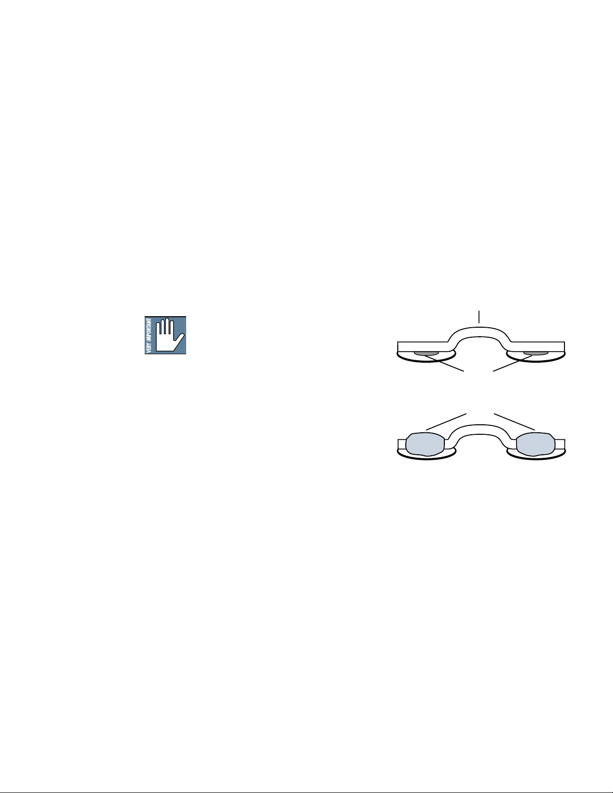
When installing jumpers, do not run their
ends through holes in the circuit board.
Rather, solder them flat against the desired
pad (the flat silver area, possibly with a hole
in the middle). Make sure the ends of these
flat wires do not extend beyond the pad.
Jumper
BEFORE
Holes
AFTER
Solder
Mackie Disclaimer
Any modification of any Mackie product
must be performed by a competent electronic
technician. LOUD Technologies accepts no
responsibility for any damages or injuries
caused by any modification, regardless of the
source of the modification instructions or the
qualifications of the technician performing
them. In the case of such damages, LOUD
Technologies may declare warranty privileges
void. BE CAREFUL!
2
Page 3
1202-VLZ PRO Modifications
Pre-Fader Mod (Aux To Monitor)
This modification changes AUX SEND 2 to
be
pre-fader, pre-mute
mute
. (“fader” refers to the channel GAIN
knob, and “mute” refers to the channel’s
MUTE/ALT 3-4 switch.) In order to convert
the entire mixer, it must be done on each
channel. Is slightly more involved for the stereo channels 5–12. The work area is on the
underside of the circuit board, near the channel AUX SEND knobs.
1. Remove all cords, including the power
cable, from the 1202-VLZ PRO.
2. Place the mixer upside-down on a dry,
non-marring surface.
3. Remove the screws that attach the bot-
tom cover. Keep track of what screws go
where. Remove the bottom cover.
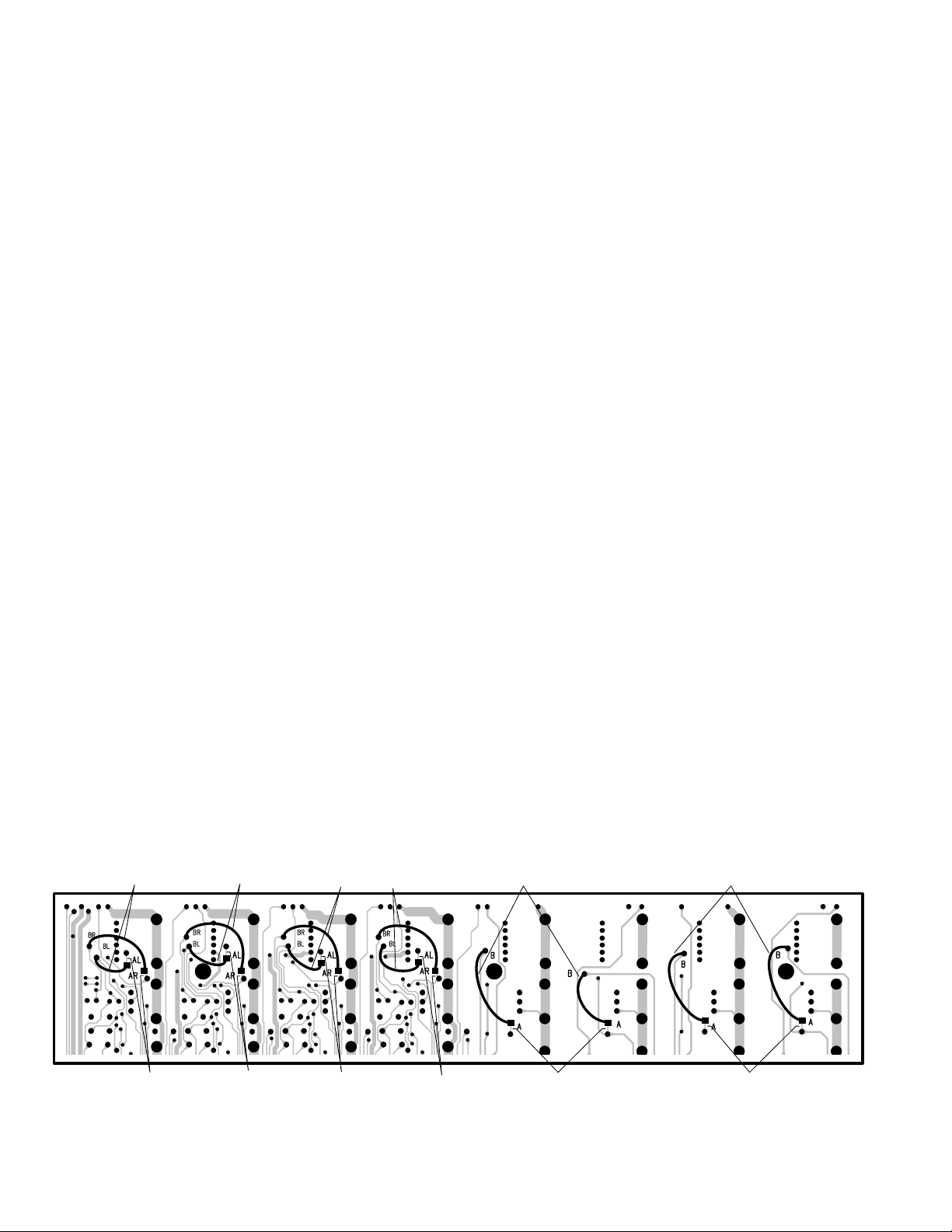
4. Using a sharp “X-acto” type knife, cut the
conductor at point ‘A’ (channels 1–4) or
the conductors at points ‘AL’ and ‘AR’
(channels 5–12). Be careful to cut all the
way through the conductor, and do not
cut any nearby traces.
5. Add a jumper from point ‘B’ to the
square pad at point ‘A’ (channels 1–4) or
from points ‘BL’ to ‘AL’ and ‘BR’ to ‘AR’
(channels 5–12).
instead of
post-fader, post-
Pre-Mute Mod
This modification changes AUX SEND 1 (in
post
mode) and AUX SEND 2 to receive signal regardless of the channel’s MUTE/ALT 34 switch position, but still be
knob). In order to convert the entire mixer, it
must be done on each channel. It is slightly
more involved for the stereo channels 5
through 12. The work area is on the underside of the circuit board, near the channel
MUTE/ALT 3-4 switches.
1. Remove all cords, including the power
cable, from the 1202-VLZ PRO.
2. Place the mixer upside-down on a dry,
non-marring surface.
3. Remove the screws that attach the bot-
tom cover. Keep track of what screws go
where. Remove the bottom cover.
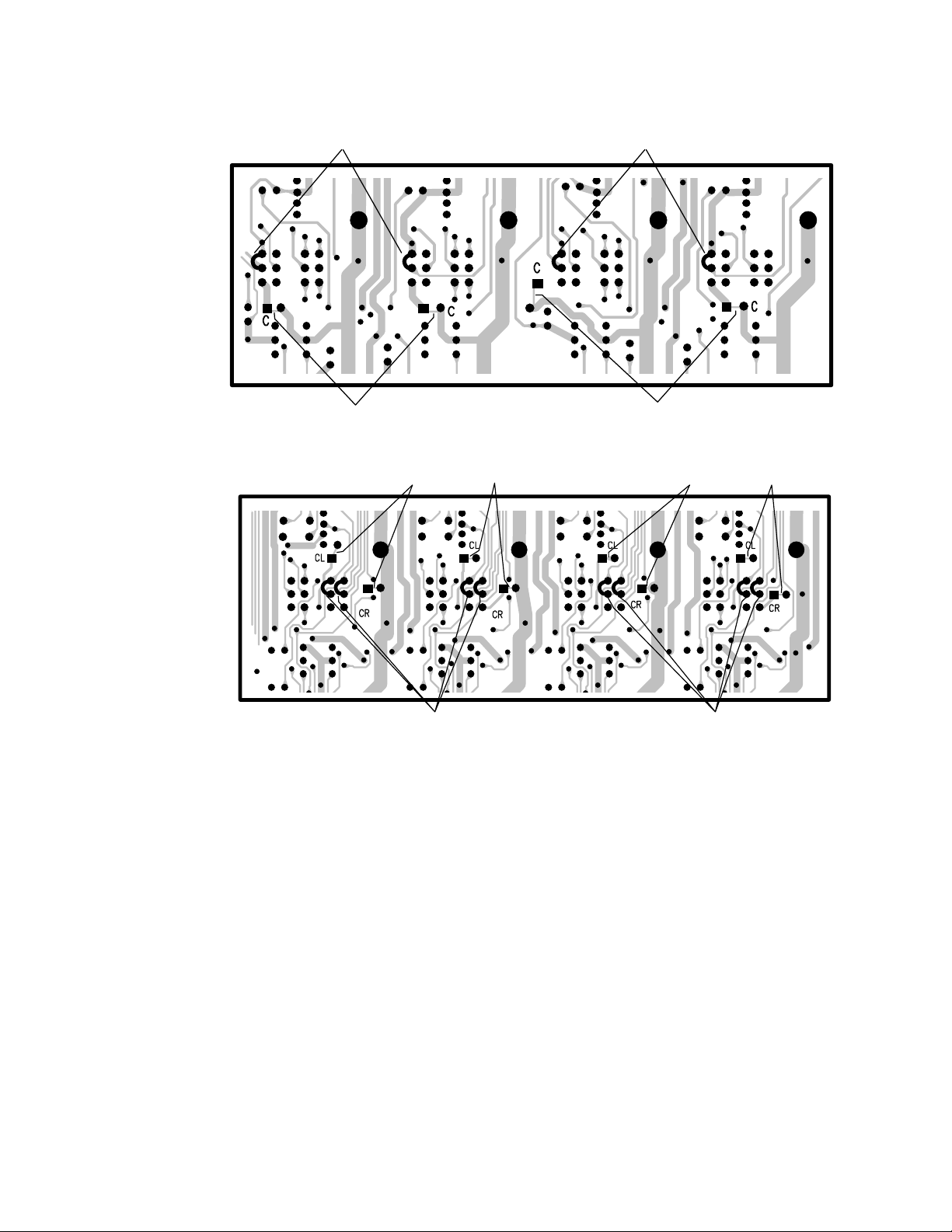
4. Using a sharp “X-acto” type knife, cut the
conductor at point ‘C’ (channels 1–4) or
the conductors at points ‘CL’ and ‘CR’
(channels 5–12). Be careful to cut all the
way through the conductor, and do not
cut any nearby traces.
5. Locate the 12 pins that comprise the
underside of each MUTE/ALT 3-4 switch.
6. Add jumpers as shown in the illustration
on the next page—they’re not marked on
the circuit board itself, so be careful.
post-fader
(GAIN
6. Repeat for all channels.
7. Check your work very carefully, then put
the bottom cover back the way you found
it. You’re done!
JUMPERS JUMPERS JUMPERS
Pre-Fader Mod
JUMPERS
3
7. Repeat for all channels.
8. Check your work very carefully, then put
the bottom cover back the way you found
it. You’re done!
JUMPERS
CUTCUTCUTCUTCUTCUT
Page 4
Channels 1-4
JUMPERS
CUT HERE CUT HERE
JUMPERS
Channels 5-12
CUT HERE
JUMPERS
Pre-Mute Mod
CUT HERE
JUMPERS
4
Page 5
Main Mix Source Mod
This modification changes the SOURCE
matrix’s MAIN MIX selection to tap the stereo signal before the MAIN MIX level control ( pre ) instead of after ( post ). This could be
especially handy for live work
where the engineer wants to be able to cotrol
the MAIN MIX level (sent to the house system) without changing the level in his headphones. The work area is on the underside of
the circuit board, near the MAIN MIX level
control.
Caution:
meters to indicate pre MAIN MIX levels.
They will no longer indicate the signal level at
the MAIN OUTS, but rather the signal level
at the PHONES and CONTROL ROOM
outputs (when MAIN MIX SOURCE is
selected).
This modification also causes the
1. Remove all cords, including the power
cable, from the 1202-VLZ PRO.
2. Place the mixer upside-down on a dry,
non-marring surface.
3. Remove the screws that attach the bottom cover. Keep track of what screws go
where. Remove the bottom cover.
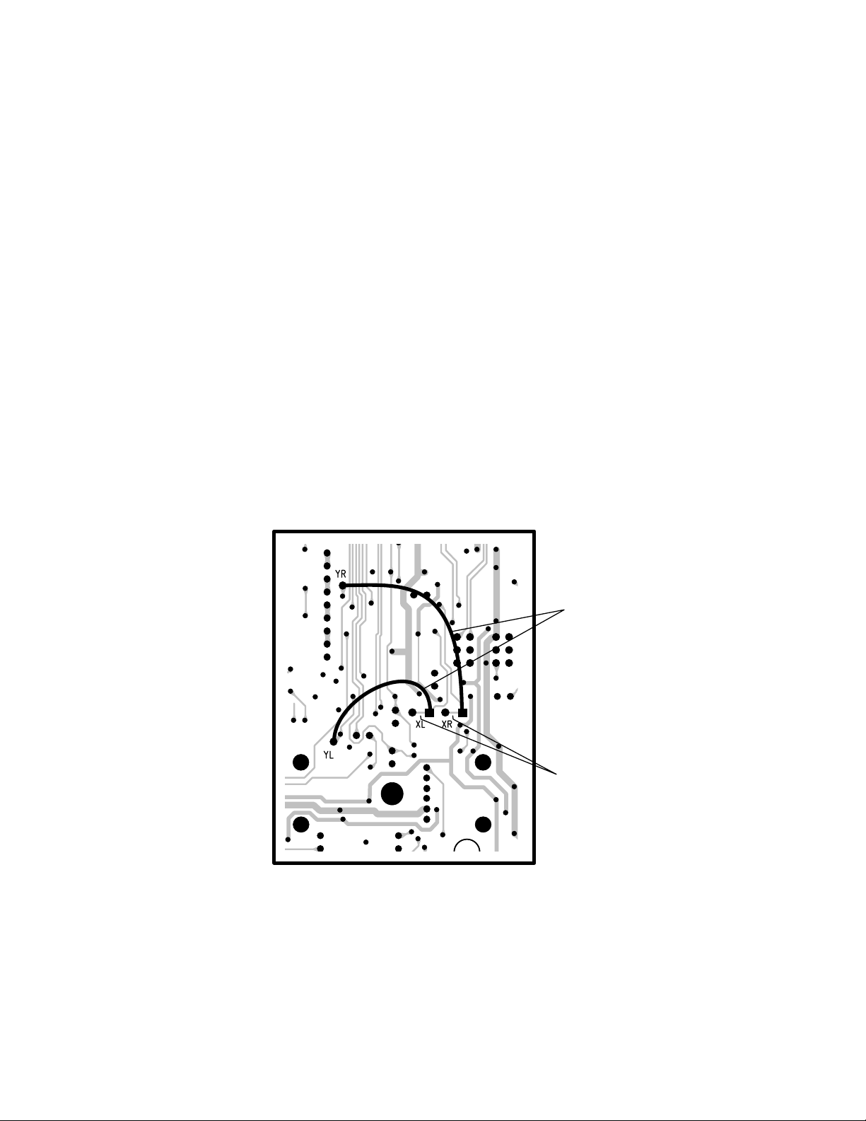
4. Using a sharp “X-acto” type knife, cut the
conductor at points ‘XL’ and ‘XR’. Be
careful to cut all the way through the
conductor, and do not cut any nearby
traces.
5. Add a jumper from point ‘YL’ to the
square pad at point ‘XL’ and from point
‘YR’ to the square pad at point ‘XR’.
6. Check your work very carefully, then put
the bottom cover back the way you found
it. You’re done!
JUMPERS
HERE
CUT
HERE
5
Page 6

1402-VLZ PRO Modifications
Pre-Fader Mod (Aux To Monitor)
This modification changes AUX SEND 2 to
be pre-fader, pre-mute instead of post-fader, post-
mute. (“Mute” refers to the channel’s MUTE/
ALT 3–4 switch.) In order to convert the
entire mixer, it must be done on each channel, and is slightly more involved for the stereo channels 7–14. The work area is on the
underside of the circuit board, near the channel AUX SEND knobs.
1. Remove all cords, including the power
cable, from the 1402-VLZ
2. Place the mixer upside-down on a dry,
non-marring surface.
PRO.
Channels 1-6
JUMPERS
HERE
5
JUMPERS
HERE
3. Remove the screws that attach the bottom cover. Keep track of what screws go
where. Remove the bottom cover.
4. Using a sharp “X-acto” type knife, cut the
conductor at point ‘A’ (channels 1–6) or
the conductors at points ‘AL’ and ‘AR’
(channels 7–14). Be careful to cut all the
way through the conductor, and do not
cut any nearby traces.
5. Add a jumper from point ‘B’ to the
square pad at point ‘A’ (channels 1–6) or
from points ‘BL’ to ‘AL’ and ‘BR’ to ‘AR’
(channels 7–14).
6. Repeat for all channels.
7. Check your work very carefully, then put
the bottom cover back the way you found
it. You’re done!
5
JUMPERS
HERE
5
CUT
HERE
4
Channels 7-14
JUMPERS
HERE
CUT
HERE
6
HERE
5
4
CUT
CUT
HERE
4
JUMPERS
HERE
CUT
HERE
CUT
HERE
4
Page 7

Pre-Mute Mod
This modification changes AUX SEND 1 (in
post mode) and AUX SEND 2 to receive signal
regardless of the channel’s MUTE/ALT 3–4
switch position, but still be
to convert the entire mixer, it must be done
on each channel, and is slightly more involved
for the stereo channels 7–14. The work area is
on the underside of the circuit board, near the
channel MUTE/ALT 3–4 switches.
1. Remove all cords, including the power
cable, from the 1402-VLZ
2. Place the mixer upside-down on a dry,
non-marring surface.
3. Remove the screws that attach the bottom cover. Keep track of what screws go
where. Remove the bottom cover.
post-fader . In order
PRO.
Channels 1-6
JUMPERS
HERE
6 6
JUMPERS
HERE
4. Using a sharp “X-acto” type knife, cut the
conductor at point ‘C’ (channels 1–6) or
the conductors at points ‘CL’ and ‘CR’
(channels 7–14). Be careful to cut all the
way through the conductor, and do not
cut any nearby traces.
5. Locate the 12 pins that comprise the
underside of each MUTE/ALT 3–4 switch.
6. Add jumpers as shown on the illustration
below—they’re not specifically marked on
the circuit board itself, so be careful.
7. Repeat for all channels.
8. Check your work very carefully, then put
the bottom cover back the way you found
it. You’re done!
JUMPERS
HERE
6
CUT
HERE
JUMPERS
HERE
4
CUT
HERE
CUT
HERE
Channels 7-14
JUMPERS
7
4
HERE
CUT
HERE
44
CUT
HERE
66
4
Page 8

Main Mix Source Mod
This modification changes the SOURCE
matrix’s MAIN MIX selection to tap the stereo signal before the MAIN MIX level control ( pre ) instead of after ( post ). This could be
especially handy for live work where the engineer wants to be able to control the MAIN
MIX level (sent to the house system) without
changing the level in his headphones. The
work area is on the underside of the circuit
board, near the MAIN MIX level control.
Caution:
meters to indicate pre MAIN MIX levels.
They will not longer indicate the signal level
at the MAIN OUTS, but rather the signal
level at the PHONES and CONTROL
ROOM outputs (when MAIN MIX
SOURCE is selected).
1. Remove all cords, including the power
2. Place the mixer upside-down on a dry,
This modification also causes the
cable, from the 1402-VLZ
non-marring surface.
PRO.
5. Add a jumper from point ‘YL’ to the
square pad at point ‘XL’ and from point
‘YR’ to the square pad at point ‘XR’.
6. Check your work very carefully, then put
the bottom cover back the way you found
it. You’re done!
3. Remove the screws that attach the bottom cover. Keep track of what screws go
where. Remove the bottom cover.
4. Using a sharp “X-acto” type knife, cut the
conductor at points ‘XL’ and ‘XR’. Be
careful to cut all the way through the
conductor, and do not cut any nearby
traces.
CUT
HERE
JUMPERS
HERE
4
5
8
Page 9

1604-VLZ PRO Modifications
1604-VLZ
This changes AUX SENDS 1 and 2 , with the
pre switch engaged, to receive their signals
EQ instead of pre- EQ . The signal remains post-
low cut, pre-mute and pre-fader. With the pre
switch disengaged (up), the signals are not
affected by the mod. The following must be performed for each channel you wish to modify:
1. Remove all cords, including the power
cable, from the 1604-VLZ
2. Place the mixer upside-down on a dry,
non-marring surface.
3. If you have converted your mixer to the
rack-mount position or have installed a
RotoPod, undo those changes and temporarily configure the mixer in the original
desktop mode. You do not have to install
the pod, just get it out of the way of the
bottom cover.
PRO Post-EQ Mod
PRO.
post-
4. Remove the screws that attach the bottom cover. Keep track of what screws go
where. Remove the bottom cover.
5. Cut the conductor at point C, between
the square and round pads. Be careful to
cut all the way through the conductor,
and do no cut any nearby traces. Each
channel is slightly different, but this
graphic shows Channel 16, which is very
different from the others, and Channel
15 (respectively), which is similiar to the
remaining channels.
6. Add a jumper from the square pad at
point B to the square pad at point C.
7. Repeat for each channel you wish to
modify.
8. Check your work very carefully, them put
the bottom cover back the way you found
it. You’re done!
CUT
HERE
5
JUMPERS
HERE
6
Channel 16
Channel 15
9
Page 10

1604-VLZ
PRO Source Mod
This changes the CTL ROOM/PHONES
level control in the SOURCE matrix to
receive the main mix stereo signal pre- MAIN
MIX fader instead of post- MAIN MIX fader.
You can accomplish the same result that this
modification provides by using two standard
1
⁄
" tip-sleeve “jumper cables” plugged into
4
the MAIN INSERT ( L and R ) to the first click
and the other end plugged into STEREO
AUX RETURN 4
ONLY. STEREO AUX RETURN 4
control the volume as well as
PHONES
You can also use the
RCA jacks (you will need
, assigned to
level control.
TAPE INPUT (L
C-R/PHNS
level will
CTL ROOM/
and R)
1
⁄
" to RCA cables
4
or adapters) and assign the TAPE source button in the
SOURCE
matrix.
1. Remove all cords, including the power
cable, from the 1604-VLZ
PRO.
2. Undo the PHONES nut.
3. Place the mixer upside-down on a dry,
non-marring surface.
4. If you have converted your mixer to the
rack-mount position or have installed a
RotoPod, undo those changes and temporarily configure the mixer in the original
desktop mode. You do not have to install
the pod, just get it out of the way of the
bottom cover.
5. Remove the screws that attach the bottom cover. Keep track of what screws go
where. Remove the bottom cover.
6. Move the PHONES board to one side so
you can get to points YL and YR marked
on the board.
7. Cut the conductor at points ZL and ZR,
between the square and round pads. Be
careful to cut all the way through the
conductor, and do no cut any nearby
traces.
8. Add a jumper from the square pad at
point YL to the square pad at point ZL
and another from the square pad at point
YR to the square pad at point ZR.
9. Check your work very carefully, then put
the Phono board and nut, and bottom
cover back the way you found them.
You’re done!
10
JUMPERS
HERE
8
CUT
HERE
7
Page 11

8•Bus Modifications
AUX Send Mod
This modification changes the tap point of all
“pre” AUX sends from post -EQ to pre -EQ. It
must be done on each channel. For example,
if you have a 24•8, the modification must be
done on all 24 input channels.
See Figure below. This modification takes
place on each channel strip in an area under
the AUX 1/2 Pre/Post switch.
1. Remove power cable.
2. Cut the conductor at Point A.
3. Add a jumper at Point B.
4. Repeat for all input channels.
PFL Mod
This modification changes the tap point of
the SOLO bus from
reo) to
done on each channel. For example, if you
have a 24•8, the modification must be done
on all 24 input channels.
See Figure below. This modification takes
place on each channel strip in an area under
the channel fader.
1. Remove power cable.
2. Cut the conductor at Point C.
3. Cut the conductor at Point D.
4. Add a jumper at Point E.
5. Add another jumper at Point F.
pre
-fader/
post
-fader/
pre
-mute (mono). It must be
post
-mute (ste-
BEFORE
cut here (A)
AFTER
add jumper (B)
6. Repeat for all input channels.
BEFORE
AFTER
cut here (C&D)
add jumpers
(E&F)
Aux Send Modification
11
PFL Modification
Page 12

BEFORE
cut here (G)
AFTER
add jumper (H)
Mix-B Mute Modification
Mix-B Source Mod
This modification changes the tap point of
the Mix-B Source switch (engaged) from pre fader/ pre -mute to post -fader/ post -mute. It
must be done on each channel. For example,
if you have a 24•8, the modification must be
done on all 24 input channels.
See Figure below. This modification takes
place on each channel strip in an area under
the Mix-B Source switch.
1. Remove power cable.
2. Cut the conductor at Point G.
3. Add a jumper at Point H.
4. Repeat for all input channels.
Mix-B Mute Mod
This modification converts the Mix-B Source
switch to a Mix-B MUTE switch. The switch
will no longer be able to source the channel
signal. This modification must be done on
each channel. For example, if you have a
24•8, the modification must be done on all
24 input channels.
See Figures below. This modification takes
place on each channel strip in an area under
Mix-B Source switch.
1. Remove power cable.
2. Cut the conductor at Point G.
3. Add Jumper to point H.
4. Repeat for all input channels.
BEFORE
cut here (G)
AFTER
add jumper (H)
Mix-B Source Modification
12
Page 13

The infamous and dreaded but-if-we-hadn’t-included-it
-we’d-just-have-to-fax-it-to-the-foolhardy-anyway
modification
BEFORE
AFTER
(AUX SEND 1&2)
PRE SWITCH
(AUX SEND 3&4/5/6)
PRE SWITCH
(L)
(K)
(K)
(L)
add jumper (B)
add jumper (D)
cut here (A)
(P) (P)
(Q)(Q)
AUX 1/2 Source Mod
This modification should only be
performed if the console is being
used strictly for recording.
A. When the Aux 1/2 Pre Switch is engaged,
Aux Send 1 and 2 will tap the Pre-Fader
information from the tape returns.
13
Page 14

B. When the Aux 1/2 Pre Switch is not
engaged, Aux Send 1 and 2 function normally, as post fader channel sends.
All that said, here’s the mod.
See Figure above. This modification takes
place on each channel strip in the area
under the AUX 3/4 Mix-V Source switch
and also under and near the AUX 1/2
PRE switch.
1. Remove power cord.
2. Cut two (2) traces at point (A).
Note: The wire used in the next three
steps should be 24-28 gauge insulated
jumper wire.
Do not strip off any more insulation than
is absolutely necessary.
3. Add a 1-1/2” jumper (B), connected at
points K and L.
4. Add a 2-1/4” jumper (D), connected at
points P and Q.
14
Page 15

“Mackie.” and the “Running Man” figure are
registered trademarks of LOUD Technologies
Inc.
©2003 LOUD Technologies Inc.
All Rights Reserved.
15
Page 16

LOUD Technologies Inc.
16220 Wood-Red Road NE • Woodinville, WA 98072 • USA
US and Canada: 800.898.3211
Europe, Asia, Central and South America: 425.487.4333
Middle East and Africa: 31.20.654.4000
Fax: 425.487.4337 • www.mackie.com
E-mail: sales@mackie.com
16
 Loading...