

Page 1
CFX series
Page 3 is interactive
Go To Bulletins
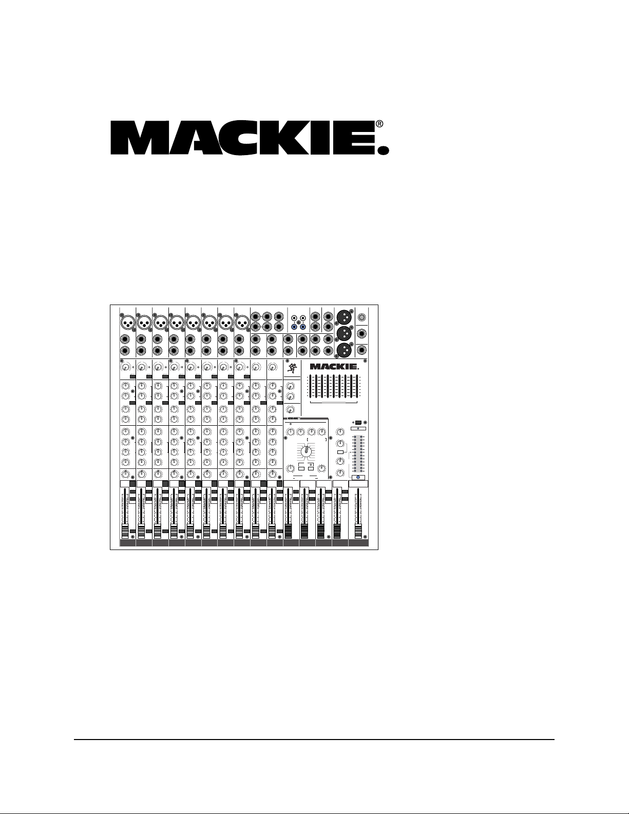
Compact Effects Mixers:
CFX•12, CFX•16 and CFX•20
MAIN OUT
MAIN INSERT
MIC
3
MIC
MIC
2
MIC
1
BAL/UNBAL
BAL/UNBAL
LINE IN
LINE IN
INSERT
INSERT
1
2
U
U
G
G
A
A
C
C
I
I
I
I
N
N
M
M
ZERO
ZERO
6
6
+50
+50
LEVEL
LEVEL
-15dB+30dB
-15dB+30dB
TRIM
TRIM
LOW CUT
LOW CUT
100 Hz
100 Hz
AUX
AUX
U
U
1
1
+15
+15
OO
OO
U
U
2
2
+15
+15
OO
OO
PRE FADER
PRE FADER
U
U
EFX
EFX
1
1
(EXT)
(EXT)
+15
+15
OO
OO
U
U
EFX
EFX
2
2
(INT)
(INT)
+15
+15
OO
OO
EQ
EQ
U
U
HI
HI
12k
12k
-15
-15
+15
+15
U
U
MID
MID
-15
-15
+15
+15
600
600
FREQ
FREQ
1.5k150
1.5k150
8k100
8k100
U
U
LOW
LOW
80Hz
80Hz
-15
-15
+15
+15
PANLRPANLRPANLRPANLRPANLRPANLRPANLRPANLRPANLRPAN
LR
1
2
ASSIGN
ASSIGN
MUTE
MUTE
dB
dB
10
10
-
2
-
1
1
5
5
3-4
3-4
U
U
5
5
10
10
20
20
30
30
40
40
SOLO
SOLO
50
50
PFL
PFL
60
60
OO
OO
4
MIC
BAL/UNBAL
BAL/UNBAL
BAL/UNBAL
LINE IN
LINE IN
INSERT
INSERT
3
4
U
G
A
C
I
M
6
+50
-15dB+30dB
TRIM
LOW CUT
100 Hz
U
+15
OO
U
+15
OO
PRE FADER
U
+15
OO
U
+15
OO
U
-15
+15
U
-15
+15
600
U
-15
+15
3
ASSIGN
dB
10
2
5
U
5
10
20
30
40
50
60
OO
U
U
G
G
A
A
C
C
I
I
I
I
N
N
M
M
ZERO
ZERO
6
6
+50
+50
LEVEL
LEVEL
-15dB+30dB
-15dB+30dB
TRIM
TRIM
LOW CUT
LOW CUT
100 Hz
100 Hz
AUX
AUX
U
U
1
1
+15
+15
OO
OO
U
U
2
2
+15
+15
OO
OO
PRE FADER
PRE FADER
U
U
EFX
EFX
1
1
(EXT)
(EXT)
+15
+15
OO
OO
U
U
EFX
EFX
2
2
(INT)
(INT)
+15
+15
OO
OO
EQ
EQ
U
U
HI
HI
12k
12k
-15
-15
+15
+15
U
U
MID
MID
-15
-15
+15
+15
600
600
FREQ
FREQ
1.5k150
1.5k150
8k100
8k100
U
U
LOW
LOW
80Hz
80Hz
-15
-15
+15
+15
4
5
ASSIGN
ASSIGN
MUTE
MUTE
dB
dB
10
10
-
2
-
2
1
1
5
5
3-4
3-4
U
U
5
5
10
10
20
20
30
30
40
40
SOLO
SOLO
50
50
PFL
PFL
60
60
OO
OO
MIC
7
MIC
5
MIC
6
BAL/UNBAL
LINE IN
LINE IN
INSERT
INSERT
5
6
U
G
A
C
I
I
I
N
N
M
ZERO
ZERO
6
+50
LEVEL
LEVEL
-15dB+30dB
TRIM
LOW CUT
100 Hz
AUX
AUX
U
1
1
+15
OO
U
2
2
+15
OO
PRE FADER
U
EFX
EFX
1
1
(EXT)
(EXT)
+15
OO
U
EFX
EFX
2
2
(INT)
(INT)
+15
OO
EQ
EQ
U
HI
HI
12k
12k
-15
+15
U
MID
MID
-15
+15
600
FREQ
FREQ
1.5k150
1.5k150
8k100
8k100
U
LOW
LOW
80Hz
80Hz
-15
+15
6
ASSIGN
MUTE
MUTE
dB
10
-
2
-
1
1
5
3-4
3-4
U
5
10
20
30
40
SOLO
SOLO
50
PFL
PFL
60
OO
8
LR
BAL/UNBAL
BAL/UNBAL
LINE IN
LINE IN
INSERT
INSERT
7
8
U
U
G
G
A
A
C
C
I
I
I
I
N
N
M
M
ZERO
ZERO
6
6
+50
+50
LEVEL
LEVEL
-15dB+30dB
-15dB+30dB
TRIM
TRIM
LOW CUT
LOW CUT
100 Hz
100 Hz
AUX
AUX
U
U
1
1
+15
+15
OO
OO
U
U
2
2
+15
+15
OO
OO
PRE FADER
PRE FADER
U
U
EFX
EFX
1
1
(EXT)
(EXT)
+15
+15
OO
OO
U
U
EFX
EFX
2
2
(INT)
(INT)
+15
+15
OO
OO
EQ
EQ
U
U
HI
HI
12k
12k
-15
-15
+15
+15
U
U
MID
MID
-15
-15
+15
+15
600
600
FREQ
FREQ
1.5k150
1.5k150
8k100
8k100
U
U
LOW
LOW
80Hz
80Hz
-15
-15
+15
+15
7
8
ASSIGN
ASSIGN
MUTE
MUTE
dB
dB
10
2
5
U
5
10
20
30
40
50
60
OO
dB
10
10
-
2
-
2
1
1
5
5
3-4
3-4
U
U
5
5
10
10
20
20
30
30
40
40
SOLO
SOLO
50
50
PFL
PFL
60
60
OO
PRE FADER
9-10
ASSIGN
OO
STEREO EFX
U
TRIM
U
OO
U
OO
U
OO
U
OO
U
-15
U
-15
U
-15
U
-15
+20-20
+15
+15
+15
+15
+15
+15
+15
+15
RETURN
1
2
(MONO) (MONO)
9
LEFT
RIGHT
10
9
10
AUX
1
2
EFX
1
(EXT)
EFX
2
(INT)
EQ
HI
12k
HI
MID
3k
LOW LOW
MID
400Hz
LOW
80Hz
MUTE
dB
10
-
2
1
5
3-4
U
5
10
20
30
40
SOLO
50
PFL
60
EFX SEND
11
LEFT
RIGHT
12
11
U
12
+20-20
TRIM
AUX
U
1
+15
OO
U
2
+15
OO
PRE FADER
U
EFX
1
(EXT)
+15
OO
U
EFX
2
(INT)
+15
OO
EQ
U
HI
12k
-15
+15
U
HI
MID
3k
-15
+15
U
MID
400Hz
-15
+15
U
LOW
80Hz
-15
+15
11- 12
ASSIGN ASSIGN
MUTE
-
2
1
3-4
SOLO
PFL
OO
TAPE
INPUT
1
L
RLR
2
MASTER SEND
U
+15
OO
U
+15
OO
U
+15
OO
DIGITAL STEREO EFFECTS PROCESSOR
CLIP
U
+15
OO
EFX
2
SEND
REVERSE
GATED
CATHEDRAL
LG.HALL
MD.HALL
LG.PLATE
MD.PLATE
SM.ROOM
NORMAL NORMAL
100 100
TIME
RATE
SUB
dB
10
5
U
5
10
20
30
40
50
60
OO
MAIN OUT
TAPE
OUTPUT
LL
R
R
123
1
L
R
AUX SENDUTILITY OUT
AUX
1
2
EFX
1
(EXT)
CUSTOM 32-BIT PRECISION
EFX 2 (INT) RETURN MASTERS
U
+15
OO
TO MAIN MIX
WIDE BYPASS
CHORUS/FLANGE/PHASER
SUB
1
ASSIGN
dB
10
LEFT
5
RIGHT
U
5
10
20
30
40
50
60
OO
4
2
SUB OUT
15
10
5
0
5
10
15
1K50025063 125 16K2K 4K 8K
STEREO GRAPHIC EQ
CFX12 MIXER
12 CHANNEL COMPACT INTEGRATED LIVE SOUND MIXER
U
U
+15
OO
+15
OO
OO
EFX 1 RETURN
1
AUX
2
AUX
EFFECTS TO MONITOR
DELAY 1
DELAY 2
OO
DELAY 3
TAPE LEVEL
DELAY 4
CHORUS
BREAK SWITCH
FLANGE
(MUTES ALL CHANNELS)
PHASER
SPRING
EFX
REVERBS
DELAYS
OO
PHONES LEVEL
DAMPING
OO
DEPTH
UTILITY OUT LEVEL
SUB
SUB
2
3
ASSIGN
ASSIGN
dB
dB
10
10
LEFT
LEFT
5
5
RIGHT
RIGHT
U
U
5
5
10
10
20
20
30
30
40
40
50
50
60
60
OO
OO
LAMP
12V 0.5A
L
EFX
R
FOOT
SWITCH
S
75Hz
SUB OUT
PHONES
15
10
5
0
5
10
15
PHANTOM POWER
48v
U
POWER STATUS
LEFT RIGHT
+20
CLIP
22
U
10
7
4
+20
2
0
2
4
ZERO
LEVEL
7
SET
10
MAX
20
U
30
0dB
=
0dBu
+10
RUDE SOLO
STEREO
4
MAIN MIX
dB
10
LEFT
5
RIGHT
U
5
10
20
30
40
50
60
OO
SERVICE MANUAL
1999,2000 MACKIE DESIGNS, INC.
820-218-00
Page 2
SERVICE ON THIS EQUIPMENT IS TO BE PERFORMED BY
EXPERIENCED REPAIR TECHNICIANS ONLY
2
Page 3
CONTENTS
Click on any item to open that page
ALL BOARDS
Introduction.....................................................................3
Overview..........................................................................4
Block Diagram..................................................................5
Specifications...................................................................6
Safety test........................................................................9
Connectors.......................................................................10
Quick parts.......................................................................12
Parts...................................................................................A1
Fold-out Sections
Exploded Views
CFX•12.........................................................................B1
CFX•16.........................................................................C1
CFX•20.........................................................................D1
Schematics and PCB layouts
Effects board....................................................................192-1
Master board...................................................................241-1
Slave 4 board...................................................................242-1
Power supply board........................................................258-1
AC power supply.............................................................260-1
INTRODUCTION
SERVICE ON THIS EQUIPMENT IS TO BE PERFORMED BY
EXPERIENCED REPAIR TECHNICIANS ONLY
This manual contains basic service information. It is essential that you have a copy of the
user’s manual as this contains the complete operating instructions.
SERVICE TECHNICAL ASSISTANCE
Mackie Designs, Service Technical Assistance, is available 8AM - 5PM PST, Monday through
Friday for Authorized Mackie Service Centers, at 1-800-258-6883. Feel free to call with any
questions and speak with a carefully-calibrated technician. If one is not available, leave
a detailed message and a qualified Mackoid will return your call asap.
DISCLAIMER
The information contained in this manual is proprietary to Mackie Designs, Inc. The entire
manual is protected under copyright and may not be reproduced by any means without
express written permission from Mackie Designs, Inc.
3
Page 4
Overview
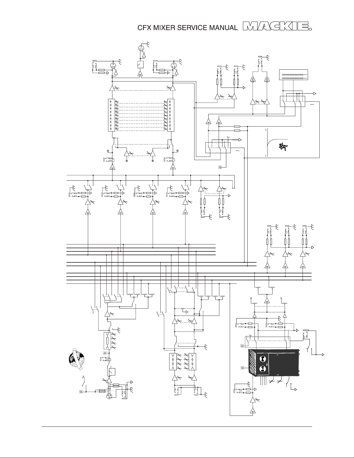
The CFX mixer series consists of 3 models: the CFX•12, CFX•16 and CFX•20. Each consists
of five circuit boards: Effects, Master, Slave, Power and AC Power.
The Master board is the main mixer circuit.
The Effects board is fitted on the back of the Master board. This is exactly the same as
used in the PPM Professional Powered Mixer series.
The Slave board connects to the left of the Master board and adds four channels. The
CFX•12 has one Slave board, the CFX•16 has two, and the CFX•20 has three. This is the
main difference between the three models.
The power board regulates the AC power to +/- 15VDC, +5VDC and +48VDC (phantom
power).
The AC power board holds the IEC connector, fuse holder, power switch and caps.
This table shows which boards are used in each mixer.
Note: Each schematic chapter is labeled with the number of the board it describes. For
example, chapter 241 contains schematics and pcb layouts for circuit board number
550-241-00, chapter 192 is for circuit board 550-192-00.
MODEL EFFECTS MASTER SLAVE POWER AC POWER
CFX•12 192 241 242 (QTY 1) 258 260
CFX•16 192 241 242 (QTY 2) 258 260
CFX•20 192 241 242 (QTY 3) 258 260
4
Page 5
TAPE OUT
LEFT
1
2
BREAK
MAIN OUT
LEFT
3
8K 16K
4K
2K
500 1K
250
63 125
MAIN
LEVEL
OUT
SUBWOOFER
1
2
3
MAIN OUT
RIGHT
MAIN
LEVEL
1
2
3
UTILITY OUT LEFT
8K 16K
4K
2K
500 1K
250
63 125
BREAK
PFL
TAPE OUT
RIGHT
SIGNAL
TO PHONES
UTILITY OUT RIGHT
UTILITY
LEVEL
+5
VDC
SOLO
OFF
LPF
75 Hz
TAPE
LEVEL
SOLO
PHONES
221074202471020
PHONES LEVEL
PFL
METER
SIGNAL
TO LEFT
PFL
ON
EXIT
WOODINVILLE
BOTHELL MONROE
30
ON
OFF
SOLO
SOLO
SOLO CONTROL
(ACTIVE LOW)
MAIN
RIGHT
MAIN
LEFT
SUB 4
SUB 3
SUB 2
SUB 1
CONTROL
SOLO
SOLO
AUX 1
AUX 2
EFX 1
EFX 2
SUB 1 OUT
LEFT
ASSIGN
TAPE IN
EFX 2
RIGHT
RIGHT
SOLO
MAIN INSERT
ASSIGN
SUB 4 OUT
LIGHT
RUDE SOLO
LEFT
ASSIGN
RIGHT
ASSIGN
EFX RETURN 1
STEREO EFX
STEREO EFX
RETURN 1 LEFT
3-4
1-2
PAN
MAIN
MUTE
3K
MID HI
LO MID
80 800 12K
LEFT
TRIM
LINE IN
STEREO
3K
MID HI
LO MID
80 800 12K
CHANNELS
RIGHT
RETURN 1 RIGHT
AUX 1
AUX 2
EFX 1
EFX 2
PRE/POST
SOLO CONTROL
FROM EFX
TO MAIN MIX
STEREO EFX
RETURN 2 LEFT
EFX BYPASS
EFX LEVEL SET
EFX SEND 2
(ACTIVE LOW)
EFX SEND 1
TIME/RATE
AUX SEND 1
EFX TO AUX 2
TO RIGHT MAIN
EMAC
DAMPING/DEPTH
AUX SEND 2
R
DSP
EFX WIDE
AUX SEND 2
EFX SEND 1
EFX
FOOT
SWITCH
EFX BYPASS
TO LEFT MAIN
EFX TO MAIN MIX
+5
VDC
L
AUX SEND 1
EFX TO AUX 1
STEREO EFX
RETURN 2
RIGHT
EFX
SELECT
EFX SEND 2
MAIN INSERT
LEFT
ASSIGN
RIGHT
ASSIGN
SUB 2 OUT
1-2
PAN
SOLO
MUTE
MID FREQHI
W
O
P
M
O
T
N
A
H
P
L
A
B
O
L
G
+48 VDC
LO
SET
LEVEL
INSERT
LOW CUT
TRIM
PHANTOM POWER
2
1
TAPE IN
LEFT
LEFT
ASSIGN
RIGHT
ASSIGN
SUB 3 OUT
EFX 1
AUX 1
AUX 2
3-4
PRE-P0ST
FADER
80 12K
100 Hz
HPF
3
MIC/LINE IN
MONO CHANNELS
Block Diagram
5
Page 6

Specifications
Frequency Response
Mic Input to any Output (Trim at
0 dB):
+0, –1 dB, 32Hz to 20kHz
Distortion THD and SMPTE
IMD; 20Hz to 20kHz
Mic Input to Main Output:
< 0.05% @ +4 dBu output
Noise
20Hz to 20kHz BandWidth
Ω Ω
(150
Ω source impedance)
Ω Ω
Equivalent Input Noise (EIN):
–127 dBu
Residual Output Noise:
Main, Monitor, & Effects out-
puts
Channel & Master levels off
–95 dBu
Common Mode Rejection
Ratio (CMRR)
60 dB @ 1kHz, Trim @ 0 dB
Crosstalk
Adjacent Inputs or Input to Output:
–90 dB @ 1kHz
Fader Off
–90 dB @ 1kHz
Mute Switch and Break Switch
Mute
–80 dB @ 1kHz
Input Level Trim Control
Range
+6 to –50 dB
Phantom Power
+48V DC
Equalization
Low Cut: 100Hz, –18 dB/octave
Mono Channel EQ:
High ±15 dB @ 12kHz
Mid ±15 dB @ 100Hz
Low ±15 dB @ 80Hz
Stereo Channel EQ:
High ±15 dB @ 12kHz
High Mid ±15 dB @ 3kHz
Low Mid ±15 dB @ 400Hz
Low ±15 dB @ 80Hz
Graphic EQ (9 bands):
Q = 1.414, ISO octave centers
±15 dB @ 63, 125, 250, 500, 1k,
2k, 4k, 8k, 16k Hz
Mixer Rated Output
Main, Sub, Aux, & Efx: +4 dBu
Max Rated Output: +20 dBu
Maximum Input Levels
Mic Input: –28 dBu, Trim @ +50 dB
+18 dBu, Trim @ +6 dB
Line Input: –8 dBu, Trim @ +30 dB
+38 dBu, Trim @ -15 dB
Insert Input, Stereo Line Input,
Tape Input, and
Effects Return: +20 dBu
Maximum Voltage Gain
Mic Input to
Insert Output: 50 dB
Tape Output: 66 dB
Sub Output: 66 dB
Main Output: 76 dB
Aux Send: 71 dB
Line Input to
Insert Output: 30 dB
Tape Output: 46 dB
Sub Output: 46 dB
Main Output: 56 dB
Aux Send: 51 dB
Stereo Line Input to
Tape Output: 40 dB
Sub Output: 40 dB
Main Output: 50 dB
Aux Send: 45 dB
Tape Input to
Main Output: 30 dB
Effects Return to
Main Output: 30 dB
Input Impedance
Mic Input: 3kΩ, bal
Line Input: 40kΩ, bal
Insert Input, Stereo Line Input,
Tape Input, and Effects Returns:
10kΩ, unbal
Output Impedance
Main Output, Insert Output, Tape
Output, Sub Output, and Effects
Sends: 150Ω
Digital Effects
Resolution: 16-bit, 2-channel
No. of Presets: 16
Channel Level Set LED
(Sensitivity)
0 dBu (normal operating level)
VU Meters
Main L/R
12 segments:
Clip, +10, +7, +4, +2, 0, –2, –4, –7,
–10, –20, –30
Disclaimer
Since we are always striving to
make our products better by incorporating new and improved
materials, components, and manufacturing methods, we reserve the
right to change these specifications at any time without notice.
6
Page 7
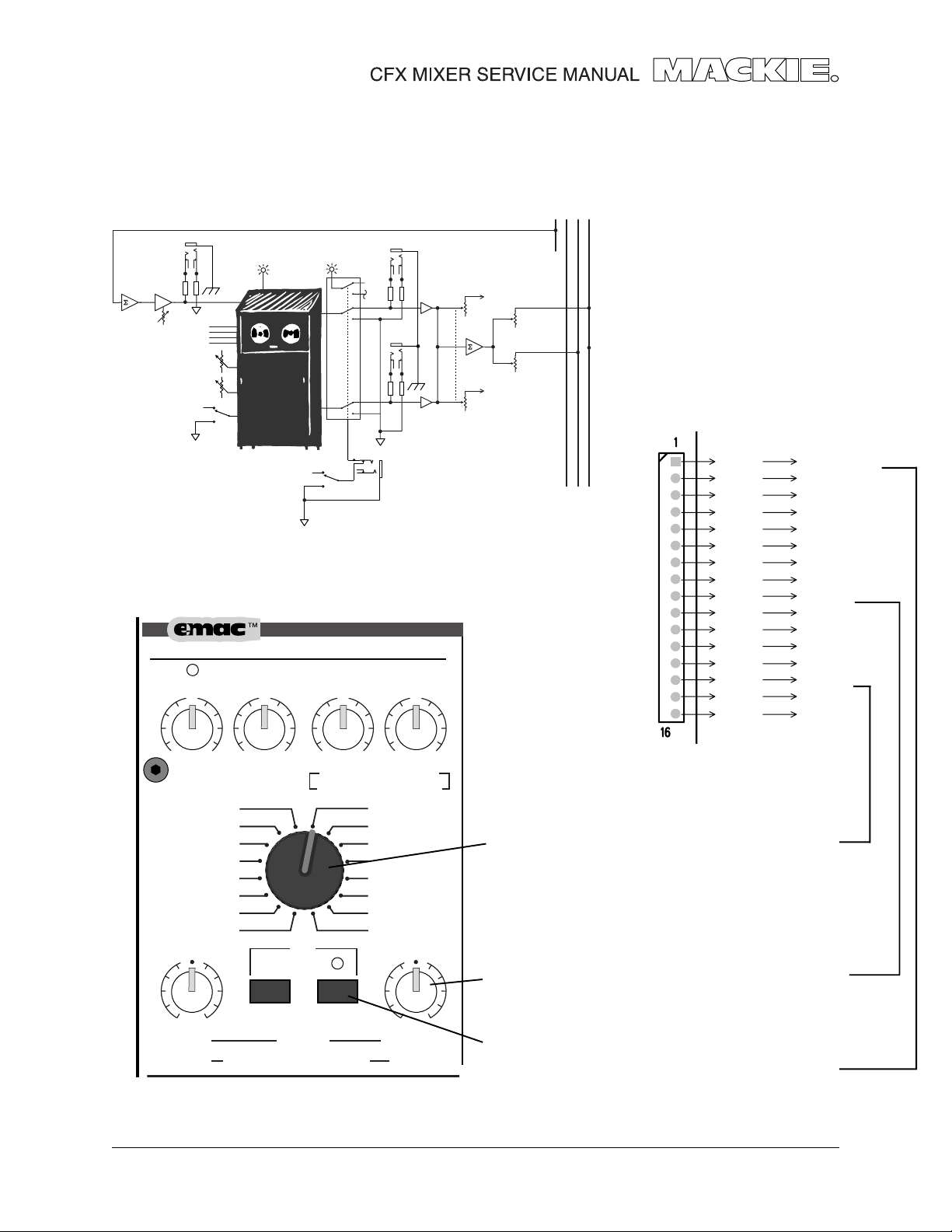
Effects board
BLOCK DIAGRAM
EFX SEND 2
EFX LEVEL SET
EFX BYPASS
STEREO EFX
RETURN 2 LEFT
EFX 2
EFX 1
AUX 2
AUX 1
EFX SEND 2
EFX
SELECT
TIME/RATE
DAMPING/DEPTH
EFX WIDE
EFX CONTROLS
DIGITAL STEREO EFFECTS PROCESSOR
CLIP
EFX 2 (INT) RETURN MASTERS
U
+5
VDC
L
STEREO EFX
RETURN 2
RIGHT
EMAC
DSP
CUSTOM 32-BIT PRECISION
U
EFX BYPASS
R
EFX
FOOT
SWITCH
U
U
EFX TO MAIN MIX
TO LEFT MAIN
EFX TO AUX 1
EFX TO AUX 2
TO RIGHT MAIN
This shows the signals present on
the EFX board connector J1.
J1-1
J1-2
J1-3
J1-4
J1-5
J1-6
J1-7
J1
J1-8
J1-9
J1-10
J1-11
J1-12
J1-13
J1-14
J1-15
J1-16
FLAG IN
BANK
+5V
DGND
MONO IN
AGND
RIGHT OUT
LEFT OUT
POT1
POT2
CLIP_LED
N/C
BIT 0
BIT 1
BIT 2
BIT 3
+1 5
OO
EFX
2
SEND
REVERSE
GATED
CATHEDRAL
LG. HALL
MD.HALL
LG. PLATE
MD.PLATE
SM. ROOM
NORMAL NORMAL
100
TIME
RATE
+1 5
OO
TO MAIN MIX
EFX
WIDE BYPASS
REVERBS
DELAYS
CHORUS/FLANGE/PHASER
+1 5
OO
AUX
1
EFFECTS TO MONITOR
OO
AUX
DELAY 1
DELAY 2
DELAY 3
DELAY 4
CHORUS
FLANGE
PHASER
SPRING
DAMPING
DEPTH
+1 5
2
Adjustment of the rotary encoder S1 will vary the
level of BIT 0 through to BIT 3. This will select which
DSP algorithm is in effect on the EFX board’s DSP
IC U2.
The adjustment of these two pots directly affects
the CODEC IC U3. The levels are named POT 1 and
100
POT 2 at connector J1.
The state of the WIDE switch and the BYPASS
switch directly affect the DSP IC . The WIDE status
is named BANK. The BYPASS status is named FLAG.
7
Page 8
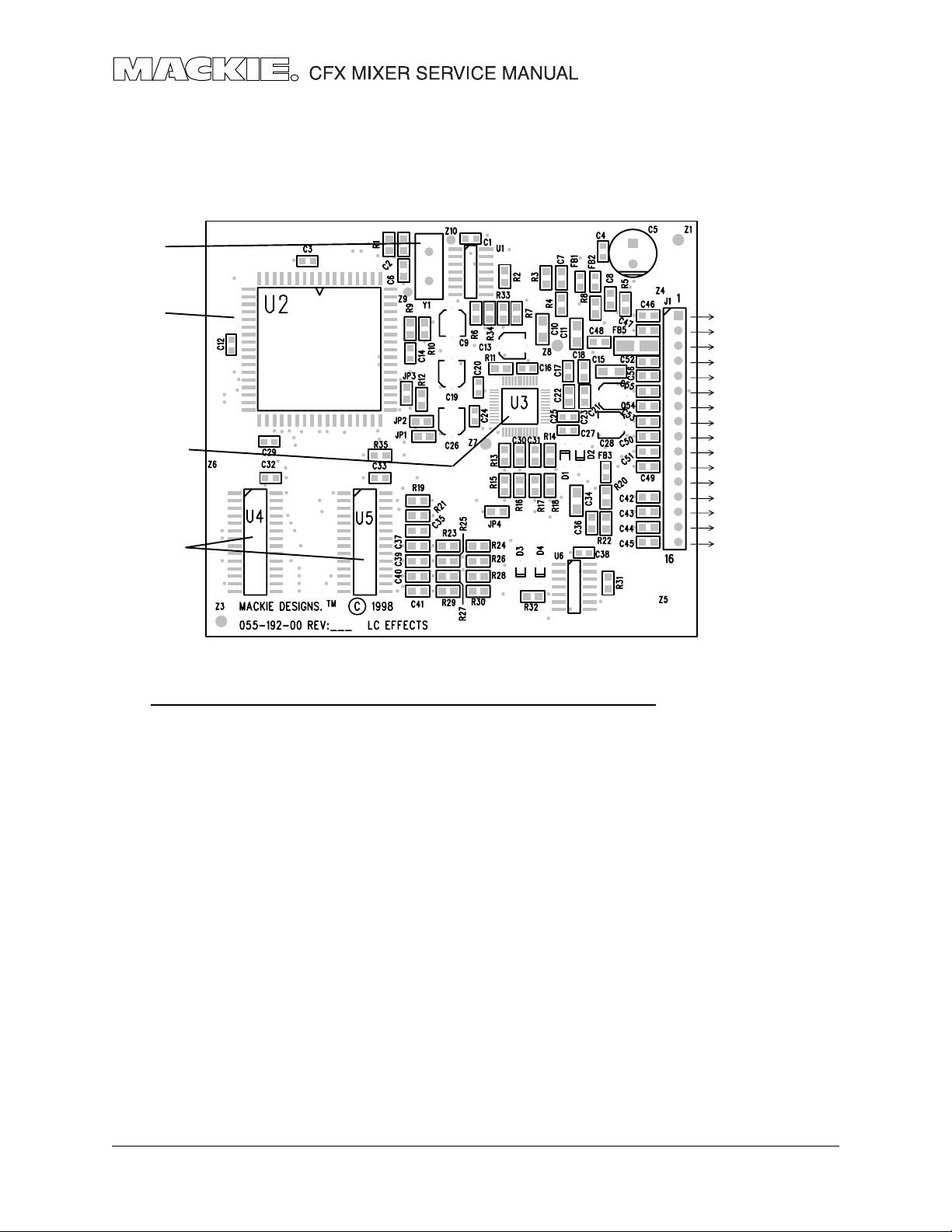
The EFX board
The EFX circuit board schematics and pcb layouts are shown in chapter 192.
The circuit is made from the following main elements: Clock, CODEC, DSP and SRAM
CLOCK Y1
DSP IC U2
CODEC IC U3
SRAM U4, U5
INTEGRATED CIRCUITS
PART NO. DESCRIPTION VALUE REF
080-088-00 IC, ADSP-2163 U2
315-017-00 CRYSTAL, 24.576 MHZ 24.576 Y1
325-027-03 IC, SMD, DUAL D F/F 74HC74A U6
325-071-03 IC, HEX, INV, SMD 74HCU04 U1
329-042-03 IC, AD1819 QFP AD1819 U3
329-047-03 IC, 32KX8 SRAM 20nS 7C256-20 U4-5
FLAG IN
BANK
+5V
DGND
MONO IN
AGND
RIGHT OUT
LEFT OUT
POT1
POT2
CLIP_LED
N/C
BIT 0
BIT 1
BIT 2
BIT 3
Bypass switch
WIDE switch
Analog input
Analog outputs
Rotary
Encoder
EFX OVERVIEW
The CODEC receives a mono analog input from the mixer circuit board and converts it
into a digital signal. The CODEC also receives analog control signals from the two
Parameter pots, converts this to digital and sends a combined digital signal to the DSP.
The DSP and the two SRAM ICs, form a powerful DSP system. The DSP receives the digital
data from the CODEC as well as the direct control signals from the rotary encoder and
the EFX WIDE switch. The DSP programing selects and performs the appropriate DSP
function on the data, and sends it back to the CODEC.
The CODEC converts the incoming digital signals to two analog outputs which are sent
to the main left and right mix, and summed to the monitor mix. For Phaser and Delay
effects, the two analog outputs from the CODEC are mono. For other effects, there is a
difference between the signals.
8
Page 9
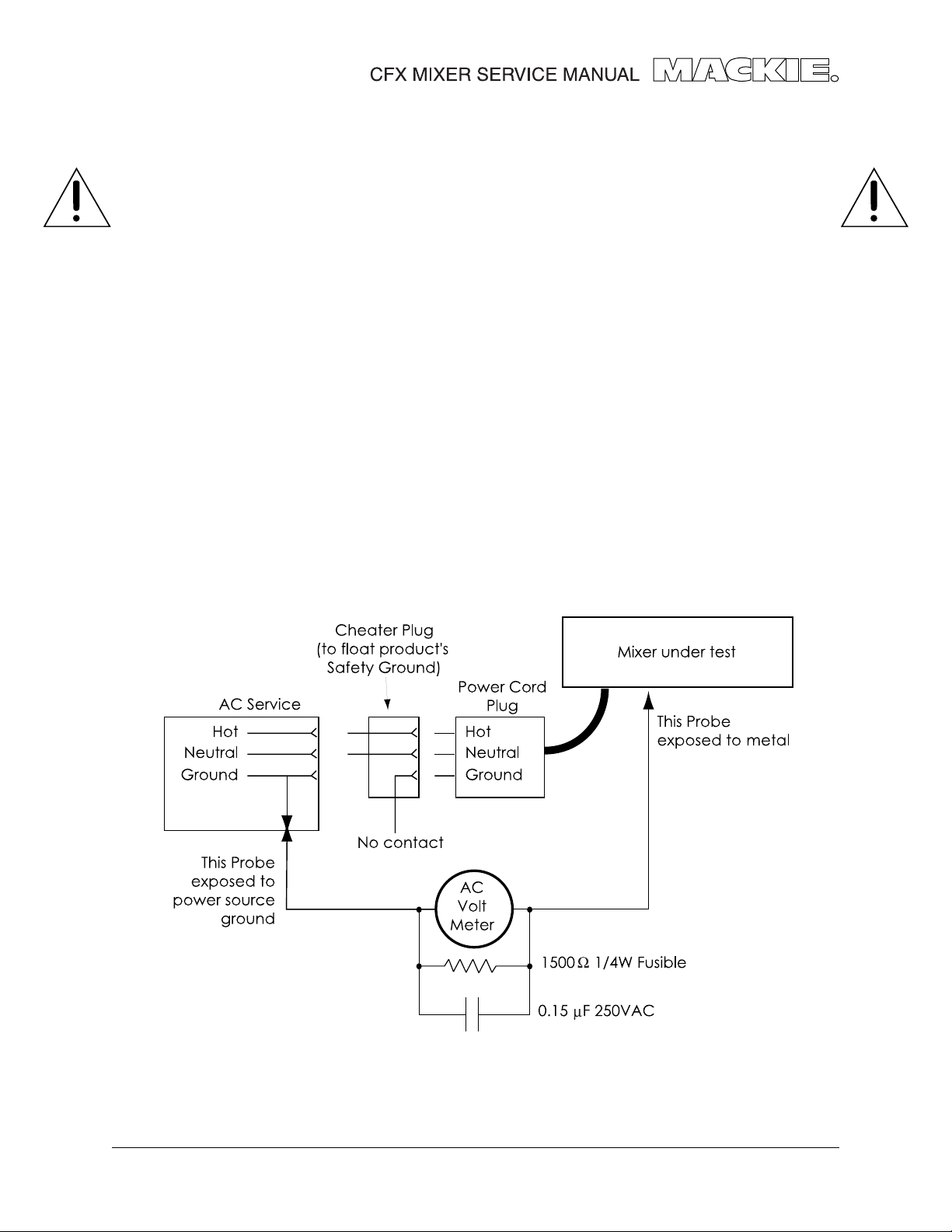
Safety test
You must perform the following leakage test before returning the mixer to your customer.
Take every safety precaution to protect yourself while doing this test.
1. Make a small loading RC circuit as shown in the diagram below, and connect
the AC volt meter between the AC power source ground and any exposed metal
on the unit under test.
2. Connect the mixer under test to an AC power source using a ground-lift adaptor,
leaving the mixer’s safety ground floating. Turn the mixer on.
3. The meter reading should be less than 750mVAC (note: this is equivalent to 0.5mA
of leakage current).
4. Flip the plug over in the receptical so the hot and neutral are swapped.
Verify that the reading is still less then 750mVAC.
5. If either reading is greater than 750mVAC, then you must investigate and repair
the mixer before returning it to your customer.
9
Page 10

Connectors
MIXER TO EFX BOARD
The details for the mixer
to EFX board
connector are shown
on page 8, but here it is
again.
MASTER CIRCUIT BOARD
J4
1
2
3 AUX_1+
4 AUX_15 AUX_2+
6 AUX_27 EFX_1+
8 EFX_1-
9 EFX_2+
10 EFX_211 +16V
12 -16V
13
14 +48V
J1
J1-1
J1-2
J1-3
J1-4
J1-5
J1-6
J1-7
J1-8
J1-9
J1-10
J1-11
J1-12
J1-13
J1-14
J1-15
J1-16
This shows the signals present on
the EFX board connector J1.
FLAG IN
BANK
+5V
DGND
MONO IN
AGND
RIGHT OUT
LEFT OUT
POT1
POT2
CLIP_LED
N/C
BIT 0
BIT 1
BIT 2
BIT 3
J44
7 -16V, BLUE
6 SIG GND, BLACK
5 +16V, RED
4 +48V , YELLOW
3 LED GND, ORANGE
2 +5V, VIOLET
1 BROWN
Bypass switch
WIDE switch
Analog input
Analog outputs
Rotary
Encoder
10
J5
1 SUB_4+
2 SUB_43 SUB_2+
4 SUB_45 SUB_3+
6 SUB_37 SUB_1+
8 SUB_1-
9 CHAN_GND
10
11
12
13 SOLO-GND
14 SOLO-CTL
PFL+
CHAN_GND
Page 11

SLAVE CIRCUIT BOARD CONNECTIONS
J4
J5
1
2
3 AUX_1+
4 AUX_15 AUX_2+
6 AUX_27 EFX_1+
8 EFX_1-
9 EFX_2+
10 EFX_211 +16V
12 -16V
13
14 +48V
1 SUB_4+
2 SUB_43 SUB_2+
4 SUB_45 SUB_3+
6 SUB_37 SUB_1+
8 SUB_1-
9 CHAN_GND
10
11
12
13 SOLO-GND
14 SOLO-CTL
PFL+
CHAN_GND
J15
J16
1
2
3 AUX_1+
4 AUX_15 AUX_2+
6 AUX_27 EFX_1+
8 EFX_1-
9 EFX_2+
10 EFX_211 +16V
12 -16V
13
14 +48V
1 SUB_4+
2 SUB_43 SUB_2+
4 SUB_45 SUB_3+
6 SUB_37 SUB_1+
8 SUB_1-
9 CHAN_GND
10
11
12
13 SOLO-GND
14 SOLO-CTL
PFL+
CHAN_GND
This shows the signals between
SLAVE boards.
This shows the signals into the
SLAVE board from the MASTER.
Actually, this is all rather sad,
that past generations fought in
the American Civil War to put a
stop to this sort of thing.
All circuit boards are created
equal.
11
Page 12

Quick Parts
BAL/UNBAL
M
6
-15dB +30dB
TRIM
LOW CUT
100 Hz
OO
OO
PRE FADER
OO
OO
-15
-15
-15
ASSIGN
dB
10
5
U
5
10
20
30
40
50
60
OO
MIC
U
G
A
C
I
+50
U
+15
U
+15
U
+15
U
+15
U
+15
U
+15
600
U
+15
LR
1
1
XLR = 400-223-00
LINE IN
1/4" jack = 400-214-00
INSERT
1
I
N
Pot = 130-030-02, Knob = 760-048-01 (white)
LED =304-028-02 (yellow)
ZERO
LEVEL
Switch = 500-037-00, Button = 760-107-00
AUX
1
2
Pot = 130-003-02
EFX
(EXT)
EFX
(INT)
EQ
1
2
HI
12k
Knob = 760-048-02 (Magenta)
Switch = 500-037-00, Button = 760-107-00
Pot = 130-002-02
Knob = 760-048-03 (Blue)
MID
FREQ
1.5k150
Pot = 130-064-02, Knob = 760-048-04 (Dk Grey)
8k100
LOW
80Hz
Pot = 130-002-02, Knob = 760-048-03 (Blue)
PAN
Pot = 130-003-02, Knob = 760-048-04 (Dk Grey)
Switch = 500-037-00, Button = 760-108-00
MUTE
-
2
1
3-4
Switch = 500-037-00, Button = 760-107-00
SOLO
PFL
12
Fader = 130-031-00, Knob = 760-037-01
Page 13

All 1/4" jacks = 400-214-00
Quad RCA jack = 400-022-00
XLR = 400-041-00
Switch = 500-037-00
Button = 760-108-00
Switch = 500-037-00
Button = 760-107-00
STEREO EFX
RETURN
LR
1
EFX SEND
2
(MONO) (MONO)
11
LEFT
RIGHT
12
11
U
12
+20-20
TRIM
AUX
U
1
+15
OO
U
2
+15
OO
PRE FADER
U
EFX
1
(EXT)
+15
OO
U
EFX
2
(INT)
+15
OO
EQ
U
HI
12k
-15
+15
U
HI
MID
3k
-15
+15
U
MID
400Hz
-15
+15
U
LOW
80Hz
-15
+15
PAN
LR
11-12
ASSIGN ASSIGN
MUTE
dB
10
5
U
5
10
20
30
40
50
60
OO
1
3-4
SOLO
PFL
dB
10
-
2
5
U
5
10
20
30
40
50
60
TRIM
OO
OO
PRE FADER
OO
OO
-15
-15
-15
-15
LR
9-10
ASSIGN
dB
10
5
U
5
10
20
30
40
50
60
OO
U
U
U
U
U
U
U
U
U
9
LEFT
RIGHT
10
9
10
+20-20
AUX
1
+15
2
+15
EFX
1
(EXT)
+15
EFX
2
(INT)
+15
EQ
HI
12k
+15
HI
MID
3k
+15
LOW LOW
MID
400Hz
+15
LOW
80Hz
+15
PAN
MUTE
1
-
2
3-4
SOLO
PFL
TAPE
OUTPUT
MAIN INSERT
L
TAPE
INPUT
1
L
MAIN OUT
LL
R
R
2
R
1
1
L
2
2
R
AUX SENDUTILITY OUT
SUB OUT
MAIN OUT
LAMP
12V 0.5A
L
R
EFX
3
R
FOOT
SWITCH
4
S
75Hz
SUB OUT
PHONES
Pot = 130-061-02, Knob = 760-048-01 (white)
Pot = 130-003-02
Knob = 760-048-02 (magenta)
Switch = 500-037-00, Button = 760-107-00
Pot = 130-061-02, Knob = 760-048-03 (blue)
Pot = 130-061-02, Knob = 760-048-04 (dark grey)
Pot = 130-061-02, Knob = 760-048-03 (blue)
Pot = 130-003-02, Knob = 760-048-04 (dark grey)
SUB
OO
1
LEFT
RIGHT
SUB
ASSIGN
dB
10
5
U
5
10
20
30
40
50
60
OO
2
LEFT
RIGHT
SUB
ASSIGN
dB
10
5
U
5
10
20
30
40
50
60
OO
3
LEFT
RIGHT
SUB
ASSIGN
dB
10
5
U
5
10
20
30
40
50
60
OO
4
LEFT
RIGHT
STEREO
MAIN MIX
dB
10
5
U
5
10
20
30
40
50
60
OO
Fader = 130-032-00 (dual)
Knob = 760-037-01
Fader = 130-031-00 (mono)
Knob = 760-037-03 (blue)
Fader = 130-032-00 (dual)
Knob = 760-037-01
13
Page 14

Pot = 130-003-02
Knob= 760-048-02
(magenta)
Red LED = 304-027-02
Pot = 130-061-02
Knob= 760-048-01 (white)
Pot = 130-003-02
Knob= 760-048-01 (white)
Encoder = 500-045-00
Knob= 760-091-00
Pot = 130-022-02
Knob= 760-048-03 (blue)
MASTER SEND
U
+15
OO
U
+15
OO
U
+15
OO
CLIP
U
+15
OO
EFX 2
SEND
REVERSE
GATED
CATHEDRAL
LG. HALL
MD.HALL
LG. PLATE
MD.PLATE
SM. ROOM
NORMAL NORMAL
100
TIME
RATE
15
10
AUX
5
0
1
5
10
15
2
EFX
1
(EXT)
EFX 2 (INT) RETURN MASTERS
U
+15
OO
TO MAIN MIX
WIDE BYPASS
REVERBS
CHORUS/FLANGE/PHASER
CFX12 MIXER
12 CHANNEL COMPACT INTEGRATED LIVE SOUND MIXER
U
+15
OO
1 AUX 2
AUX
EFFECTS TO MONITOR
DELAY 1
DELAY 2
DELAY 3
DELAY 4
CHORUS
FLANGE
PHASER
SPRING
EFX
DELAYS
1K50025063 125 16K2K 4K 8K
STEREO GRAPHIC EQ
U
+15
OO
(MUTES ALL CHANNELS)
100
DAMPING
DEPTH
U
+20
OO
EFX 1 RETURN
U
+20
OO
TAPE LEVEL
BREAK SWITCH
OO
MAX
PHONES LEVEL
U
+10
OO
UTILITY OUT LEVEL
PHANTOM POWER
POWER STATUS
ZERO
LEVEL
SET
RUDE SOLO
48v
LEFT RIGHT
22
10
7
4
2
0
2
4
7
10
20
30
=
0dBu
0dB
15
10
5
0
All Faders = 130-075-00
5
10
15
Yellow LED = 304-028-02
Switch = 500-037-00
Button = 760-107-00
Red LED = 304-027-02
CLIP
Red LED = 304-027-02
Yellow LED = 304-028-02
Green LED = 304-029-02
RED LED = 304-002-00
Feet = 750-001-00
Switch = 500-037-00
Button = 760-107-00
Red LED = 304-027-02
POWER
ON
IEC Power socket = 400-132-00
Pot = 130-061-02
Knob= 760-048-01 (white)
Switch = 500-037-00
Button = 760-107-00
14
Power Switch = 500-052-00
Page 15

PARTS LIST
Click any item to open that page
Parts Numbering guide
040- Cables
055- Finished PCB Assy
100- Pots and resistors
200- Capacitors
300- Semiconductors
400- Jacks/Connectors
500- Switches
510- Fuses
550- Chassis Metalwork
600- Transformers
601- Inductors
610- Wires and Cables
640- AC line cords
700- Hardware
760- Knobs/Plastic
PART# DESCRIPTION PAGES
090-063-00 MASTER PARTS A-2
055-192-00 EFFECTS BOARD A-4
055-241-00 MASTER BOARD A-5
055-242-00 SLAVE 4 BOARD A-10
055-258-00 POWER SUPPLY BOARD A-12
055-260-00 AC INPUT BOARD A-12
770- Fans
790- Misc./Packing
800- Printed Material
860- EPROM
Components noted with this symbol shall be replaced only by the component specified.
This is required to maintain product safety.
A-1
Page 16

Master Parts List CFX Assembly
Item# Part # Description R ev Qt y N otes
090-120-00 CFX12 A3-A2 1 CFX12 ASSEMBLY
090-121-00 CFX16 A3-A2 1 CFX16 ASSEMBLY
090-122-00 CFX20 A3-A2 1 CFX20 ASSEMBLY
1 040-358-00 CBL RIB 18G 7P .156 16IN B 1
4 055-192-00-01 PCB ASSY LC EFTS-PWR MIX B1-A1 1 See Page A-4
055-241-00-02 ASSY PCB CFX MASTER A-A2 1 See Page A-5
6 055-242-00-01 ASSY PCB CFX SLAVE 4 1-A1 1 See Page A-10
7 055-258-00-01 PCB ASSY PWR SPLY CFX A-A1 1 See Page A-12
8 055-260-00-01 PCB ASSY AC INPUT CFX A-A1 1 See Page A-12
9 080-142-00 SA XFMR -010 120V A-A1 1 120V models (all CFX)
9 080-142-01 SA XFMR -010 230V A 1 230V models (all CFX)
9 080-142-02 SA XFMR -010 100V A 1 100V models (all CFX)
2 080-144-00 SA BNC CFX 12/16/20 C1 A 1 1
44 400-365-00 QDISK TAB .250 M #6 MNT A 1
11 410-005-00 INSL SILPAD TO-220 A 4
12 510-001-00 FUSE SB 1A 5X20MM 250V UL B 1 120V models (all CFX)
12 510-002-00 FUSE SB .5A 5X20 250V IEC C 1 230V models (all CFX)
12 510-025-00 FUSE SB 1.25A 5X20MM 250V B 1 100V models (all CFX)
13 550-442-00 CHASSIS TOP CXF 12 1 CFX12
13 550-443-00 CHASSIS TOP CXF 16 A 1 CFX16
13 550-444-00 CHASSIS TOP CXF 20 A 1 CFX20
14 550-445-00 CHASSIS BOTTOM CXF 12 A 1 CFX12
14 550-446-00 CHASSIS BOTTOM CXF 16 A 1 CFX16
14 550-447-00 CHASSIS BOTTOM CXF 20 A 1 CFX20
15 550-462-00 CLAMP TO-220 X 4 A 1
43 550-491-00 FAB PLT HTSK CFX PWR SPLY A 1
16 550-551-10 PNT LEFT SIDE CFX A 1
17 550-551-20 PNT RIGHT SIDE CFX A 1
18 550-552-00 BACK CFX 12 B 1 CFX12
18 550-553-00 BACK CFX-16 B 1 CFX16
18 550-554-00 BACK CFX-20 B 1 CFX20
20 620-045-00 CBL FLT 14C W/PINS 3.5IN A 2, 4, 6 (2 for CFX•12, 4=•16, 6=•20)
640-001-00 LC IEC SJT 10A/125V 6FT D 1 120v Linecord
640-002-02 LC JAPAN 12A 125VAC 8FT C 1 100V Linecord
22 700-010-00 TF 6-32X1/4 PHP BLKZC A 26
23 700-011-00 MCH 4-40X1/4 BTNSKT BLKOX A 34, 44, 54
24 700-028-01 SEMS 6-32X5/16 PHP BLKZC B 6
25 700-028-03 SEMS 6-32X1/2 PHP BLKZC B 4
26 701-016-00 5-20X5/16 PHPII TYP B BLK A 23, 31, 39
27 705-001-00 KEPNUT 6-32 A 4
28 705-003-00 NUT HEX-SPLD W/400-214-00 A AR
29 705-008-00 NUT LOCK 8-32 A 2
31 710-002-00 WASHER-SPLD W/400-214-00 A AR
33 750-001-00 BUMPON ROUND BLK .63X.31 A 4
34 760-037-01 KNOB SLIDE 10X25MM MLDLIN A 11, 15, 19
35 760-037-03 KNOB SLIDE 11X24 BLUE A 4
36 760-048-01 KNOB 9MM LT GRY B 17, 21, 25
760-048-02 KNOB 9MM MAGENTA B 44, 60, 76
760-048-03 KNOB 9MM BLU/GRY B 34, 46, 58
39 760-048-04 KNOB 9MM DARK GRAY B 18, 26, 34
40 760-091-00 KNOB MASTER VOLUME A 1
41 780-050-00 LIPSEAL MASTER CFX A 1
42 780-051-00 LIPSEAL SLAVE 4 CFX A 1, 2, 3
Note: The Item numbers in the first column refer to the circled numbers in the exploded views,
chapters B, C and D.
A-2
Components noted with this symbol shall be replaced only by the component specified.
This is required to maintain product safety.
Page 17

Item# Part # Description R ev Qt y N otes
790-002-00 BAG POLY 12 X 18 2MIL A 1
790-027-00 BAG POLY 20X7X36 4MIL GUS A 1
800-130-00 BOX CMPT CFX 12 B 1 CFX12
800-131-00 BOX CMPT CFX 16 B 1 CFX16
800-132-00 BOX CMPT CFX 20 B 1 CFX20
810-086-00 FOAM SET CFX 1
820-104-00 OWNR MNL COMPACT CFX A 1 COVERS ALL CFX
A-3
Page 18

055-192-00 REV B, Effects board
PART NO. DESCRIPTION VALUE REFERENCE DESIGNATORS
080-088-00 IC, ADSP-2163 U2
140-009-00 RESISTOR TF SMT 2.2 5% R11
140-049-00 RES TF SM .1W 5% 100 OHM 100 5% R33-34
140-053-00 RESISTOR TF SMT 15 0 5% R13-14
140-073-00 RESISTOR TF SMT 1K0 5% R4 R8-9 R20 R31
140-089-00 RESISTOR TF SMT 4K7 5% R19 R21 R23-30
140-097-00 RESISTOR TF SMT 10K 5% R7 R10 R32
140-097-00 RESISTOR TF SMT *DO NOT STUFF* 1 0K 5% R16-18 R15
140-114-00 RESISTOR TF SMT 47K 5% R3 R5-6 R22
140-123-00 RESISTOR TF SMT 100K 5% R2 R12
140-123-00 RES TF SM .1W 5% 100K OHM 100K 5% R35
140-139-00 RESISTOR TF SMT 470K 5% R1
212-001-00 CAPACITOR CERAMIC SMT 0.01 10% C30-31
212-003-00 CER 100PF 5% 50V NPO SM 100PF 5% C46 C49
212-005-00 CAPACITOR CERAMIC SMT 20PF 5% C2 C6
212-007-00 CAPACITOR CERAMIC SMT 0.047 5% C18
212-016-00 CER 1000PF 5% 5OV NPO SM 1000PF 5% C42-45 C47-48 C50-56
212-023-00 CAPACITOR CERAMIC SMT 0.001 10% C7-8 C36
212-024-00 CER 1UF 25V Y5V 1206 1UF -400 C10-11 C15 C34
212-027-00 CAPACITOR CERAMIC SMT .1UF 10% C1 C3-4 C12 C14 C16-17 C20 C24-25 C27
C29 C32-33 C38
212-029-00 CAPACITOR CERAMIC SMT 270PF 5% C22-23
212-032-00 CAPACITOR CERAMIC X7R SMT 2200PF 10% C35 C37 C39-41
220-011-00 LYT 100UF 20% 25V RAD 100U F 10 % C5
223-003-00 LYT 22UF 20% 6.3V SM 22UF 20% C9
223-004-00 LYT 10UF 20% 16V SM 10UF 20% C13 C19 C21 C26 C28
300-003-00 DIODE SIGNAL SMD DL4148 D1-4
315-017-00 CRYSTAL, 24.576 MHZ 24.576 Y1
325-027-03 IC, SMD, DUAL D F/F 74HC74A U6
325-071-03 IC, HEX, INV, SMD 74HCU04 U1
329-042-03 IC, AD1819 QFP AD1819 U3
329-047-03 IC, 32KX8 SRAM 20nS 7C256-20 U4-5
400-280-00 HDR, SKT, 16P, .1X1 STR 1.75 J1
450-192-00 PCB, LC EFFECTS Z1
601-009-00 FERRITE BEAD, SMT Z=1000 FB1-3
601-010-00 FERRITE SMT POWER Z=73 FB5
192b
A-4
Page 19

241a
055-241-00 REV A, Master board
PART NO. DESCRIPTION VALUE REFERENCE DESIGNATORS
040-137-00 CBL ASSY, 18GA 1010 GRN/YEL 9” E2
LUG/AMP IN
130-002-02 POT RTY 50KB 9MM MNO H TN 50KB R47 R55 R59 R126 R135 R139 R209 R220
R224 R285 R294 R298
130-003-02 POTRTY 50KG 9MM MN TN PAN 50KG R32-33 R38-39 R63 R112-113 R118-119
R143 R195-196 R201-202 R228 R273-274
R279-280 R304 R332-333 R340-341 R387
R429-430 R438-439 R492 R525-526 R531
R535 R617 R621
130-022-02 RESISTOR POT 9MM HORIZ 10KB R545 R629
130-030-02 RESISTOR POT 9MM HORIZ 5KZY R15 R95 R180 R260
130-031-00 POT SLD 10KD 60MM MONO 10KD R74 R154 R239 R316 R562 R569 R648 R713
130-032-00 POT SLD 50KD 60MM DUAL 50KD R398 R503 R861
130-061-02 POT 50KG 12MM DUAL WO SLV 50KG R320 R350 R360-361 R374 R417 R450
R464-465 R481 R539 R744 R748 R753 R759
130-064-02 POT 500KC 12MM DUL WO SLV 500KC R56 R136 R221 R295
130-075-00 POT SLD 50KW 30MM PANA 50KW R603 R605 R664-665 R669 R729 R732 R735
R825
140-032-00 RESISTOR CF 20 5% R848
140-037-00 RESISTOR CF 33 5% R847
140-049-00 RESISTOR TF SMT 10 0 5% R624
140-051-00 RES TF SM .1W 5% 120 OHM 120 5% R407 R409 R412 R415 R514 R516 R576
R578 R652 R654 R786 R790 R846
140-057-00 RESISTOR CF 220 5% R852-853 R857-860
140-061-00 RESISTOR CF 330 5% R842 R844
140-064-00 RES TF SM .1W 5% 430 OHM 430 5% R765
140-065-00 RESISTOR CF 47 0 5% R841 R843 R845
140-066-00 RES TF SM .1W 5% 510 OHM 510 5% R35 R37 R40-41 R70-73 R115 R117 R121
R132 R150-153 R198 R200 R204 R215
R235-238 R276 R278 R282 R291 R312-315
R336-337 R347 R356 R394-397 R433-434
R445 R456 R499-502 R618 R675 R840
R850-851
140-068-00 RESISTOR CF 620 5% R839
140-073-00 RES TF SM .1W 5% 1K0 OHM 1K0 5% R10 R13 R53-54 R60 R62 R85 R88 R133-134
R140 R142 R170 R173 R216-217 R225 R227
R255 R258 R292-293 R299 R301 R351-354
R365-368 R370-372 R376 R378-381
R451-454 R461-462 R469-472 R474-476
R479-480 R483-487 R494 R534 R552 R623
140-074-00 RESISTOR CF 1K1 5% R574-575
140-076-00 RESISTOR CF 1K3 5% R838
140-077-00 RESISTOR TF SMT 1K5 5% R548 R628
140-079-00 RES TF SM .1W 5% 1K8 OHM 1K 8 5% R568 R572 R647 R650
140-080-00 RES TF SM .1W 5% 2K0 OHM 2K 5% R23 R103 R187 R265 R622 R747 R834 R837
140-083-00 RESISTOR TF SMT 2K7 5% R547 R627
140-084-00 RESISTOR TF SMT 3K0 5% R5-6 R9 R12 R80-81 R84 R87 R165-166
R169 R172 R250-251 R254 R257
140-085-00 RES TF SM .1W 5% 3K3 OHM 3K 3 5% R691-692
140-086-00 RES TF SM .1W 5% 3K6 OHM 3K 6 5% R327 R329 R421 R423
140-087-00 RESISTOR CF 3K9 5% R51 R61 R131 R141 R214 R226 R290 R300
R303 R382-384 R386 R488 R490-491 R836
140-088-00 RES TF SM .1W 5% 4.3K 4 K 3 5% R556-557 R636-637 R701-702 R766-767
A-5
Page 20

PART NO. DESCRIPTION VALUE REFERENCE DESIGNATORS
140-089-00 RES TF SM .1W 5% 4K7 OHM 4K 7 5% R29 R64-69 R109 R144-149 R182-183
R229-234 R305-311 R388-393 R493
R495-498
140-090-00 RES TF SM .1W 5% 5K1 OHM 5K 1 5% R20 R34 R36 R42-43 R57-58 R100 R114
R116 R120 R122 R137-138 R156 R158 R184
R194 R197 R199 R203 R205 R222-223 R241
R245 R275 R277 R281 R283 R296-297
R334-335 R338-339 R342-346 R348-349
R355 R400 R404 R431-432 R435-436
R440-444 R446-447 R455 R505 R509 R522
R529 R533 R538 R553-554 R563 R642 R707
R770 R776-777
140-091-00 RESISTOR CF 5K6 5% R835
140-094-00 RES TF SM .1W 5% 7K5 OHM 7K 5 5% R50 R130 R213 R289 R358-359 R459-460
R558 R638 R693 R698 R703 R768 R854
R868
140-097-00 RES TF SM .1W 5% 10K OHM 10 K 5% R44-45 R75 R123-124 R160 R206-207
R218-219 R244 R317 R448 R458 R540-541
R543-544 R549 R555 R559-561 R567 R580
R583-584 R586-588 R590-591 R597-599
R601 R609 R612-613 R615-616 R619-620
R625-626 R633-635 R639-641 R646
R657-658 R672-673 R676-677 R686-687
R694-696 R699-700 R704-706 R709 R711
R714 R718-719 R722 R739-740 R743 R754
R764 R769 R771-773 R782 R784 R789
R793-795 R797 R799 R812 R814 R817-823
R826 R828 R833 R849 R869 R872 R875
R877
140-098-00 RES TF SM .1W 5% 11K OHM 11 K 5% R155 R157 R240 R243 R399 R403 R504
R508 R565 R570 R644 R649
140-101-00 RES TF SM .1W 5% 15K OHM 15 K 5% R159 R161 R242 R246 R377 R463 R478
R489 R571 R573 R651 R716
140-104-00 RES TF SM .1W 5% 20K OHM 20K 5% R30 R46 R91 R110 R125 R176 R208 R284
R542 R546 R874 R876
140-105-00 RESISTOR TF SMT 22K 5% R537
140-108-00 RESISTOR TF SMT 27K 5% R11 R86 R171 R256
140-109-00 RES TF SM .1W 5% 30K OHM 30 K 5% R262 R272 R323 R325 R328 R331 R405-406
R419 R422 R425 R427 R437 R449 R510-511
R518 R521 R527 R536 R680-681 R688-690
R697 R749-750 R755-756 R760-761
140-111-00 RES TF SM .1W 5% 36K OHM 36 K 5% R25 R105 R189 R267 R678-679 R682-683
140-112-00 RES TF SM .1W 5% 39K OHM 39 K 5% R870-871
140-114-00 RES TF SM .1W 5% 47K OHM 47 K 5% R48-49 R127-128 R210-211 R286-287 R302
R357 R364 R375 R385 R457 R468 R482
140-119-00 RES TF SM .1W 5% 75K 75K 5% R362-363 R369 R373 R466-467 R473 R477
140-123-00 RES TF SM .1W 5% 100K OHM 100K 5% R3-4 R17 R27 R31 R52 R78-79 R89 R94 R97
R107 R111 R129 R164 R174 R179 R191
R193 R212 R249 R269 R271 R288 R318-319
R321-322 R324 R326 R330 R411 R414 R418
R420 R424 R512-513 R519-520 R528 R532
R550-551 R564 R566 R630-632 R643 R645
R708 R710 R751-752 R757-758 R762 R774
R778 R785 R787 R791 R810-811 R855-856
R862-863
140-130-00 RES TF SM .1W 5% 200K OHM 200K 5% R401-402 R506-507 R796 R798
241a
A-6
Page 21

241a
PART NO. DESCRIPTION VALUE REFERENCE DESIGNATORS
141-051-00 RES TF SM .25W 5% 120 OHM 12 0 5% R28 R108 R192 R270 R408 R410 R413 R416
R515 R517 R577 R579 R653 R655 R763
R775 R779-781 R783 R788 R792 R800-809
R865-866
145-066-00 RES MF SM .1W 1% 4.75 OHM 4.75 1% R16 R96 R181 R261
145-279-00 RES MF SM .1W 787 OHM 787 1% R596 R608
145-288-00 RESISTOR MF SMT 976 1% R723 R730
145-296-00 RESISTOR MF SMT 1K18 1% R816 R831
145-307-00 RESISTOR MF SMT 1K54 1% R593 R604
145-317-00 RESISTOR MF SMT 1K96 1% R663 R670
145-330-00 RES MF SM .1W 1% 2K43 OHM 2K43 1% R684-685 R745-746
145-330-00 RESISTOR MF SMT 2K43 1% R727 R736
145-339-00 RESISTOR MF SMT 3K01 1% R14 R90 R175 R259 R592 R602
145-341-00 RES MF SM .1W 1% 3K16 OHM 3K16 1% R426
145-346-00 RES MF SM .1W 1% 3K57 OHM 3K57 1% R19 R93 R99 R178
145-350-00 RESISTOR MF SMT 3K92 1% R660 R666
145-352-00 RES MF SM .1W 1% 4K12 OHM 4K12 1% R18 R92 R98 R177
145-356-00 RES MF SM .1W 1% 4K53 OHM 4K53 1% R712 R715
145-358-00 RESISTOR MF SMT 4K75 1% R726 R734
145-368-00 RESISTOR MF SMT 6K04 1% R595 R607
145-373-00 RES MF SM .1W 1% 6K81 OHM 6K81 1% R428
145-377-00 RESISTOR TF SMT 7K50 1% R724 R731
145-388-00 RESISTOR MF SMT 9K76 1% R815 R832 R864 R867 R873
145-389-00 RES MF SM .1W 1% 10K0 OHM 10K0 1% R21-22 R24 R26 R101-102 R104 R106
R185-186 R188 R190 R263-264 R266 R268
145-397-00 RESISTOR MF SMT 12K1 1% R585 R594 R606 R614
145-406-00 RESISTOR MF SMT 15K0 1% R662 R668 R717 R738
145-416-00 RESISTOR MF SMT 19K1 1% R728 R737
145-417-00 RESISTOR MF SMT 19K6 1% R813 R830
145-418-00 RES MF SM .1W 1% 20K0 OHM 20K0 1% R7-8 R82-83 R167-168 R252-253
145-426-00 RESISTOR MF SMT 24K3 1% R582 R589 R600 R611
145-435-00 RESISTOR MF SMT 30K1 1% R659 R661 R667 R674
145-445-00 RESISTOR MF SMT 38K3 1% R721 R725 R733 R742
145-455-00 RESISTOR MF SMT 48K7 1% R581 R610
145-456-00 RES MF SM .1W 1% 49K9 OHM 49K9 1% R523-524 R530 R824 R827 R829
145-464-00 RESISTOR MF SMT 60K4 1% R656 R671
145-474-00 RESISTOR MF SMT 76K8 1% R720 R741
146-373-00 RES MF SM .25W 1% 6K81 OHM 6K81 1% R1-2 R76-77 R162-163 R247-248
200-010-02 PLY .0018UF 10% 100V TR 0.0018 2.00% C34 C75 C121 C163 C192-193 C234-235
200-011-02 CAPACITOR MYLAR T&R 0.0022 2.50% C409-412 C420-423 C467-468 C480-481
200-013-02 PLY .0082UF 10% 100V TR 0.0082 2.00% C195-198 C236-237 C241-242
200-014-02 PLY .0033UF 10% 100V TR 0.0033 2.50% C35-36 C76-77 C123-124 C164-165
200-025-02 PLY/BX .56UF 5% 63V TR 0.56 C39 C80 C127 C168 C171 C203 C210
C249
200-029-02 CAPACITOR MYLAR T&R 0.22 10% C316-319 C330-333 C354-355 C367-368
C500-501 C505
200-031-02 PLY .022UF 2% 50V TR 0.022 5% C199-200 C204-205 C243-244 C250-251
C356-359 C369-372 C407-408 C418-419
212-001-00 CER .01UF 10% 50V X7R SM 0.01 10% C14 C17-18 C20 C24 C29 C31 C54 C57
C59 C61 C65 C70 C72 C82 C85 C99
C102-103 C105-106 C110 C115-116 C118
C122 C130-131 C147 C150 C154 C160
C230 C238 C265 C272-273 C277-280
C291-292 C320 C322-325 C328-329
C360-366 C373 C376 C413-417 C471-474
C478-479 C482-483 C488 C509-510
C516-517
A-7
Page 22

PART NO. DESCRIPTION VALUE REFERENCE DESIGNATORS
212-003-00 CER 100PF 5% 50V NPO SM 100PF 5% C334 C338
212-004-00 CER 220PF 5% 50V NPO SM 220PF 5% C5 C45 C90 C138
212-005-00 CER 20PF 5% 50V NPO SM 20PF 5% C81 C83 C129 C132 C180 C184 C188
C212 C215 C224 C255 C258 C264 C266
C275 C282 C290 C303 C309 C313 C340
C342 C348 C351 C374-375 C378-380
C384-385 C391-393 C399 C402 C440
212-006-00 CAPACITOR CERAMIC SMT 470PF 5% C2 C4 C6 C11 C42 C44 C46 C51 C87 C89
C91 C96 C135 C137 C139 C144
212-007-00 CER .047UF 20% 50V Z5U SM 0.047 20% C513
212-009-00 CER 47PF 5% 50V NPO SM 47PF 5% C12-13 C52-53 C97-98 C145-146
C228-229 C231-232 C308 C347 C398
C441 C444-445 C450 C454 C457 C460
C504 C506
212-010-00 CAPACITOR CERAMIC SMT .1UF -400 C19 C58 C60 C104 C170 C182-183 C202
C207 C214 C217 C222-223 C239-240
C245-246 C248 C257 C260 C285 C287
C295 C297 C300-302 C304-305 C310
C314 C336-337 C339 C343-344 C349
C352 C377 C381-383 C386-389 C394-395
C400 C403 C442-443 C447-448 C452
C455 C458 C461 C463-464 C485
C489-493 C496-497 C507-508 C514-515
212-015-00 CAPACITOR CERAMIC SMT 33PF 5% C288 C293
212-018-00 CER 10PF 5% 50V NPO SM 10PF 5% C32 C73 C119 C161 C169 C201 C206
C247
212-019-00 CAPACITOR CERAMIC SMT 150PF 5% C10 C15 C21 C23 C50 C55 C62 C64 C95
C100 C107 C109 C143 C148 C151 C153
212-021-00 CAPACITOR CERAMIC SMT 27pF C270-271 C276 C321 C326-327 C469-470
C475-477 C484
212-023-00 CAPACITOR CERAMIC SMT 0.001 10% C9 C49 C94 C142 C175 C220
220-002-02 LYT 47UF 20% 25V RAD TR 47UF 20% C3 C8 C26 C28 C30 C33 C37-38 C40 C43
C48 C67 C69 C71 C74 C78-79 C84 C88
C93 C112 C114 C117 C120 C125-126
C128 C133 C136 C141 C156 C158-159
C162 C166-167 C172-174 C176-179 C181
C185-187 C189-191 C194 C208-209 C211
C213 C216 C218-219 C221 C225-227
C233 C252-254 C256 C259 C261-263
C267-269 C274 C281 C283-284 C286
C289 C294 C296 C306-307 C311-312
C315 C335 C341 C345-346 C350 C353
C390 C396-397 C401 C404-406 C424-439
C446 C449 C451 C453 C456 C459 C462
C465-466 C486-487 C494-495 C498-499
C502-503 C511-512
220-003-02 LYT 47UF 20% 50V RAD TR 47UF 10% C1 C7 C41 C47 C86 C92 C134 C140
220-004-02 CAPACITOR LYTIC RADIAL T&R 470UF 10% C16 C56 C101 C149
220-008-02 LYT 1UF 20% 50V RAD TR 1UF 10% C298-299
220-013-02 LYT .22UF 20% 50V RAD TR .22UF 10% C22 C25 C27 C63 C66 C68 C108 C111
C113 C152 C155 C157
241a
A-8
Page 23

241a
PART NO. DESCRIPTION VALUE REFERENCE DESIGNATORS
300-003-00 DIODE SIGNAL SMD DL4148 D24-25 D54-59
301-004-00 DIO PWR DL4002 SM DL4002 D1-4 D6-9 D11-14 D16-19
302-010-03 DIO ZEN DL5232B 5.6V SM DL5232 D22-23
304-002-00 LED RED T1-3/4 W FLASHER RED D5 3
304-027-02 LED RED W/.425 SPACER TR RED D21 D26 D28 D40-41
304-028-02 LED YEL W/.425 SPACER TR YEL D5 D10 D15 D20 D27 D29 D42
304-029-02 LED GRN W/.425 SPACER TR GRN D30-39 D43-52
310-002-02 XSTR PNP 2N4403 T/A 2N4403 Q12-13
311-001-00 XSTR NPN IMBT4401 SM IMBT4401 Q9-11
311-002-00 X-SISTOR PNP SMD IMBT4403 Q1-8
320-011-00 I.C. LINEAR NJM 4560 U60-61
320-012-00 OPAMP NJM4560M NJM4560M U1 U3-5 U7-31 U33-34 U36-39 U41-59
U62-65 U72-77
323-002-00 I.C. QUAD COMPARATOR SMD LM339 U2 U6 U66-71
325-086-03 IC, ANALOG MUX/DEMUX 74HC4053 U32 U35 U40
400-022-00 CONNECTOR JACK QUAD RCA HORIZ J25
400-041-00 CONNECTOR XLR PC MTG VERT MALE J39-41
400-048-00 HDR 7P .156X1 RTA J44
400-214-00 JACK 1/4 V PCMNT 1MM WASH J2-3 J7-8 J10-11 J13-24 J26-33 J35-38
J42-43
400-223-00 CONNECTOR XLR PC MTG VERT FML J1 J6 J9 J12
400-349-00 HDR SKT BOT ENTRY 14P .100X1 J4-5
450-241-00 PCB, CFX: MAIN Z2
500-037-00 SWITCH 2PDT PUSH V SNAPIN 2P2T SW1-46
500-045-00 SW ROT ENCODER 15.5MM 4BIT S1
601-010-00 FERRITE BEAD, SMT Z=73 L1
620-042-00 CBL FLEX STRIP 16C .1X1 4IN J34
660-002-00 JUMPER WIRE 24GA T&R Z1 Z5-7 Z50 Z901
660-002-00 JUMPER WIRE 24GA T&R JP1-76
706-009-00 SPACER, NYLON, LED .385 Z8
706-033-01 STDF SWAGE NO.4 X .542L F H1-21
706-038-00 STDF NO.4 X .250L H22-24
760-107-00 BTN 2 COLOR 9X5MM B1-2 B4-8 B10-14 B16-20 B22-25 B27-30
B32-46
760-108-00 BTN 2 COLOR 9X9MM B3 B9 B15 B21 B26 B31
A-9
Page 24

550-242-00 REV A, Slave 4 board
PART NO. DESCRIPTION VALUE REFERENCE DESIGNATORS
130-002-02 POT RTY 50KB 9MM MNO H TN 50KB R47 R55 R59 R126 R135 R139 R209 R220
R224 R285 R294 R298
130-003-02 POTRTY 50KG 9MM MN TN PAN 50KG R32-33 R38-39 R63 R112-113 R118-119
R143 R195-196 R201-202 R228 R273-274
R279-280 R304
130-030-02 RESISTOR POT 9MM HORIZ 5KZY R15 R95 R180 R260
130-031-00 POT SLD 10KD 60MM MONO 10KD R74 R154 R239 R316
130-064-02 POT 500KC 12MM DUL WO SLV 500KC R56 R136 R221 R295
140-066-00 RES TF SM .1W 5% 510 OHM 510 5% R35 R37 R40-41 R70-73 R115 R117 R121
R132 R150-153 R198 R200 R204 R215
R235-238 R276 R278 R282 R291 R312-315
140-073-00 RES TF SM .1W 5% 1K0 OHM 1K0 5% R10 R13 R53-54 R60 R62 R85 R88 R133-134
R140 R142 R170 R173 R216-217 R225 R227
R255 R258 R292-293 R299 R301
140-080-00 RES TF SM .1W 5% 2K0 OHM 2K 5% R23 R103 R187 R265
140-084-00 RESISTOR TF SMT 3K0 5% R5-6 R9 R12 R80-81 R84 R87 R165-166
R169 R172 R250-251 R254 R257
140-087-00 RESISTOR CF 3K9 5% R51 R61 R131 R141 R214 R226 R290 R300
140-089-00 RES TF SM .1W 5% 4K7 OHM 4K 7 5% R29 R64-69 R109 R144-149 R182-183
R229-234 R305-306 R308-311
140-090-00 RES TF SM .1W 5% 5K1 OHM 5K 1 5% R20 R34 R36 R42-43 R57-58 R100 R114
R116 R120 R122 R137-138 R156 R158 R184
R194 R197 R199 R203 R205 R222-223 R241
R245 R275 R277 R281 R283 R296-297
140-094-00 RES TF SM .1W 5% 7K5 OHM 7K 5 5% R50 R130 R213 R289
140-097-00 RES TF SM .1W 5% 10K OHM 10 K 5% R44-45 R75 R123-124 R160 R206-207
R218-219 R244 R317
140-098-00 RES TF SM .1W 5% 11K OHM 11 K 5% R155 R157 R240 R243
140-101-00 RES TF SM .1W 5% 15K OHM 15 K 5% R159 R161 R242 R246
140-104-00 RES TF SM .1W 5% 20K OHM 20K 5% R30 R46 R91 R110 R125 R176 R208 R284
140-108-00 RESISTOR TF SMT 27K 5% R11 R86 R171 R256
140-111-00 RES TF SM .1W 5% 36K OHM 36 K 5% R25 R105 R189 R267
140-114-00 RES TF SM .1W 5% 47K OHM 47K 5% R48-49 R127-128 R210-211 R286-287
140-123-00 RES TF SM .1W 5% 100K OHM 100K 5% R3-4 R17 R27 R31 R52 R78-79 R89 R94 R97
R107 R111 R129 R164 R174 R179 R191
R193 R212 R249 R269 R271 R288
141-051-00 RES TF SM .25W 5% 120 OHM 120 5% R28 R108 R192 R270
145-066-00 RES MF SM .1W 1% 4.75 OHM 4.75 1% R16 R96 R181 R261
145-339-00 RESISTOR MF SMT 3K01 1% R14 R90 R175 R259
145-346-00 RES MF SM .1W 1% 3K57 OHM 3K57 1% R19 R93 R99 R178
145-352-00 RES MF SM .1W 1% 4K12 OHM 4K12 1% R18 R92 R98 R177
145-389-00 RES MF SM .1W 1% 10K0 OHM 10K0 1% R21-22 R24 R26 R101-102 R104 R106
R185-186 R188 R190 R263-264 R266 R268
145-418-00 RES MF SM .1W 1% 20K0 OHM 20K0 1% R7-8 R82-83 R167-168 R252-253
146-373-00 RES MF SM .25W 1% 6K81 OHM 6K81 1% R1-2 R76-77 R162-163 R247-248
200-010-02 PLY .0018UF 10% 100V TR 0.0018 2.00% C34 C75 C121 C163
200-014-02 PLY .0033UF 10% 100V TR 0.0033 2.50% C35-36 C76-77 C123-124 C164-165
200-025-02 PLY/BX .56UF 5% 63V TR 0.56 C39 C80 C127 C168
212-001-00 CER .01UF 10% 50V X7R SM 0.01 10% C14 C17-18 C20 C24 C29 C31 C54 C57
C59 C61 C65 C70 C72 C82 C85 C99
C102-103 C105-106 C110 C115-116 C118
C122 C130-131 C147 C150 C154 C160
212-004-00 CER 220PF 5% 50V NPO SM 220PF 5% C5 C45 C90 C138
212-005-00 CER 20PF 5% 50V NPO SM 20PF 5% C81 C83 C129 C132
242a
A-10
Page 25

242a
PART NO. DESCRIPTION VALUE REFERENCE DESIGNATORS
212-006-00 CAPACITOR CERAMIC SMT 470PF 5% C2 C4 C6 C11 C42 C44 C46 C51 C87 C89
C91 C96 C135 C137 C139 C144
212-009-00 CER 47PF 5% 50V NPO SM 47PF 5% C12-13 C52-53 C97-98 C145-146
212-010-00 CAPACITOR CERAMIC SMT .1UF -400 C19 C58 C60 C104
212-018-00 CER 10PF 5% 50V NPO SM 10PF 5% C32 C73 C119 C161
212-019-00 CAPACITOR CERAMIC SMT 150PF 5% C10 C15 C21 C23 C50 C55 C62 C64 C95
C100 C107 C109 C143 C148 C151 C153
212-023-00 CAPACITOR CERAMIC SMT 0.001 10% C9 C49 C94 C142
220-002-02 LYT 47UF 20% 25V RAD TR 47UF 20% C3 C8 C26 C28 C30 C33 C37-38 C40 C43
C48 C67 C69 C71 C74 C78-79 C84 C88
C93 C112 C114 C117 C120 C125-126
C128 C133 C136 C141 C156 C158-159
C162 C166-167 C169-170
220-003-02 LYT 47UF 20% 50V RAD TR 47UF 10% C1 C7 C41 C47 C86 C92 C134 C140
220-004-02 CAPACITOR LYTIC RADIAL T&R 470UF 10% C16 C56 C101 C149
220-013-02 LYT .22UF 20% 50V RAD TR .22UF 10% C22 C25 C27 C63 C66 C68 C108 C111
C113 C152 C155 C157
301-004-00 DIO PWR DL4002 SM DL4002 D1-4 D6-9 D11-14 D16-19
304-028-02 LED YEL W/.425 SPACER TR YEL D5 D10 D15 D20
311-002-00 X-SISTOR PNP SMD IMBT4403 Q1-8
320-012-00 OPAMP NJM4560M NJM4560M U1 U3-5 U7-16
323-002-00 I.C. QUAD COMPARATOR SMD LM339 U2 U6
400-214-00 JACK 1/4 V PCMNT 1MM WASH J2-3 J7-8 J10-11 J13-14
400-223-00 CONNECTOR XLR PC MTG VERT FML J1 J6 J9 J12
400-349-00 HDR SKT BOT ENTRY 14P .100X1 J4-5 J15-16
450-242-00 PCB, CFX: CHANNEL Z1
500-037-00 SWITCH 2PDT PUSH V SNAPIN 2P2T SW1-24
660-002-00 JUMPER WIRE 24GA T&R JP1-31
706-033-01 STDF SWAGE NO.4 X .542L F H1-10
760-107-00 BTN 2 COLOR 9X5MM Z2-17 Z22-25
760-108-00 BTN 2 COLOR 9X9MM Z18-21
A-11
Page 26

550-258-00 REV B, Power Supply
PART NO. DESCRIPTION VALUE REFERENCE DESIGNATORS
100-028-00 RESISTOR CF 130 5% R1 R4
100-031-00 RESISTOR CF 180 5% R8
100-057-00 RESISTOR CF 2K2 5% R2 R5
100-064-00 RESISTOR CF 4K3 5% R3 R6
110-080-00 RESISTOR CF 20K 5% R7
121-093-00 RESISTOR MF 6K8 5% R9
211-001-00 CAPACITOR CERAMIC 0.01 -400 C5 C11 C15
211-010-00 CER .01UF +80/-20% 50V AX 0.01 -400 C16
220-002-02 CAPACITOR LYTIC RADIAL TAPE 47UF 10% C14
220-007-00 CAPACITOR LYTIC RADIAL 100UF 10% C18
220-011-02 LYT 100UF 20% 25V RAD 100UF 10% C6 C1 3
220-012-02 CAPACITOR LYTIC RADIAL TAPE 4.7UF 10% C19
220-023-00 CAPACITOR LYTIC RADIAL 6,800UF10% C8-9 C12
220-026-00 CAPACITOR LYTIC RADIAL 1,000UF10% C17
220-027-02 CAPACITOR LYTIC RADIAL TAPE 10UF 10% C7 C10
301-001-00 DIO PWR 1N4002 1N4002 D1-7 D12-21
301-003-00 DIODE POWER 1N5401 D8-11
321-003-00 I.C. LINEAR POS 3 TERM VOLTAGE LM 7805 U3
REGULATOR
321-008-00 I.C. ADJ POS 3 TERM VOLTAGE LM317T U1 U4
REGULATOR
321-009-00 I.C. ADJ NEG 3 TERM VOLTAGE LM337T U2
REGULATOR
400-060-00 FUSE CLIP PC MT 5MM DIA NULL Z8-9
400-093-00 HDR 7P .156X1 LOCKING J2
400-173-00 TERM .25 QKDS PCMT STABLE J3
400-348-00 TERM QDISC .187 MALE PCMT J4
400-350-00 HDR 9P .156X1 STR LOCK J1
450-258-00 PCB, CFX POWER SUPPLY Z18
510-002-00 FUSE .5A SLO BLO 5 X 20MM .5A F 1
258b
260a
550-260-00 REV A, AC Power Input
PART NO. DESCRIPTION VALUE REFERENCE DESIGNATORS
040-135-00 CBL ASSY 18GA 1010 GRN/YEL 9” P10
200-023-00 PLY/BX .001UF 20% 250V Y2 .001uF 2 0% C1-2
200-024-00 PLY/BX .01UF 20% 250V Y2 .01uF 2 0 % C3
400-060-00 FUSE CLIP PCMT 5MM DIA Z2-3
400-132-00 IEC MALE RTA PCMT J1
400-173-00 TERM .25 QKDS PCMT STABLE P2 P9
450-260-00 PCB, CFX AC POWER INPUT Z1
500-052-00 SW SPST PWR ROCKER RTA BLK SW 1
712-020-00 BRKT ANG 6-32X.037THK STL BKT1
712-021-01 RIVET, CL END .125” Z6-7
A-12
Components noted with this symbol shall be replaced only by the component specified.
This is required to maintain product safety.
Page 27

EFX Board Modification Instructions:
Models affected:
All PPM series powered mixers: 406M, 408M, 408S, 808M and 808S
All CFX series compact effects mixers: CFX•12, CFX•16 and CFX•20
Verify the following symptom on any of these units in for repair:
Symptom:
While program material is playing, if the EFX BYPASS switch
is depressed and a delay function is selected, as soon as the
EFX BYPASS is unselected, the program material that was last
recorded in the delay line is played at the outputs. In other
words, the EFX BYPASS switch acts like a sample and hold when
a delay function is selected.
Solution: Cut Pin 1 of the EFX board’s ribbon cable.
Safety Warning:
Caution! These instructions are for use by qualified personnel
only. To avoid electric shock, do not perform any servicing
unless you are qualified to do so. Refer all service and modifying
to qualified personnel.
Tools Required:
Sharp pair of electrical cutters, Phillips screwdriver, safety glasses.
Front
panel EFX
controls for
CFX mixers
Front
panel EFX
controls for
PPM mixers
Powered Mixer repair
In order to perform this on the Powered Mixer series, the front panel must be removed.
1/ Remove all cords- including the power cable and speaker outputs- from the mixer.
2/ Place the mixer on a dry, non-marring surface with the heat sink facing down.
3/ Remove the six screws securing the front panel of the mixer to the plastic enclosure. These are
located three per side on the far left and right edges of the front panel. Keep track of which
screws go where.
4/ Carefully disconnect the white block connector located on the right side of the front panel of the
mixer.
5/ Disconnect the green 16-gauge chassis ground wire located in the center of the bottom edge of
the mixer’s front panel.
6/ Remove the mixer front panel from the plastic chassis and place face down on a dry, non-marring
surface.
7/ Pull the ribbon cable off the EFX board and cut pin 1 as shown in the diagram on page 2. The cut
should be flush with the ribbon cable’s insulation, so there is no chance of any electrical contact.
8/ Replace the ribbon cable onto the EFX board, making sure that all pins are inserted correctly, and
there is no connection to pin 1.
9/ Reassemble the mixer and fully retest before returning it to your customer.
EFX pin1 modification SSE May 2000
EFXmod.pdf, page 1 of 2
Page 28

THE MACKIE FIXER MACKIE DESIGNS SERVICE NEWS
CFX Mixer repair
In order to perform this on the CFX Compact Mixer series, the bottom panel must be removed.
1/ Remove all cords- including the power cable from the mixer.
2/ Place the mixer upside down on a dry, non-marring and donut-free surface.
3/ Remove the screws securing the bottom panel of the mixer.
4/ Pull the ribbon cable off the EFX board and carefully cut pin 1 of the cable as shown in the
diagram below. The cut should be flush with the ribbon cable’s insulation, so there is no chance of
any electrical contact.
5/ Replace the ribbon cable onto the EFX board, making sure that all pins are inserted correctly, and
there is no connection to pin 1.
6/ Reassemble the mixer and fully retest before returning it to your customer.
Pin 1 is usually marked
with a line on this side
of the ribbon cable.
RIBBON
CABLE
CUT OFF PIN 1
(as flush as possible)
Remove and take to
your local recycling
center. The y may
give you a dollar just
to go away.
Here it is on the CFX mixers
EFX BOARD, BOLTED TO THE REAR FACE OF THE MIXER BOARD.
EFX pin1 modification SSE May 2000
EFXmod.pdf, page 2 of 2
 Loading...