


Simply Connected
Quick Install Guide
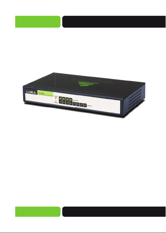
XFS-1084P
8-Port Fast Ethernet PoE Switch
Use the XFS-1084P to:
Cost-Effectively Expand a Wired Network
Deliver Power and Data for up to Four PoE-Enabled
Network Devices
Simplify the Installation of IP Security, VoIP and
other Network Applications

XFS-1084P
Quick Install Guide
Quick Install Guide
Model Number: XFS-1084P
8-Port Fast Ethernet PoE Switch
© 2014 Luxul. All Rights Reserved.
No part of this publication may be modified or adapted in any way,
for any purposes without permission in writing from Luxul. The material in this manual is subject to change without notice. Luxul reserves
the right to make changes to any product to improve reliability, function, or design. No license is granted, either expressly or by implication
or otherwise under any Luxul intellectual property rights. An implied
license only exists for equipment, circuits and subsystems contained
in this or any Luxul product.
DOCUMENT CONVENTIONS
The following graphical alerts are used to indicate notable situations:
NOTE: Tips, hints, or special requirements that you should
take note of.
CAUTION: Care is required. Disregarding a caution can
WARNING!: Indicates a condition or procedure that could
2
result in data loss or equipment malfunction.
result in personal injury or equipment damage.
a: 14203 Minuteman Drive, Ste 201, Draper, UT 84020-1685
p: 801-822-5450

Simply Connected
FCC COMPLIANCE
This device complies with Part 15 of the FCC Rules. Operation is
subject to the following two conditions: (1) this device may not cause
harmful interference, and (2) this device must accept any interference
received, including interference that may cause undesired operation.
CONTACT LUXUL
Sales
P: 801-822-5450
E: sales@luxul.com
Package Contents
Please check the contents carefully after you open the packing:
XFS-1084P 8-Port Fast Ethernet PoE Switch
Power Adapter and Cord
Quick Install Guide
If any of the listed items are missing or damaged, please contact
the reseller from whom you purchased the XFS-1084P for
return/replacement.
Technical Support
P: 801-822-5450
E: support@luxul.com
© Copyright 2014 Luxul. All rights reserved. Trademarks & Registered
Trademarks are property of respective holders.
3
XFS-1084P
Quick Install Guide
HARDWARE DESCRIPTION
Front Panel
The front panel of the XFS-1084P includes 8 Link/Activity LEDs, one
power LED, four PoE Status LEDs and one PoE Max LED. Please refer to
the detailed description of these indicators in Section 2.2 below.
XFS-1084P Front Panel View
LED Indicators
The LED indicators of the XFS-1084P include 8 Link/Activity LEDs,
one power LED, four PoE Status LEDs and one PoE Max LED. These
LED indicators show the operating status of the XFS-1084P and
each switch connection.
The following chart shows the LED indicators of the XFS-1084P along
with an explanation of the indicator’s properties:
4
a: 14203 Minuteman Drive, Ste 201, Draper, UT 84020-1685
p: 801-822-5450

Simply Connected
LED
Power
PoE Max
PoE Status
LINK/ACT
Color Status Description
Green ON The XFS-1084P is powered
OFF Check the DC power supply to
—
Red ON Maximum output wattage reached
Red Flashing Maximum output wattage
— OFF Maximum output wattage not
Green ON Delivering PoE power to
Green Flashing Can indicate an Ethernet cable
OFF No PoE power being delivered
Green ON Indicates the XFS-1084P is
Green Flashing Indicates the XFS-1084P is trans-
OFF Indicates the port is not con-
—
ensure proper connection to the
outlet and the XFS-1084P.
exceeded
reached
connected device
short or the connected device
is attempting to draw more than
15.4W
connected.
mitting/receiving data packets.
nected to a device.
© Copyright 2014 Luxul. All rights reserved. Trademarks & Registered
Trademarks are property of respective holders.
5

XFS-1084P
Quick Install Guide
Rear Panel Layout
The Rear Panel of the XFS-1084P includes eight 10/100Mbps RJ-45
Ethernet ports and one DC power port used for DC power input.
XFS-1084P Rear Panel View
CAUTION: Please use the included power supply. If a
different power supply is used, it could damage
the XFS-1084P
PREPARING FOR INSTALLATION
System Requirements
Ethernet Cables to connect the XFS-1084P to Ethernet
enabled devices
Power should be 48VDC @ 1.25A
6
a: 14203 Minuteman Drive, Ste 201, Draper, UT 84020-1685
p: 801-822-5450

Simply Connected
Installation Requirements
Install the XFS-1084P in a stable/safe place to avoid any
possible damage
Inspect the AC power cord to ensure that it is correctly
connected and undamaged
To avoid electric shock, DO NOT open the XFS-1084P housing
(no user serviceable parts inside). Opening the XFS-1084P will
void your warranty.
It is recommended that the Grounding connection to the outlet is
functioning properly and the XFS-1084P is positioned away from
direct sun light
Ensure there is sufficient space around the XFS-1084P for proper
ventilation and heat dissipation. It is recommended to have at least
4-6 inches around all sides.
Before Connecting to the Network
Before connecting the XFS-1084P to the network, please check the
following:
Determine placement location. Do not place any heavy articles on
the XFS-1084P.
Ensure there is adequate space for proper heat dissipation and
ventilation around the XFS-1084P.
Power socket should be within 4 feet of the XFS-1084P.
Check power adapter to confirm safe and secure connection.
© Copyright 2014 Luxul. All rights reserved. Trademarks & Registered
Trademarks are property of respective holders.
7

XFS-1084P
Quick Install Guide
XFS-1084P INSTALLATION
Connecting Devices
Use standard Ethernet CAT5, CAT5e or CAT6 cable to connect
the XFS-1084P to a device as described below. The XFS-1084P will
automatically adjust to the characteristics (speed/duplex) of the
device to which it is connected. The PoE function is autosensing.
As long as the powered device is 802.3af compliant, the switch will
provide power.
NOTE: Legacy PoE devices or 802.3at devices that need
more that 15.4Watts can not be powered by the
switch
87654321
Connecting the XFS-1084P to a Device
8
PoE
a: 14203 Minuteman Drive, Ste 201, Draper, UT 84020-1685
48V 1.25A
p: 801-822-5450

Simply Connected
When a device is properly connected, the Link/Activity LEDs for each
port lights up green. Please refer to the LED Indicators section for
defi nitions and troubleshooting.
Connecting to a Router or Other Switch
Connecting the XFS-1084P to a Router and Devices
When a device is properly connected, the Link/Activity LEDs for each
port lights up green. Please refer to the LED Indicators section for
defi nitions and troubleshooting.
NOTE: ports 1-4 are the POE ports and should not be used
for the uplink connection
© Copyright 2014 Luxul. All rights reserved. Trademarks & Registered
Trademarks are property of respective holders.
9

FCC Statement:
This equipment has been tested and found to comply with the limits for a Class
A digital device, pursuant to part 15 of the FCC Rules. These limits are designed
to provide reasonable protection against harmful interference in a residential
installation. This equipment uses and can radiate radio frequency energy, and if
not installed and used in accordance with the instructions may cause harmful
interference to radio communications. However; there is no guarantee that interference will not occur in a particular installation. If this equipment does cause
harmful interference to radio or television reception, which can be determined
by turning the equipment off and on, the user is encouraged to try to correct the
interference by one or more of the following measures:
Reorient or relocate the receiving antenna.
Increase the separation between the equipment and receiver.
Connect the equipment into an outlet on a circuit different from that to
which the receiver is connected.
Consult the dealer or an experienced radio/TV technician for help.
Hereby, Luxul, 14203 Minuteman Drive, Suite 201, Draper, Utah,
84020, declares that this Luxul XAP-1500 is in compliance with
the essential requirements and other relevant provisions of
Directive 1999/5/EC.
For a copy of this report send a self addressed stamped
envelope to:
Luxul CE, 14203 Minuteman Drive, Suite 201, Draper, Utah, 84020.
Information on this document supersedes all previous versions. Products
and documents subject to change without notice. Products may be
discontinued without notice.
LUX-QIG-XFS-1084P
0829140315
a: 14203 Minuteman Drive, Ste 201, Draper, UT 84020-1685
luxul.com | 801-822-5450
 Loading...