

ULTIMATE HIGH FIDELITY STEREO COMPONENT
SOLID STATE INTEGRATED AMPLIFIER
The latest creation from LUXMAN for those seeking real quality
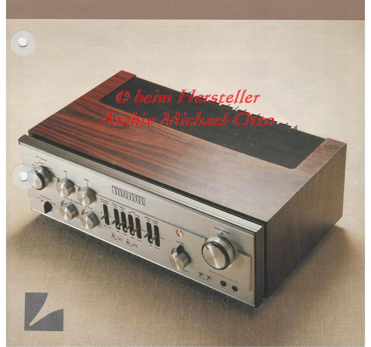
The L100 offers an astounding 110W RMS per channel with both channels driven into 8 ohms with no more than 0.05% total harmonic distortion at any frequencies from 20Hz – 20KHz. The world's 1st electronic "Touch-mute" circuit-ry allows you to reduce the volume instantly. LUXMAN's exclusive "Linear Equalizer" makes it possible to tailor reproduced sound subtly according to recording characteristics.
CIRCUIT DESCRIPTIONS
The equalizer section employs 1 stage differential amplification whole-stage direct-coupled circuit with cascode amplifier.
The differential amplification circuit adopted at the initial stage helps stabilize DC throughout the whole-stage direct-coupled circuit and at the same time improves linearity.
Cascode amplifiers are specially used at this differential amplifier and in the following stages to improve linearity at the treble range as well as stability and S/N ratio.
The final stage consists of an inverted Darlington push-pull circuit of class A operation, which keeps the signals harmless from load condition given by tape-deck etc. (to be connected at the later stage). Also at the various key points used are the constant current supply circuits to obtain better linearity from the transistors located on the signal path and to improve open loop-gain for perfect operation of the differential function.
At the intermediate amplifier and tone control amplifier section, too, we use whole-stage directcoupled circuits with cascode amplifier so as to ensure optimum linearity at the treble range and to improve stability and S/N ratio.
A constant current supply circuit at the output stage helps transistors play their role to the maximum capability.
LUXMAN's exclusive NF type tone control provided together with turn-over (roll-off) frequency selectors, which can be released if not necessary.
Independent filter circuits of sharp slope - 17d f. Oct. are provided for each cut-off requency so that simple and perfect switch-over can be realized as a whole circuit.)
Of course signals bypass these filter circuits if they are set at the "OFF" position.
This filter is of NF type utilizing emitter-follower, but composed by 2 transistors wherein one is used for emitter-follower while the other for the constant current purpose.
Therefore, optimum linearity can be obtained from the transistor of emitter-follower and high open loop-gain can be realized.
The main amplifier section employs 2-stage differential amplification whole-stage direct-coupled pure complementary OCL circuitry.
Special power and driver transistors for high power output are used at the output stage, and the final stage is composed by the parallel pushpull configuration, which makes it possible to yield a continuous output power of 110W per channel under 8-ohm loads.
The pre-driver stage uses a 2-stage differential amplifier, a kind of balanced type DC amplifier circuit which is of higher stability and immune from environment conditions such as fluctuation of supply voltage and ambient temperature changes.
The 2nd stage of this circuit is driven by the constant current for the purpose of voltage amplification.
In between the pre-driver stage of "class A" operation and the output stage of "class B" operation, an emitter-follower stage is placed with 2 transistors, which electrically insulates both stages and safeguards the former stage from possible infulence of impedance fluctuation caused by speaker load.
Thus negative feedback can be applied equally to the whole frequency range from the bass to the treble, which makes it possible to drive this amplifier at low distortion with good stability and small phase shift.
To prevent intermodulation distortion which is triggered by irregularity in "class A" operation on the pre-amplifier section and the pre-driver stage of the main amplifier section to be accompanied by fluctuation of current at the output stage of "class B" operation in the main amplifier section, the power transformer has completely separate windings for "class A" and "class B" operation, and perfect constant current circuits are provided at the power supply section to the "class A" operational portion.
And also 2 computor-grade giant capacitors of 15,000 µF are used for the power supply filtering to the output stage.
Other complex protection circuits are added to safeguard not only the amplifier but your loud-speakers from accidental damages.
A multing circuit which eliminates unpleasant thumps at the time of switching serves to protect loudspeaker against damage.
Other useful features are provided such as a volume attenuator, speaker selector, phono input sensitivity and impedance selectors, tape-dubbing circuit etc.
The L100 offers the ultimate in precision and elegance.
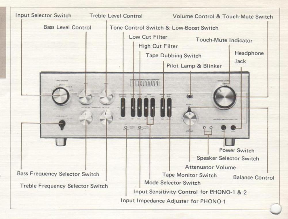
OPERATIONAL FEATURES
Although recordings are equalized in accordance
In addition, differences in listening environment controls cannot correct because of their wide range and overlapping crossover characteristics. The Linear Equalizer control provides a new form of tonal compensation specifically intended for subtly augmenting regular tone controls.
cy response is achieved.
Switched to either of the two "up-tilt" positions the entire response curve is rotated about a 1KHz fixed axis so as to linearly increase treble response while simultaneously decreasing bass response. Conversely, selection of one of the "down-tilt" positions rotates the response curve in a clockwise direction, providing a gradual decrease of treble response and simultaneous increase of bass re-
Degree of slope for either positive or negative setresponse curve maintains complete linearity from 50Hz to above 10KHz, unlike the curvature in reonse normally associated with ordinary tone
Atrols. Combined use of the Linear Equalizer and conventional tone controls provides a degree of tonal other tone control arrangement presently available.
Because of the inherently linear nature of this distortion at any of its settings.
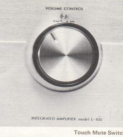
Touch Mute Switch
Most of the current amplifiers are equipped with
Usual case is to do ON-OFF operation med ly by a switch, while this model has adopted new electronic Touch-Mute system.
A slight touch on this knob ensures operation To operate this muting circuitry touch by hand the center metal part of the main volume and the gain may be reduced by 20dB and the volume is reduced to 1/10.
Cancellation is possible by touching the outer al part of the knob just like the case of normal operation of the main volume.
The variable resistor of this control has a logarith-
In the attenuation characteristics of A type, the turning angle is proportionate to the attenuation degree (dB), the dB value and the volume audible proportion to the sound volume felt by human ears.
The increaseing degree of volume is felt quite natural as the control is turned in the clockwise
A precision detent-volume of high-grade attenuator type ensures a precise adjustment of volume on both right and left channels.
Input Impedance Adjuster:
The PHONO-1 input terminals are coupled with Impedance Adjustor
Except for a special low impedance type cartridge almost all currently marketed cartridges of MMabout 50K ohms.
It is known that variation of the load impedance
high impedance load causes a peak in the treble
The degree of such effect is not the same with different cartridges, but generally a cartridge having a higher output impedance tends to be more deli-
It is therefore necessary that selection of a proper input impedance is made with this adjustor.
The adjustment of Input Sensitivity is done by a potentiometer, and free adjustment is feasible be-
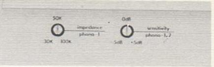
Each position of the 30Kohms, 50Kohms and 100Kohms has click stopper for easy identifica-
Input Sensitivity Adjuster:
There are various types of cartridges: magnetic type, photo-electric type, electro-static type and piezo-electric type.
Most predominant is the magnetic type which includes MM (Moving Magnet), MI (Moving Iron), IM (Induced Magnet) and MC (Moving Coil). The PHONO terminals of this amplifier are designed to match with these types of magnetic cartridges, but a cartridge of low output level (output voltage 0.01 to 0.1mV) cannot be directly con-
Input Sensitivity adjustment is feasible both at Free adjustment of ±5dB is possible in case the input sensitivity of 3mV is regarded as 0dB. That is, the most suitable sensitivity to the cartridge can be obtained between some 1.7mV and 5mV in view of the fact that the sensitivity at ±5dB is some 1.7mV and at -5dB is 5mV.
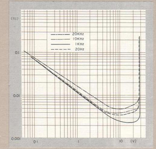
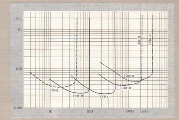
MAIN AMP: FREQUENCY RESPONSE beima loads, 0dB = 1W) urgent occasion as the phone-call during remoduc-tion. MAIN AMP: POWER VS. TOTAL HARMONIC DISTORTION
© beim Hersteller Archiv Michael-Otto
We know the true measurements of minimum performance standards of a quality amplifier must be
However, these figures are not the only require ments.
Despite every effort to make amplifier design a pure science one amplifier among many with similar absolute specifications can still have,
The reason: there are more comprehensive theories of amplifier design which account for such prorelate to statements of power
Whatever the scientific theory, LUX conducts the most detailed listening test with engineers and musicians in different fields to ensure that LUX amplifiers sound best apart from what is considered good in brochures
To LUX, sound is not only a science but an art. Listen to the ultimate difference at your nearest audio shop.
SPECIFICATIONS < MAIN AMPLIFIER SECTION >
| Power Output: | 110 watts minimum continous per channel, into 8-ohm loads, from 20Hz to 20,000Hz, at no more than 0.05% total harmonic distortion |
| Rated I.M.: | 0.05% (60 : 7KHz'= 4 : 1, 8 ohm loads, 110W/ch) |
| Frequency Response: | 5 – 50,000Hz (±1dB) |
| Input Sensitivity: | 910mV 8 ohms, 110W |
| Input Impedance: | 33 Kohms |
| Residual Hum & Noise: | -90dB |
| Damping Factor: | 50 (8 ohm loads) |
| < PRE AMPLIFIER SECTI | ON > |
| Output Voltage: | Typ. 910mV, Max. 12V |
| Frequency Response: | 5 – 50,000Hz (–1dB) |
| Total Harmonic Distortion: | No more than 0.007% (1 KHz, 1V) |
| Input Sensitivity: | 3mV (phono-1 & 2, Gain 0dB) 180mV (tuner, 180mV (aux-1 & 2) |
| Input Impedance: | 30 K ohms – 100 Kohms (variable) |
| S/R Ratio: | No less than 65dB (phono) |
| Phono Overload Voltage: | 450mV (1 KHz, RMS) |
| R.I.A.A. Equalization: | ±0.2dB |
| Residual Hum & Noise: | No more than 40µV |
| Cross Talk: | No more than -60dB |
| Power Consumption: | 400W at Max. power output |
| Additional Features | Touch mute function, Linear equalizer etc. |
| Dimensions: | 485(W) x 350(D) x 175(H)mm (19-1/8" x 13-3/4" x 6-7/8") |
| Weight: | Net. 19kgs (42 lbs.) Gross 21kgs (46 lbs.) |
Specifications and appearance design subject to possible change without notice
LUX CORPORATION, JAPAN HEAD OFFICE & FACTORY 1-8-31, NAGAHASHI, NISHINARI-KU, OSAKA PHONE: 632-0031 CABLE: LU
Printed in Japar


 Loading...