


X-70A 3D
INSTALLATION AND OPERATION
INSTRUCTIONS

 ® LOWRANCE
ELECTRONICS, INC.

TABLE OF CONTENTS |
|
INTRODUCTION .............................................................................................................................. |
1 |
SPECIFICATIONS ........................................................................................................................... |
1 |
INSTALLATION ............................................................................................................................... |
1 |
TRANSDUCER ............................................................................................................................ |
1 |
SONAR UNIT ............................................................................................................................... |
5 |
POWER CONNECTIONS ............................................................................................................ |
6 |
KEYBOARD BASICS .................................................................................................................. |
7 |
DISPLAY .......................................................................................................................................... |
8 |
MODES OF OPERATION ................................................................................................................ |
9 |
OPERATION ................................................................................................................................... |
11 |
AUTOMATIC ............................................................................................................................... |
11 |
SENSITIVITY .............................................................................................................................. |
11 |
3D OPERATION ............................................................................................................................. |
12 |
3D RANGE ................................................................................................................................. |
12 |
3D ZOOM ................................................................................................................................... |
12 |
3D VARIVIEW™ ................................................................................................................... ...... |
13 |
2D OPERATION ............................................................................................................................. |
15 |
2D TRANSDUCER ELEMENT SELECTION .............................................................................. |
15 |
2D RANGE ................................................................................................................................. |
15 |
2D RANGE - Upper and Lower Limits ........................................................................................ |
16 |
2D ZOOM - Automatic Operation ................................................................................................ |
17 |
2D ZOOM - Manual Operation .................................................................................................... |
18 |
BOTTOM DEPTH VIEW ................................................................................................................. |
18 |
FASTRAK™ ....................................................................................................................... ............ |
19 |
MENU - PAGE 1 ............................................................................................................................. |
20 |
STOP CHART ............................................................................................................................. |
20 |
ALARMS ..................................................................................................................................... |
20 |
DEPTH ALARMS ..................................................................................................................... |
21 |
ZONE ALARM ......................................................................................................................... |
22 |
FISH ALARM ........................................................................................................................... |
23 |
MUTE ALARM ......................................................................................................................... |
23 |
FISH I.D. ..................................................................................................................................... |
23 |
DISPLAY CONTRAST ................................................................................................................ |
24 |
2D VIEW OPTIONS .................................................................................................................... |
25 |
DIGITAL BOX OPTIONS ......................................................................................................... |
25 |
DIGITAL SONAR ..................................................................................................................... |
26 |
2D FASTRAK™ BAR .............................................................................................................. |
26 |
ZOOM BAR .............................................................................................................................. |
27 |
ZONE ALARM BAR ................................................................................................................. |
27 |
CHART CURSOR .................................................................................................................... |
27 |
MENU - PAGE 2 ............................................................................................................................. |
28 |
GRAYLINE® .............................................................................................................................. |
28 |
CHART SPEED .......................................................................................................................... |
29 |
ADJUST BACK LIGHT LEVEL ................................................................................................... |
29 |
SPEAKER VOLUME .................................................................................................................. |
30 |
UNITS OF MEASURE ................................................................................................................ |
30 |
MENU - PAGE 3 ............................................................................................................................. |
31 |
SURFACE CLARITY CONTROL ................................................................................................ |
31 |
ASP (Advanced Signal Processing) ............................................................................................ |
31 |
FISHTRACK™ ..................................................................................................................... ....... |
32 |
ADJUST TEMPERATURE GRAPH ............................................................................................ |
32 |
RESET DISTANCE LOG ............................................................................................................ |
33 |
MENU - PAGE 4 ............................................................................................................................. |
33 |
3D ENHANCE ............................................................................................................................ |
33 |
3D SIMULATOR ......................................................................................................................... |
34 |
3D DISTANCE MARKERS ......................................................................................................... |
34 |
TROUBLESHOOTING .................................................................................................................... |
35 |
NOISE ........................................................................................................................................ |
35 |
MISSING PARTS ............................................................................................................................ |
38 |
LOWRANCE FULL ONE YEAR WARRANTY ................................................................................ |
39 |
UPS RETURN SERVICE ................................................................................................................ |
40 |
ACCESSORY ORDERING INFORMATION ................................................................................... |
41 |
Copyright © 1994, Lowrance Electronics, Inc. All rights reserved.
All features and specifications subject to change without notice. All screens in this manual are simulated.

INTRODUCTION
Thank you for purchasing an X-70A 3D. Its adjustable VariView™ 3D perspective lets you rotate the underwater picture to accommodate specific viewing needs. In addition to the 3D views, the X-70A 3D also gives you outstanding 2D detail using either the supplied 384 kHz transducer or an optional 192 kHz transducer.
SPECIFICATIONS
Dimensions ..................................... |
5 7/8" H x 7 3/4"W x 3 7/8"D |
Transmitter Frequency .................... |
384 kHz and 192 kHz |
Transmitter Power ........................... |
3000 watts (peak-to-peak, typical) |
|
375 watts (RMS, typical) |
Display ............................................ |
Supertwist LCD |
|
200 vertical x 320 horizontal |
|
64,000 total pixels |
NOTICE!
The storage temperature for your unit is from -4 degrees to +167 degrees Fahrenheit (-20 degrees to +75 degrees Celsius). Extended storage in temperatures higher or lower than specified will damage the liquid crystal display. This type of damage is not covered by the warranty.
INSTALLATION
TOOLS AND HARDWARE YOU WILL NEED
Screwdriver
Four #10 screws with flat washers or up to 1/4" screws (to attach gimbal bracket to dash)
Hand-held drill with a 5/32" drill bit Marine grade caulking compound
TRANSDUCER INSTALLATION:
The HS-3D4 supplied with your X-70A 3D is a 384 kHz, 4 element, highspeed, transom mount transducer. It can be installed on any outboard or stern-drive (inboard-outboard) powered boat.The built-in “kick-up” bracket helps prevent damage if the transducer strikes an object while the boat is moving. If the transducer does “kick-up”, it can be pushed back in place without tools.
Read this section carefully before attempting the installation. Determine the best mounting location for your boat. Remember, the transducer location is the most critical part of a sonar installation. If it isn’t done properly, the sonar can’t perform to it’s designed potential.
1
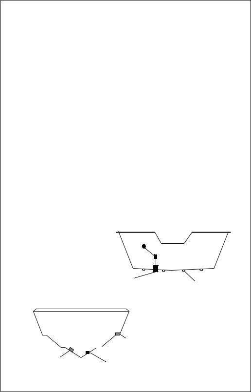
Transducer Location
1.The transducer must be placed in a location that has a smooth flow of water at all times. If the transducer is not placed in a smooth flow of water, interference will show on the sonar’s display in the form of random lines or dots whenever the boat is moving and can completely mask the sonar image at high speed.
2.The transducer should be installed with its face pointing straight down, if possible.
3.Make certain the chosen location doesn’t interfere with the boat’s trailer. Also, don’t mount it closer than about one foot from the engine’s lower unit. This will prevent cavitation interference with the propeller. Typically, the transducer should be mounted as far down on the transom as possible. This increases the chance that it will remain in the water at high speed or sharp turns, and reduces the possibility of air bubble interference (cavitation).
4.Don’t mount the transducer directly behind strakes or ribs on the bottom of the hull. Typically, a good location on aluminum boats is between the ribs closest to the engine.The port (left) side of the transom is preferred for mounting the transducer, however, if this is not possible, the starboard (right) side can be used, usually with good results.
CAUTION!
CLAMP THE TRANSDUCER CABLE TO
TRANSOM NEAR THE TRANSDUCER. THIS
WILL HELP PREVENT THE TRANSDUCER 
FROM ENTERING THE BOAT IF IT IS
KNOCKED OFF AT HIGH SPEED.
GOOD LOCATION |
RIBS ON |
|
ALUMINUM
BOATS
POOR LOCATION
POOR ANGLE
GOOD LOCATION
2
Transducer Assembly and Mounting
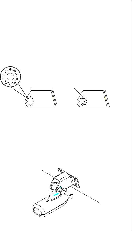
The best way to install this transducer is to loosely assemble all of the parts first, place the transducer’s bracket against the transom and see if you can move the transducer so that it’s parallel with the ground.
1.Press the two small plastic ratchets into the sides of the metal bracket as shown below. Notice there are letters molded into each ratchet. Place each ratchet into the bracket with the letter “A” aligned with the dot stamped into the metal bracket.This position sets the transducer’s coarse angle adjustment for a fourteen (14) degree transom. Most outboard and stern-drive transoms have a fourteen degree angle.
DOT
2.Slide the transducer between the two ratchets. Temporally slide the bolt though the transducer assembly and hold it against the transom. Looking at the transducer from the side, check to see if it will adjust so that its face is parallel to the ground. If it does, then the “A” position is correct for your hull. If the transducer’s face isn’t parallel with the ground, remove the transducer and ratchets from the bracket. Place the ratchets into the holes in the bracket with the letter “B” aligned with the dot stamped in the bracket. Reassemble the transducer and bracket and place them against the transom. Again, check to see if you can move the transducer so it’s parallel with the ground. If it does, then go to step 3. If it doesn’t, repeat step 2, but use a different letter until you can place the transducer on the transom correctly.
3

METAL NUT WASHER
RUBBER
WASHERS
3.Once you determine the correct position for the ratchets, assemble the transducer as shown at left. Do not tighten the lock
nut at this time.
METAL
WASHER
BOLT
4.Hold the transducer and bracket assembly against the transom. The transducer should be roughly parallel to the ground.The bottom of the transducer bracket should be in line with the bottom of the hull. Don't let the bracket extend below the hull! Mark the center of the slots for the mounting holes. Drill two 5/32" holes in the marked locations for the #10 screws supplied with the transducer.
TRANSOM
SIDE VIEW
5.Attach the transducer to the transom. Slide the transducer up or down until it’s aligned properly on the transom as shown above. Tighten the bracket’s mounting screws. Adjust the transducer so that it’s parallel to the ground and tighten the lock nut until it touches the flat washer, then add 1/4 turn. Don’t over tighten the lock nut! If you do, the transducer won’t “kick-up” if it strikes an object in the water.
4
6.Route the transducer cable to the sonar unit. If possible, route the transducer cable away from other wiring on the boat. Electrical noise from the engine’s wiring, bilge pumps, VHF radio wires and cables, and aerators can be picked up by the sonar. Use caution when routing the transducer cable around these wires.
IMPORTANT!
Clamp the transducer cable to the transom close to the transducer. This can prevent the transducer from entering the boat if it is knocked off at high speed.
7.Make a test run to determine the results. If the bottom is lost at high speed, or if noise appears on the display, try sliding the transducer bracket down. This puts the transducer deeper into the water, hopefully below the turbulence causing the noise. Do not allow the transducer bracket to go below the bottom of the hull!
SONAR UNIT MOUNTING
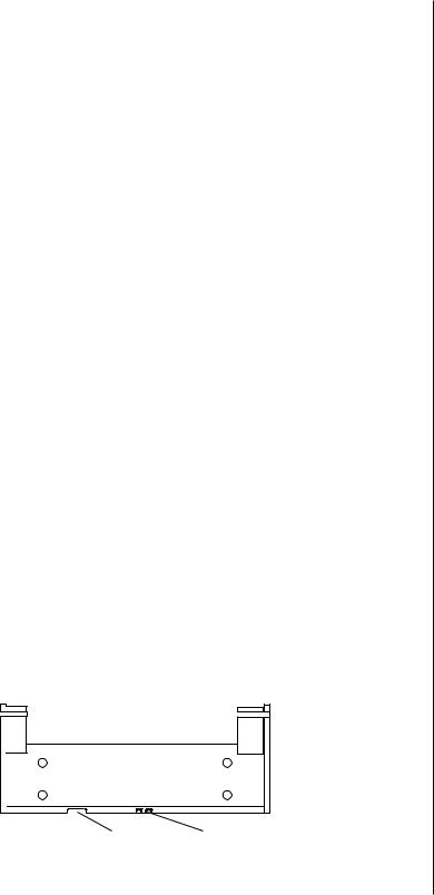
Install the X-70A 3D in any convenient location, provided there is clearance behind the unit when it is tilted for the best viewing angle. Holes in the bracket base allow wood screw or through-bolt mounting. Make certain there is enough room behind the unit to attach the power and transducer cables.
Using the bracket as a template, mark the dash for the mounting holes, then make a mark in the center of the bracket location for the cable hole. If you want the smallest possible hole for the power and transducer cables in the dash, install the transducer first, then route the cable to the desired location. The smallest hole that will pass one power or transducer plug is 5/8". After the hole is drilled, pass the transducer connector up through the hole first, then pass the power cable down through it.
After routing the cables, fill the hole with a good marine sealing compound. Place the bracket over the hole and route the cables through the slot in the back of the bracket. Break out one of the other slots for the transducer cable. Screw the bracket to the dash.
FRONT
SLOT |
BREAK OUT SLOT |
5
POWER CONNECTIONS
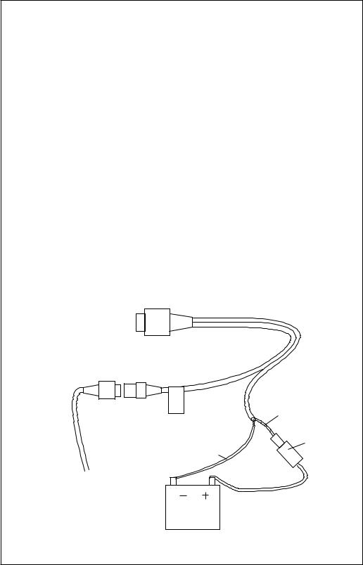
The X-70A 3D works from a twelve-volt battery system. For the best results, attach the power cable directly to the battery. You can attach the power cable to an accessory or power buss, however you may have problems with electrical interference. Therefore, it’s safer to go ahead and attach the power cable directly to the battery. If the cable isn’t long enough to reach the battery, splice #18 gauge wire onto it. The power cable has two wires, which are red and black. Red is the positive lead, black is negative or ground. Make certain to attach the in-line fuse holder to the red lead as close to the power source as possible. For example, if you have to extend the power cable to the battery or power buss, attach one end of the fuse holder directly to the battery or power buss.This will protect both the unit and the power cable in the event a short occurs.
IMPORTANT!
Do not use this product without a 3-amp fuse wired into the power cable! Failure to use a 3-amp fuse will void your warranty.
If you’ve purchased the optional ST-T speed/temperature sensor, install it according to the instructions included with the sensor. Route its cable to the X-70A 3D’s power cable and plug it into the connector marked “SPEED/ TEMP CABLE”.
TO X-70A 3D'S
POWER CONNECTOR
|
SPEED/ |
RED |
|
TEMP |
|
|
CABLE |
|
|
|
WIRE |
|
|
3 amp |
|
BLACK |
FUSE |
|
WIRE |
|
TO |
|
|
SPEED/ |
|
|
TEMP |
|
|
SENSOR |
12 VOLT |
|
|
BATTERY |
|
6
KEYBOARD
The keyboard is arranged for convenient operation. A ten-key keypad on the right side of the screen lets you enter numbers. Arrow keys beneath the keypad are used to adjust features. The keys in the left column are used to select menu features.The keys along the bottom of the screen let you select the basic sonar functions.
SENS Press this key to adjust the unit’s sensitivity.
RANGE This key lets you adjust the range shown on the display.
ZOOM This switches the chart between two times and four times zoom.
AUTO This turns the automatic feature off or on.
WINDOWS This key lets you select the different display modes.
MENU Press this key to show the menus.
ARROW KEYS These keys are used to make adjustments on menus.
ON The “On” key turns the unit on and also turns the backlights on.
OFF Press and HOLD the Off key to turn the X-70A 3D off.
FULL CHART This key switches the digital box between small and large digits when the 2D chart is displayed.
LOWRANCE |
X70A 3D |
||
FULL CHART |
1 |
2 |
3 |
|
|
|
|
|
4 |
5 |
6 |
|
7 |
8 |
9 |
|
CLR 0 |
ENT |
|
WINDOWS M E N U
OFF |
O N |
SENS |
RANGE |
Z O O M AUTO |
7
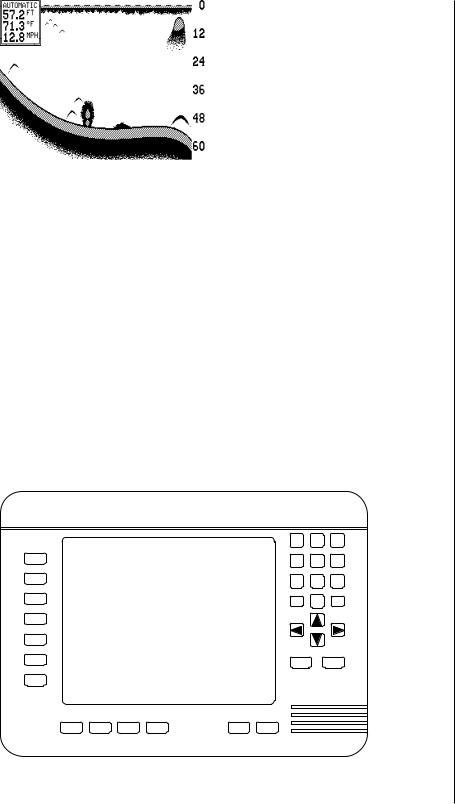
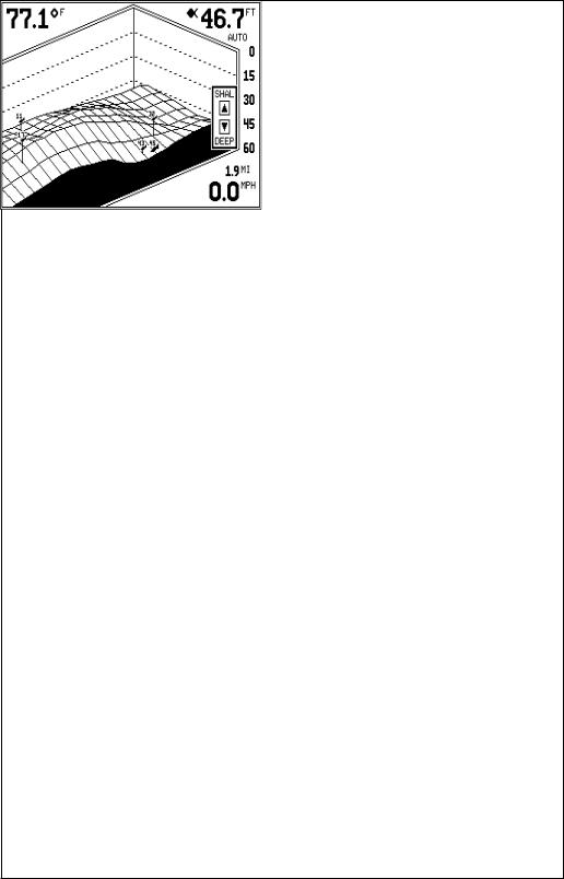
DISPLAY - General
When the X-70A 3D is first turned on, the display looks similar to the one below. The 3D screen scrolls from right to left, with the scale on the right side of the screen. The current depth beneath the transducer shows in the upper right corner of the display. A fish symbol to the left of the depth shows that the Fish ID feature is on. The word “AUTO” signifies that the automatic function is on, keeping the bottom on the display at all times. If the computer identifies targets as fish, one of four fish symbols appear on the screen, depending on the size of the target. Numbers above the fish symbol tell you the depth of the target. This feature is called “FishTrack”.
The lights are on for a few seconds when the X-70A 3D is turned on. Menus appear at the same time. To leave the lights on, press the ON key. This key controls the back lights. If you don’t want the lights on, wait a few seconds and they will automatically turn themselves off. The menus will also disappear after a few seconds, or you can press the CLEAR key to erase them.
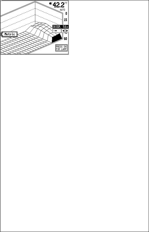
The Metric and Display menu labels work the same way. Press the key adjacent to the Metric label to change the depth from feet to meters. This also changes the temperature display to degrees Celsius, speed to knots, and log to kilometers.
The Display menu on the screen's right side lets you adjust the display’s for the best contrast. Press the left arrow key to decrease the contrast, right arrow key to increase it.
The X-70A 3D automatically detects the speed/temperature sensor. If the sensor is attached to the unit, speed, temperature, and distance log automatically appear on the display. Distance markers also appear on the
8
screen, showing the distance behind the boat. If the speed/temperature sensor is not plugged into the X-70A 3D, then none of these will show.
MODES OF OPERATION
The X-70A 3D shows a sonar picture of the underwater world in 3D, 2D, Bottom Depth View, and FasTrack™ modes. The 2D and Bottom Depth Views can use either the 384
or 192 kHz transducer (if the optional 192 kHz transducer is attached). The 3D mode is always 384 kHz. To switch between the different modes, first press the WINDOWS key. Press a key on the left side of the screen to choose the desired mode. Press the CLR key to exit this menu.
In the 3D mode shown at right,
the bottom is represented by a “wire-frame” model. Only the bottom and fish symbols show in this mode. Structure, weeds, thermoclines, etc. will not show.
The X-70A 3D uses a 384 kHz transducer with four elements. The digital depth display shows the bottom depth from the middle transducer elements. If it loses the signal from any element, a box with the word “LOST” appears over the corresponding area on the display. This means the unit cannot receive an echo from that element. This could be due to a large drop-off, noise or other natural phenomenon.
The 2D mode looks like a conventional sonar display as shown below. The bottom echo scrolls from right to left. The range displays on the right side of the screen. The digital
bottom depth shows in the upper left corner.When the X- 70A 3D is put into the 2D 384 kHz mode, the two center transducer elements are in use. The two outer elements are turned off. You can select the elements from a menu discussed in a later section. The 2D 192 kHz transducer has only one element.
9
All 2D modes show the bottom signal, structure, thermoclines, fish (both with and without the Fish ID feature), baitfish schools, and more. The 3D view shows a 3D representation of the bottom, with Fish ID symbols only. The 2D mode shows more information, the 3D mode makes it easier to visualize the bottom contour.
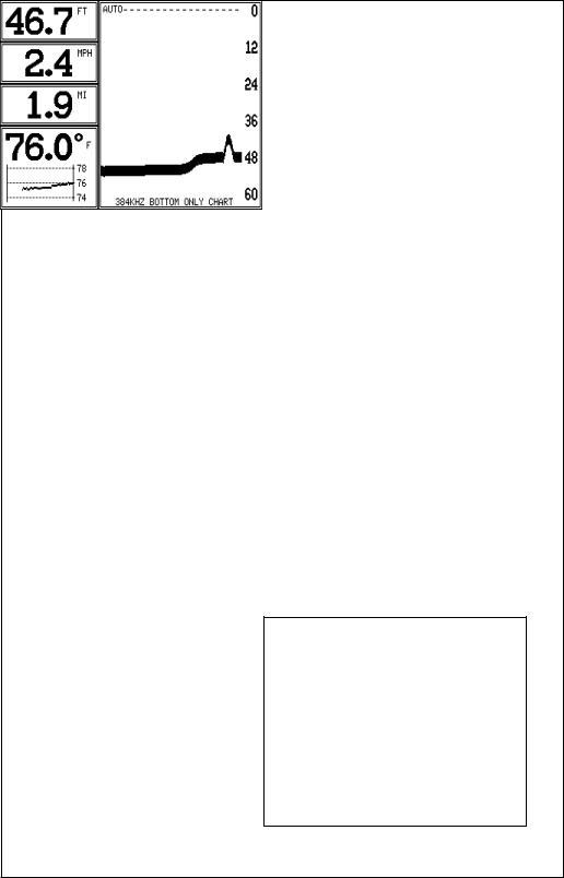
The Bottom Depth View as shown at right displays the depth at the top of the display in large digits. The graph scrolls at high speed. Note that this graph only shows the bottom signal. No structure, fish signals, or other echoes show on this display. This feature is available using either frequency transducer. (384 Bottom or 192 Bottom)
The 3D FasTrak screen converts echoes from all four transducer elements into short horizontal lines. Typically, the thicker the bar, the stronger the echo. This screen is updated rapidly, giving you flasher-like performance. You can view echoes from any or all elements on this screen.
DIGITAL BOX
A box containing the digital displays appears in the upper left corner of the display when a 2D display is enabled. You can switch the size of the display from normal to large by pressing the FULL CHART key or by pressing the up or down arrow keys on the selection menu.
10
OPERATION
The Automatic and Sensitivity features used on the X-70A 3D are the same for all modes of operation. This section will explain these features. For information on features specific to different modes, see the 2D or 3D operation sections.
AUTOMATIC
The X-70A 3D adjusts the sensitivity and range to keep a detailed bottom signal on the display when the automatic feature is on. This is enabled when the unit is first turned on. You can turn this feature off to gain greater control over the adjustments and features of this unit.
To turn automatic off, press the AUTO key. A screen similar to the one above appears. Now press the AUTO key again. This moves the check mark from the “AUTO” box to “MAN”. Press the CLR (clear) key to erase the menu.To switch back to manual, repeat the above steps, but move the check mark to the “AUTO” box using the AUTO key.
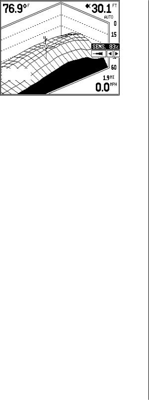
SENSITIVITY
The sensitivity control adjusts the receiver’s ability to show echoes. If it’s adjusted properly, the sonar unit shows not only the bottom, but targets (such as fish) with little or no noise. If the sensitivity is turned too low, no fish signals will show, and you will lose the bottom signal in fairly shallow water.
When the X-70A 3D is in the automatic mode, the computer inside adjusts the sensitivity for the best setting.You can override this setting, adding or subtracting the amount of sensitivity the computer uses. You can also take complete control of the sensitivity level when the unit is in the manual mode.
11
To adjust the sensitivity, press the SENS key. A menu appears on the right side of the screen as shown on the previous page. Press the right arrow key to increase it, the left arrow key to decrease it. When you have it changed to the desired level, press the CLR key to erase the menu or wait a few seconds for it to automatically clear.
3D OPERATION
When the X-70A 3D is in the 3D mode, the Fish ID feature is always on (unless you turn it off). FishTrack (the depth numbers above the fish symbols) shows you the depth of the fish symbol and can be turned off, if desired. See the FishTrack section in this manual for more information.
3D RANGE
The range is set by the unit as long as it’s in the auto mode. However, you can adjust the range slightly when automatic is on. The unit won’t let you move the bottom off the screen, and it will correct the range once the bottom begins to go off the screen. When the unit is in the manual mode, you can set the range to any that’s available.
To change the range on the X- 70A 3D, first press the RANGE key. A screen similar to the one at right appears. Simply press the down arrow key to increase the range or the up arrow key to decrease it. When the desired range is chosen, wait a few seconds and the menu will automatically disappear from the screen or press the CLR key to erase it.
The X-70A 3D uses the following ranges: 0 - 5, 10, 20, 40, 60, 80, 100, 150, 200, 300, 400, 500, 700, and 900 feet.
3D ZOOM
The zoom feature enlarges all echoes on the screen, making them easier to see. This feature works in automatic or the manual mode. (Note: If the unit is in the 3D automatic mode and the zoom feature is turned on, the unit will not change the range to a shallower setting. If the bottom signal goes shallower than the zoom range, the X-70A 3D will simply show a flat bottom signal at the shallowest range shown on the display. For example, if you have a zoom range from 45 to 60 feet, and the bottom rises to 30
12
 Loading...