


LWX-1 WEATHER
Sirius Audio & Weather Antenna
Installation & Operation Manual
Copyright © 2009 Navico
All Right Reserved.
No part of this manual may be copied, reproduced, republished, transmitted or distributed for any purpose, without prior written consent of Navico.
LWX-1 is a trademark and Lowrance® and Navico® are registered trademarks of Navico, Inc.
SIRIUS is a registered trademark of SIRIUS.
Navico may find it necessary to change or end our policies, regulations and special offers at any time. We reserve the right to do so without notice.All features and specifications subject to change without notice.
For user manuals and the most current information on this product, its operation and accessories, visit our web site:
www.lowrance.com
Navico
12000 E Skelly Dr.
Tulsa, OK 74128-2486
(800) 324-1356
Canada (800) 661-3983 or (905) 629-1614
Contents |
|
Installation............................................................................. |
2 |
Mast Mount Installation.................................................................... |
5 |
Flush Mount Through-Deck Installation........................................... |
6 |
Flush Mount Above-Deck Installation............................................... |
7 |
Interface Module Installation............................................................ |
8 |
SIRIUS Activation................................................................ |
10 |
Operation ............................................................................ |
13 |
Manual Conventions...................................................................... |
13 |
Audio.................................................................................... |
14 |
SIRIUS Status................................................................................ |
15 |
Media Bar Controls................................................................................... |
15 |
SIRIUS Audio Menu....................................................................... |
16 |
Listening to SIRIUS audio......................................................................... |
16 |
Change Lock Code................................................................................... |
19 |
Volume...................................................................................................... |
19 |
Weather................................................................................ |
20 |
Overlay........................................................................................... |
20 |
Displaying Weather on Chart page........................................................... |
20 |
Weather options menu................................................................... |
21 |
Precipitation................................................................................... |
21 |
Map Scale...................................................................................... |
21 |
Weather Alarms......................................................................................... |
23 |
City Forecast.......................................................................................................... |
23 |
Animate..................................................................................................... |
26 |
Transparency............................................................................................ |
27 |
SIRIUS Subscription Levels........................................................... |
27 |
1

Installation
Thank you for purchasing the LWX-1 SIRIUS Audio/Weather Antenna. This manual documents installation, activation and how to use SIRIUS features with an HDS display unit.
This section covers the installation of the Lowrance LWX-1 and SIRIUS subscription activation.
CAUTION: For the LWX-1 to work properly with your HDS product,
!you will need code version 2.0 or greater. Visit www.lowrance.com for instructions on how to download/install software updates.
LWX-1 package includes:
Main Components:
|
Main Components |
||
Antenna Receiver (AR) |
|
IM Power Cable |
|
pre-configured for a mast mount |
|||
|
|||
AR Interconnect Cable |
|
IM Network Cable |
|
Interface Module (IM) |
|
|
|
|
|
|
|
|
|
||
|
Mounting Components |
||
AR Gasket (1) |
|
IM Mounting Screws (2) |
|
AR Mounting Screws (4) |
|
AR Screw Caps (5) — one extra |
|
2
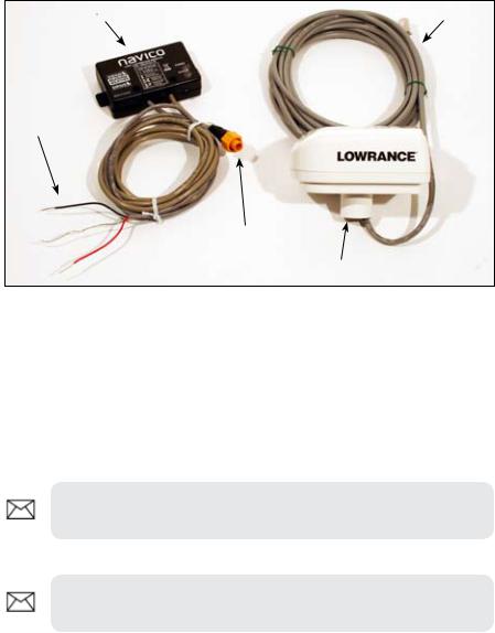
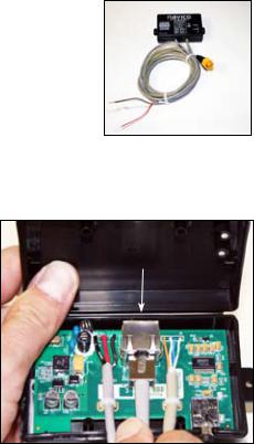
Interface module |
RJ45 Cable |
Power wires
Ethernet connector
LWX-1 Antenna
LWX-1 Installation Options
The LWX-1 can be mounted in three configurations:
1.Mast Mount
2.Flush Mount
3.AR Flush Mount
NOTE: When installing, make sure the RJ45 Interconnect cable will fit properly through any ratchet mounts or other boat hardware.
NOTE: Planning a cable route in advance could prevent multiple cable pulls, decreasing the chance of damaging the RJ45 connector.
3
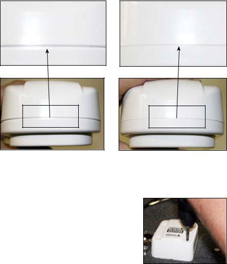
WARNING
AR Bolts in place, but module is not tightly sealed.
AR Bolts are tightened securely; module is sealed tight.
Tightening AR bolts
No matter how the LWX-1 antenna is installed, you will have to loosen or remove the AR bolts. After mounting the LWX-1, make sure the AR bolts have been tightened securely. The AR bolts MUST be tightened to prevent water from getting into the LWX-1 housing.
4

Mast Mount Installation
The LWX-1Antenna Receiver (AR) is shipped pre-configured for a mast mount.
Loosening LWX-1 AR Bolts. |
Insert RJ45 Interconnect Cable into |
|
mast/pole mount. |
To use LWX-1 Mast Mount Installation:
1.Loosen the four LWX-1 AR Bolts & Nuts. The circular mast boot on the bottom of the LWX-1 will loosen, allowing it to turn.
2.Insert the RJ45 Interconnect Cable into the mast/pole mount and route it to the Interface Module.
3.Move the LWX-1 antenna into the desired position and screw the mast boot onto the mast/pole. The
LWX-1 mast mount is designed for occasional hand alignment, so handtighten as much as possible – DO NOT OVER-TIGHTEN.
4.With the LWX-1 installed, move it in to
the desired position and re-tighten the |
|
|
Hand tighten LWX-1 onto |
||
four AR Bolt & Nuts. |
||
mast mount. |
||
|
5.Use the four white screw caps to cover the bolt holes on top of the LWX-1 cover .
5
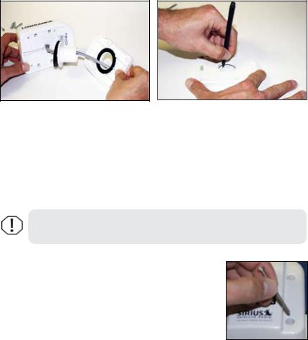
Flush Mount Through-Deck Installation
You will route the RJ45 cable through the deck in this installation.
Remove AR Mast mount. |
Use Mast mount panel as a template. |
To use Flush Mount through-deck installation:
1.Remove the four LWX-1 AR Bolts & Nuts and then remove the preconfigured mast mount.
2.Use the mast mount panel as a template to mark where the mounting screws and RJ45 interconnect cable holes will be drilled.
WARNING: The LWX-1 AR cover and AR base are factory fitted.
DO NOT ATTEMPT TO SEPARATE THEM.
3.Drill the 1/32” starter holes for the mounting screws and a 1/2” hole for the RJ45 interconnect cable.
4.Insert the interconnect cable through the deck and pull it through.
5.Mount the LWX-1 to the deck using the four supplied machine screws.
6.Use the four white screw caps to cover the bolt holes on top of the LWX-1 cover.
Insert Flush Mount
machine screw
6
Flush Mount Above-Deck Installation
This installation differs from the Flush Mount through-deck Installation in that the cable is routed out of the back of the LWX-1 Antenna, instead of through the deck.
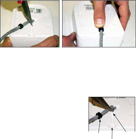
Breaking away the channel stop.
Insert rubber boot into boot inset.
To use Flush Mount above-deck installation:
1.With a pair of needle-nose pliers break away/remove the channel stop, so the interconnect cable can fit flush in the cable channel on the bottom of the LWX-1.
2.Insert the RJ45 interconnect cable into the cable channel.
3.Ensure the rubber boot on the Interconnect Cable is firmly in theAR Rubber Boot Inset so it is flush with the
bottom of the LWX-1 Base.
4.Use the mast pound panel to mark
where the machine screws will be drilled. Drill 1/32” starter holes.
5. Make sure the interconnect cable is |
|
|
|
|
secured in the cable channel and then |
|
|
|
|
Rubber |
Channel |
|||
mount the LWX-1 to the deck using the |
||||
boot |
Boot inset |
Stop |
||
four supplied machine screws. |
|
|
||
6.Use the four white screw caps to cover the bolt holes on top of the LWX-1 cover.
7
Interface Module Installation
We recommend the Interface Module be mounted below deck in a water tight area.
To install the Interface Module:
1.Open the inteface module by unscrewing the two interface module housing screws on the top of the module.
2.Insert the RJ45 cable connector into the interface module RJ45 connector inside the module housing. The RJ45 connector will click into place when it is connected correctly.
3.Route the AR Interconnect
Cable through the exit slot RJ45 connector
of the module (between the other two cables) and close the module.
4.Tighten the inferface module housing screws.
5.Mount the module on a vertical surface using the supplied mounting screws. Make sure the cables exit downward.
6.Connect the interface module Power Cable to the vessel’s power (8 to 16 VDC source).
7.Connect the module’s ethernet connector directly to your HDS unit or Navico Expansion Port (NEP).
8
 Loading...