


Pub. 988-0152-28A
M52 Pro
Fish-finding Sonar & GPS Plotter
Installation and Operation
Instructions
Copyright © 2008 Navico, Inc. All rights reserved.
Lowrance® is a registered trademark of Navico, Inc. Marine-Tex™ is a trademark of Illinois Tool Works Inc.
Lowrance Electronics may find it necessary to change or end our policies, regulations, and special offers at any time. We reserve the right to do so without notice. All features and specifications subject to change without notice. All screens in this manual are simulated.
For free owner's manuals and other information, visit our web site:
www.lowrance.com
Lowrance Electronics Inc.
12000 E. Skelly Dr.
Tulsa, OK USA 74128-2486
Printed in USA.
Table of Contents |
|
Section 1: M52 Pro Specifications ......................................... |
5 |
How to use this manual: typographical conventions .................. |
6 |
Section 2: Installation & Accessories.................................... |
7 |
Preparations .................................................................................. |
7 |
Transducer Installation ................................................................ |
7 |
Recommended Tools and supplies............................................ |
8 |
Selecting a Transducer Location.............................................. |
8 |
Shoot-thru-hull vs. Transom Mounting................................. |
10 |
Hulls With Floatation Materials............................................ |
16 |
Shoot-thru-hull Installation ................................................... |
18 |
Power and Cable Connections ............................................... |
19 |
Mounting the Sonar Unit: In-Dash or Bracket..................... |
21 |
Portable Transducer Assembly .............................................. |
25 |
Section 3: Basic Sonar Operation....................................... |
27 |
Keyboard...................................................................................... |
27 |
Main Menu............................................................................... |
28 |
Main Menu Commands....................................................... |
28 |
Sonar Menu.............................................................................. |
29 |
Sonar Menu Commands.......................................................... |
29 |
Basic Sonar Quick Reference ..................................................... |
30 |
Pages ............................................................................................ |
31 |
Sonar Operations ........................................................................ |
32 |
Section 4: Sonar Options & Other Features..................... |
35 |
ASP™ (Advanced Signal Processing) ..................................... |
35 |
Alarms.......................................................................................... |
35 |
Chart Speed ................................................................................. |
38 |
Depth Cursor ............................................................................... |
38 |
Depth Range - Automatic ........................................................... |
39 |
Depth Range - Manual................................................................ |
39 |
Depth Range - Upper and Lower Limits ................................... |
40 |
FasTrack™................................................................................... |
41 |
Fish I.D.™ (Fish Symbols & Depths) ......................................... |
41 |
FishTrack™.................................................................................. |
42 |
Grayline® ..................................................................................... |
42 |
Overlay Data ............................................................................... |
43 |
Ping Speed & HyperScroll™....................................................... |
44 |
Reset Options............................................................................... |
45 |
Sensitivity & Auto Sensitivity.................................................... |
45 |
Keel and Waterline Offset .......................................................... |
46 |
Sonar Color Mode........................................................................ |
47 |
Sonar Chart Display Options ..................................................... |
47 |
Full Sonar Chart ..................................................................... |
47 |
1
Split Zoom Sonar Chart .......................................................... |
48 |
Digital Data/Chart .................................................................. |
48 |
Flasher ..................................................................................... |
49 |
Pro Tips........................................................................................ |
49 |
Sonar Simulator .......................................................................... |
49 |
Stop Chart.................................................................................... |
50 |
Surface Clarity ............................................................................ |
50 |
Zoom Pan ..................................................................................... |
50 |
Section 5: Sonar Troubleshooting ....................................... |
51 |
Section 6: Basic GPS Operations ......................................... |
53 |
Main Menu................................................................................... |
53 |
Pages ............................................................................................ |
54 |
Sonar Pages ............................................................................. |
54 |
Satellite Status Page............................................................... |
54 |
Navigation Page ...................................................................... |
55 |
Position Page ........................................................................... |
57 |
Plotter Page ............................................................................. |
57 |
GPS Quick Reference .................................................................. |
60 |
Cancel Navigation....................................................................... |
61 |
Waypoints .................................................................................... |
61 |
Find a Waypoint.......................................................................... |
64 |
Navigate To a Waypoint ............................................................. |
65 |
Set Man Overboard (MOB) Waypoint........................................ |
66 |
Navigate Back to MOB Waypoint .............................................. |
67 |
Trails ............................................................................................ |
67 |
Navigate a Trail .......................................................................... |
70 |
Icons ............................................................................................. |
73 |
Routes .......................................................................................... |
74 |
Utilities ........................................................................................ |
79 |
Section 7: System & GPS Setup Options............................ |
81 |
Alarms.......................................................................................... |
81 |
Auto Satellite Search .................................................................. |
82 |
Coordinate System Selection...................................................... |
83 |
Map Fix ........................................................................................ |
84 |
Customize Page Displays............................................................ |
85 |
GPS Simulator............................................................................. |
85 |
Hide GPS Features ..................................................................... |
86 |
Initialize GPS .............................................................................. |
86 |
Plotter Auto Zoom ....................................................................... |
86 |
Plotter Orientation...................................................................... |
87 |
Overlay Data ............................................................................... |
87 |
Pop-up Help ............................................................................. |
89 |
Position Pinning .......................................................................... |
89 |
2
Reset Options............................................................................... |
90 |
Screen Contrast and Brightness ................................................ |
90 |
Set Language............................................................................... |
91 |
Set Local Time............................................................................. |
91 |
Show WAAS Alarm ..................................................................... |
91 |
Software Version Information.................................................... |
92 |
Sounds and Alarm Sound Styles................................................ |
92 |
Track Smoothing ......................................................................... |
93 |
Trail Options................................................................................ |
93 |
Units of Measure ......................................................................... |
95 |
Index ........................................................................................... |
97 |
3
WARNING!
A CAREFUL NAVIGATOR NEVER RELIES ON ONLY ONE METHOD TO OBTAIN POSITION INFORMATION.
CAUTION
When showing navigation data to a position (waypoint), a GPS unit will show the shortest, most direct path to the waypoint. It provides navigation data to the waypoint regardless of obstructions. Therefore, the prudent navigator will not only take advantage of all available navigation tools when traveling to a waypoint, but will also visually check to make sure a clear, safe path to the waypoint is always available.
WARNING!
When a GPS unit is used in a vehicle, the vehicle operator is solely responsible for operating the vehicle in a safe manner. Vehicle operators must maintain full surveillance of all pertinent driving, boating or flying conditions at all times. An accident or collision resulting in damage to property, personal injury or death could occur if the operator of a GPSequipped vehicle fails to pay full attention to travel conditions and vehicle operation while the vehicle is in motion.
4
Section 1: M52 Pro Specifications
|
General |
Display: ............................ |
High-contrast Film SuperTwist LCD. Diago- |
|
nal viewing area: 3.5" (8.9 cm). |
Resolution: ...................... |
160 pixel x 240 pixel resolution; 38,400 total |
|
pixels. |
Backlighting: .................. |
LED backlit screen with multiple lighting lev- |
|
els; backlit keypad. |
Input power: ................... |
10 to 17 volts DC. |
Current drain:................ |
170 ma lights off; 240 ma lights on. |
Case size: ......................... |
5.8" H x 4.3" W x 2.5" D (14.7 cm H x 10.8 cm |
|
W x 6.6 cm D) sealed, waterproof; suitable for |
|
saltwater use. |
Back-up memory:........... |
Built-in memory stores GPS data for dec- |
|
ades. |
Languages: ...................... |
10; menu languages selectable by user. |
|
Sonar |
Frequency: ...................... |
200 kHz. |
Transducer: ....................... |
A Skimmer® transducer comes packed with |
|
your sonar unit. Its 20° cone angle offers a |
|
wide fish detection area of up to 60º with |
|
high sensitivity settings. Operates at boat |
|
speeds up to 70 mph (61 kts). |
Transmitter:.................... |
800 watts peak-to-peak; 100 watts RMS. |
Sonar sounding |
600 feet (180 meters). Actual capability de- |
depth capability:............ |
|
|
pends on transducer configuration and instal- |
|
lation, bottom composition and water condi- |
|
tions. All sonar units typically read deeper in |
|
fresh water than in salt water. |
Depth display: ................ |
Continuous display. |
Audible alarms:.............. |
Deep/shallow/fish/zone. |
Automatic ranging: ....... |
Yes, with instant screen updates. |
Auto bottom track: ........ |
Yes |
Zoom bottom track:....... |
Yes. |
Split-screen zoom: ......... |
Yes. |
Surface water temp: ..... |
Yes, built into transducer. |
5
|
GPS |
Receiver/antenna: ......... |
Internal 12 parallel channel GPS/WAAS. |
Position updates:........... |
Every second. |
Position points:.............. |
1,000 waypoints; 1,000 event marker icons. |
Man Overboard:............. |
MOB feature precisely marks man overboard |
|
location with special icon, then automatically |
|
displays navigation data to that position. |
Audible alarms:.............. |
Arrival/off-course/destination passed/anchor. |
Graphic symbols for |
|
waypoints or event |
42. |
marker icons:.................. |
|
Routes: ............................. |
100; up to 100 waypoints per route. |
Plot Trails:....................... |
10 savable; up to 9,999 points per trail. |
Zoom range: .................... |
39 ranges; 0.02 to 4,000 miles. |
NOTICE!
The storage and operation temperature range for your unit is from -4 degrees to +167 degrees Fahrenheit (-20 degrees to +75 degrees Celsius). Extended storage or operation in temperatures higher or lower than specified will damage the liquid crystal display in your unit. This type of damage is not covered by the warranty. For more information, contact the factory's Customer Service Department; phone numbers are listed on the last page.
How to use this manual: typographical conventions
Most functions you perform with this unit are described as a sequence of key strokes and selecting menu commands. Instructions for navigating a trail would look like this:
1.From the Plotter Page, press MENU|MENU|↓ to MY TRAILS|ENT.
2.Press ↓ to Trail 1|ENT|→|↓ to NAVIGATE|ENT.
Here is what the instructions mean:
Step 1: "From the Plotter Page. Press the Menu key twice. Use down arrow keys to select My Trails on the menu. Press the Enter key."
Step 2: "Use the down arrow key select the trail named Trail 1, and press Enter. Press the right arrow key and then the down arrow key to highlight the Navigate command. Press Enter."
6
Section 2:
Installation & Accessories
Preparations
You can install the sonar and GPS systems in some other order if you prefer, but we recommend this installation sequence:
CAUTION:
You should read over this entire installation section before drilling any holes in your vehicle or vessel!
1.Determine the approximate location for the sonar/GPS unit, so you can plan how and where to route the power/transducer cable. This will help you make sure you have enough cable length for the desired configuration.
2.Determine the approximate location for the transducer and its cable route.
3.Determine the location of your battery or other power connection, along with the power cable route.
4.Install the transducer and route the transducer cable to the sonar/GPS unit.
5.Route the power cable from the unit's location to an appropriate power source and connect it there.
6.Connect the transducer/power cable to the unit and mount the sonar/GPS unit to the bracket.
Transducer Installation
These instructions will help you install your Skimmer® transducer on a transom, on a trolling motor or inside a hull. Please read all instructions before proceeding with any installation.
Your Skimmer transducer typically comes packaged with a one-piece stainless steel bracket for mounting it to the transom of your boat. The optional trolling motor mount uses a one-piece plastic bracket with an adjustable strap. These are "kick-up" mounting brackets. They help prevent damage if the transducer strikes an object while the boat is moving. If the transducer does "kick-up," the bracket can easily be pushed back into place without tools.
Read these instructions carefully before attempting the installation. Determine which of the installation methods is right for your boat.
7
Remember, the transducer location and installation is the most critical part of a sonar installation.
Recommended Tools and supplies
If you prefer the option of routing the cable through the transom, you will need a 5/8" drill bit.
NOTE:
The following installation types also call for these recommended tools and required supplies that you must provide (supplies listed here are not included):
Transom installation
Tools include: two adjustable wrenches, drill, #29 (0.136") drill bit, flathead screwdriver. Supplies: high quality, marine grade aboveor belowwaterline sealant/adhesive compound.
Trolling motor installations
Tools: two adjustable wrenches, flat-head screwdriver. Supplies: plastic cable ties.
Shoot-through hull installations
Tools: these will vary depending on your hull's composition. Consult your boat dealer or manufacturer. Other tools are a wooden craft stick or similar tool for stirring and applying epoxy, and a paper plate or piece of cardboard to mix the epoxy on. Supplies: rubbing alcohol, 100 grit sandpaper, specially formulated epoxy adhesive available from LEI (see ordering information on the inside back cover). A sandwich hull also requires polyester resin.
Selecting a Transducer Location
1.The location must be in the water at all times, at all operating speeds.
2.The transducer must be placed in a location that has a smooth flow of water at all times. If the transducer is not placed in a smooth flow of water, interference caused by bubbles and turbulence will show on the sonar's display in the form of random lines or dots whenever the boat is moving.
NOTE:
Some aluminum boats with strakes or ribs on the outside of the hull create large amounts of turbulence at high speed. These boats typically have large outboard motors capable of propelling the boat at speeds faster than 35 mph. Typically, a good transom location on aluminum boats is between the ribs closest to the engine.
8
3.The transducer should be installed with its face pointing straight down, if possible. For shoot-thru applications: Many popular fishing boat hulls have a flat keel pad that offers a good mounting surface. On vee hulls, try to place the transducer where the deadrise is 10° or less.
Deadrise less than 10°
 Strakes
Pad
Left, vee pad hull; right, vee hull. A pod style transducer is shown here, but the principle is the same for Skimmers inside a hull.
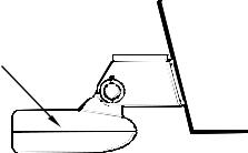
4.If the transducer is mounted on the transom, make sure it doesn't interfere with the trailer or hauling of the boat. Also, don't mount it closer than approximately one foot from the engine's lower unit. This will prevent cavitation (bubble) interference with propeller operation.
5.If possible, route the transducer cable away from other wiring on the boat. Electrical noise from engine wiring, bilge pumps and aerators can be displayed on the sonar's screen. Use caution when routing the transducer cable around these wires.
CAUTION: Clamp the transducer cable to transom near the transducer. This will help prevent the transducer from entering the boat if it is knocked off at high speed.
Good location
|
Poor location |
Good |
|
location |
Good location |
Poor angle |
Good and poor transducer locations.
How low should you go?
For most situations, you should install your Skimmer transducer so that its centerline is level with the bottom of the boat hull. This will usually give you the best combination of smooth water flow and protection from bangs and bumps.
9
Transom
Transducer centerline
Hull bottom
Align transducer centerline with hull bottom.
However, there are times when you may need to adjust the transducer slightly higher or lower. (The slots in the mounting brackets allow you to loosen the screws and slide the transducer up or down.) If you frequently lose bottom signal lock while running at high speed, the transducer may be coming out of the water as you cross waves or wakes. Move the transducer a little lower to help prevent this.
If you cruise or fish around lots of structure and cover, your transducer may be frequently kicking up from object strikes. If you wish, you may move the transducer a little higher for more protection.
There are two extremes you should avoid. Never let the edge of the mounting bracket extend below the bottom of the hull. Never let the bottom – the face – of the transducer rise above the bottom of the hull.
Shoot-thru-hull vs. Transom Mounting
In a shoot-thru-hull installation, the transducer is bonded to the inside of the hull with epoxy. The sonar "ping" signal actually passes through the hull and into the water. This differs from a bolt-thru-hull installation (often called simply "thru-hull"). In that case, a hole is cut in the hull and a specially designed transducer is mounted through the hull with a threaded shaft and nut. This puts the transducer in direct contact with the water.
Typically, shoot-thru-hull installations give excellent high speed operation and good to excellent depth capability. There is no possibility of transducer damage from floating objects, as there is with a transommounted transducer. A transducer mounted inside the hull can't be knocked off when docking or loading on a trailer.
However, the shoot-thru-hull installation does have its drawbacks. First, some loss of sensitivity does occur, even on the best hulls. This varies from hull to hull, even from different installations on the same hull. This is caused by differences in hull lay-up and construction.
10
Second, the transducer angle cannot be adjusted for the best fish arches on your sonar display. (This is not an issue for flasher-style sonars.) Lack of angle adjustment can be particularly troublesome on hulls that sit with the bow high when at rest or at slow trolling speeds.
Third, a transducer CAN NOT shoot through wood and metal hulls. Those hulls require either a transom mount or a thru-hull installation.
Fourth, if your Skimmer transducer has a built in temp sensor, it will only show the temperature of the bilge, not the water surface temp.
Follow the testing procedures listed in the shoot-thru-hull installation section at the end of this lesson to determine if you can satisfactorily shoot through the hull.
TRANSOM TRANSDUCER ASSEMBLY AND MOUNTING
The best way to install the transducer is to loosely assemble all of the parts first, place the transducer's bracket against the transom and see if you can move the transducer so that it's parallel with the ground.
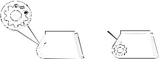
1.Assembling the bracket. Press the two small plastic ratchets into the sides of the metal bracket as shown in the following illustration. Notice there are letters molded into each ratchet. Place each ratchet into the bracket with the letter "A" aligned with the dot stamped into the metal bracket. This position sets the transducer's coarse angle adjustment for a 14° transom. Most outboard and stern-drive transoms have a 14° angle.
Dot
Align plastic ratchets in bracket.
2. Aligning the transducer on the transom. Slide the transducer between the two ratchets. Temporarily slide the bolt though the transducer assembly and hold it against the transom. Looking at the transducer from the side, check to see if it will adjust so that its face is parallel to the ground. If it does, then the "A" position is correct for your hull.
If the transducer's face isn't parallel with the ground, remove the transducer and ratchets from the bracket. Place the ratchets into the holes in the bracket with the letter "B" aligned with the dot stamped in the bracket.
11
Reassemble the transducer and bracket and place them against the transom. Again, check to see if you can move the transducer so it's parallel with the ground. If you can, then go to step 3. If it doesn't, repeat step 2, but use a different alignment letter until you can place the transducer on the transom correctly.
Ratchets
Insert bolt and check transducer position on transom.
3.Assembling the transducer. Once you determine the correct position for the ratchets, assemble the transducer as shown in the follow-
ing figure. Don't tighten the lock nut at this time.
Metal Nut washer
Rubber |
Metal washer |
washers |
|
|
Bolt |
Assemble transducer and bracket.
4.Drilling mounting holes. Hold the transducer and bracket assembly against the transom. The transducer should be roughly parallel to the ground. The transducer's centerline should be in line with the bottom of the hull. Don't let the bracket extend below the hull!
Mark the center of each slot for the mounting screw pilot holes. You will drill one hole in the center of each slot. Drill the holes using the #29 bit (for the #10 screws).
12

Transom
Transom
Position transducer mount on transom and mark mounting holes. Side view shown at left and seen from above at right.
5. Attaching transducer to transom. Remove the transducer from the bracket and re-assemble it with the cable passing through the bracket over the bolt as shown in the following figures.
Route cable over bolt and through bracket. Side view shown at left and seen from above at right.
Attach the transducer to the transom. Slide the transducer up or down until it's aligned properly with the bottom of the hull as shown in the preceding and following figures. Tighten the bracket's mounting screws, sealing them with the sealant/adhesive compound.
Adjust the transducer so that it's parallel to the ground and tighten the nut until it touches the outer washer, then add 1/4 turn. Don't over tighten the lock nut! If you do, the transducer won't "kick-up" if it strikes an object in the water.
Bottom of hull
Flat-bottom hull |
Deep-"vee" hull |
Align transducer centerline with hull bottom and attach to transom.
13
6. Route the transducer cable through or over the transom to the sonar unit. Make sure to leave some slack in the cable at the transducer. If possible, route the transducer cable away from other wiring on the boat. Electrical noise from the engine's wiring, bilge pumps, VHF radio wires and cables, and aerators can be picked up by the sonar. Use caution when routing the transducer cable around these wires.
WARNING:
Clamp the transducer cable to the transom close to the transducer. This can prevent the transducer from entering the boat if it is knocked off at high speed.
If you need to drill a hole in the transom to pass the connector through, the required hole size is 5/8".
Caution:
If you drill a hole in the transom for the cable, make sure it is located above the waterline. After installation, be sure to seal the hole with the same marine grade aboveor below-waterline sealant/adhesive used for the mounting screws.
7. Make a test run to determine the results. If the bottom is lost at high speed, or if noise appears on the display, try sliding the transducer bracket down. This puts the transducer deeper into the water, hopefully below the turbulence causing the noise. Don't allow the transducer bracket to go below the bottom of the hull!
TROLLING MOTOR BRACKET INSTALLATION
1.Attach the optional TMB-S bracket to the transducer as shown in the following figure, using the hardware supplied with the transducer. (Note: The internal tooth washer is supplied with the TMB-S.)
Bolt |
Internal tooth washer |
TMB-S bracket |
|
|
 Nut
Nut 
 Flat washer
Attach motor mounting bracket to transducer.
2.Slide the adjustable strap supplied with the TMB-S through the slot in the transducer bracket and wrap it around the trolling motor. Position the transducer to aim straight down when the motor is in the water. Tighten the strap securely.
14
3. Route the transducer cable alongside the trolling motor shaft. Use plastic ties (not included) to attach the transducer cable to the trolling motor shaft. Make sure there is enough slack in the cable for the motor to turn freely. Route the cable to the sonar unit and the transducer is ready for use.
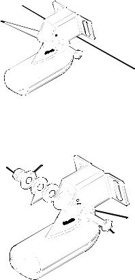
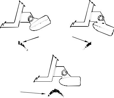
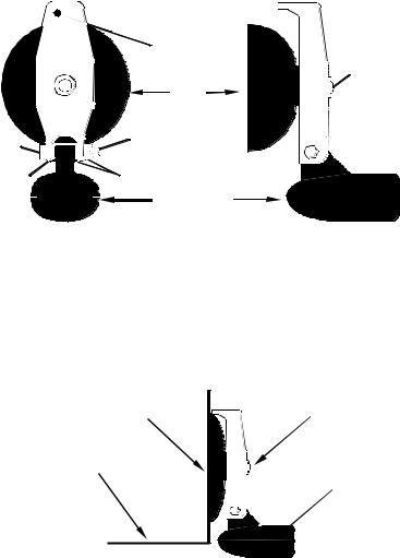
TRANSDUCER ORIENTATION AND FISH ARCHES
If you do not get good fish arches on your display, it could be because the transducer is not parallel with the ground when the boat is at rest in the water or at slow trolling speeds.
|
Partial fish arches |
Transducer aimed |
Transducer aimed |
too far back |
too far forward |
Full fish arch
Proper transducer angle
Transducer angles and their effects on fish arches.
If the arch slopes up – but not back down – then the front of the transducer is too high and needs to be lowered. If only the back half of the arch is printed, then the nose of the transducer is angled too far down and needs to be raised.
NOTE:
Periodically wash the transducer's face with soap and water to remove any oil film. Oil and dirt on the face will reduce the sensitivity or may even prevent operation.
15
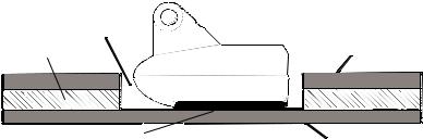
SHOOT-THRU-HULL PREPARATION Hulls With Floatation Materials
The transducer installation inside a fiberglass hull must be in an area that does not have air bubbles in the resin or separated fiberglass layers. The sonar signal must pass through solid fiberglass. A successful transducer installation can be made on hulls with flotation materials (such as plywood, balsa wood or foam) between layers of fiberglass if the material is removed from the chosen area. See the figure below.
WARNING:
Do not remove any material from your inner hull unless you know the hull's composition. Careless grinding or cutting on your hull can result in damage that could sink your boat. Contact your boat dealer or manufacturer to confirm your hull specifications.
Fill with epoxy
Flotation material |
Inner hull |
Epoxy to hull first |
Outer hull |
Epoxy the transducer to a solid portion of the hull.
For example, some (but not all) manufacturers use a layer of fiberglass, then a core of balsa wood, finishing with an outer layer of fiberglass. Removing the inner layer of fiberglass and the balsa wood core exposes the outer layer of fiberglass. The transducer can then be epoxied directly to the outer layer of fiberglass. After the epoxy cures for 24 hours, fill the remaining space with polyester resin. When the job is finished, the hull is watertight and structurally sound. Remember, the sonar signal must pass through solid fiberglass. Any air bubbles in the fiberglass or the epoxy will reduce or eliminate the sonar signals.
Testing Determines Best Location
Ideally, the shoot-thru transducer should be installed as close to the transom as possible, close to the centerline. This will give you the best performance during high speed maneuvers.
16
Transducer location |
Transducer location |
(high speed) |
(trolling speed) |
Shoot-thru-hull transducer locations for high speed or trolling speed operation.
To choose the proper location for shoot-thru-hull mounting, follow these testing procedures: (You may need a helper to complete these steps.)
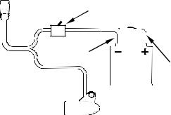
1.Anchor the boat in about 30 feet of water. Add a little water to the sump of the boat. Plug the transducer into the sonar unit, turn it on, then hold the transducer over the side of the boat in the water. Adjust the sensitivity and range controls until a second bottom echo is seen on the display. (You'll need to turn off Auto Sensitivity, Auto Depth Range and ASP™. Try a range setting that is two to three times the water depth. The harder (more rocky) the bottom, the easier it will be to get a second bottom signal.) Don't touch the controls once they've been set.
 True bottom
Second bottom
Manual range setting
Example of a second bottom signal. Unit is in 30 feet of water, with range set at 80 feet and sensitivity set at 87 percent.
2.Next, take the transducer out of the water and place it in the water in the sump of the boat, face down. (The transducer face is shown in the figure on the following page.) Notice how the signal strength decreases. The second bottom signal will probably disappear and the bottom signal intensity will likely decrease.
17
3. Now move the transducer around to find the best location with the strongest possible bottom signal. If you find a spot with an acceptable bottom signal, mark the location and move on to step 4.
If you can't get an acceptable bottom signal, try turning up the sensitivity by three or five keystrokes and then move the transducer around once more. If you find a spot that works, mark it and move on to step 4.
If you have to turn up sensitivity by more than five keystrokes to get a good signal, the transducer should be mounted on the outside of the hull. This is especially true if you have to turn sensitivity all the way up to get a decent bottom signal.
4.Most people can get good results by following steps 1 through 3, so this step is optional. If you want to make an extra effort to be absolutely sure that your selected location will work under all conditions, make a test run with the boat on plane and observe the bottom signal. You'll need to figure some way to prop the transducer into position while you make your test run. (A brick or two might be sufficient to hold it in place.)
5.When you're satisfied with a location, mark it and proceed with the installation.
Shoot-thru-hull Installation
If you are installing the transducer on a hull with floatation material sandwiched within the hull, refer to the text "Hulls With Flotation Materials."
1.Make sure the area is clean, dry and free of oil or grease, then sand both the inside surface of the hull and the face of the transducer with 100 grit sandpaper. The sanded hull area should be about 1-1/2 times the diameter of the transducer. The surface of the hull must be flat so the entire transducer face is in contact with the hull prior to bonding. After sanding, clean the hull and transducer with rubbing alcohol to remove any sanding debris.
WARNING:
Use only the epoxy available from LEI. It has been formulated to work with these installation procedures. Other epoxy types may be too thin or may not cure to the right consistency for optimum transducer performance.
18
2.The epoxy consists of the epoxy itself and a hardener. Remove the two compounds from the package and place them on the paper plate. Thoroughly stir the two compounds together until the mixture has a uniform color and consistency. Do not mix too fast or bubbles will form in the epoxy. After mixing, you have 20 minutes to complete the installation before the epoxy becomes unworkable.
Spread epoxy here
Sand this surface
Epoxy transducer to hull.
Spread a thin layer of epoxy (about 1/16" or 1.5 mm thick) on the face of the transducer as shown in the previous figure. Make sure there are no air pockets in the epoxy layer! Then, apply the remaining epoxy to the sanded area on the hull.
3.Press the transducer into the epoxy, twisting and turning it to force any air bubbles out from under the transducer face. Stop pressing when you bottom out on the hull. When you're finished, the face of the transducer should be parallel with the hull, with a minimum amount of epoxy between the hull and transducer.
4.Apply a weight, such as a brick, to hold the transducer in place while the epoxy cures. Be careful not to bump the transducer while the epoxy is wet. Leave the weight in place for a minimum of three hours. Allow the epoxy to cure for 24 hours before moving the boat.
5.After the epoxy has cured, route the cable to the sonar unit and it's ready to use.
POWER AND CABLE CONNECTIONS
The unit works from a 12-volt battery system. For the best results, attach the power cable directly to the battery. You can attach the power cable to an accessory or power buss, however you may have problems
19
with electrical interference. Therefore, it's safer to go ahead and attach the power cable directly to the battery.
CAUTION:
When using the unit in a saltwater environment, we strongly recommend that you shut off the power supply to the power cable when the unit is not in use. When the unit is turned off but still connected to a power supply, electrolysis can occur in the power cable plug. This may result in corrosion of the plug body along with the electrical contacts in the cable and the unit's power socket.
In saltwater environments we recommend you connect the power cable to the auxiliary power switch included in most boat designs. If that results in electrical interference, or if such a switch is not available, we recommend connecting direct to the battery and installing an inline switch. This will let you shut off power to the power cable when the unit is not in use. When you are not using the unit, you should always shut off power to the power cable, especially when the power cable is disconnected from the unit.
To unit |
Optional power off switch |
||
for saltwater installations |
|||
|
|||
|
Black wire |
|
|
|
12 volt |
Red wire with |
|
|
3 amp fuse |
||
|
battery |
||
|
|
||
Power and transducer connections for the M52 Pro sonar units (direct battery connection shown).
If possible, keep the power cable away from other boat wiring, especially the engine's wires. This will provide the best isolation from electrical noise. If the cable is not long enough, splice #18 gauge wire onto it. The power cable has two wires, red and black. Red is the positive lead, black is negative or ground. Make sure to attach the in-line fuse holder to the red lead as close to the power source as possible.
For example, if you have to extend the power cable to the battery or power buss, attach one end of the fuse holder directly to the battery or power buss. This will protect both the unit and the power cable in the event of a short. It uses a 3-amp fuse.
20
WARNING:
This product must be independently fused with the enclosed 3-amp fuse (or equivalent), even if you connect to a fused accessory or power buss.
If a malfunction happens inside the unit, extensive damage can occur if the enclosed fuse is not used. As with all electrical devices, this unit could be damaged to a point that it is unrepairable and could even cause harm to the user when not properly fused.
CAUTION:
Failure to use the enclosed 3-amp fuse will void your warranty! For a replacement, use a type 3AG 3-amp fuse.
This unit has reverse polarity protection. No damage will occur if the power wires are reversed. However, the unit will not work until the wires are attached correctly.
MOUNTING THE SONAR UNIT: In-Dash or Bracket
You can install the sonar unit on the top of a dash with the supplied bracket. It can also be installed in the dash with an optional FM-6 dash-mounting kit.
In-Dash Installation
The following figure shows the approximate shape for in-dash mounting an M52 Pro. The in-dash adapter kit includes a template for cutting the mounting hole and complete installation instructions on instruction sheet 988-0147-631.
21

Top
ALWAYS VERIFY DIMENSIONS.
Cut along this line
In-dash mounting template for M52 Pro.
NOTE: This figure is not printed to scale.
Bracket Installation
Mount the unit in any convenient location, provided there is clearance when it’s tilted for the best viewing angle. You should also make sure there is enough room behind the unit to attach the power/transducer cable. (See the following drawings, which show the dimensions of a mounted M52 Pro sonar unit.)
Holes in the bracket’s base allow wood screw or through-bolt mounting. You may need to place a piece of plywood on the back side of thin panels to reinforce the panel and secure the mounting hardware.
Drill a 5/8" (15.9 mm) hole in the dash for the power/transducer cable. The best location for this hole is immediately under the mounting bracket location. This way, the bracket can be installed so that it covers the hole, holds the cable in position and results in a neat installation. Some customers, however, prefer to mount the bracket to the side of the cable hole — it's a matter of personal preference. After drilling the hole, pass the connector up through the hole from under the dash.
22
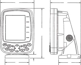
107.5 |
|
|
82.7 |
||
[4.23] |
|
[3.26] |
|
|
|
156
[6.26]
|
12.09 [0.48] |
|
|
|
|
76.9 |
Millimeter |
70.3 |
[3.03] |
[Inch] |
[2.77] |
Front view (left) and side view (right) showing dimensions of the M52 Pro when mounted on quick release bracket.
If you wish, you can fill in the hole around the cable with a good marine sealant compound. (Some marine dealers stock cable hole covers to conceal the opening.)
This unit uses a quick release mounting bracket. When you run the cable through the hole, make sure you allow enough slack for tilting the unit and attaching the connector. (The snug fit of the push-on waterproof connector requires some force to attach.) Also be sure there is enough cable slack for rotation if you decide to use the optional GBSA-3 swivel base. The swivel base lets you to rotate the sonar so it can be seen from different parts of the boat.
Align the bracket over the cable hole with the cable slots facing away from you and fit the cable through one of the slots. Fasten the bracket to the dash using the three screw holes.
23
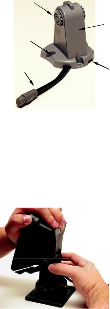
Ratchet |
|
|
Rear |
|
(away from viewer) |
Screw hole |
|
Power/transducer cable |
Cable slot |
M52 Pro quick release mounting bracket. Slots in the base allow routing the cable from beneath the mount.
Attach the unit to the bracket by first connecting the power/transducer cable. Then, hold the sonar unit vertically and slide it onto the bracket from above. (The back of the unit should be touching the front of the bracket as you lower it into position.) As you push down, the unit will lock into place with a distinct click.
To adjust the viewing angle, pinch the ratchets with one hand, then tilt the unit with your other hand. Release the ratchets and the unit locks into the new position. To dismount the unit for storage, press the ratchets and lift the unit off the bracket.
Depress  ratchets to
release. Swivel base
Adjust viewing angle: use one hand to press and release the springloaded ratchets while you move the unit with the other hand. An optional GBSA-3 swivel base is shown with the quick release bracket.
24
Portable Sonar Installation
Like many Lowrance products, the M52 Pro sonar is capable of portable operation. It uses the optional PPP-12 portable power pack.
The power pack and portable transducers expand the uses for your sonar. An alternative to the PPP-12 is the PPP-15 portable power pack, which was designed especially for ice fishing. It includes a rechargeable gel cell battery and a transducer designed for stationary use.
The PPP-12 package includes the power pack, battery adapter and a portable transducer. The transducer can be stored inside the power pack. The PPP-12 requires eight AA alkaline batteries. Batteries are not included.
Installing the Batteries
Release the latch on the front of the power pack case. Open the compartment and install eight AA batteries into the adapter. For the longest life, we recommend you use alkaline batteries.
After installing the batteries, plug the cable's power connector into the socket on the battery compartment cover. Route the cable's unit connector and about 6 inches of cable through the opening under the sonar mount. Close the cover, plug the connector into the sonar unit and mount the unit on the built-in bracket.
In cold weather the efficiency of dry cell batteries drops with the temperature. We find it a good idea to have the sonar unit good and warm along with the batteries before we leave home.
WARNING:
Never heat the batteries over an open flame or direct hot air onto them. A fire or explosion could result.
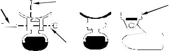
Portable Transducer Assembly
Recommended tools for installation include a slotted screw driver and two adjustable wrenches.
Assemble the transducer and bracket as shown in the following figure. Attach the transducer to the bracket with the supplied hardware.
Make sure there is one washer on each side of the transducer, inside the bracket. Slide the other washer over the end of the bolt and thread the nut onto it.
Screw the suction cup onto the bracket using the supplied screw and flat washer. Tie the nylon cord through the hole in the top of the bracket. When using this transducer, tie the other end of the nylon cord to the boat. This will help prevent the loss of the transducer if it comes off the boat.
25
Tie nylon cord here
|
Suction |
Screw |
|
cup |
|
Bolt |
Nut |
|
|
|
|
Washer |
Washer |
|
|
|
|
|
Transducer |
|
Portable transducer assembly: rear view (left) and side view (right.)
Clean the chosen area of the hull before attaching the suction cup. Locate the transducer on the hull as shown in the following figure. Don't allow the bracket to extend below the hull, because water pressure against it can cause the suction cup to come off at speed.
Moisten the cup, then press it onto the hull as firmly as possible. Tie the nylon cord to the boat and route the transducer cable to the sonar unit. Your portable sonar is now ready for use.
Suction |
Bracket |
cup |
Hull
Transducer
Portable transducer installed on boat transom.
NOTE:
For optimum operation, the portable transducer should be adjusted so that it is parallel to the ground. For more information on this, see the earlier segment on Transducer Orientation and Fish Arches.
26
Section 3:
Basic Sonar Operation
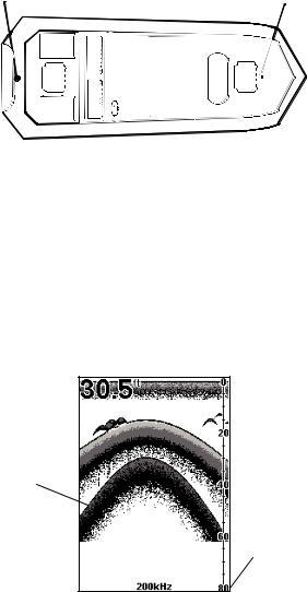
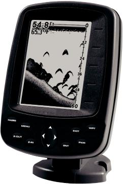
Keyboard
Numbers in the photo correspond to key explanations below.
2
3 |
6 |
7 |
|
8 4
9 |
1 |
|
5 |
||
|
Lowrance M52 Pro Sonar.
1.PWR/LIGHT – The PWR key turns the unit on and off and activates the backlight. Depress the PWR key for 3 seconds to turn off the unit.
2.PAGES – Pressing this and the arrow keys (4) switches the unit between the different page display screens.
3.MENU – Press this key to show the menus and submenus, which allow you to select a command or adjust a feature. This also accesses search functions for streets, intersections, addresses and highway exits.
4.ARROW KEYS – These keys are used to navigate through the menus, make menu selections, move the plotter cursor and sonar chart cursor and enter data.
27
5.ENT – This key allows you to save data, accept values or execute menu commands. It is also used to create event marker icons.
6.EXIT – The Exit key lets you return to the previous screen, clear data or close a menu.
7.WPT – The Waypoint key is used to save and recall waypoints, search for waypoints and access the waypoint list. It's also involved in some navigation functions.
8.ZOUT – This key lets you zoom the screen out. On the Sonar Page, this key returns you to a full sonar chart display, showing the entire water column from surface to bottom. On the Plotter Page, this lets you see a larger geographic area on the display. Less detail is seen as you zoom out.
9.ZIN – This key lets you zoom the screen in. On the Sonar Page, this key enlarges fish signals and bottom detail. On the Plotter Page, zooming in lets you see greater detail in a smaller geographic area on the display.
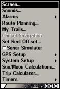
Main Menu
Access the Main Menu by pressing MENU|MENU. Select a menu item by using ↑ or ↓ to highlight the command and pressing ENT. To clear the Main Menu screen and return to the Page display, press EXIT.
Main Menu Commands
•Screen:(CONTRAST, BRIGHTNESS and DISPLAY MODE):
change the appearance of the display screen. Use these commands to adjust how the screen looks under various lighting conditions.
•Sounds: controls sound levels for keystrokes and alarms.
•Alarms: turns alarms on or off and changes alarm thresholds.
NOTE:
Route Planning, My Trails, GPS Setup and Trip Calculator will be addressed in the GPS section.
•Set Keel Offset: calibrates the unit to show depth under the keel or actual depth from the surface.
•Sonar Simulator: turns the unit's simulator feature on and off.
•System Setup: provides access to general configuration options, like Units of Measure, Reset Options, Pop-up Help, Set Language, etc.
28
 Loading...