

Lowrance HDS Live Installation Manual
ENGLISH
HDS Live
Installation Manual
www.lowrance.com


Preface
Disclaimer
As Navico is continuously improving this product, we retain the
right to make changes to the product at any time which may not be
reflected in this version of the manual. Please contact your nearest
distributor if you require any further assistance.
It is the owner’s sole responsibility to install and use the equipment
in a manner that will not cause accidents, personal injury or
property damage. The user of this product is solely responsible for
observing maritime safety practices.
NAVICO HOLDING AS AND ITS SUBSIDIARIES, BRANCHES AND
AFFILIATES DISCLAIM ALL LIABILITY FOR ANY USE OF THIS PRODUCT
IN A WAY THAT MAY CAUSE ACCIDENTS, DAMAGE OR THAT MAY
VIOLATE THE LAW.
This manual represents the product as at the time of printing.
Navico Holding AS and its subsidiaries, branches and affiliates
reserve the right to make changes to specifications without notice.
Governing language
This statement, any instruction manuals, user guides and other
information relating to the product (Documentation) may be
translated to, or has been translated from, another language
(Translation). In the event of any conflict between any Translation of
the Documentation, the English language version of the
Documentation will be the official version of the Documentation.
Copyright
Copyright © 2018 Navico Holding AS.
Warranty
The warranty card is supplied as a separate document. In case of any
queries, refer to the brand website of your unit or system:
www.lowrance.com
Preface | HDS Live Installation Manual
3

Compliance statements
Europe
Navico declare under our sole responsibility that the product
conforms with the requirements of:
• CE under RED 2014/53/EU
The relevant declaration of conformity is available in the product's
section at the following website:
• www.lowrance.com
Countries of intended use in the EU
AT - Austria
BE - Belgium
BG - Bulgaria
CY - Cyprus
CZ - Czech Republic
DK - Denmark
EE - Estonia
FI - Finland
FR - France
DE - Germany
GR - Greece
HU - Hungary
IS - Iceland
IE - Ireland
IT - Italy
LV - Latvia
LI - Liechtenstein
LT - Lithuania
LU - Luxembourg
MT - Malta
NL - Netherlands
NO - Norway
PL - Poland
PT - Portugal
RO - Romania
SK - Slovak Republic
SI - Slovenia
ES - Spain
SE - Sweden
CH - Switzerland
TR - Turkey
UK - United Kingdom
United States of America
Navico declare under our sole responsibility that the product
conforms with the requirements of:
• Part 15 of the FCC Rules. Operation is subject to the following
two conditions: (1) this device may not cause harmful
interference, and (2) this device must accept any interference
received, including interference that may cause undesired
operation
4
Preface | HDS Live Installation Manual

Warning: The user is cautioned that any changes or
modifications not expressly approved by the party
responsible for compliance could void the user’s
authority to operate the equipment.
Ú
Note: This equipment generates, uses and can radiate radio
frequency energy and, if not installed and used in accordance
with the instructions, may cause harmful interference to radio
communications. However, there is no guarantee that the
interference will not occur in a particular installation. If this
equipment does cause harmful interference to radio or
television reception, which can be determined by turning the
equipment off and on, the user is encouraged to try to correct
the interference by one or more of the following measures:
• Reorient or relocate the receiving antenna
• Increase the separation between the equipment and receiver
• Connect the equipment into an outlet on a circuit different from
that of the receiver is connected
• Consult the dealer or an experienced technician for help
Industry Canada
This device complies with Industry Canada’s license-exempt RSSs.
Operation is subject to the following two conditions: (1) This device
may not cause interference; and (2) This device must accept any
interference, including interference that may cause undesired
operation of the device.
Le présent appareil est conforme aux CNR d’Industrie Canada
applicables aux appareils radio exempts de licence. L’exploitation
est autorisée aux deux conditions suivantes: (1) l’appareil ne doit pas
produire de brouillage, et. (2) l’utilisateur de l’appareil doit accepter
tout brouillage radioélectrique subi, même si le brouillage est
susceptible d’en compromettre le fonctionnemen.
Industry Canada Statement: Under Industry Canada regulations, this
radio transmitter may only operate using an antenna of a type and
maximum (or lesser) gain approved for the transmitter by Industry
Canada. To reduce potential radio interference to other users, the
antenna type and its gain should be so chosen that the equivalent
isotropically radiated power (e.i.r.p.) is not more than that necessary
for successful communication.
Preface | HDS Live Installation Manual
5

Conformément à la réglementation d’Industrie Canada, le présent
émetteur radio peut fonctionner avec une antenne d’un type et
d’un gain maximal (ou inférieur) approuvé pour l’émetteur par
Industrie Canada. Dans le but de réduire les risques de brouillage
radioélectrique à l’intention des autres utilisateurs, il faut choisir le
type d’antenne et son gain de sorte que la puissance isotrope
rayonnée quivalente (p.i.r.e.) ne dépassepas l’intensité nécessaire à
l’établissement d’une communication satisfaisante.
Australia and New Zealand
Navico declare under our sole responsibility that the product
conforms with the requirements of:
• level 2 devices of the Radiocommunications (Electromagnetic
Compatibility) standard 2017
• radiocommunications (Short Range Devices) Standards 2014
Internet usage
Some features in this product use an internet connection to
perform data downloads and uploads. Internet usage via a
connected mobile/cell phone internet connection or a pay-per-MB
type internet connection may require large data usage. Your service
provider may charge you based on the amount of data you transfer.
If you are unsure, contact your service provider to confirm rates and
restrictions.
Trademarks
Navico® is a registered trademark of Navico Holding AS.
Lowrance® is a registered trademark of Navico Holding AS.
Bluetooth® is a registered trademark of Bluetooth SIG, Inc.
CZone™ is a trademark of Power Products LLC.
Evinrude® is a registered trademark of BRP US, Inc.
HDMI® and HDMI™, the HDMI Logo, and High-Definition Multimedia
Interface are trademarks or registered trademarks of HDMI Licensing
LLC in the United States and other countries.
Mercury® is a registered trademark of Mercury.
NMEA® and NMEA 2000® are registered trademarks of the National
Marine Electronics Association.
6
Preface | HDS Live Installation Manual

Power-Pole® is a registered trademark of JL Marine Systems, Inc.
SD™ and microSD™ are trademarks or registered trademarks of
SD-3C, LLC in the United States, other countries or both.
SmartCraft VesselView® is a registered trademark of Mercury.
Suzuki® is a registered trademark of Suzuki.
Yamaha® is a registered trademark of Yamaha.
About this manual
This manual is a reference guide for installing units.
Some features may not be activated or available for screenshots in
the manual. As a result, screenshots of menus and dialogs may not
match the look of your unit.
Important text that requires special attention from the reader is
emphasized as follows:
Ú
Note: Used to draw the reader’s attention to a comment or
some important information.
Warning: Used when it is necessary to warn
personnel that they should proceed carefully to
prevent risk of injury and/or damage to equipment/
personnel.
Preface | HDS Live Installation Manual
7

8
Preface | HDS Live Installation Manual

Contents
11 Introduction
11
Parts included
12 Keys
14 Card reader
15 Connectors
16 Installation
16 Installation guidelines
17 U-bracket mounting
17 Panel mounting
18 Wiring
18 Connectors
18 Wiring guidelines
19 Power, NMEA 0183 and video input
22 USB devices
23 NMEA 2000
25 Ethernet device connection
26 HDMI input
27 Sonar CH1 - blue 9-pin connector
27 Sonar CH2 - black 9-pin connector
28 Software setup
28 First time startup
28 Software setup sequence
28 Turning the system on and off
28 The settings dialog
29 System settings
30 Alarms
31 Radar settings
36 Sonar settings
40 Autopilot settings
45 Fuel settings
47 Wireless settings
48 Network settings
52 3rd party support
52 SmartCraft VesselView integration
Contents | HDS Live Installation Manual
9

52 Suzuki engine integration
52
Yamaha engine integration
53 Evinrude engine integration
53 Power-Pole anchors
53 C-Zone
56 Accessories
57 Supported data
57 NMEA 2000 compliant PGN List
61 NMEA 0183 supported sentences
63 Technical specifications
63 HDS Live
66 Dimensional drawings
66 7" unit
66 9" unit
67 12" unit
67 16" unit
10
Contents | HDS Live Installation Manual
Introduction
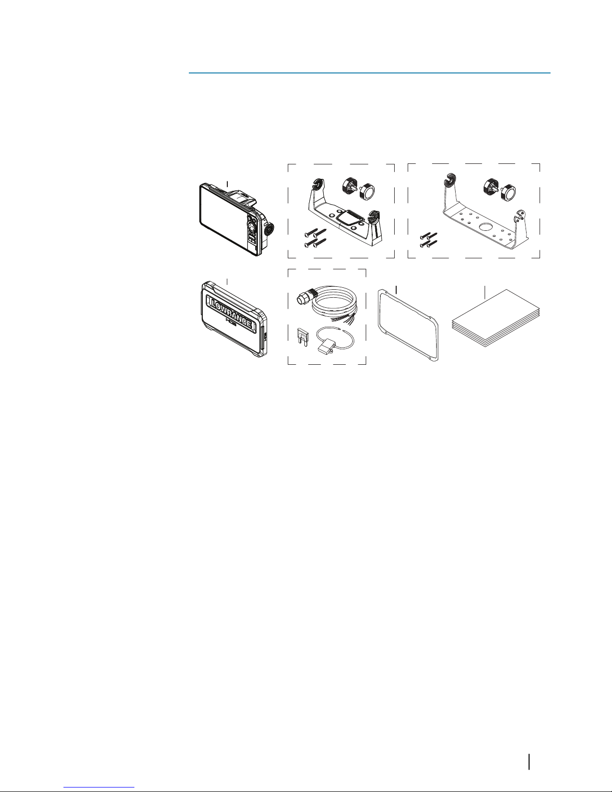
Parts included
HDS Live
C
A
D
B1
B2
F
E
A HDS Live unit
B1 U-bracket kit (plastic), HDS-7 Live and HDS-9 Live
B2 U-bracket kit (metal), HDS-12 Live and HDS-16 Live
C Sun cover
D Power cable kit
E Gasket
F Documentation pack
1
Introduction | HDS Live Installation Manual
11
Keys
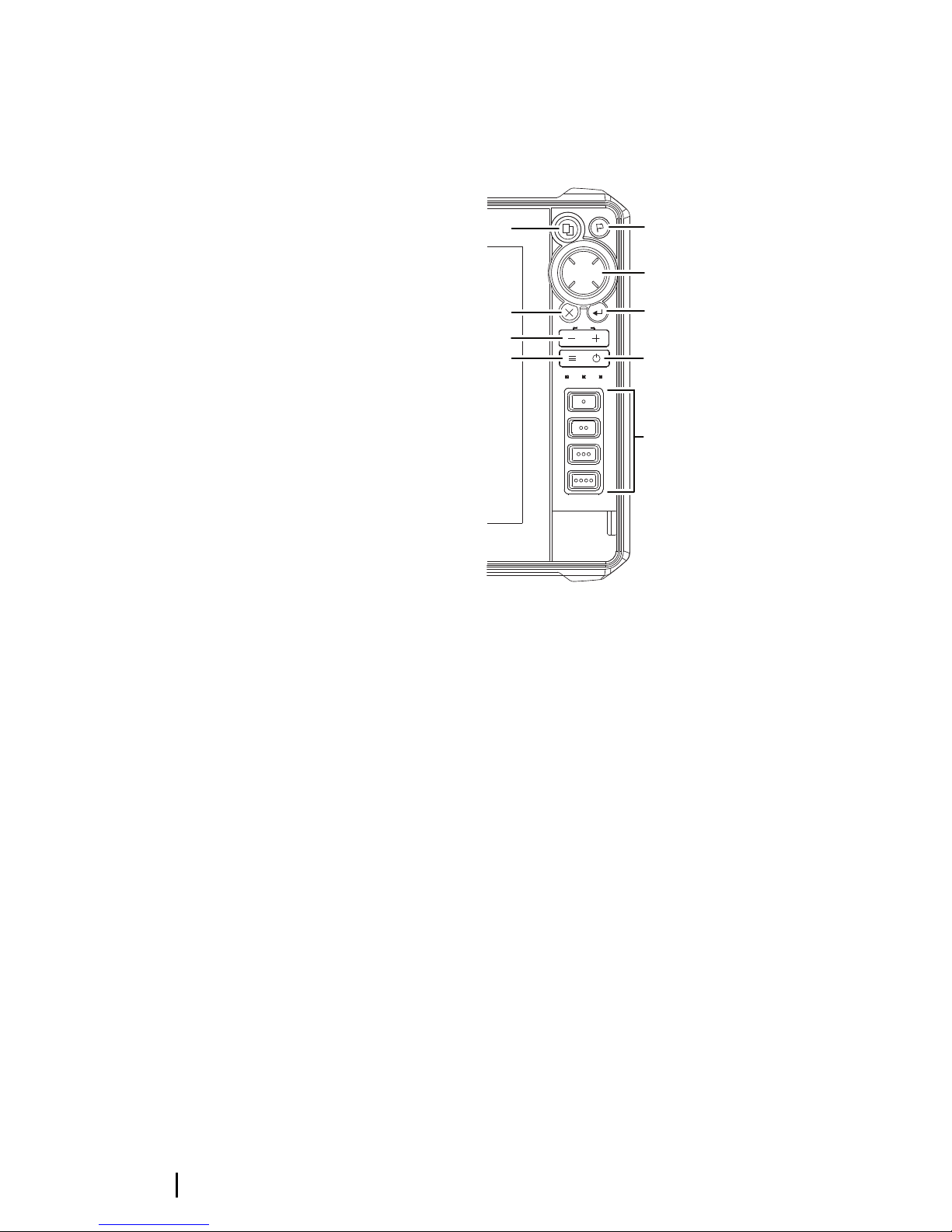
The front panel keys
MOB
B
C
E
H
I
A
D
F
G
A Pages key
• Press once to activate the Home page. Repeat short
presses to cycle the favorite buttons
• Press and hold is configurable. Refer to the operator
manual for details
B Waypoint key
• Press to open the new waypoint dialog
• Press twice to save a waypoint
• Press and hold to access the find dialog
C Arrow keys
• Press arrows to move through menu items, to adjust a
value, and to move the cursor on a panel
D Exit (X) key
• Press to exit a dialog, to return to previous menu level, to
remove the cursor from the panel or to restore the cursor
on the panel
12
Introduction | HDS Live Installation Manual

E Enter key
• Press to select or save your settings
F Zoom keys and MOB key
• Zoom keys for panels and images
• Simultaneous pressing both keys saves a Man Overboard
(MOB) waypoint at the current vessel position
G Menu key
• Press to display the menu for the active panel/overlay
• Press twice to display the settings dialog
• Press and hold to hide or show the menu
H Power key
• Press to turn the unit ON
• Press and hold to turn the unit OFF
• When ON, press once to display the System Controls
dialog. Repeat short presses to cycle the backlight
brightness
I Quick access keys (HDS-12 Live and HDS-16 Live units
only)
• For configuration of the quick access keys refer to the
operator manual.
Introduction | HDS Live Installation Manual
13
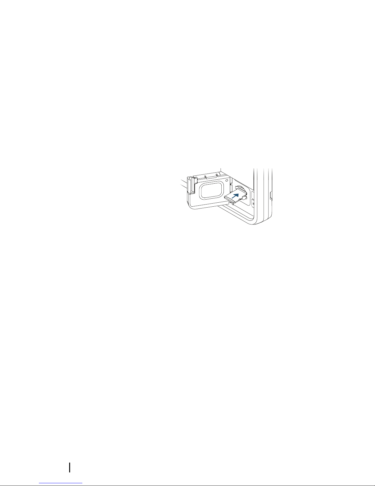
Card reader
A memory card can be used for:
• Chart data
• Software updates
• Transfer of user data
• System backup
Ú
Note: Do not download, transfer or copy files to a chart card.
Doing so can damage chart information on the chart card.
The protective door should always be securely shut immediately
after inserting or removing a card, in order to prevent possible water
ingress.
14
Introduction | HDS Live Installation Manual
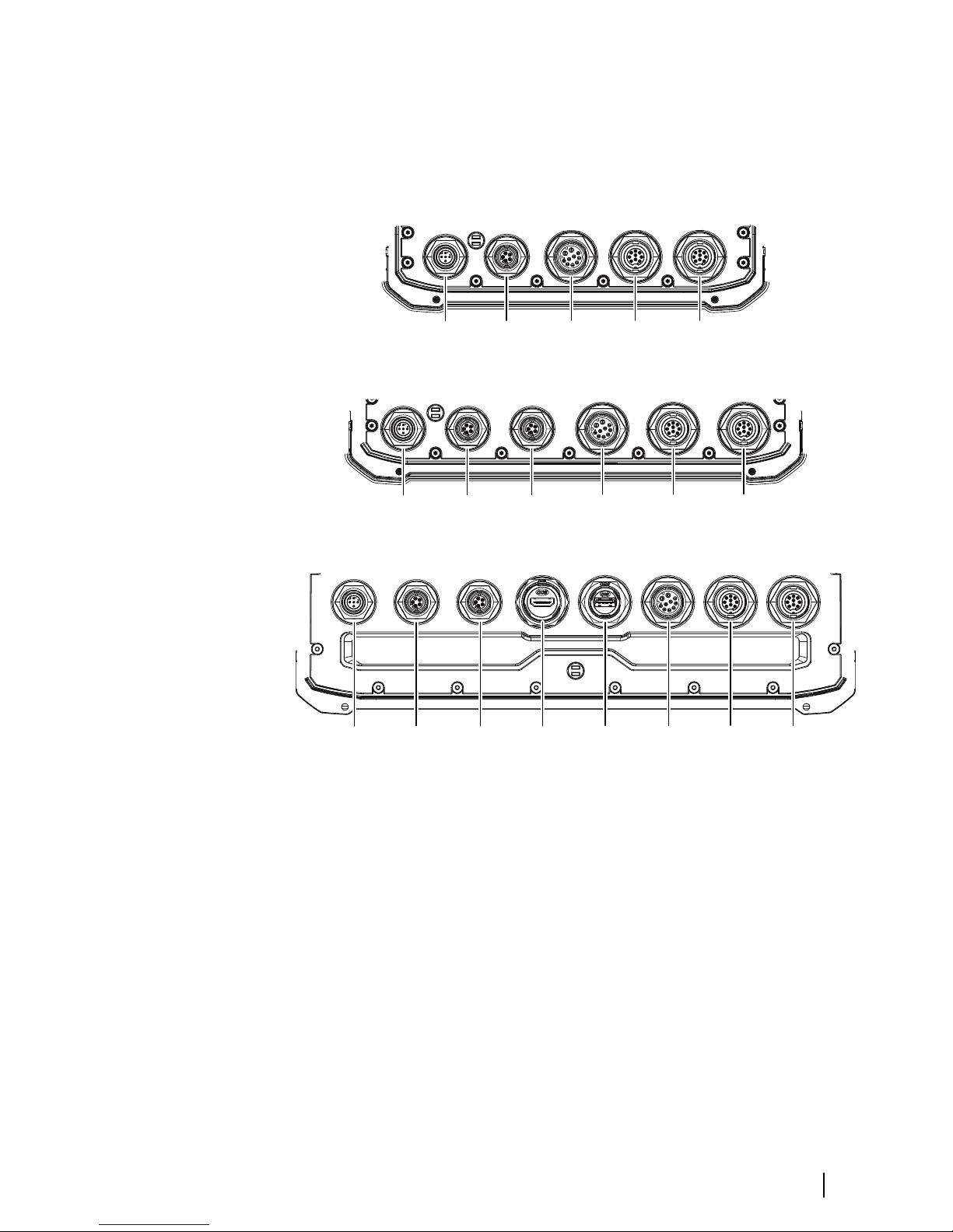
Connectors
HDS Live
7" unit
A B CDE
9" unit
A B CDE
D
12" and 16" unit
A B CDE
D
G
F
A Power, video input and NMEA 0183 connector
B Sonar CH1 - blue 9-pin connector
C Sonar CH2 - black 9-pin connector
D Ethernet connector (5-pin)
E NMEA 2000 connector
F HDMI output connector
G USB connector
Introduction | HDS Live Installation Manual
15

Installation
Installation guidelines
Choose the mounting location carefully, make sure that there are no
hidden electrical wires or other parts behind the panel before you
drill or cut. Ensure that any holes cut are in a safe position and will
not weaken the boat’s structure. If in doubt, consult a qualified boat
builder, or marine electronics installer.
Don´t:
• Mount any part where it can be used as a hand hold
• Mount any part where it might be submerged
• Mount any part where it will interfere with the operation,
launching, or retrieving of the boat
Do:
• Test the unit in its intended location to ensure satisfactory
wireless and GPS performance. Metal and carbon materials are
known to impact the performance in a negative way. A well
placed external GPS source and/or wireless module can be
added to overcome poor performance
• Consider the optimum viewing angles
• Consider the overall width and height requirements
• Consider access to the card reader
• Leave sufficient clearance to connect all relevant cables
• Check that it is possible to route cables to the intended
mounting location
Ú
Note: Where flush mounted, the enclosure should be dry and
well ventilated. In small enclosures, it may be required to fit
forced cooling.
Warning: Inadequate ventilation and subsequent
overheating of the unit may cause unreliable operation
and reduced service life. Exposing the unit to
conditions that exceeds the specifications could
invalidate your warranty. Refer to the technical
specifications in the "Technical specifications" on page 63.
2
16
Installation | HDS Live Installation Manual
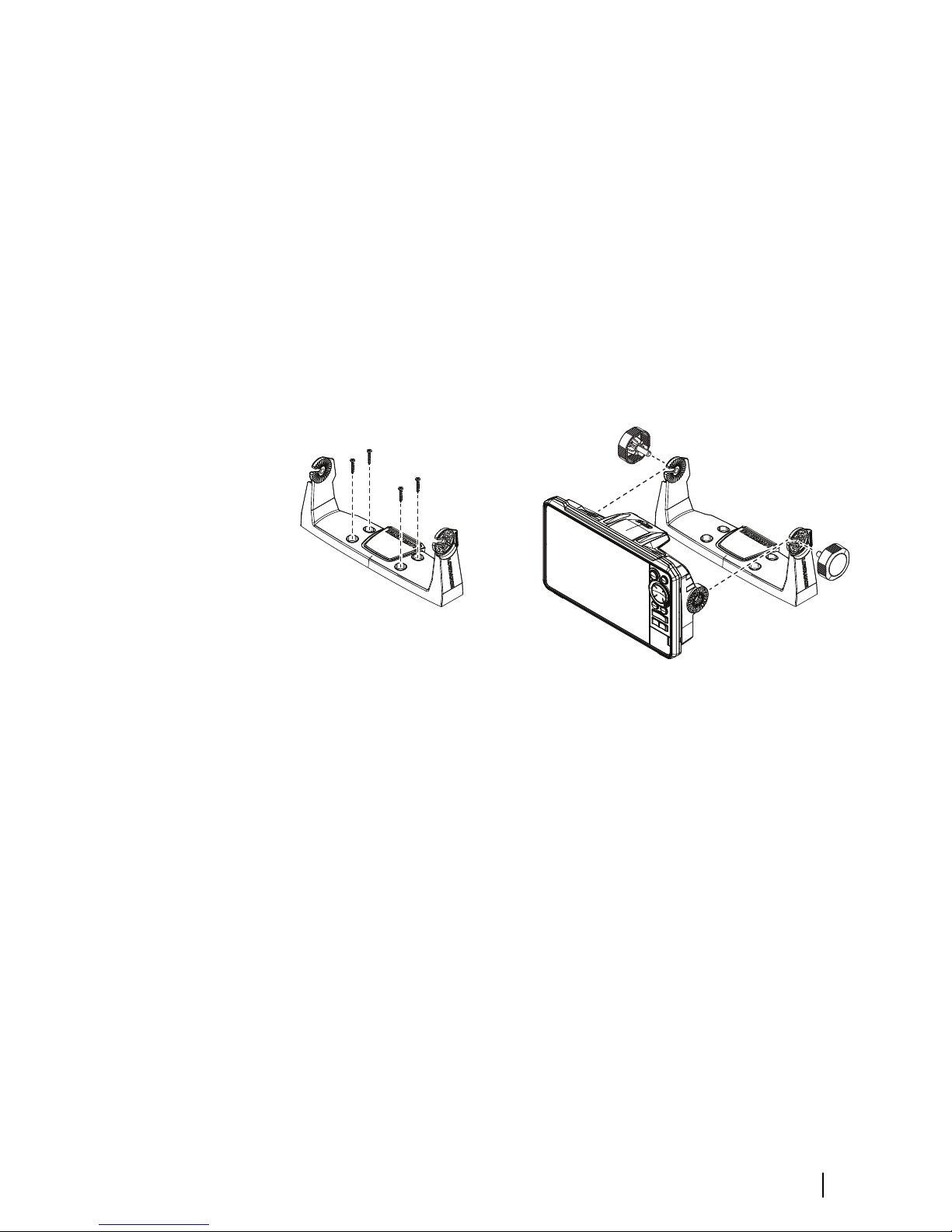
U-bracket mounting
1. Place the bracket in the desired mounting location. Ensure that
the chosen location has enough height to accommodate the
unit fitted in the bracket, and allows tilting of the unit. Also
adequate space is required on both sides to allow tightening
and loosening of the knobs.
2. Mark the screw locations using the bracket as a template, and
drill pilot holes. Use fasteners suited to the mounting surface
material.
3. Screw down the bracket.
4. Mount the unit to the bracket using the knobs. Hand tighten
only.
3
4
Panel mounting
Refer to the separate mounting template for panel mounting
instructions.
Installation | HDS Live Installation Manual
17
Wiring
Connectors
Different models have different connectors. For available
connectors and connector layout refer to "Connectors" on page 15.
Wiring guidelines
Don't:
• Make sharp bends in the cables
• Run cables in a way that allows water to flow down into the
connectors
• Run the data cables adjacent to radar, transmitter, or large/high
current carrying cables or high frequency signal cables.
• Run cables so they interfere with mechanical systems
• Run cables over sharp edges or burrs
Do:
• Make drip and service loops
• Use cable-tie on all cables to keep them secure
• Solder/crimp and insulate all wiring connections if extending or
shortening the cables. Extending cables should be done with
suitable crimp connectors or solder and heat shrink. Keep joins as
high as possible to minimize possibility of water immersion.
• Leave room adjacent to connectors to ease plugging and
unplugging of cables
Warning: Before starting the installation, be sure to
turn electrical power off. If power is left on or turned on
during the installation, fire, electrical shock, or other
serious injury may occur. Be sure that the voltage of the
power supply is compatible with the unit.
Warning: The positive supply wire (red) should
always be connected to (+) DC with a fuse or a circuit
breaker (closest available to fuse rating).
3
18
Wiring | HDS Live Installation Manual
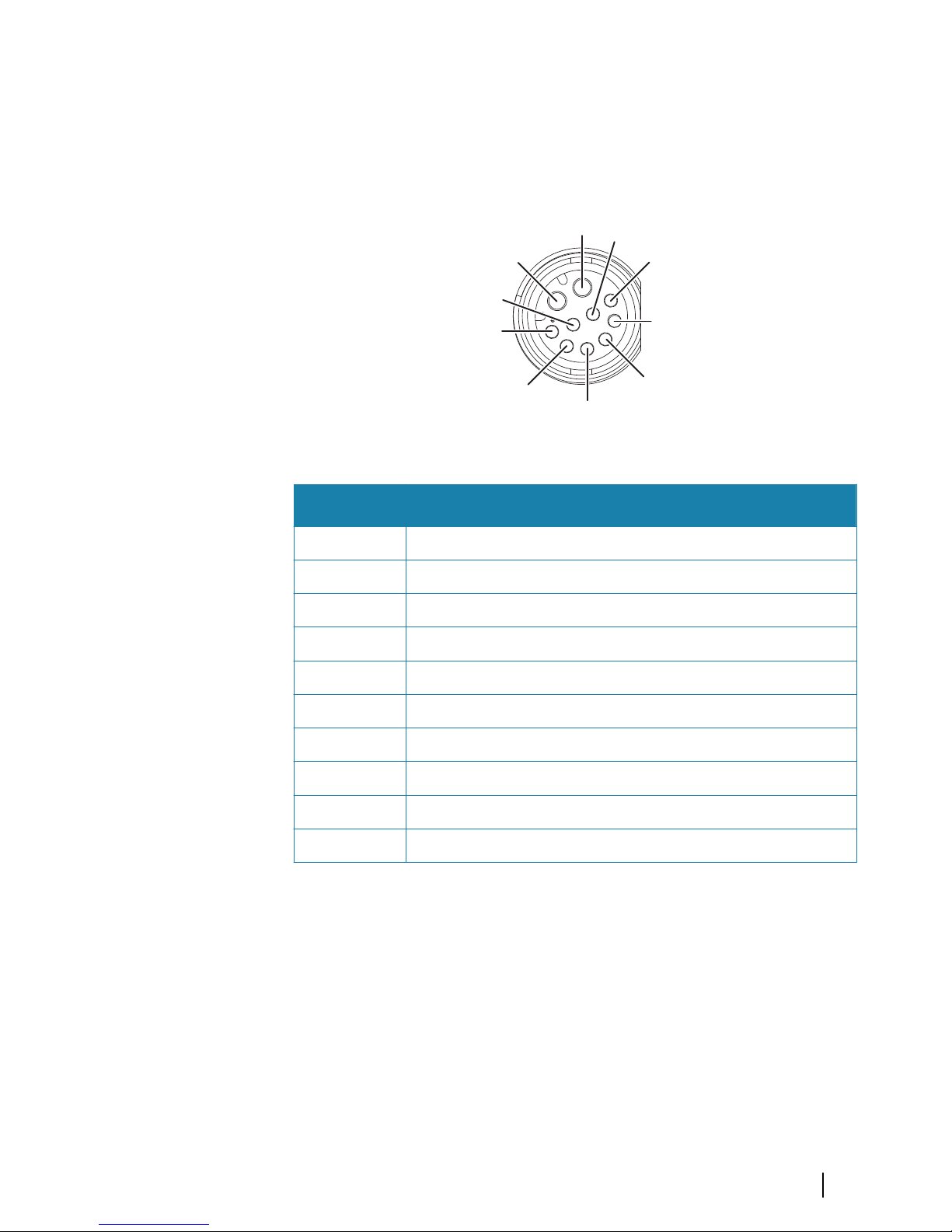
Power, NMEA 0183 and video input
Connector details
4
7
8 6
3
5
2
1
9
10
Unit socket (female)
Pin Purpose
1 Accessory wake up
2 Listener B (Rx_B)
3 Video in +
4 Talker B (Tx_B)
5 Drain
6 Talker A (Tx_A)
7 + 12 V DC
8 DC negative
9 Video in -
10 Listener A (Rx_A)
Ú
Note: To use the video input functionality, an adapter cable has
to be used (sold separately).
Power
The unit is designed to be powered by 12 V DC.
It is protected against reverse polarity, under voltage and over
voltage (for a limited duration).
Wiring | HDS Live Installation Manual
19

A fuse or circuit breaker should be fitted to the positive supply. For
recommended fuse rating, refer to "Technical specifications" on page 63.
NMEA 0183
The unit has a built in NMEA 0183 serial interface, providing both
input and output. The port(s) uses the NMEA 0183 (serial balanced)
standard, and can be configured in the software for different baud
rates up to 38,400 baud.
Talkers and listeners
Only one talker (output device) can be connected to a serial input
(RX) on the unit, in accordance with the NMEA0183 protocol.
However, an output port (TX) on the unit may be connected to up
to three listener (receiver) devices, dependent on the hardware
capabilities of the receiver.
Video input
The unit can be connected to a composite video source, and display
video images on its display.
Ú
Note: Camera cables are not supplied, and will need to be
selected to suit termination - RCA at the unit, and typically BNC
or RCA plug at the camera end.
Ú
Note: The video images will not be shared with another unit via
the network. It is only possible to view video on the unit
connected to the video source.
Ú
Note: Both NTSC and PAL formats are supported.
Video input configuration
Configurations to video input are made in the video panel, refer to
the Operator Manual for more information.
20
Wiring | HDS Live Installation Manual
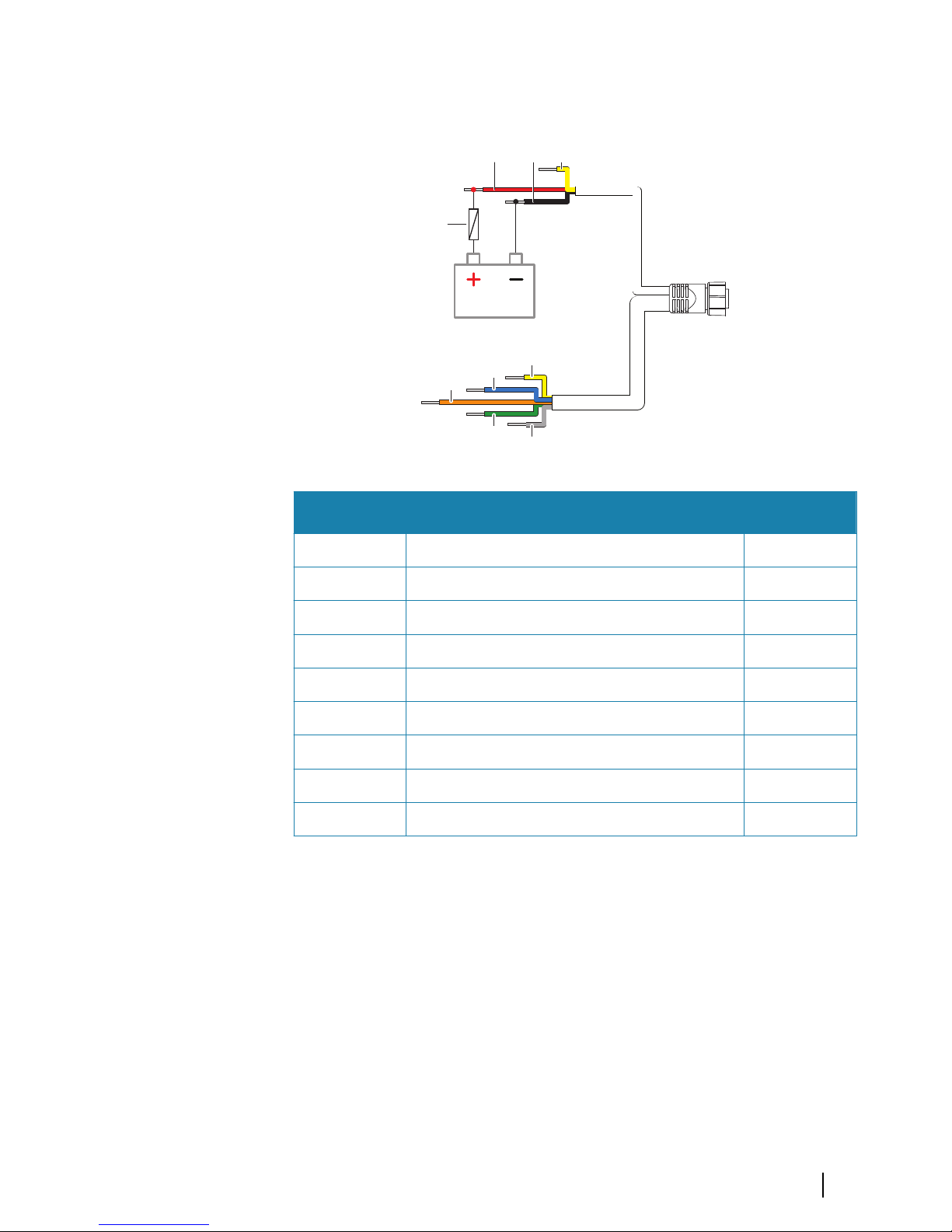
Power and NMEA 0183 cable
E
F
G
H
I
A B C D
Key Description Color
A + 12 V DC Red
B DC negative Black
C Fuse --
D Accessory wake up Yellow
E Talker A (Tx_A) Yellow
F Talker B (Tx_B) Blue
G Listener A (Rx_A) Orange
H Listener B (Rx_B) Green
I Ground (shield) --
Accessory wake up
The accessory wake up wire may be used to control the power state
of external equipment. Combine all accessory wake up wires on a
common bus or to a single termination point. When connected in
this manner, the connected equipment will turn on the moment
the unit is powered up.
Wiring | HDS Live Installation Manual
21
 Loading...