

Lowrance HDS-7, HDS-12, HDS-9, HDS-7 Gen3, HDS-9 Gen3 Installation Manual
...
ENGLISH
HDS Gen3
Installation Manual
lowrance.com


| 1
Preface
As Navico is continuously improving this product, we retain the
right to make changes to the product at any time which may
not be re ected in this version of the manual. Please contact
your nearest distributor if you require any further assistance.
It is the owner’s sole responsibility to install and use the
instrument and transducers in a manner that will not cause
accidents, personal injury or property damage. The user of
this product is solely responsible for observing safe boating
practices.
NAVICO HOLDING AS AND ITS SUBSIDIARIES, BRANCHES AND
AFFILIATES DISCLAIM ALL LIABILITY FOR ANY USE OF THIS
PRODUCT IN A WAY THAT MAY CAUSE ACCIDENTS, DAMAGE OR
THAT MAY VIOLATE THE LAW.
Governing Language: This statement, any instruction manuals,
user guides and other information relating to the product
(Documentation) may be translated to, or has been translated
from, another language (Translation). In the event of any
con ict between any Translation of the Documentation, the
English language version of the Documentation will be the
o cial version of the Documentation. This manual represents
the product as at the time of printing. Navico Holding AS and
its subsidiaries, branches and a liates reserve the right to make
changes to speci cations without notice.
Copyright
Copyright © 2014 Navico Holding AS.
Warranty
The warranty card is supplied as a separate document.
In case of any queries, refer to the brand web site of your
display or system:
www.lowrance.com
Declarations and conformance
This equipment is intended for use in international waters as
well as inland waters and coastal sea areas administered by
countries of the USA, E.U. and E.E.A.

2 |
Compliance Statements
Lowrance HDS-7, HDS-9, and HDS-12 Gen3:
• complies with CE under R&TTE directive 1999/5/
EC
• complies with the requirements of level 2 devices
of the Radio-communications (Electromagnetic
Compatibility) standard 2008
• This device complies with Part 15 of the FCC
Rules. Operation is subject to the following two
conditions: (1) this device may not cause harmful
interference, and (2) this device must accept any
interference received, including interference that
may cause undesired operation.
The relevant Declaration of Conformity is available on the
following website, under the model documentation section:
www.lowrance.com
Industry Canada
IC RSS-GEN, Sec 7.1.3 Warning Statement- (Required for licenseexempt devices)
This device complies with Industry Canada license-exempt
RSS standard(s). Operation is subject to the following two
conditions: (1) this device may not cause interference, and (2)
this device must accept any interference, including interference
that may cause undesired operation of the device.
Le présent appareil est conforme aux CNR d’Industrie
Canada applicables aux appareils radio exempts de licence.
L’exploitation est autorisée aux deux conditions suivantes : (1)
l’appareil ne doit pas produire de brouillage, et (2) l’utilisateur
de l’appareil doit accepter tout brouillage radioélectrique subi,
même si le brouillage est susceptible d’en compromettre le
fonctionnement.
Warning
The user is cautioned that any changes or modi cations not
expressly approved by the party responsible for compliance
could void the user’s authority to operate the equipment.
This equipment has been tested and found to comply
with the limits for a Class B digital device, pursuant to Part
15 of the FCC rules. These limits are designed to provide

| 3
reasonable protection against harmful interference in a
residential installation. This equipment generates, uses and
can radiate radio frequency energy and, if not installed and
used in accordance with the instructions, may cause harmful
interference to radio communications. However, there is no
guarantee that the interference will not occur in a particular
installation. If this equipment does cause harmful interference
to radio or television reception, which can be determined by
turning the equipment o and on, the user is encouraged to
try to correct the interference by one or more of the following
measures:
• Reorient or relocate the receiving antenna
• Increase the separation between the equipment and receiver
• Connect the equipment into an outlet on a circuit di erent
from that of the receiver
• Consult the dealer or an experienced technician for help

4 |
Countries of intended use in the EU:
AT - Austria
BE - Belgium
BG - Bulgaria
CY - Cyprus
CZ - Czech Republic DK - Denmark
EE - Estonia
FI - Finland FR - France DE - Germany GR - Greece
HU - Hungary IS - Iceland
IE - Ireland
IT - Italy
LI - Liechtenstein LV - Latvia
LT - Lithuania
LU - Luxembourg MT - Malta
NL - Netherlands NO - Norway
PL - Poland
PT - Portugal
RO - Romania
SK - Slovakia
SI - Slovenia
ES - Spain
SE - Sweden
CH - Switzerland
TR - Turkey
UK - United Kingdom
| 5
About this manual
This manual is a reference guide for installing the Lowrance
HDS-7, HDS-9, and HDS-12 Gen3 displays.
The manual does not cover basic background information
about how equipment such as radars, sonar, and AIS work.
Important text that requires special attention from the reader is
emphasized as follows:
Note: Used to draw the reader’s attention to a comment or
some important information.
!
Warning: Used when it is necessary to warn personnel
that they should proceed carefully to prevent risk of injury
and/or damage to equipment/personnel.
Trademarks
• ‘NMEA 2000’ is a registered trademark of the National Marine
Electronics Association
• ‘Navionics’ is a registered trademark of Navionics SpA
• C-MAP is a trademark of Jeppesen
• SIRIUS is a registered trademark of SIRIUS
• ‘HDS’, ‘StructureScan’, ‘Navico’, ‘Lowrance’, ‘SonicHub’, ‘SimNet’
and ‘Skimmer’ are trademarks of Navico, registered in the
US and other countries. ‘InsightHD’, ‘Broadband Radar’ and
‘Broadband Sonar’ are trademarks of Navico.
• ‘Simrad’ is a trademark of Kongsberg Maritime AS Company
registered in the US and other countries and is being used
under license.

6 |
Contents
8 HDS Gen3 overview
9 Front - controls
10 Rear - connectors
11 SD c a r d s l ot
12 Check the contents
13 Display Installation
13 Mounting location
14 Bracket mounting
15 Flush mounting
16 Mounting the transducer
16 Research
16 Select a transducer location
17 Attaching the transducer
18 Adjusting the transducer
19 Wiring
19 Guidelines
20 Power connection
22 Transducer connection
23 Ethernet device connection
24 NMEA 2000 device connection
26 NMEA 0183 device connection
27 Video In
28 Software setup
28 First time startup
30 Time and Date
31 Source selection
32 Device list
34 Diagnostics
34 Damping
35 Sonar setup
36 StructureScan and SpotlightScan
37 Radar setup

| 7
38 Autopilot setup
39 Fuel setup
41 CZone setup
43 NMEA 0183 setup
44 Ethernet setup
46 Wi setup
49 Video In con guration
49 Mercury®
49 Software updates and data backup
53 Dimensional drawings
53 HDS 7 Gen3
53 HDS 9 Gen3
53 HDS 12 Gen3
54 Accessories
54 NMEA 2000
54 Ethernet cables
54 Display accessories
55 Sonar accessories
55 Other accessories
56 Supported data
56 NMEA 2000 compliant PGN List
61 NMEA 0183 supported sentences
62 Speci cations

8 |
HDS Gen3 overview | HDS Gen3 Installation Manual
HDS Gen3 overview
All HDS-7, HDS-9, and HDS-12 Gen3 multifunction displays have
built-in CHIRP/Broadband sonar, and StructureScan, capable of
operating simultaneously.
The ability to network over NMEA 2000 and Ethernet allows access
to data as well as control of numerous optional devices that can
provide sonar, radar, audio entertainment, weather and even digital
switching.
All displays are charting ready, with built-in high speed GPS receiver
(10Hz) and support for Insight, Navionics®, and C-MAP™ cartography.
The displays may be mounted to the vessel with the supplied
surface mount bracket, or ush mounted in the dash.
The displays are intended for 12 V DC operation, though will accept
the moderate uctuations commonly seen in DC systems.
1
| 9
HDS Gen3 overview | HDS Gen3 Installation Manual
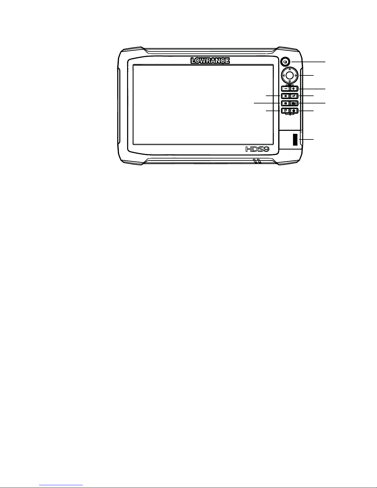
Front - controls
1
2
3
4
5
6
78
910
11
1 Multi-touch touchscreen
2 Pages
3 Cursor (8-way)
4 Zoom out / Zoom in (combined press = MOB)
5 Exit (X)
6 Enter
7 Menu (short press = menu, long press = hide menu bar,
double press = Settings menu)
8 Active panel
9 New waypoint (long press = nd dialogue)
10 Power key (short press = system controls, long press =
power o )
11 Card reader door

10 |
HDS Gen3 overview | HDS Gen3 Installation Manual
Rear - connectors
1
HDS-9 / 12 HDS-7
223 4 5 21453
1 NMEA 2000 - data input / output
2 ETHERNET - high bandwidth data (radar, sonar, chart)
3 POWER - 12V input & NMEA 0183. Optional video-in via
adaptor
4 SONAR - CHIRP and Broadband Sonar
5 STRUCTURE - StructureScan HD sonar
| 11
HDS Gen3 overview | HDS Gen3 Installation Manual
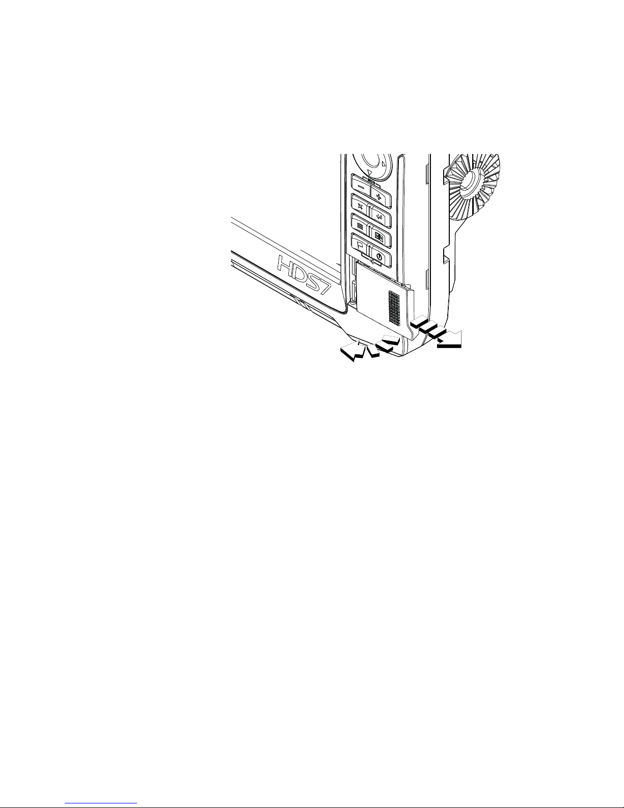
MicroSD card slot
Used for detailed chart data, software updates, transfer of user data
and system backup. All size displays have two card reader slots.
The card reader door is opened by sliding the door to the right (1)
using your ngernail, then hinging forward (2) from the right hand
side.
2
1
The card reader door should always be shut immediately after
inserting or removing a card, in order to prevent possible water
ingress.
12 |
Check the contents | HDS Gen3 Installation Manual
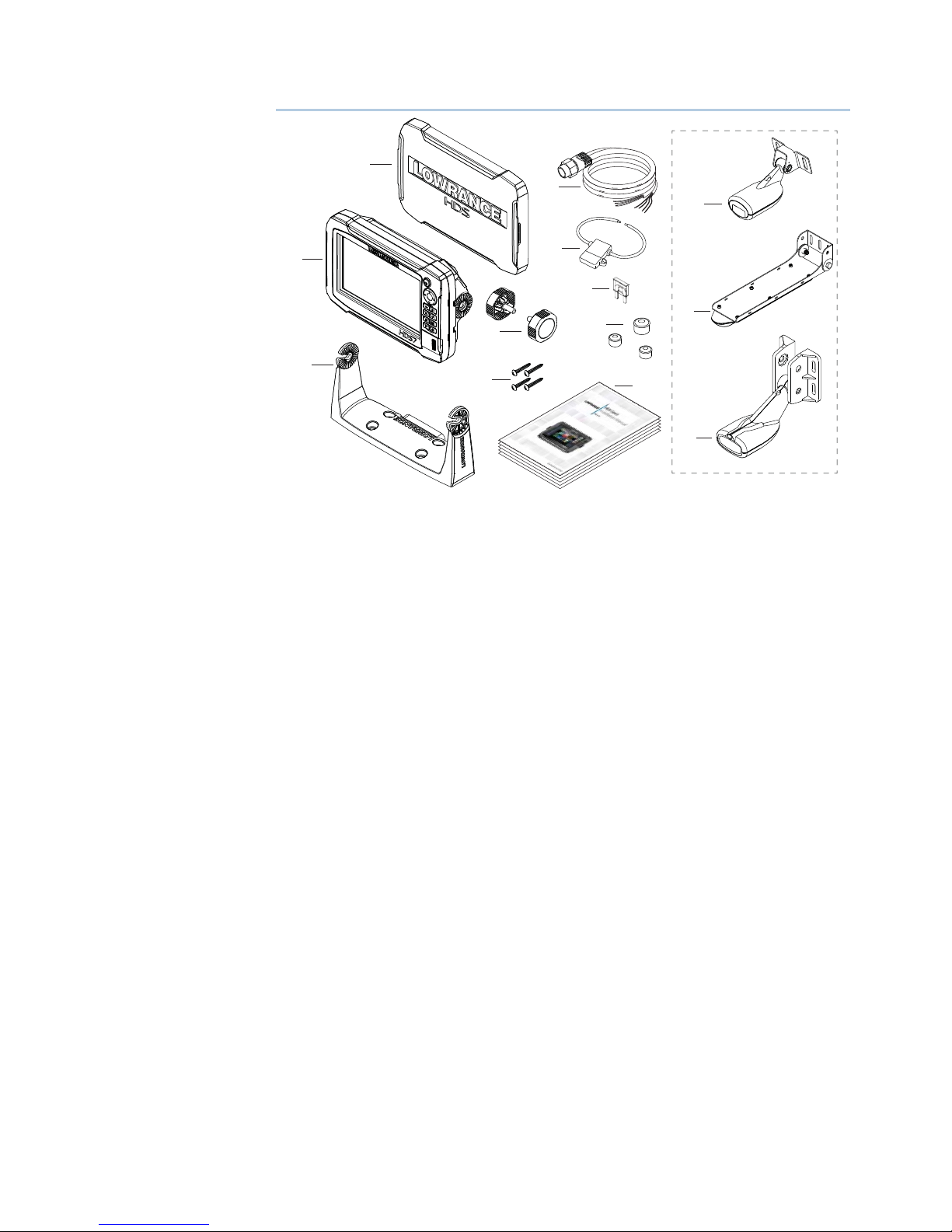
Check the contents
7
9
8
11
12
13
10
1
2
3
4
5
6
1 HDS Gen3 display
2 Suncover
3 Bracket
4 Knobs
5 Fasteners (4 x 6G x 1.5 panhead PH1)
6 Power cable
7 Fuse holder (ATC blade)
8 Fuse (3 amp)
9 Caps (3x for HDS7 4x for HDS9/12 - for ethernet, NMEA 2000,
StructureScan)
10 Documentation pack (Operator & Installation manual, Quick
guide, warranty card)
11 83/200 kHz transducer (model dependant)
12 StructureScan HD transducer (model dependant)
13 50/200 kHz transducer (model dependant)
2
| 13
Display Installation | HDS Gen3 Installation Manual
Display Installation
Mounting location
Choose the mounting locations carefully before you drill or cut. The
display should be mounted so that the operator can easily use the
controls and clearly see the display screen. Be sure to leave a direct
path for all of the cables. Lowrance displays are high-contrast, and
are viewable in direct sunlight, but for best results install the display
out of direct sunlight. The chosen location should have minimal
glare from windows or bright objects.
Ensure that any holes cut are in a safe position and will not weaken
the boat’s structure. If in doubt, consult a quali ed boat builder, or
marine electronics installer.
Before cutting a hole in a panel, make sure that there are no hidden
electrical wires or other parts behind the panel.
Do not mount any part where it can be used as a hand hold, where
it might be submerged, or where it will interfere with the operation,
launching or retrieving of the boat.
If bracket mounting the display, choose an area where the display
will not be subjected to excessive vibration.
The mounting location may a ect the internal GPS receiver. Test
the unit in it’s intended location to ensure satisfactory reception.
An external GPS source may be added to overcome poor reception
areas.
Leave su cient clearance to connect all relevant cables.
Good ventilation is required. Inadequate ventilation may cause the
display to overheat. Lowrance displays are designed to operate in
temperatures from -15° C to +55° C (+5° F to +131° F).
For overall width and height requirements, please see the
dimensions section on page 53.
!
Warning: When installing the displays, ensure appropriate
safety equipment is used, eg. ear mu s, protective glasses, gloves
and a dust mask.
Power tools may exceed safe noise levels, and can cast o
dangerous projectiles.
The dust from many materials commonly used in boat
construction may cause irritation or damage to eyes, skin, and
lungs.
3
14 |
Display Installation | HDS Gen3 Installation Manual
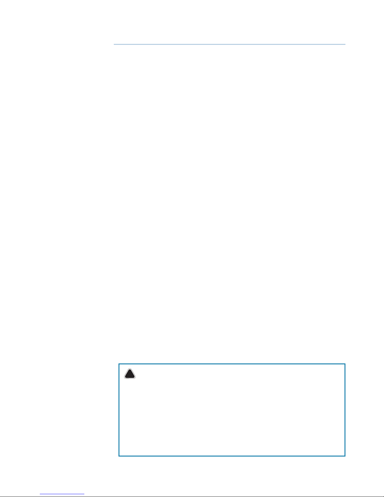
Bracket mounting
Place the bracket in the desired mounting location, and use a pencil
or permanent marker to mark drilling locations.
Note: ensure that the chosen location has enough height to
accomodate the display tted in the bracket, and allows tilting of
the display. Also adequate space is required on both sides to allow
tightening and loosening of the knobs.
Use fasteners suited to the mounting surface material. If the material
is too thin for self tappers, reinforce it, or mount the bracket with
machine screws and large washers. Use only 304 or 316 stainless
steel fasteners. Mark the screw locations using the bracket as a
template, and drill pilot holes.
Screw down the bracket.
Mount the display to the bracket using the knobs. Hand tighten
only. The ratchet teeth in the bracket and display case ensure a
positive grip and prevent the unit changing from the desired angle.
| 15
Display Installation | HDS Gen3 Installation Manual
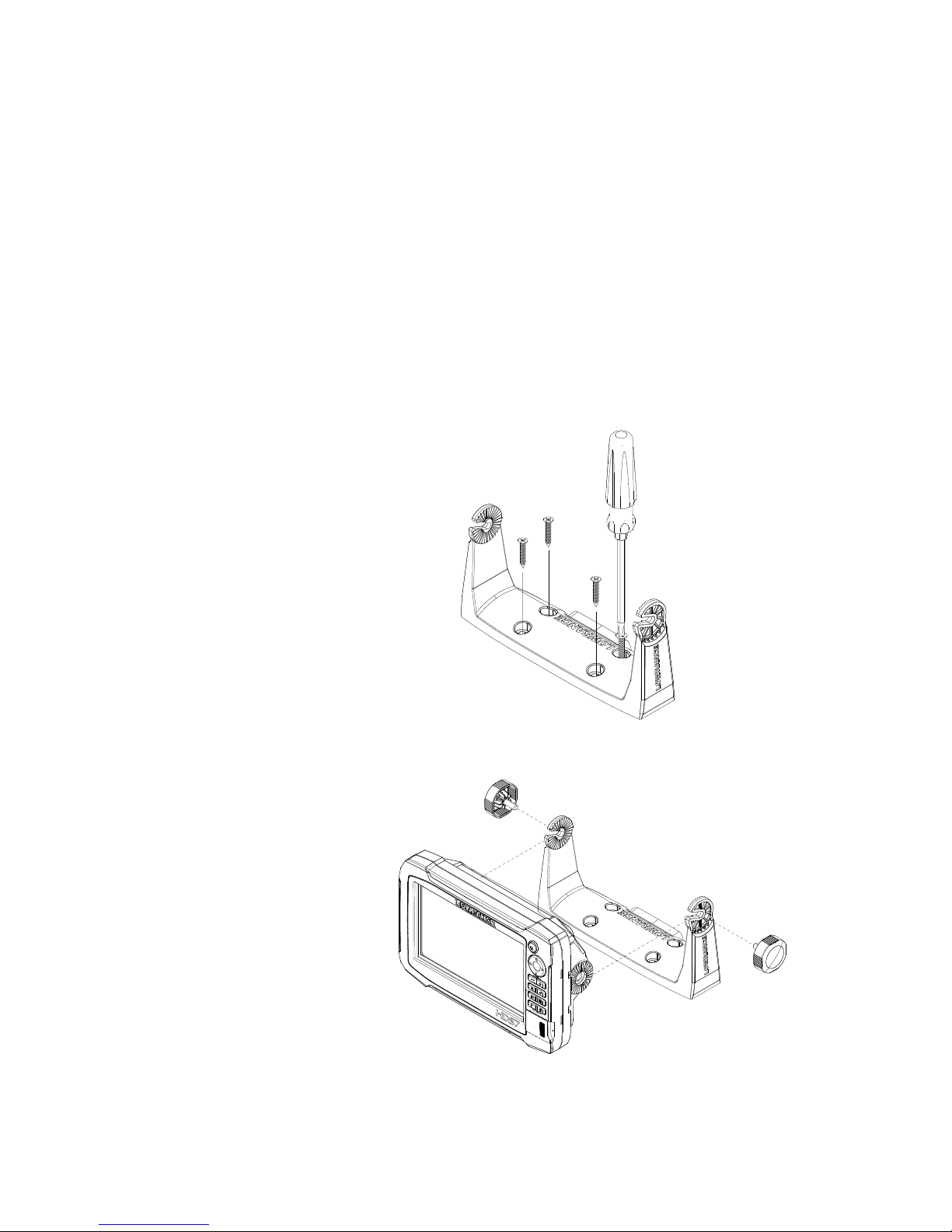
Flush mounting
Check the template for scaling accuracy, using a tape measure or
ruler against the ruler printed on the template.
Cut away excess paper, and tape down
the template. Check that it is correctly
aligned to a vertical or horizontal
reference. Do not use a bubble level as
vessel may be unlevel! Adjust where
required.
Drill all marked pilot holes, then using an
appropriate saw, cut through the
template and mounting surface, along
the dotted line bordering the shaded
center of the template.
Remove the bezel from the display
by rst opening the card reader
door. Using a ngernail or small at
screwdriver, pull o the bezel at the
slotted points immediately above
and below the card reader. Pull bezel
around keypad forward, till hidden
tab at top right can be disengaged
by a slight downward pull. Applying
a slight twist to top bezel edge will
disengage the top left hidden tab.
The rest of the bezel should come
away easily.
Check the t of the display, and use a le to remove any remaining
obstructions. If water-tightness is required, apply a thin, continuous
bead of sealant to the back of the display prior to nal installation.
Sealant should be of a ‘neutral cure’ type to prevent damage to the
plastics. Secure the display with the supplied screws. Once screws
are fully tightened, ensure there
is complete contact with the
mounting surface. Lastly, install
the bezel with the card reader
door open; insert the outermost
tabs on the bezel into the slots
on the display, then gently press
down the bezel above and
below the card reader door until
it clicks in to place.
MOUNTING SCREW SIZE IS #6 TAPPING SCREW
L
C
L
C
Check dimensions before cutting
SUN COVER
PRODUCT OUTLINE
199.0 mm (7.83")
190.5 mm (7.50")
220.4 mm (8.68")
95.3 mm (7.50")
99.5 mm (3.92")
95.3 mm (7.50")
110.2 mm (3.75")
16 |
Mounting the transducer | HDS Gen3 Installation Manual
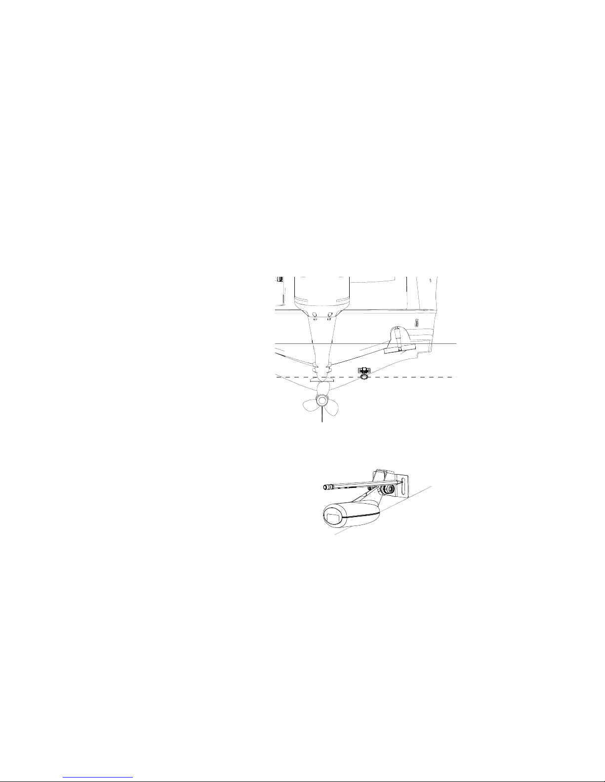
Mounting the transducer
Transducer location selection and installation are two of the
most critical steps in sonar installation. To function properly the
transducer must be in the water at all times, and in a location that
has a smooth ow of water while the boat is moving.
Research
Before starting the installation of the transducer, it’s advised to
check the following:
• Find out if the boat builder has a recommended installation location
• Establish direction of rotation of the propeller(s)
• Watch actual water ow when boat is travelling at cruising speed to
determine the area of transom with the cleanest ow (least bubbles)
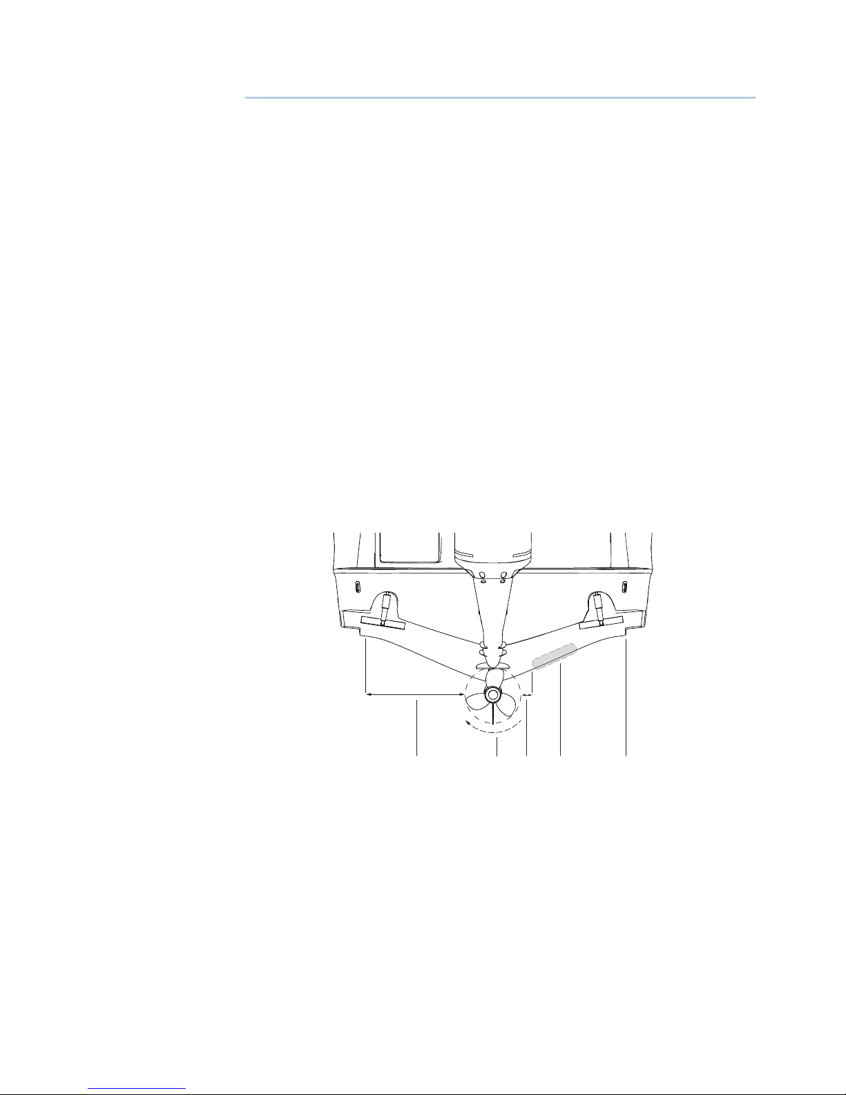
Select a transducer location
The primary aim is to stay clear of propeller and hull generated
turbulence, while mounting the transducer as close to the center of
the vessel as possible.
1
2
3
5
4
1 Avoid mounting within 1 m (3.3’) to port (left) of propeller
2 Conventional clockwise propeller rotation
3 Avoid mounting within 7.5 cm (3“) to starboard of propeller
4 Best mounting location - undisturbed water ow
5 Planing strake - avoid mounting behind here
Note: Reverse the distance guides (1 & 3) from propeller where
engine is of counterclockwise con guration.
4
| 17
Mounting the transducer | HDS Gen3 Installation Manual
Note: Boats with strakes or ribs on the hull can create large amounts
of turbulence at higher speeds. A good transducer location on these
types of boats is between the ribs closest to the engine.
Note: If the transducer is not placed in a smooth ow of water,
interference caused by bubbles and turbulence may show onscreen in the form of random lines or dots. The unit could also lose
bottom signal when the boat is on plane.
Note: Trim tabs will vary in the amount of turbulence they create as
they are adjusted, stay clear of these.
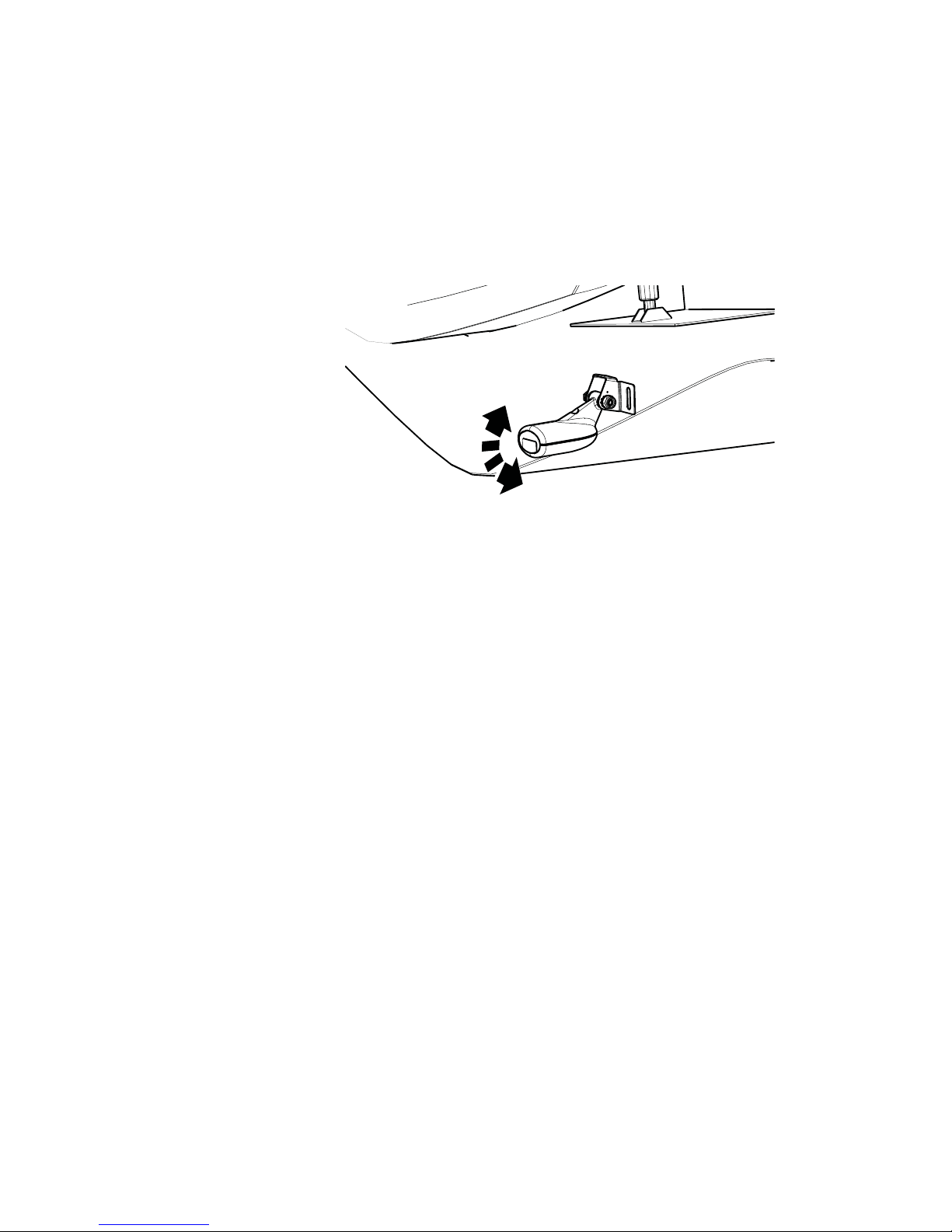
Attaching the transducer
The transducer should be installed parallel with the transom’s
waterline, not the bottom of the boat (deadrise).
Note: Ensure the entire bottom surface of the transducer hangs at
least 3 mm (1/8th of an inch) lower than the bottom of the hull.
Hold the transducer with bracket up to the transom of the boat
and trace the slotted screw hole locations (two on the 83/200 KHz
transducer, and four on the 50/200 KHz transducer). Mark drilling
points in the middle of each outline, to allow for transducer height
adjustment. Drill pilot holes to suit fasteners.
Note: Check that there is nothing on the other side of the mounting
surface that may be damaged by drilling.
Attach transducer to transom, using supplied stainless steel
fasteners. Drill a 25 mm (1”) hole above the waterline, large enough
to pass the plug through.
18 |
Mounting the transducer | HDS Gen3 Installation Manual
Secure the cable to the hull at regular intervals using cable P clips or
saddles and ensure that moving parts such as an outboard motor or
boarding ladder can’t snag the cable.
Adjusting the transducer
If the sonar image shows interference lines on the screen when
moving, which worsen with speed, it may be possible to eliminate
these by adjusting the transducer’s angle.
Note: A transducer that is tilted too far in either direction will not
perform well; missing targets, and/or losing the bottom at speed.
If performance does not improve with tilting, try adjusting the
height of the transducer relative to the transom of the boat. If the
transducer is too high it may be seeing cavitation caused by the
trailing edge of the transom.
 Loading...