

Page 1

988-0176-06_A
HDS unit installation instructions
Read the following instructions carefully before attempting any installation.
Transducer installation recommended tools and supplies
(not included)
If you plan to route the transducer cable through the transom, you will need either
a 1" drill bit or a 5/8" drill bit depending on the size of the transducer cable connector. Each transom mount requires a high quality, marine grade above- or belowwaterline sealant/adhesive compound. The following installations also call for these
recommended tools and supplies.
One-piece bracket transom installation:
Tools: two adjustable wrenches or socket wrench, drill, #29 (0.136") drill bit, screwdriver. Supplies: none.
Two-piece bracket transom installation:
Tools: two adjustable wrenches or socket wrench, drill, #20 (0.161") drill
bit, screwdriver. Supplies: four, 1" long, #12 stainless steel wood screws.
TMB-S bracket trolling motor installation:
Tools: two adjustable wrenches or socket wrench, screwdriver. Supplies:
plastic cable ties.
Skimmer Transducer shoot-through hull installation:
Supplies: alcohol wipes, 60 and 160 grit sandpaper, and marine grade
above- or below-waterline epoxy adhesive.
Pod Transducer shoot-through hull installation:
Supplies: alcohol wipes, 60 and 160 grit sandpaper, and marine grade
above- or below-waterline epoxy adhesive.
1
Page 2
Skimmer Transducer installation instructions
Transducer location and installation is one of the most critical steps in sonar installation.
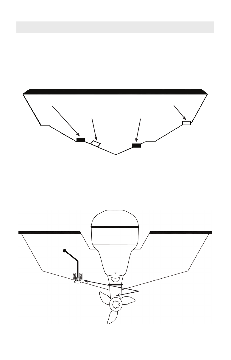
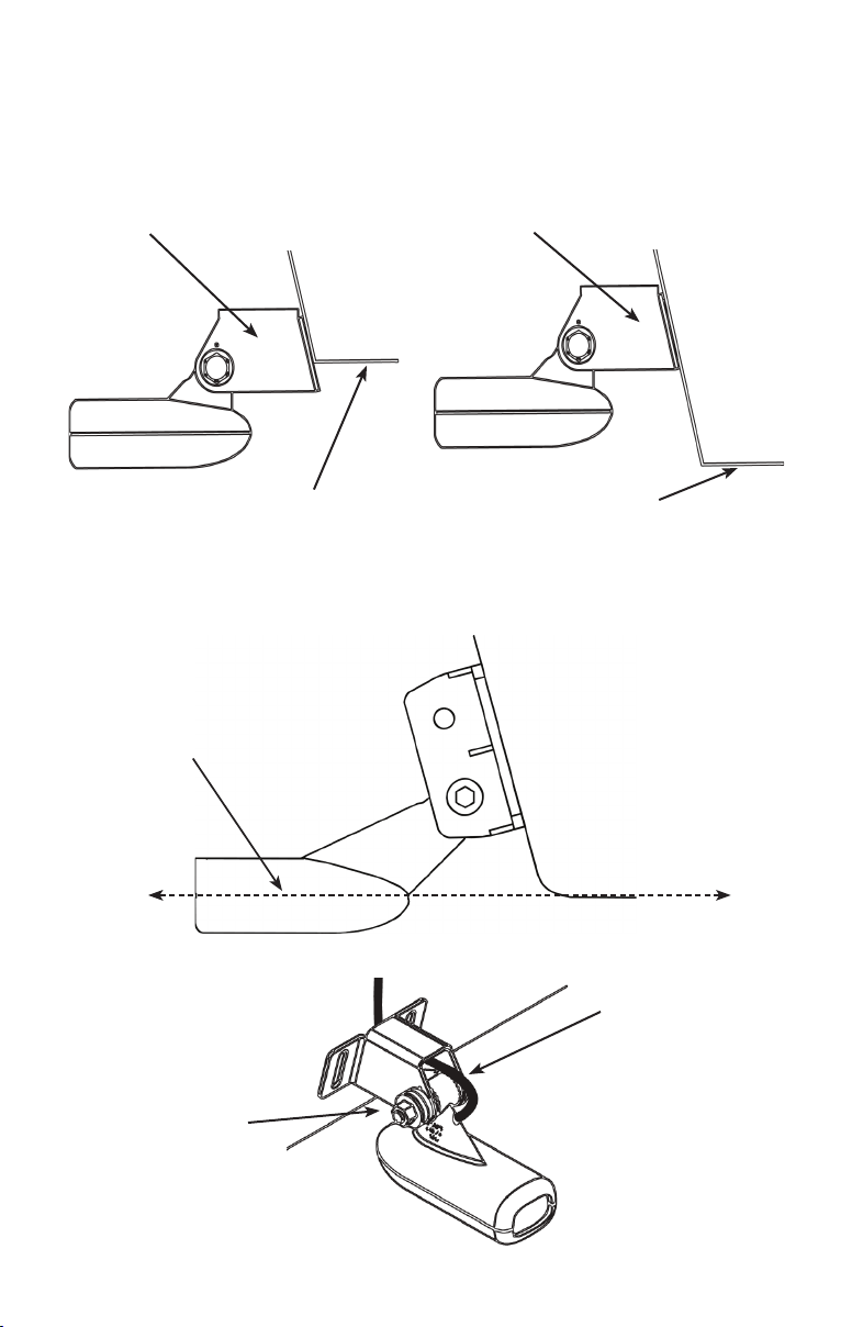
1. Select a transducer location
To function properly the Skimmer transducer must be in the water at all times and in a
location that has a smooth ow of water when the boat is moving.
Good location
Poor location
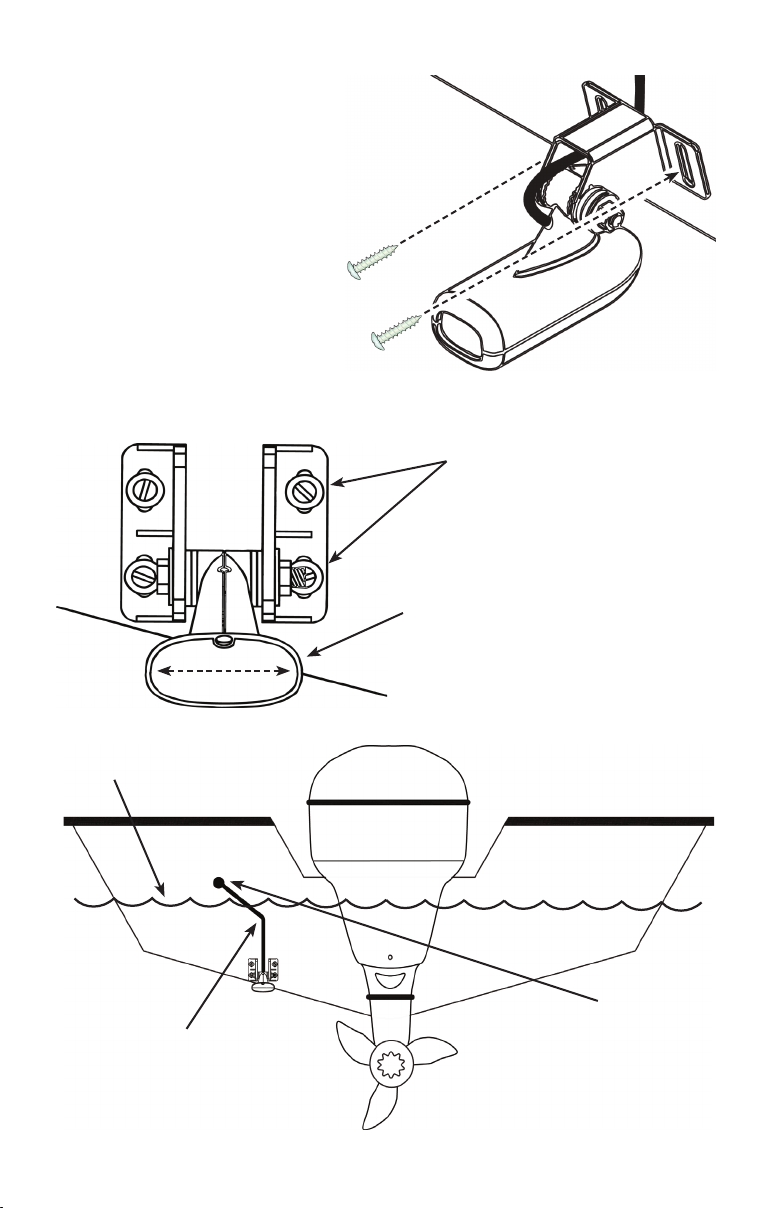
Aluminum boats with strakes or ribs on the hull can create large amounts of
turbulence at higher speeds. A good transducer location on these types of
boats is between the ribs closest to the engine.
Good location
Poor location
If the transducer is not placed in a smooth ow of water, interference caused by
bubbles and turbulence may show on-screen in the form of random lines or dots.
The unit also could lose bottom signal when the boat is on plane.
Do not mount the transducer
closer than approximately one
foot from the engine’s lower
unit. This will prevent cavitation
interference from the prop.
When mounting the transducer, make sure it does not interfere with the haul-
ing of the boat.
2
Page 3
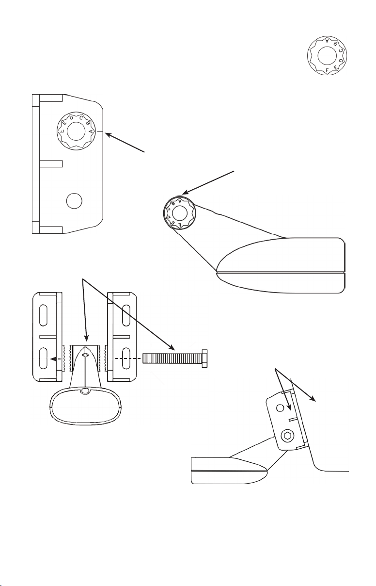
2. Aligning Ratchets on Transducer bracket
Aligning ratchets on one-piece bracket:
The one-piece bracket assembly includes two black plastic ratchets. The ratchets
are used to align the transducer with the boat hull. Each ratchet has the letters A-E
molded into it.
Ratchet
Bracket
2. Slide the transducer in the
bracket and temporarily slide
the bolt through the transducer
bracket, as shown in the image
at right.
1. Insert the ratchets in the bracket with the letter
"A" aligned with the dot stamped on the outside
of the transducer bracket, as shown in the fol-
lowing series of diagrams.
Align dot and
letter "A".
Transom
3. Hold the transducer assembly
against the transom. Look at the
transducer from the side. Try to
adjust the transducer so its face
is parallel to the ground. If it does,
then the "A" position is correct.
If the transducer will not adjust with its face parallel to the ground, remove the
transducer and ratchets from the bracket. Reinsert the ratchets into the bracket, this
time with the letter "B" aligned with the dot stamped in the bracket. Reassemble the
transducer and bracket and place it against the transom. Again, check to see if the
transducer will adjust so its face is parallel with the ground. Repeat this process until
the transducers face will adjust so that it is parallel with the ground.
3
Page 4
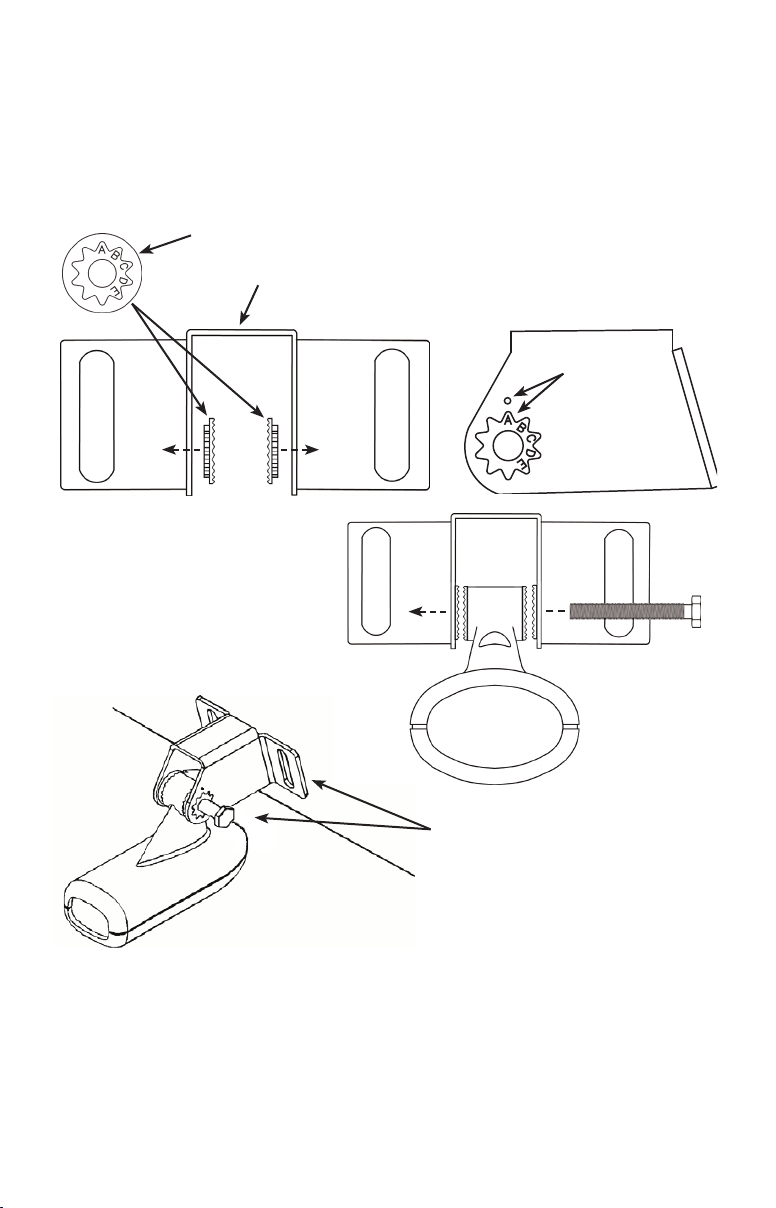
Aligning ratchets on two-piece bracket:
The two-piece bracket includes four black plastic ratchets. The ratchets are used to align the transducer with the boat hull. Each ratchet has
the letters A-F molded into it.
1. Place two of the ratchets in each side of the bracket
with the letter "A" aligned with the alignment mark molded
into each bracket.
2. Now place the other two ratchets on
Alignment
mark
Bracket
3. Slide the transducer in the bracket
and temporarily slide the bolt through
the transducer bracket.
the transducer with the letter "A" aligned
in the 12 o'clock position on the trans-
ducer stem.
4. Hold the transducer assembly
against the transom. Look at the
transducer from the side. Try to
adjust the transducer so its face
is parallel to the ground. If it does,
then the "A" position is correct.
Ratchet
Transom
If the transducer will not adjust with its
face parallel to the ground, remove the
transducer and ratchets from the bracket. Reinsert the ratchets into the bracket,
this time with the letter "B" aligned with
the dot stamped in the bracket. Reassemble the transducer and bracket and place it
against the transom. Again, check to see if the transducer will adjust so its face is
parallel with the ground. Repeat this process until the transducers face will adjust so
that it is parallel with the ground.
4
Page 5
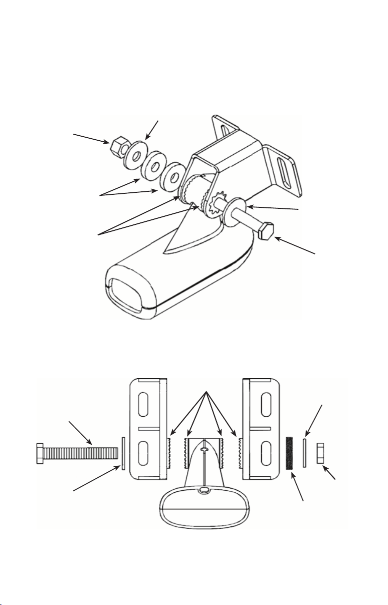
3. Assembling the Transducer bracket
After determining the correct position for the ratchets, loosely assemble the transducer and bracket assembly as shown in one of the two diagrams below.
One-piece bracket assembly:
Metal washer
Lock nut
Rubber washers
Metal washer
Ratchets
Bolt
Do not tighten the transducer bracket assembly until you have aligned the
transducer and bracket on the transom.
Two-piece bracket assembly:
Ratchets
Bolt
Small at washer
Thick rubber washer
Do not tighten the transducer bracket assembly until you have aligned the
transducer and bracket on the transom.
Large at
washer
Lock nut
5
Page 6
4. Aligning and Attaching the Transducer on the Transom
Adjust the transducer so that its "face" is parallel with the ground and its center line
is even with the bottom of the boat hull.
Transducer bracket
mounted too low.
Transom
Bottom of hull.
When mounting the transducer to the transom, there are two extremes you
should avoid, rst, do not let the edge of the mounting bracket extend below
the bottom of the hull, left image, above. Second, do not let the bottom of the
transducer rise above the bottom of the hull, right image, above.
The center line of the transducer
should be level with the bottom of
the boat hull and its "face" parallel
with the ground.
Transducer bracket
mounted too high.
Transom
Bottom of hull.
Transom
Transducer face
Do not over tighten
the transducer bracket
lock nut. If you do, the
transducer may not
"kick-up" if it strikes an
object in the water.
Bottom of hull.
For single frequency
transducers, with a
one-piece bracket,
assemble it with the
cable passing over
the bolt and through
the bracket, as shown
here.
6
Page 7
1. Hold the transducer and bracket assembly against the transom.
When the transducer and bracket
are properly aligned mark its posi-
tion on the hull.
2. Drill the mounting holes for the
transducer bracket. For the onepiece bracket use a #29 bit (for
the #10 screws). For the two-piece
bracket use a #20 bit (for the #12
screws).
Use the provided screws to secure the transducer assembly to the transom.
Be sure to use a below-waterline
marine grade sealant on all of the
transducer bracket screw holes.
When mounting a Skimmer transducer
to a boat with a veehull, make sure the
transducer center line is aligned to the
bottom of the boat hull, as shown here.
Water line
Clamp the transducer cable to
the transom near the transducer.
This will help keep the cable
secure.
If you drill a hole in the transom
for the transducer cable, make
sure it is located above the
waterline. Seal the hole with
an above- or below-waterline
marine grade sealant.
7
Page 8
If you drill a hole in the transom for the transducer cable, make sure it is located
above the waterline. Seal the hole with an above or below waterline marine grade
sealant. Route the transducer cable to the sonar unit. Make sure to leave some slack
in the cable near the transducer.
Use caution when routing the transducer cable near other wiring and cables. If you
need to drill a hole in the transom to pass the connector through, the hole size will
depend on the connector on the end of the transducer’s cable.
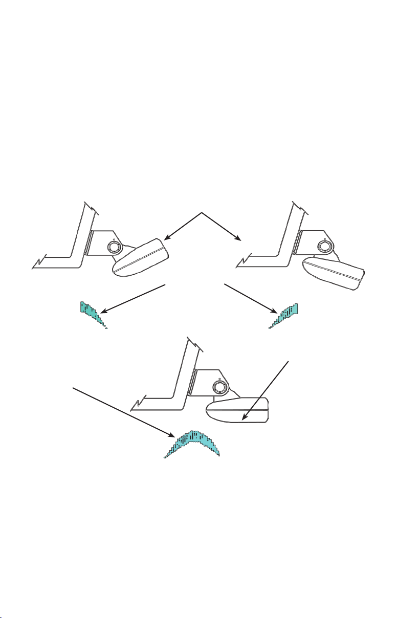
5. Make a test run to determine the results
At times you may need to adjust the transducer higher or lower. The slots in the
mounting brackets allow you to loosen the screws and slide the transducer up or
down.
Improper transducer angles
Partial sonar
sh arches
Transducer face parallel
with the bottom.
Full sonar sh arch
If the sonar screen is displaying partial sh arches, as shown in the previous top
two images, the transducer could be at an improper angle. Check the transducer
and make sure its face is parallel with the bottom, as shown in the bottom example.
If you frequently lose bottom signal lock the transducer may be coming out of the
water as the boat crosses waves or wakes.
Move the transducer a little lower in the water to see if that improves sonar perfor-
mance. When shing around underwater structure the transducer may be kicked up
from object strikes. If the transducer is being kicked up too often, try moving it a
little higher for more protection.
8
Page 9
TMB-S trolling motor bracket installation
The TMB-S bracket is designed for one-piece bracket transducers only.
The TMB-S trolling motor bracket (Part No. 51-45) is an optional accessory and is
available through LEI Extras at www.lei-extras.com. The TMB-S bracket is used
to attach a one-piece bracket transducer to a trolling motor. If you regularly sh in
water with a lot of underwater structure, such as rocks, stumps and trees, you may
consider using a Pod transducer for trolling motor installation. Pod transducers cannot be "kicked up" by underwater structure.
Internal tooth washer
Plastic bracket
Bolt
Lock nut
Flat washer
Using the components supplied with the TMB-S bracket (adjustable strap, internal tooth washer and plastic bracket) attach it to the transducer as shown
in the diagram above.
Adjustable strap
Route the transducer cable along the trolling motor shaft. Use plastic ties
(not included) to secure
the cable to the shaft.
Slide the adjustable strap through the plastic bracket as shown above, left,
then slip the strap around the trolling motor as shown in the image, at right.
Position the transducer so its "face" is pointing straight down when the trolling motor is in the water. Tighten the adjustable strap securely to the trolling
motor. Make sure there is enough slack in the transducer cable for the trolling
motor to turn freely.
9
Page 10

Skimmer Transducer shoot-thru-hull installation
Before attempting any installation on boats with otation material sandwiched
within the hull, consult the boat manufacturer. In a shoot-thru-hull installation the
transducer is epoxied to the inside of the boat hull.
WARNING: Do not remove any material from the inner hull.
Careless grinding or cutting on the hull could damage the integrity of the hull. Contact the boat dealer or manufacturer to
conrm hull specications
.
Transducer
Transducer epoxied to hull.
The previous image shows a Skimmer transducer epoxied to a at, solid portion of the boat hull near the transom. The circled image is a close-up view of
the transducer epoxied to the hull.
On vee hulls try to place the transducer
where the dead rise is 10° or less.
Epoxy
Hull
NOTE: While you can epoxy a Skimmer transducer to the
inside of a boat hull, we recommend using a Pod transducer for this type of installation. Use care when mounting a
transducer inside a boat hull. Once epoxied into position,
the transducer can be very difcult to remove.
10
Page 11

A transducer can not shoot through wood or metal hulls. Wood and metal hulls
require either a transom mount or "thru-hull" installation. For shoot-thru-hull appli-
cations many boat hulls have a at keel pad that offers a good transducer mounting
surface.
If you are using a Skimmer transducer versus a Pod transducer for this installation,
make sure the Skimmer transducer is oriented so the nose of the transducer is facing
the bow (front) of the boat. Also, if the transducer has a built in temp sensor, it will
only show the temperature of the hull, not the water temp.
Before you epoxy the transducer to the hull, make sure the area is clean, dry and free
of oil or grease. The surface of the hull must be at so the entire transducer face is
in contact with the hull. Also, make sure the cable is long enough to reach the sonar
unit.
Sand both the inside surface of the hull,
1. Sand face
of transducer
and bottom of
hull.
where the transducer is to be epoxied, and
the face of the transducer.
Start with a rougher grit sandpaper, such
as 60 grit, and nish with a smoother grit,
such as 160 grit, sandpaper. Sand the inside surface of the hull until it is smooth
to the touch.
2. Apply epoxy to face
of transducer
and bottom of
hull.
The sanded area should be about 1-1/2
times the diameter of the transducer. After sanding, clean the hull and face of the
transducer with an alcohol wipe to remove
any sandpaper grit and dust.
3. Epoxy transducer to hull.
Epoxy
Apply a thin layer of epoxy (about 1-16"
or 1.5 mm) on the face of the transducer
and the sanded area on the hull. Make
sure there are no air pockets in the epoxy layers.
Hull
Press the transducer into the epoxy, twist-
To bow
ing and turning it to force any air bubbles
out from under the transducer face. Stop
pressing when it bottoms out on the hull.
Apply pressure to hold the transducer in place while the epoxy sets. Be careful not
to move the transducer while the epoxy is setting. Allow the epoxy to set before
moving the boat. When nished, the face of the transducer should be parallel with
the hull with a minimum amount of epoxy between the hull and transducer. After the
epoxy has set, route the transducer cable to the sonar unit.
11
Page 12

Pod Transducer installation instructions
The following instructions explain how to install a Pod transducer inside a hull or
on a trolling motor. Read the following instructions carefully before attempting any
installation. Use extreme care when mounting a transducer inside a boat hull. Once
epoxied into position, the transducer can be very difcult to remove.
NOTE: Transducer location and installation is one of the
most critical steps in sonar installation.
Pod Transducer shoot-thru-hull installation
Before attempting any installation on boats with otation material sandwiched within the hull, consult the boat manufacturer.
WARNING: Do not remove any material from the inner hull.
Careless grinding or cutting could damage the integrity of the
hull. Contact the boat dealer or manufacturer to conrm hull
specications
A transducer can not shoot through wood or metal hulls. Wood and metal hulls
require either a transom mount or "thru-hull" installation. For shoot-thru-hull appli-
cations many boat hulls have a at keel pad that offers a good transducer mounting
surface.
.
Transducer
Transducer epoxied to hull.
The previous image shows a Pod transducer epoxied to a at, solid portion of
the boat hull near the transom. The transducer should be installed as close to
the transom as possible, close to the center line.
Epoxy
Hull
Before you epoxy the transducer to the hull, make sure the area is clean, dry and free
of oil or grease. The surface of the hull must be at so the entire transducer face is
in contact with the hull. Also, make sure the cable is long enough to reach the sonar
unit before the transducer is epoxied into place.
12
Page 13

On vee hulls try to place the transducer
where the deadrise is 10° or less.
3. Epoxy transducer to hull.
Epoxy
1. Sand face
of transducer
and bottom of
hull.
2. Apply epoxy to face
of transducer
and bottom of
hull.
Sand both the inside surface of the hull,
where the transducer is to be epoxied,
and the face of the transducer.
You may want to start with a rougher
grit sandpaper, such as 60 grit, and nish with a smoother grit, such as 160 grit,
sandpaper. Sand the inside surface of the
hull until it is smooth to the touch.
The sanded area should be about 1-1/2
times the diameter of the transducer. After sanding, clean the hull and face of the
transducer with an alcohol wipe to remove any sandpaper grit and dust.
Apply a thin layer of epoxy (about 1-16"
or 1.5 mm) on the face of the transducer
and the sanded area on the hull. Make
sure there are no air pockets in the epoxy layers.
Press the transducer into the epoxy, twisting and turning it to force any air bubbles
out from under the transducer face. Stop
pressing when it bottoms out on the hull.
Hull
After the epoxy has set, route the
transducer cable to the sonar unit.
Apply pressure to hold the transducer in
place while the epoxy sets. Be careful not
to move the transducer while the epoxy
is setting. Allow the epoxy to set before
moving the boat.
When nished, the face of the transducer
should be parallel with the hull with a
minimum amount of epoxy between the
hull and transducer.
13
Page 14

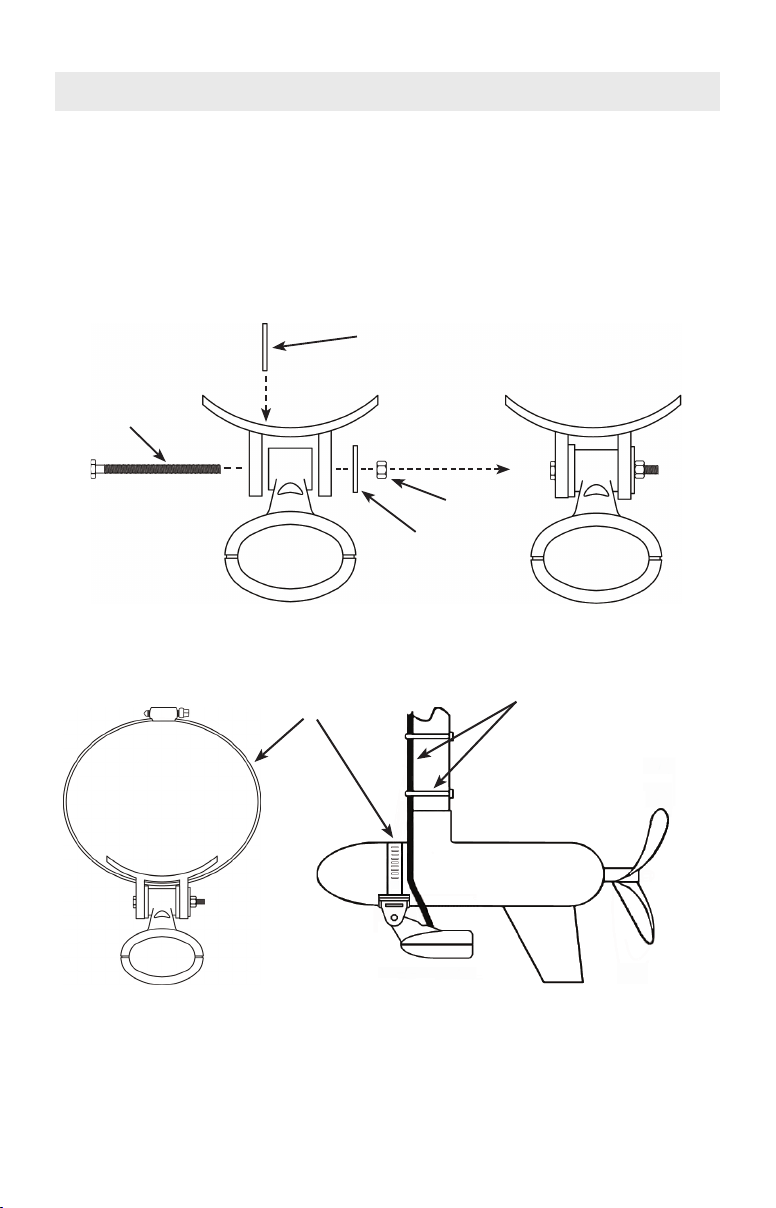
Pod Transducer trolling motor installation
The top of the
transducer is
curved to t
the contour
of the trolling
motor.
You will need a hose clamp large enough to
t over the trolling motor. The hose clamp
is NOT included with the Pod transducer.
Before you attach the transducer to the
trolling motor, make sure there is enough
slack in the transducer cable for the trolling
motor to turn freely.
1. Slide the hose clamp
through the Pod transducer
brackets, as shown below.
The transducer should be mounted ahead of the trolling motor n. Position
the transducer to so its face is pointing straight down when the trolling motor
Cable ties Cable ties
2. Slip the clamp around the trolling motor, as
shown below. Tighten the hose clamp securely to
the trolling motor.
is in the water.
Hose
clamp
Transducer
Route the transducer cable along the trolling motor shaft. Use plastic ties
(not included) to secure the cable to the shaft.
Hose
clamp
14
Page 15

Transducer maintenance
Periodically wash the face of the transducer with soap and water to remove any oil
lm or debris build-up. Oil and other materials on the transducer's face can hamper
its performance. Cleaning will ensure longevity and proper performance of the device.
15
Page 16

Mounting the Unit: Gimbal bracket or In-dash
The unit comes with a gimbal bracket so you can mount it on a dash. The unit also
ships with an in-dash template and four screws for in-dash installations. Determine
the mounting location for the unit. Screws to secure the gimbal bracket to a dash are
not included with the unit.
Gimbal bracket installation
NOTE: Before beginning any installation, read the
following instructions carefully and double check all
cable lengths to make sure the cables will reach the
power source, unit, GPS antenna-receiver module,
transducer, etc.
Holes in the gimbal bracket’s base allow for wood screw or through-bolt mounting.
When mounting the unit using the gimbal bracket, make sure there is enough clearance behind the unit to allow for tilting of the unit and connection of the various
cables.
The gimbal bracket arms
should slope toward the
front of the unit.
1. Use the gimbal bracket as a template
and mark the mounting holes, including
the center hole for the cables.
2. Drill a 1-inch (25.4 mm) hole for the sonar, power/data, Ethernet and network
cables. The large center hole in the gimbal bracket will be used to pass these
cables through.
16
Page 17

3. Use screws or bolts to secure the gimbal bracket to the mounting surface.
4. Pass all the cable connectors through the 1-inch hole in the center of the gimbal
bracket. Leave enough slack in the cables to allow for tilting of the unit.
17
Page 18

Gimbal bracket
knob
4. Secure the unit to the gimbal bracket using the gimbal bracket knobs.
Cable
connectors
Gimbal bracket
knob
Sockets
Sockets
5. Match up the cable connectors to the sockets on the back of the unit. Each cable
and socket is labeled. Attach the proper connector to each socket. Power up the unit
to make sure all the connectors are securely fastened to the proper socket.
18
Page 19

In-dash installation
The unit ships with an in-dash template and four #6 – 20 X 1-1/2" screws. Before
cutting any holes in the mounting surface make sure there is enough room to attach
the cable connectors behind the unit. Begin by taping the in-dash template to the
mounting surface.
Use a #31 (0.120") drill bit
for the four pilot holes.
The template included with your unit will have the proper measurements writ-
ten on it, including the size of the hole saw to use to drill the corner holes
shown in the following step. Cut only on the dotted lines indicated by the
template.
The four corner holes
are indicated by these
shaded areas.
Use a hole saw to drill the four corner holes indicated by the shaded areas
on the template above. Using a hole saw to cut the four corners will ensure
smoother, and more rounded, corners for the in-dash installation.
19
Page 20

To remove the rest of
the material from the
mounting surface (in-
dicated by the shaded
area) cut along these
dotted lines.
After cutting the four corner holes, use a saw to cut along the dotted lines
from hole to hole. Be sure to cut along the inner dotted line, not the outer
solid line.
This diagram shows the sequence for
securing the unit to the mounting surface.
1) Place the unit in the hole cut into the
mounting surface. 2) Use the provided
screws to secure the unit to the mounting
surface.
Mounting surface
3) The face of the unit may
Bezel
If water penetration is a concern, use a marine grade sealant between the unit
and mounting surface.
or may not have adhesive
strips around it. If it does,
peel the plastic cover from
the adhesive strips before
attaching the bezel. 4) Attach
the bezel to the unit.
20
Page 21

Connectivity
Combination Sonar/GPS units
Sonar Network
Power/Data
ENET (Ethernet)
GPS only units
Power/Data
ENET (Ethernet)
Network
21
Page 22

Power / Data cable wiring diagram
Unit
The yellow wire is the
Accessory Wake Up line.
Power cable (3 wire)
Data cable (5 wire)
Power/Data cable
Red (+) wire
with fuse and
fuse holder.
Black (-) wire
Battery
The diagram above shows how the Power/Data cable connects to power.
Yellow TX (+)
Blue TX (-)
Orange RX (+)
Green RX (-)
Shield (ground)
The Data cable wires are used for
the NMEA 0183 and RS-422 hook
up; also, RS-232 and RS-422 for
HDS-8 and HDS-10 models. Refer
to the detailed drawings on the fol-
lowing pages.
22
Page 23

Multiple unit wiring diagram with devices
Ethernet cables
NEP-1
Fuse and fuse holder. The
red wire from each power ca-
ble should be fused between
the device and the battery.
The diagram above shows two HDS units and an LBS-1 connected via an
NEP-1. The power cable from each device contains a yellow wire. The yellow
wire is the Accessory Wake Up line. Connect the yellow wires together. When
the Accessory Wake Up line is used to connect units with the accessory wake
up feature, you can power up certain connected devices from one location,
including digital sonar optimizers and expansion ports.
The four yellow wires (Aces-
sory Wake Up lines) from
each power cable should be
LBS-1
wired together.
23
Page 24

Data cable wiring diagram: HDS-8 & HDS-10 units
NMEA 0183 wiring (data cable)
To exchange NMEA 0183 data, the HDS-8 and HDS-10 units have a NMEA 0183
version 2.0 (RS-422) communication port. Serial Communications Port one (Com
1) can be used to transmit or receive NMEA format data. Two RS-232 ports (Com 1
and Com 2) also are available via software selection. These ports transmit or receive
NMEA data.
The ve wires for the serial communications ports (Data cable) are combined with
the Power cable to form the Power/Data cable.
• Com 1 (RS-422) uses the yellow and blue wires to transmit, the
orange and green wires to receive and the shield (bare) wire for
signal ground.
Power/Data cable
Com 1 to unit
(RS-422)
Yellow TX (+)
Blue TX (-)
Orange RX (+)
Green RX (-)
Shield (ground)
24
Receive (+)
Receive (-)
Transmit (+)
Transmit (-)
Ground
Data cable
To device
Page 25

Data cable wiring diagram: HDS-8 & HDS-10 units
NMEA 0183 wiring (data cable)
• Com 1 (RS-232) uses the yellow wire to transmit, orange wire to
receive and shield (bare) wire for signal ground.
• Com 2 (RS-232) uses the blue wire to transmit, green wire to
receive and shield (bare) wire for signal ground.
Power/Data cable
Com 1 to unit
(RS-232)
Com 2 to unit
(RS-232)
Yellow TX
Orange RX
Shield (ground)
Blue TX
Green RX
Shield (ground)
Receive
Transmit
Ground
Receive
Transmit
Ground
Data cable
To device
To device
25
Page 26

Data cable wiring diagram: HDS-5 & HDS-7 units
NMEA 0183 wiring (data cable)
To exchange NMEA 0183 data, the HDS-5 and HDS-7 units have a NMEA 0183
version 2.0 (RS-422) communication port. Serial Communications Port one (Com
1) can be used to transmit or receive NMEA format data. The ve wires for the serial communications ports (Data cable) are combined with the Power cable to form
the Power/Data cable.
• Com 1 (RS-422) uses the yellow and blue wires to transmit, the
orange and green wires to receive and the shield (bare) wire for
signal ground.
Data cable
Power/Data cable
Com 1 to unit
(RS-422)
Yellow TX (+)
Blue TX (-)
Orange RX (+)
Green RX (-)
Shield (ground)
26
Receive (+)
Receive (-)
Transmit (+)
Transmit (-)
Ground
To device
Page 27

Blank Page
27
Page 28

www.lowrance.com
*988-0176-06*
Visit our website:
© Copyright 2008
All Rights Reserved
Navico Holding AS
28
 Loading...