

Page 1

H.264, Easy Connect, Internet Remote Viewing
DIGITAL VIDEO SURVEILLANCE RECORDER
INSTRUCTION MANUAL
English Version 1.0
MODEL:
LH600 SERIES
Copyright © 2010 Lorex Technology Inc.
www.lorextechnology.com
Page 2
Thank you for purchasing this product. Lorex is committed to providing our customers
with a high quality, reliable security solution.
This manual refers to the following model(s):
• LH604501
For more information on this product, firmware updates, and accessory products, please
visit us at:
www.lorextechnology.com
CAUTION
RISK OF ELECTRIC SHOCK
DO NOT OPEN
CAUTION: TO REDUCE THE RISK OF ELECTRIC SHOCK DO NOT
REMOVE COVER. NO USER SERVICABLE PARTS INSIDE.
REFER SERVICING TO QUALIFIED SERVICE PERSONNEL.
The lightning flash symbol within an equilateral triangle is intended
to alert the user to the presence of uninsulated "dangerous voltage"
within the products ' enclosure that may be of sufficient magnitude
to constitute a risk of electric shock.
The exclamation point within an equilateral triangle is intended to
alert the user to the presence of important operating and
maintenance (servicing) instructions in the literature accompanying
the appliance.
WARNING: TO PREVENT FIRE OR SHOCK HAZARD, DO NOT
EXPOSE THIS UNIT TO RAIN OR MOISTURE.
CAUTION: TO PREVENT ELECTRIC SHOCK, MATCH WIDE BLADE
OF THE PLUG TO THE WIDE SLOT AND FULLY INSERT.
Page 3

NEED HELP?
CONTACT US FIRST
DO NOT R E T U R N THIS PRODUCT TO TH E STORE
Please make sure to register your product at www.lorextechnology.com to receive product updates and information
3 EASY WAYS TO CONTACT US:
Online:
Pr o du c t S up p or t is av a il a bl e 24 / 7 i nc l ud i ng pr o duc t
in f or m ati o n, u se r m a nu a ls, q ui c k s ta r t u p g u id e s a nd FA Q’s
at www.lorex t e c hnology.com/suppor t
To o r de r a c ces s or i es , vi s it
www.lorex technology.com
By Email:
Te ch n ic a l S upp o rt (f o r t ec h nic a l/ i ns t al l at i on i ss u es )
supp o r t @lorexcorp.com
Cu s to m er Ca r e ( f or wa r ra n ty an d ac c es s or y sa l es )
cust o m e rser v i ce@lorexcorp.com
Cu s to m er Fe e db a ck
info @ l o rexcorp. c om
By Phone:
NORTH AMERICA:
CUSTOMER SERVICE: 1-888-425-6739 (1-888-42-LOREX)
TECH SUPPORT: 1-877-755-6739 (1-877-75-LOREX)
MEXICO: 1-866-427-6739
INTERNATIONAL: +800-425-6739-0
(Ex am pl e: Fr om th e UK, di al 00 inst ea d o f +)
Ve rs i o n 8 - A pr i l 2 7 20 1 0
Page 4

NECESITA AYUDA
VOUS AVEZ BESOIN
D’AIDE?
COMUNÍQUESE PRIMERO
CON NOSOTROS
NO DEVUELVA ESTE PRODUCTO A LA TIENDA
Ce rció rese de por favor colocar su producto en www.
lo rexc ctv.c om/r egis trat ion para rec ibir act uali zaci one s y la i nformación del producto
3 maneras sencillas de comunicarse
con nosotros:
www
En línea:
apoyo al producto disponible 24/7 incluyendo información
del producto, manuales para el usuario, guías de inicio
rápido y pregunt as más frecuentes en
www.lorextechnology.com/support
Para colocar ped idos de accesorios, visi te
www.lorextechnology.com
CONTACTEZ-NOUS
D’ABORD
NE RETOURNEZ PAS CE PRODUIT AU MAGASIN
Veuille z ve ille r à enre gist rer votr e pr odui t à www.
lo rexc ctv.c om/r egis trat ion pour rec evoi r de s mi ses à
jo ur e t l’ information de produit
3 façons faciles de nous c ontacter :
www
En ligne:
le support des p roduits est disponible 24 heures sur 24, 7
jours sur 7, y compris les informations sur les produits, les
guides de l’util isateur, les guides de démarrage rapide et
les f oires à questions
www.lorextechnology.com/support
Pour commander d es accessoires, visitez
www.lorextechnology.com
Por Correo Electrónico:
soporte técnico (para asuntos técnicos/la instalación)
support@lorexcorp.com
O
servicio al clien te (respecto a la garantía y a la venta
de accesorios)
customerservice@lorexcorp.com
Comentarios de c liente
info@lorexcorp.com
Por Teléfono:
L’AMÉRIQUE DU NORD:
ATENCIÓN AL CLIENTE: 1-888-425-6739 (1-888-42-LOREX)
SOPORTE TÉCNICO: 1-877-755-6739 (1-877-75-LOREX)
MEXICO: 1-866-427-6739
INTERNACIONAL: +800-425-6739-0
(Ejemplo: Desde el Reino Unido, marque el 00 en lugar del +)
sus opiniones son bienvenidas en
info@lorexcorp.com
para colocar pedidos de accesorios, visite
Par Courriel:
support techniqu e (pour les questions tech niques et
d’installation) support@lorexcorp.com
OU
service à la clie ntèle (pour les questions de garantie
et les ventes d’ accessoires)
customerservice@lorexcorp.com
Commentaires des clients
info@lorexcorp.com
Par Téléphone:
NORTE AMÉRICA:
SERVICE À LA CLIENTÈLE: 1-888-425-6739 (1-888-42-LOREX)
SUPPORT TECHNIQUE: 1-877-755-6739 (1-877-75-LOREX)
MEXICO: 1-866-427-6739
INTERNATIONAL: +800-425-6739-0
(Exemple: À partir du Royaume-Uni, composez 00 au lieu de +)
nous serions heureux de recevoir vos
commentaires à info@lorexcorp.com pour
commander des accessoires, visitez
www.lorextechnology.com
www.lorextechnology.com
Ve rs i o n 8 - A pr i l 2 7 20 1 0
Page 5
B E F O R E Y O U S T A R T
THIS PRODUCT MAY REQUIRE PROFESSIONAL INSTALLATION
LOREX IS COMMITTED TO FULFILLING YOUR SECURITY NEEDS
• We have developed user friendly products and documentation.
Please read the Quick Start Guide and User Manual before you
install this product.
• Consumer Guides and Video Tutorials are available on our web
site at www.lorextechnology.com/support
• If you require further installation assistance, please visit
www.lorextechnology.com/installation or contact a
professional installer.
• Please refer to the “Need Help” insert for technical support and
customer care information.
• Please note that once the components of this product have been
unsealed, you cannot return this product directly to the store
without the original packaging.
April 27 2010 R3
www.lorexcctv.com
Page 6

AVANT DE
A N T E S D E
COMMENCER
CE PRODUIT POURRAIT EXIGER UNE
INSTALLATION PROFESSIONNELLE
LOREX S’ENGAGE À SATISFAIRE
VOS BESOINS SÉCURITAIRES
• Veuillez lire le guide de démarrage rapide et le
mode d’emploi avant d’installer ce produit.
• Les guides du consommateur et les séances
de tutorat vidéo sont disponibles sur l’Internet en
visitant www.lorextechnology.com/support
• Si vous avez besoin de l’aide pour l’installation,
E M P E Z A R
ESTE PRODUCTO PUEDE EXIGIR UNA
INSTALACIÓN PROFESIONAL
LOREX SE COMPROMETE A SATISFACER
SUS NECESIDADES EN SEGURIDAD
• Favor de leer la guía de instalación rápida y la
guía del usuario antes de instalar este producto.
• Puede conseguir las guías del consumidor y
los cursos en enseñanza video sobre el Internet
visitando www.lorexcctv.com/support
• Si necesita ayuda para la instalación, visite
veuillez visiter www.lorextechnology.com/installation
ou contactez un spécialiste en installation
• Veuillez référer à l’insert “Need Help” pour
ob¬tenir de l’information sur le service à la cli-
entèle et le support technique
• Veuillez constater qu’une fois que les
com¬posantes de ce produit ont été retirées de
l’emballage, vous ne pourrez plus retourner ce
produit directement au magasin.
www.lorextechnology.com/installation o contacte un
especialista en instalaciones
• Favor de referir al documento “Need Help” para
obtener información acerca del servicio al cliente
y al soporte técnico
• Favor de notar que una vez que los compo-
nentes de este producto han sido removidos del
embalaje, no podrá devolver este producto di-
rectamente a la tienda
www.lorext echnology.com
April 27 2010 R3
Page 7

TABLE OF CONTENTS
Getting Started . . . . . . . . . . . . . . . . . . . . . . . . . . . . . . . . . . . . . . . . . . . . . . . . . 1
Basic Setup . . . . . . . . . . . . . . . . . . . . . . . . . . . . . . . . . . . . . . . . . . . . . . . . . . . . 2
1. Connect The BNC Cameras . . . . . . . . . . . . . . . . . . . . . . . . . . . . . . . . . . . . . . . . . . . . . . . . . . . . . . . . . . . 2
2. Connect The Mouse . . . . . . . . . . . . . . . . . . . . . . . . . . . . . . . . . . . . . . . . . . . . . . . . . . . . . . . . . . . . . . . . . 2
3. Connect The Ethernet Cable . . . . . . . . . . . . . . . . . . . . . . . . . . . . . . . . . . . . . . . . . . . . . . . . . . . . . . . . . . 2
4. Connect a DVI Display . . . . . . . . . . . . . . . . . . . . . . . . . . . . . . . . . . . . . . . . . . . . . . . . . . . . . . . . . . . . . . . . 3
5. Connect The Power Adapter . . . . . . . . . . . . . . . . . . . . . . . . . . . . . . . . . . . . . . . . . . . . . . . . . . . . . . . . . . 3
6. Verify Camera Image . . . . . . . . . . . . . . . . . . . . . . . . . . . . . . . . . . . . . . . . . . . . . . . . . . . . . . . . . . . . . . . . 3
7. Set The Time . . . . . . . . . . . . . . . . . . . . . . . . . . . . . . . . . . . . . . . . . . . . . . . . . . . . . . . . . . . . . . . . . . . . . . . 3
Connecting The Cameras. . . . . . . . . . . . . . . . . . . . . . . . . . . . . . . . . . . . . . . . . 4
Camera Stand Installation . . . . . . . . . . . . . . . . . . . . . . . . . . . . . . . . . . . . . . . . . . . . . . . . . . . . . . . . . . . . . . 4
Connecting and Removing BNC cables . . . . . . . . . . . . . . . . . . . . . . . . . . . . . . . . . . . . . . . . . . . . . . . . . . . . . . . . . . . 5
Front Panel . . . . . . . . . . . . . . . . . . . . . . . . . . . . . . . . . . . . . . . . . . . . . . . . . . . . 6
Rear Panel . . . . . . . . . . . . . . . . . . . . . . . . . . . . . . . . . . . . . . . . . . . . . . . . . . . . . 7
Control Devices. . . . . . . . . . . . . . . . . . . . . . . . . . . . . . . . . . . . . . . . . . . . . . . . . 8
Remote Control . . . . . . . . . . . . . . . . . . . . . . . . . . . . . . . . . . . . . . . . . . . . . . . . . . . . . . . . .8
System Navigation . . . . . . . . . . . . . . . . . . . . . . . . . . . . . . . . . . . . . . . . . . . . . . 9
Mouse Control . . . . . . . . . . . . . . . . . . . . . . . . . . . . . . . . . . . . . . . . . . . . . . . . . . . . . . . . . . 9
Remote Control Navigation . . . . . . . . . . . . . . . . . . . . . . . . . . . . . . . . . . . . . . . . . . . . . . . . 9
Quickly Access System Information . . . . . . . . . . . . . . . . . . . . . . . . . . . . . . . . . . . . . . . . . . . . . . . . . . . . . . . . . . . . . . 9
Using the System . . . . . . . . . . . . . . . . . . . . . . . . . . . . . . . . . . . . . . . . . . . . . . 10
Powering on/off The System . . . . . . . . . . . . . . . . . . . . . . . . . . . . . . . . . . . . . . . . . . . . . . 10
Logging In To The System . . . . . . . . . . . . . . . . . . . . . . . . . . . . . . . . . . . . . . . . . . . . . . . . 11
Logging Out Of The System . . . . . . . . . . . . . . . . . . . . . . . . . . . . . . . . . . . . . . . . . . . . . . . 12
Using the Virtual Keyboard . . . . . . . . . . . . . . . . . . . . . . . . . . . . . . . . . . . . . . . . . . . . . . . . . . . . . . . . . . . . 12
On-Screen Display . . . . . . . . . . . . . . . . . . . . . . . . . . . . . . . . . . . . . . . . . . . . . . . . . . . . . . 13
Changing Display Modes . . . . . . . . . . . . . . . . . . . . . . . . . . . . . . . . . . . . . . . . . . . . . . . . . 14
Using Auto Sequence . . . . . . . . . . . . . . . . . . . . . . . . . . . . . . . . . . . . . . . . . . . . . . . . . . . . . .14
Quick Menu . . . . . . . . . . . . . . . . . . . . . . . . . . . . . . . . . . . . . . . . . . . . . . . . . . . . . . . . . . . . 15
Understanding the Quick Menu . . . . . . . . . . . . . . . . . . . . . . . . . . . . . . . . . . . . . . . . . . . 15
Searching For Video . . . . . . . . . . . . . . . . . . . . . . . . . . . . . . . . . . . . . . . . . . . . . . . . . . . . . 16
Searching For Video By Time . . . . . . . . . . . . . . . . . . . . . . . . . . . . . . . . . . . . . . . . . . . . . . . . . . . . . . . . . . . 16
Searching For Video By Event . . . . . . . . . . . . . . . . . . . . . . . . . . . . . . . . . . . . . . . . . . . . . . . . . . . . . . . . . . 18
Video Playback Controls . . . . . . . . . . . . . . . . . . . . . . . . . . . . . . . . . . . . . . . . . . . . . . . . . . . . . . . . . . . . . . . 19
Archiving VIdeo . . . . . . . . . . . . . . . . . . . . . . . . . . . . . . . . . . . . . . . . . . . . . . . . 20
Viewing Archived Video . . . . . . . . . . . . . . . . . . . . . . . . . . . . . . . . . . . . . . . . . . . . . . . . . . 21
Backup Player Playback Controls . . . . . . . . . . . . . . . . . . . . . . . . . . . . . . . . . . . . . . . . . . . . . . . . . . . . . . . . . . . . . . .23
Panic Recording . . . . . . . . . . . . . . . . . . . . . . . . . . . . . . . . . . . . . . . . . . . . . . . . . . . . . . . .23
Searching for Panic Recording Video . . . . . . . . . . . . . . . . . . . . . . . . . . . . . . . . . . . . . . . . . . . . . . . . . . . . . . . . . . . . 24
iii
Page 8

Setting the Time . . . . . . . . . . . . . . . . . . . . . . . . . . . . . . . . . . . . . . . . . . . . . . . 25
Automatic Time Synchronization . . . . . . . . . . . . . . . . . . . . . . . . . . . . . . . . . . . . . . . . . . . . . . . . . . . . . . . . . . . . . . . .25
Daylight Savings Time . . . . . . . . . . . . . . . . . . . . . . . . . . . . . . . . . . . . . . . . . . . . . . . . . . . . . . . . . . . . . . . . . . . . . . . . 25
Recording. . . . . . . . . . . . . . . . . . . . . . . . . . . . . . . . . . . . . . . . . . . . . . . . . . . . . 26
Continuous Recording . . . . . . . . . . . . . . . . . . . . . . . . . . . . . . . . . . . . . . . . . . . . . . . . . . . 26
Motion Recording . . . . . . . . . . . . . . . . . . . . . . . . . . . . . . . . . . . . . . . . . . . . . . . . . . . . . . .26
Alarm Recording . . . . . . . . . . . . . . . . . . . . . . . . . . . . . . . . . . . . . . . . . . . . . . . . . . . . . . . 27
Panic Recording . . . . . . . . . . . . . . . . . . . . . . . . . . . . . . . . . . . . . . . . . . . . . . . . . . . . . . . .27
Recording Audio . . . . . . . . . . . . . . . . . . . . . . . . . . . . . . . . . . . . . . . . . . . . . . . . . . . . . . . .27
Configuring Recording Settings . . . . . . . . . . . . . . . . . . . . . . . . . . . . . . . . . . 28
Adjusting Pre & Post Event Recording Time . . . . . . . . . . . . . . . . . . . . . . . . . . . . . . . . . . . . . . . . . . . . . . 28
Configuring Recording Modes (Simple Recording) . . . . . . . . . . . . . . . . . . . . . . . . . . . . . . . . . . . . . . . . . 29
Enable Simple Recording Mode . . . . . . . . . . . . . . . . . . . . . . . . . . . . . . . . . . . . . . . . . . . . . . . . . . . . . . . . . . . . . . . .29
Configure Recording Quality, Screen Resolution and Frame Rate . . . . . . . . . . . . . . . . . . . . . . . . . . . . . . . . . . . .30
Configure Recording Schedule . . . . . . . . . . . . . . . . . . . . . . . . . . . . . . . . . . . . . . . . . . . . . . . . . . . . . . . . . . . . . . . . . 30
Scheduling Tips . . . . . . . . . . . . . . . . . . . . . . . . . . . . . . . . . . . . . . . . . . . . . . . . . . . . . . . . . . . . . . . . . . . . . . . . . . . . . .31
Configuring Recording Modes (Advanced Recording) . . . . . . . . . . . . . . . . . . . . . . . . . . . . . . . . . . . . . . . 31
Enable Advanced Recording . . . . . . . . . . . . . . . . . . . . . . . . . . . . . . . . . . . . . . . . . . . . . . . . . . . . . . . . . . . . . . . . . . . 31
Customize Recording Quality . . . . . . . . . . . . . . . . . . . . . . . . . . . . . . . . . . . . . . . . . . . . . . . . . . . . . . . . . . . . . . . . . .32
Customizing Recording Type (Daily mode) . . . . . . . . . . . . . . . . . . . . . . . . . . . . . . . . . . . . . . . . . . . . . . . . . . . . . . . . 34
Customizing Recording Type (Weekly mode) . . . . . . . . . . . . . . . . . . . . . . . . . . . . . . . . . . . . . . . . . . . . . . . . . . . . . . 35
Configuring Panic Recording . . . . . . . . . . . . . . . . . . . . . . . . . . . . . . . . . . . . . . . . . . . . . . . . . . . . . . . . . . . . . . . . . . . 36
Configuring System Setup. . . . . . . . . . . . . . . . . . . . . . . . . . . . . . . . . . . . . . . 37
System Setup Overview . . . . . . . . . . . . . . . . . . . . . . . . . . . . . . . . . . . . . . . . . . . . . . . . . . 37
DISPLAY . . . . . . . . . . . . . . . . . . . . . . . . . . . . . . . . . . . . . . . . . . . . . . . . . . . . . . . . . . . . . . . 38
OSD Tab . . . . . . . . . . . . . . . . . . . . . . . . . . . . . . . . . . . . . . . . . . . . . . . . . . . . . . . . . . . . . . . . . . . . . . . . . . . . 38
Changing OSD (On Screen Display) options: . . . . . . . . . . . . . . . . . . . . . . . . . . . . . . . . . . . . . . . . . . . . . . . . . . . . . . 38
Monitor Tab . . . . . . . . . . . . . . . . . . . . . . . . . . . . . . . . . . . . . . . . . . . . . . . . . . . . . . . . . . . . . . . . . . . . . . . . . 38
Changing Motion , Alarm Pop-up, Spot and Sequence settings: . . . . . . . . . . . . . . . . . . . . . . . . . . . . . . . . . . . . . . 38
Camera . . . . . . . . . . . . . . . . . . . . . . . . . . . . . . . . . . . . . . . . . . . . . . . . . . . . . . . . . . . . . . . 40
Camera Title Tab . . . . . . . . . . . . . . . . . . . . . . . . . . . . . . . . . . . . . . . . . . . . . . . . . . . . . . . . . . . . . . . . . . . . . 40
Changing the Camera Title . . . . . . . . . . . . . . . . . . . . . . . . . . . . . . . . . . . . . . . . . . . . . . . . . . . . . . . . . . . . . . . . . . . .40
Enabling Covert Mode . . . . . . . . . . . . . . . . . . . . . . . . . . . . . . . . . . . . . . . . . . . . . . . . . . . . . . . . . . . . . . . . . . . . . . . .40
Color Setup Tab . . . . . . . . . . . . . . . . . . . . . . . . . . . . . . . . . . . . . . . . . . . . . . . . . . . . . . . . . . . . . . . . . . . . . . 40
Adjusting Camera Brightness and Color . . . . . . . . . . . . . . . . . . . . . . . . . . . . . . . . . . . . . . . . . . . . . . . . . . . . . . . . . 40
PTZ Setup Tab . . . . . . . . . . . . . . . . . . . . . . . . . . . . . . . . . . . . . . . . . . . . . . . . . . . . . . . . . . . . . . . . . . . . . . . 41
PTZ Setup . . . . . . . . . . . . . . . . . . . . . . . . . . . . . . . . . . . . . . . . . . . . . . . . . . . . . . . . . . . . . . . . . . . . . . . . . . . . . . . . . .41
Motion Sensor Tab . . . . . . . . . . . . . . . . . . . . . . . . . . . . . . . . . . . . . . . . . . . . . . . . . . . . . . . . . . . . . . . . . . . 42
Configuring Motion Sensor Sensitivity . . . . . . . . . . . . . . . . . . . . . . . . . . . . . . . . . . . . . . . . . . . . . . . . . . . . . . . . . . . 42
Camera Mode Tab . . . . . . . . . . . . . . . . . . . . . . . . . . . . . . . . . . . . . . . . . . . . . . . . . . . . . . . . . . . . . . . . . . . . 42
Sound . . . . . . . . . . . . . . . . . . . . . . . . . . . . . . . . . . . . . . . . . . . . . . . . . . . . . . . . . . . . . . . . . 43
Audio Tab . . . . . . . . . . . . . . . . . . . . . . . . . . . . . . . . . . . . . . . . . . . . . . . . . . . . . . . . . . . . . . . . . . . . . . . . . . . 43
Enabling System Network Audio . . . . . . . . . . . . . . . . . . . . . . . . . . . . . . . . . . . . . . . . . . . . . . . . . . . . . . . . . . . . . . . .43
Buzzer Tab . . . . . . . . . . . . . . . . . . . . . . . . . . . . . . . . . . . . . . . . . . . . . . . . . . . . . . . . . . . . . . . . . . . . . . . . . . 43
Disabling System ’Beeps’ . . . . . . . . . . . . . . . . . . . . . . . . . . . . . . . . . . . . . . . . . . . . . . . . . . . . . . . . . . . . . . . . . . . . .43
System . . . . . . . . . . . . . . . . . . . . . . . . . . . . . . . . . . . . . . . . . . . . . . . . . . . . . . . . . . . . . . . . 44
Date/Time Tab . . . . . . . . . . . . . . . . . . . . . . . . . . . . . . . . . . . . . . . . . . . . . . . . . . . . . . . . . . . . . . . . . . . . . . . 44
Configuring system Date and Time . . . . . . . . . . . . . . . . . . . . . . . . . . . . . . . . . . . . . . . . . . . . . . . . . . . . . . . . . . . . . .44
iv
Page 9

Configuring system Date format and
24 HR vs 12HR time notation . . . . . . . . . . . . . . . . . . . . . . . . . . . . . . . . . . . . . . . . . . . . . . . . . . . . . . . . . . . . . . . . . . . . . . . . . 44
Configuring Time Server . . . . . . . . . . . . . . . . . . . . . . . . . . . . . . . . . . . . . . . . . . . . . . . . . . . . . . . . . . . . . . . . . . . . . .44
Enabling/Disabling Daylight Savings Time . . . . . . . . . . . . . . . . . . . . . . . . . . . . . . . . . . . . . . . . . . . . . . . . . . . . . . . . 44
Adjusting System Time Zone . . . . . . . . . . . . . . . . . . . . . . . . . . . . . . . . . . . . . . . . . . . . . . . . . . . . . . . . . . . . . . . . . . . 44
Network Tab . . . . . . . . . . . . . . . . . . . . . . . . . . . . . . . . . . . . . . . . . . . . . . . . . . . . . . . . . . . . . . . . . . . . . . . . 45
Enabling DDNS & DHCP . . . . . . . . . . . . . . . . . . . . . . . . . . . . . . . . . . . . . . . . . . . . . . . . . . . . . . . . . . . . . . . . . . . . . . . 45
Configuring DDNS Settings . . . . . . . . . . . . . . . . . . . . . . . . . . . . . . . . . . . . . . . . . . . . . . . . . . . . . . . . . . . . . . . . . . . . 45
Auto Port Forwarding . . . . . . . . . . . . . . . . . . . . . . . . . . . . . . . . . . . . . . . . . . . . . . . . . . . . . . . . . . . . . . . . . . . . . . . . .46
Configuring System Transmission speed . . . . . . . . . . . . . . . . . . . . . . . . . . . . . . . . . . . . . . . . . . . . . . . . . . . . . . . . . 46
Mail Tab . . . . . . . . . . . . . . . . . . . . . . . . . . . . . . . . . . . . . . . . . . . . . . . . . . . . . . . . . . . . . . . . . . . . . . . . . . . . 46
Configuring the E-mail Server . . . . . . . . . . . . . . . . . . . . . . . . . . . . . . . . . . . . . . . . . . . . . . . . . . . . . . . . . . . . . . . . . . 46
Configuring Your System To Send Notification E-Mails . . . . . . . . . . . . . . . . . . . . . . . . . . . . . . . . . . . . . . . . . . . . . 47
User Management Tab . . . . . . . . . . . . . . . . . . . . . . . . . . . . . . . . . . . . . . . . . . . . . . . . . . . . . . . . . . . . . . . . 47
Configuring Email Notification Settings . . . . . . . . . . . . . . . . . . . . . . . . . . . . . . . . . . . . . . . . . . . . . . . . . . . . . . . . . . 48
Configuring Password Expiry Duration . . . . . . . . . . . . . . . . . . . . . . . . . . . . . . . . . . . . . . . . . . . . . . . . . . . . . . . . . . . 48
Adding New Users . . . . . . . . . . . . . . . . . . . . . . . . . . . . . . . . . . . . . . . . . . . . . . . . . . . . . . . . . . . . . . . . . . . . . . . . . . .48
System Management Tab . . . . . . . . . . . . . . . . . . . . . . . . . . . . . . . . . . . . . . . . . . . . . . . . . . . . . . . . . . . . . . 49
Viewing System Information . . . . . . . . . . . . . . . . . . . . . . . . . . . . . . . . . . . . . . . . . . . . . . . . . . . . . . . . . . . . . . . . . . . 49
Changing The System Name . . . . . . . . . . . . . . . . . . . . . . . . . . . . . . . . . . . . . . . . . . . . . . . . . . . . . . . . . . . . . . . . . . . 49
Upgrading The System Firmware . . . . . . . . . . . . . . . . . . . . . . . . . . . . . . . . . . . . . . . . . . . . . . . . . . . . . . . . . . . . . . .49
Restoring System Defaults . . . . . . . . . . . . . . . . . . . . . . . . . . . . . . . . . . . . . . . . . . . . . . . . . . . . . . . . . . . . . . . . . . . . 50
Saving and Loading System Settings . . . . . . . . . . . . . . . . . . . . . . . . . . . . . . . . . . . . . . . . . . . . . . . . . . . . . . . . . . . .51
Enabling and Disabling The System Password . . . . . . . . . . . . . . . . . . . . . . . . . . . . . . . . . . . . . . . . . . . . . . . . . . . . 51
Control Device Tab . . . . . . . . . . . . . . . . . . . . . . . . . . . . . . . . . . . . . . . . . . . . . . . . . . . . . . . . . . . . . . . . . . . 52
Event/Sensor . . . . . . . . . . . . . . . . . . . . . . . . . . . . . . . . . . . . . . . . . . . . . . . . . . . . . . . . . .53
HDD Event . . . . . . . . . . . . . . . . . . . . . . . . . . . . . . . . . . . . . . . . . . . . . . . . . . . . . . . . . . . . . . . . . . . . . . . . . . 53
Alarm Input . . . . . . . . . . . . . . . . . . . . . . . . . . . . . . . . . . . . . . . . . . . . . . . . . . . . . . . . . . . . . . . . . . . . . . . . . 53
Alarm Output . . . . . . . . . . . . . . . . . . . . . . . . . . . . . . . . . . . . . . . . . . . . . . . . . . . . . . . . . . . . . . . . . . . . . . . . 54
Behavior Settings . . . . . . . . . . . . . . . . . . . . . . . . . . . . . . . . . . . . . . . . . . . . . . . . . . . . . . . . . . . . . . . . . . . . . . . . . . . .54
Action Settings . . . . . . . . . . . . . . . . . . . . . . . . . . . . . . . . . . . . . . . . . . . . . . . . . . . . . . . . . . . . . . . . . . . . . . . . . . . . . .54
Buzzer Out . . . . . . . . . . . . . . . . . . . . . . . . . . . . . . . . . . . . . . . . . . . . . . . . . . . . . . . . . . . . . . . . . . . . . . . . . . 55
Behavior Settings . . . . . . . . . . . . . . . . . . . . . . . . . . . . . . . . . . . . . . . . . . . . . . . . . . . . . . . . . . . . . . . . . . . . . . . . . . . .55
Action Settings . . . . . . . . . . . . . . . . . . . . . . . . . . . . . . . . . . . . . . . . . . . . . . . . . . . . . . . . . . . . . . . . . . . . . . . . . . . . . .55
E-mail Notification . . . . . . . . . . . . . . . . . . . . . . . . . . . . . . . . . . . . . . . . . . . . . . . . . . . . . . . . . . . . . . . . . . . 55
Behavior Settings . . . . . . . . . . . . . . . . . . . . . . . . . . . . . . . . . . . . . . . . . . . . . . . . . . . . . . . . . . . . . . . . . . . . . . . . . . . .56
Action Settings . . . . . . . . . . . . . . . . . . . . . . . . . . . . . . . . . . . . . . . . . . . . . . . . . . . . . . . . . . . . . . . . . . . . . . . . . . . . . .56
Disk Manage . . . . . . . . . . . . . . . . . . . . . . . . . . . . . . . . . . . . . . . . . . . . . . . . . . . . . . . . . . . 56
Formatting the HDD . . . . . . . . . . . . . . . . . . . . . . . . . . . . . . . . . . . . . . . . . . . . . . . . . . . . . . . . . . . . . . . . . . 57
Using Web Remote Viewer . . . . . . . . . . . . . . . . . . . . . . . . . . . . . . . . . . . . . . 59
Connecting to Web Remote Viewer Locally . . . . . . . . . . . . . . . . . . . . . . . . . . . . . . . . . . . . . . . . . . . . . . . 59
Connecting to Web Remote Viewer using DDNS . . . . . . . . . . . . . . . . . . . . . . . . . . . . . . . . . . . . . . . . . . . 59
Web Remote Viewer . . . . . . . . . . . . . . . . . . . . . . . . . . . . . . . . . . . . . . . . . . . . 60
System Requirements . . . . . . . . . . . . . . . . . . . . . . . . . . . . . . . . . . . . . . . . . . . . . . . . . . . 60
Logging into Web Remote Viewer . . . . . . . . . . . . . . . . . . . . . . . . . . . . . . . . . . . . . . . . . . . . . . . . . . . . . . . 61
The System Tabs . . . . . . . . . . . . . . . . . . . . . . . . . . . . . . . . . . . . . . . . . . . . . . . . . . . . . . . . . . . . . . . . . . . . . 63
Using The Navigation Bar . . . . . . . . . . . . . . . . . . . . . . . . . . . . . . . . . . . . . . . . . . . . . . . . . . . . . . . . . . . . . . . . . . . . . 64
The Live Tab . . . . . . . . . . . . . . . . . . . . . . . . . . . . . . . . . . . . . . . . . . . . . . . . . . . . . . . . . . . 65
Viewing Video In Different Modes . . . . . . . . . . . . . . . . . . . . . . . . . . . . . . . . . . . . . . . . . . . . . . . . . . . . . . . . . . . . . . . 65
Viewing Channels In A Sequence . . . . . . . . . . . . . . . . . . . . . . . . . . . . . . . . . . . . . . . . . . . . . . . . . . . . . . . . . . . . . . . 65
. . . . . . . . . . . . . . . . . . . . . . . . . . . . . . . . . . . . . . . . . . . . . . . . . . . . . . . . . . . . . . . . . . . . . . . . . . . . . . . . . . . . . . . . . . . 65
v
Page 10

Enabling Audio During Viewing . . . . . . . . . . . . . . . . . . . . . . . . . . . . . . . . . . . . . . . . . . . . . . . . . . . . . . . . . . . . . . . . . 66
Syncing Video Audio . . . . . . . . . . . . . . . . . . . . . . . . . . . . . . . . . . . . . . . . . . . . . . . . . . . . . . . . . . . . . . . . . . . . . . . . . . 66
Muting Audio . . . . . . . . . . . . . . . . . . . . . . . . . . . . . . . . . . . . . . . . . . . . . . . . . . . . . . . . . . . . . . . . . . . . . . . . . . . . . . . .66
Switching Channels . . . . . . . . . . . . . . . . . . . . . . . . . . . . . . . . . . . . . . . . . . . . . . . . . . . . . . . . . . . . . . . . . . . . . . . . . . 66
Choosing a Save Directory . . . . . . . . . . . . . . . . . . . . . . . . . . . . . . . . . . . . . . . . . . . . . . . . . . . . . . . . . . . . . . . . . . . . .66
Saving Video Clips . . . . . . . . . . . . . . . . . . . . . . . . . . . . . . . . . . . . . . . . . . . . . . . . . . . . . . . . . . . . . . . . . . . . . . . . . . . .67
Printing An Image Of A Channel . . . . . . . . . . . . . . . . . . . . . . . . . . . . . . . . . . . . . . . . . . . . . . . . . . . . . . . . . . . . . . . .67
Changing Hardware Video Acceleration Type . . . . . . . . . . . . . . . . . . . . . . . . . . . . . . . . . . . . . . . . . . . . . . . . . . . . . 67
Monitoring Your Cameras . . . . . . . . . . . . . . . . . . . . . . . . . . . . . . . . . . . . . . . . . . . . . . . . . . . . . . . . . . . . . . . . . . . . .68
Increasing and Reducing Video Refresh Rates . . . . . . . . . . . . . . . . . . . . . . . . . . . . . . . . . . . . . . . . . . . . . . . . . . . .68
Viewing An Event Log . . . . . . . . . . . . . . . . . . . . . . . . . . . . . . . . . . . . . . . . . . . . . . . . . . . . . . . . . . . . . . . . . . . . . . . . .69
Configuring PTZ Settings . . . . . . . . . . . . . . . . . . . . . . . . . . . . . . . . . . . . . . . . . . . . . . . . . . . . . . . . . . . . . . . . . . . . . . 69
The Search Tab . . . . . . . . . . . . . . . . . . . . . . . . . . . . . . . . . . . . . . . . . . . . . . . . . . . . . . . . .70
Searching For A Video By Time . . . . . . . . . . . . . . . . . . . . . . . . . . . . . . . . . . . . . . . . . . . . . . 70
Searching For A Video By Event . . . . . . . . . . . . . . . . . . . . . . . . . . . . . . . . . . . . . . . . . . . . . . . . . . . . . . . . . . . . . . . .71
Backing Up A Video . . . . . . . . . . . . . . . . . . . . . . . . . . . . . . . . . . . . . . . . . . . . . . . . . . . . . . . . . . . . . . . . . . . . . . . . . . . 72
The Setup Tab . . . . . . . . . . . . . . . . . . . . . . . . . . . . . . . . . . . . . . . . . . . . . . . . . . . . . . . . . .73
Configuring Camera Settings . . . . . . . . . . . . . . . . . . . . . . . . . . . . . . . . . . . . . . . . . . . . . . . . . . . . . . . . . . . 74
Setting Camera Name, Covert Settings and Camera Audio Input . . . . . . . . . . . . . . . . . . . . . . . . . . . . . . . . . . . . .74
Adjusting Camera Color . . . . . . . . . . . . . . . . . . . . . . . . . . . . . . . . . . . . . . . . . . . . . . . . . . . . . . . . . . . . . . . . . . . . . . . 74
Adjusting PTZ Settings . . . . . . . . . . . . . . . . . . . . . . . . . . . . . . . . . . . . . . . . . . . . . . . . . . . . . . . . . . . . . . . . . . . . . . . .75
Configuring Camera Motion Detection Settings . . . . . . . . . . . . . . . . . . . . . . . . . . . . . . . . . . . . . . . . . . . . . . . . . . .76
Configuring Display Settings . . . . . . . . . . . . . . . . . . . . . . . . . . . . . . . . . . . . . . . . . . . . . . . . . . . . . . . . . . . 77
Adjusting Video Monitoring Settings . . . . . . . . . . . . . . . . . . . . . . . . . . . . . . . . . . . . . . . . . . . . . . . . . . . . . . . . . . . . .78
Adjusting Audio Settings . . . . . . . . . . . . . . . . . . . . . . . . . . . . . . . . . . . . . . . . . . . . . . . . . . . . . . . . . . . . . . . . . . . . . . 79
Configuring System Settings . . . . . . . . . . . . . . . . . . . . . . . . . . . . . . . . . . . . . . . . . . . . . . . . . . . . . . . . . . . 80
Configuring Date and Time . . . . . . . . . . . . . . . . . . . . . . . . . . . . . . . . . . . . . . . . . . . . . . . . . . . . . . . . . . . . . . . . . . . .80
Configuring Network Settings . . . . . . . . . . . . . . . . . . . . . . . . . . . . . . . . . . . . . . . . . . . . . . . . . . . . . . . . . . 80
Adjusting DVR Bandwidth Speed . . . . . . . . . . . . . . . . . . . . . . . . . . . . . . . . . . . . . . . . . . . . . . . . . . . . . . . . . . . . . . . . . . . . . .80
Configuring An E-mail Server For The DVR . . . . . . . . . . . . . . . . . . . . . . . . . . . . . . . . . . . . . . . . . . . . . . . . . . . . . . . 81
Configuring User Settings . . . . . . . . . . . . . . . . . . . . . . . . . . . . . . . . . . . . . . . . . . . . . . . . . . . . . . . . . . . . . 82
Adding Users To The DVR . . . . . . . . . . . . . . . . . . . . . . . . . . . . . . . . . . . . . . . . . . . . . . . . . . . . . . . . . . . . . . . . . . . . .82
Viewing System Information . . . . . . . . . . . . . . . . . . . . . . . . . . . . . . . . . . . . . . . . . . . . . . . . . . . . . . . . . . . . . . . . . . . 83
Changing Your DVR’s Name . . . . . . . . . . . . . . . . . . . . . . . . . . . . . . . . . . . . . . . . . . . . . . . . . . . . . . . . . . . . . . . . . . . 83
Enabling / Disabling the DVR’s Password . . . . . . . . . . . . . . . . . . . . . . . . . . . . . . . . . . . . . . . . . . . . . . . . . . . . . . . . 84
Changing PTZ Keyboard Settings . . . . . . . . . . . . . . . . . . . . . . . . . . . . . . . . . . . . . . . . . . . . . . . . . . . . . . . . . . . . . . . 84
Configuring DDNS Settings. . . . . . . . . . . . . . . . . . . . . . . . . . . . . . . . . . . . . . . . . . . . . . . . . . . . . . . . . . . . . 85
Enabling DDNS . . . . . . . . . . . . . . . . . . . . . . . . . . . . . . . . . . . . . . . . . . . . . . . . . . . . . . . . . . . . . . . . . . . . . . . . . . . . . . 85
Configuring Recording Settings . . . . . . . . . . . . . . . . . . . . . . . . . . . . . . . . . . . . . . . . . . . . . . . . . . . . . . . . . 86
Adjusting Pre and Post Alarm Duration . . . . . . . . . . . . . . . . . . . . . . . . . . . . . . . . . . . . . . . . . . . . . . . . . . . . . . . . . . 86
Selecting Recording Mode: Simple vs Advanced . . . . . . . . . . . . . . . . . . . . . . . . . . . . . . . . . . . . . . . . . . . . . . . . . . . 86
Configuring "Simple" Recording Mode . . . . . . . . . . . . . . . . . . . . . . . . . . . . . . . . . . . . . . . . . . . . . . . . . . . . . . . . . . . 87
Adjusting Advanced Recording Settings . . . . . . . . . . . . . . . . . . . . . . . . . . . . . . . . . . . . . . . . . . . . . . . . . . . . . . . . . . 88
Configuring Panic Recording Settings . . . . . . . . . . . . . . . . . . . . . . . . . . . . . . . . . . . . . . . . . . . . . . . . . . . . . . . . . . . 89
Configuring HDD Event Settings . . . . . . . . . . . . . . . . . . . . . . . . . . . . . . . . . . . . . . . . . . . . . . . . . . . . . . . . 91
Configuring Alarm Input Settings . . . . . . . . . . . . . . . . . . . . . . . . . . . . . . . . . . . . . . . . . . . . . . . . . . . . . . . . . . . . . . . 91
Configuring Alarm Output Settings . . . . . . . . . . . . . . . . . . . . . . . . . . . . . . . . . . . . . . . . . . . . . . . . . . . . . . . . . . . . . . 92
Configuring Buzzer Out Settings . . . . . . . . . . . . . . . . . . . . . . . . . . . . . . . . . . . . . . . . . . . . . . . . . . . . . . . . . . . . . . . . 93
Configure E-mail Notification . . . . . . . . . . . . . . . . . . . . . . . . . . . . . . . . . . . . . . . . . . . . . . . . . . . . . . . . . . . . . . . . . . 94
Setting Up Remote Viewing . . . . . . . . . . . . . . . . . . . . . . . . . . . . . . . . . . . . . . 95
Advanced Monitoring using DDNS . . . . . . . . . . . . . . . . . . . . . . . . . . . . . . . . . . . . . . . . . . . . . . . . . . . . . . . . . . . . . .95
vi
Page 11

Advanced Remote Monitoring Using DDNS . . . . . . . . . . . . . . . . . . . . . . . . . 96
What Do I Need? . . . . . . . . . . . . . . . . . . . . . . . . . . . . . . . . . . . . . . . . . . . . . . . . . . . . . . . . . . . . . . . . . . . . . . . . . . . . . 96
How Do I Find My IP and MAC addresses? . . . . . . . . . . . . . . . . . . . . . . . . . . . . . . . . . . . 97
What is Port Forwarding? . . . . . . . . . . . . . . . . . . . . . . . . . . . . . . . . . . . . . . . . . . . . . . . . 98
Lorex Auto Port Forwarding Wizard . . . . . . . . . . . . . . . . . . . . . . . . . . . . . . 99
Installation . . . . . . . . . . . . . . . . . . . . . . . . . . . . . . . . . . . . . . . . . . . . . . . . . . . . . . . . . . . . 99
Obtaining Your Router Model Number and Version . . . . . . . . . . . . . . . . . . . . . . . . . . . . . . . . . . . . . . . . . . . . . . . 100
Example . . . . . . . . . . . . . . . . . . . . . . . . . . . . . . . . . . . . . . . . . . . . . . . . . . . . . . . . . . . . . . . . . . . . . . . . . . . . . . . . . . . 100
Configuration . . . . . . . . . . . . . . . . . . . . . . . . . . . . . . . . . . . . . . . . . . . . . . . . . . . . . . . . . 101
Initial Startup: Select language . . . . . . . . . . . . . . . . . . . . . . . . . . . . . . . . . . . . . . . . . . . . . . . . . . . . . . . . . . . . . . . . 101
Step 1: Populate the router database . . . . . . . . . . . . . . . . . . . . . . . . . . . . . . . . . . . . . . . . . . . . . . . . . . . . . . . . . . . . . . . . . 101
Step 2: Enter your router settings . . . . . . . . . . . . . . . . . . . . . . . . . . . . . . . . . . . . . . . . . . . . . . . . . . . . . . . . . . . . . . 102
Step 3: Update the router settings . . . . . . . . . . . . . . . . . . . . . . . . . . . . . . . . . . . . . . . . . . . . . . . . . . . . . . . . . . . . . 103
Step 4: Test your connection . . . . . . . . . . . . . . . . . . . . . . . . . . . . . . . . . . . . . . . . . . . . . . . . . . . . . . . . . . . . . . . . . . 103
Configuring multiple routers . . . . . . . . . . . . . . . . . . . . . . . . . . . . . . . . . . . . . . . . . . . . . . . . . . . . . . . . . . . . . . . . . . 103
Scenario A: Router/Modem combination + Router . . . . . . . . . . . . . . . . . . . . . . . . . . . . . . . . . . . . . . . . . . . . . . . . 104
Scearnio B: Multiple Routers . . . . . . . . . . . . . . . . . . . . . . . . . . . . . . . . . . . . . . . . . . . . . . . . . . . . . . . . . . . . . . . . . 104
Example . . . . . . . . . . . . . . . . . . . . . . . . . . . . . . . . . . . . . . . . . . . . . . . . . . . . . . . . . . . . . . . . . . . . . . . . . . . . . . . . . . . 105
Setting Up DDNS Service . . . . . . . . . . . . . . . . . . . . . . . . . . . . . . . . . . . . . . . 106
How Do I Enable DDNS On My System? . . . . . . . . . . . . . . . . . . . . . . . . . . . . . . . . . . . .107
Enabling DDNS & DHCP . . . . . . . . . . . . . . . . . . . . . . . . . . . . . . . . . . . . . . . . . . . . . . . . . . . . . . . . . . . . . . . . . . . . . . 107
Networking Checklist . . . . . . . . . . . . . . . . . . . . . . . . . . . . . . . . . . . . . . . . . . . . . . . . . . 108
Remote Viewing On Mobile Devices . . . . . . . . . . . . . . . . . . . . . . . . . . . . . . 110
Before You Begin . . . . . . . . . . . . . . . . . . . . . . . . . . . . . . . . . . . . . . . . . . . . . . . . . . . . . . . . . . . . . . . . . . . . 110
Viewing Your DVR From Your iPhone . . . . . . . . . . . . . . . . . . . . . . . . . . . . . . . . . . . . . . . . . . . . . . . . . . . 110
Web Remote Viewer iPhone Interface . . . . . . . . . . . . . . . . . . . . . . . . . . . . . . . . . . . . . . . . . . . . . . . . . . . . . . . . . . 111
Viewing Your DVR From Your 3G Blackberry . . . . . . . . . . . . . . . . . . . . . . . . . . . . . . . . . . . . . . . . . . . . . 112
Appendix A: System Specifications . . . . . . . . . . . . . . . . . . . . . . . . . . . . . . 114
Appendix B: Replacing The Hard Drive . . . . . . . . . . . . . . . . . . . . . . . . . . . 118
Appendix C: Using The Storage Calculator . . . . . . . . . . . . . . . . . . . . . . . . 122
Appendix D: Enabling E-Mail Notifications . . . . . . . . . . . . . . . . . . . . . . . . 123
Appendix E: Full Connectivity Diagram . . . . . . . . . . . . . . . . . . . . . . . . . . . 127
Appendix F: Connecting PTZ Cameras. . . . . . . . . . . . . . . . . . . . . . . . . . . . 128
Appendix G: Connecting Additional External Monitors . . . . . . . . . . . . . . 130
Appendix H: Connecting Motion / Alarm Devices . . . . . . . . . . . . . . . . . . . 131
Appendix I: Connecting Audio Devices. . . . . . . . . . . . . . . . . . . . . . . . . . . . 132
Troubleshooting . . . . . . . . . . . . . . . . . . . . . . . . . . . . . . . . . . . . . . . . . . . . . . 133
vii
Page 12

viii
Page 13
Important Safeguards
In addition to the careful attention devoted to quality standards in the manufacturing process of
your video product, safety is a major factor in the design of every instrument. However, safety is
your responsibility too. This sheet lists important information that will help to assure your
enjoyment and proper use of the video product and accessory equipment. Please read them
carefully before operating and using your video product.
Installation
1. Read and Follow Instructions - All the safety and
operating instructions should be read before the
video product is operated. Follow all operating
instructions.
2. Retain Instructions - The safety and operating
instructions should be retained for future reference.
3. Heed Warnings - Comply with all warnings on the
video product and in the operating instructions.
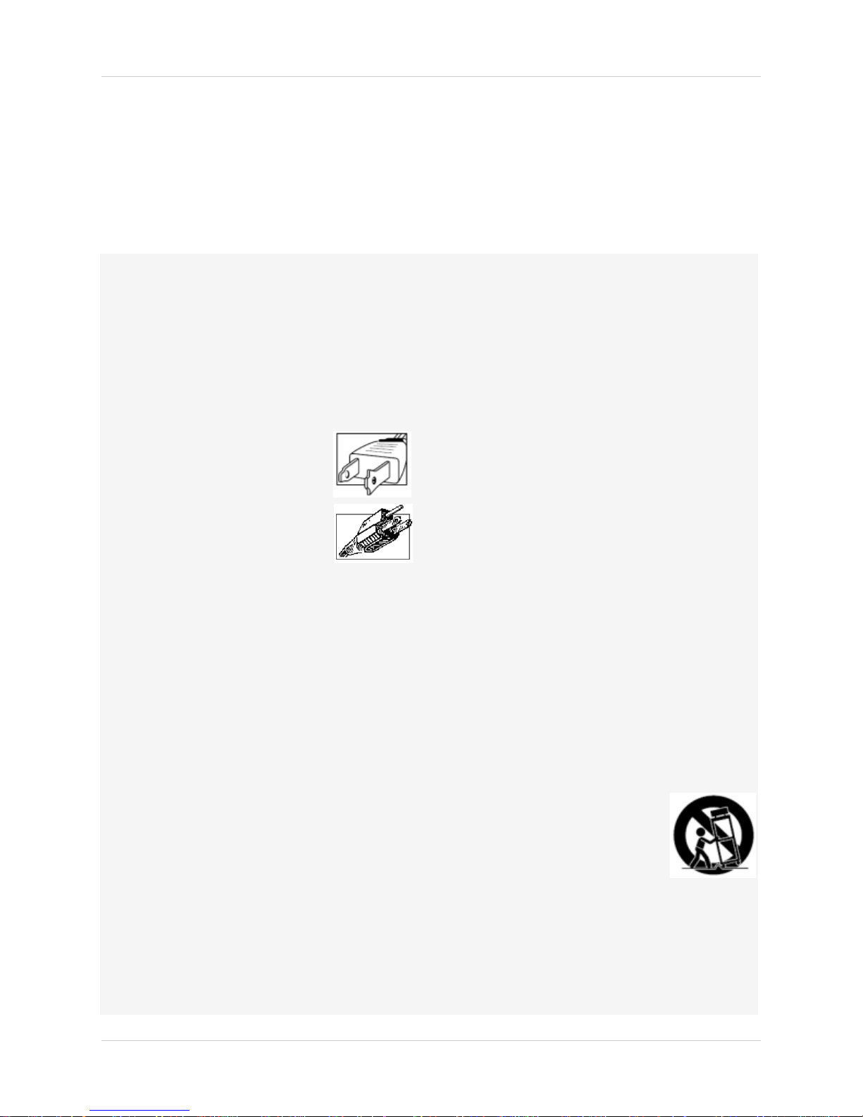
4. Polarization - Do not defeat the
safety purpose of the polarized or
grounding-type plug.
A polarized plug has two blades
with one wider than the other.
A grounding type plug has two
blades and a third grounding prong.
The wide blade or the third prong
are provided for your safety.
If the provided plug does not fit into your outlet,
consult an electrician for replacement of the
obsolete outlet.
5. Power Sources - This video product should be
operated only from the type of power source
indicated on the marking label. If you are not sure of
the type of power supply to your location, consult
your video dealer or local power company. For video
products intended to operate from battery power, or
other sources, refer to the operating instructions.
6. Overloading - Do not overload wall outlets of
extension cords as this can result in the risk of fire
or electric shock. Overloaded AC outlets, extension
cords, frayed power cords, damaged or cracked wire
insulation, and broken plugs are dangerous. They
may result in a shock or fire hazard. Periodically
examine the cord, and if its appearance indicates
damage or deteriorated insulation, have it replaced
by your service technician.
7. Power Cord Protection - Power supply cords should
be routed so that they are not likely to be walked on
or pinched by items placed upon or against them,
paying particular attention to cords at plugs,
convenience receptacles, and the point where they
exit from the video product.
8. Ventilation - Slots and openings in the case are
provided for ventilation to ensure reliable operation
of the video product and to protect it from
overheating. These openings must not be blocked or
covered. The openings should never be blocked by
placing the video equipment on a bed, sofa, rug, or
other similar surface. This video product should
never be placed near or over a radiator or heat
register. This video product should not be placed in a
built-in installation such as a bookcase or rack
unless proper ventilation is provided or the video
product manufacturer’s instructions have been
followed.
9. Attachments - Do not use attachments unless
recommended by the video product manufacturer as
they may cause a hazard.
10. Camera Extension Cables – Check the rating of
your extension cable(s) to verify compliance with
your local authority regulations prior to installation.
11. Water and Moisture - Do not use this video product
near water. For example, near a bath tub, wash
bowl, kitchen sink or laundry tub, in a wet
basement, near a swimming pool and the like.
Caution
operated equipment or accessories connected to
this unit should bear the UL listing mark of CSA
certification mark on the accessory itself and should
not be modified so as to defeat the safety features.
This will help avoid any potential hazard from
electrical shock or fire. If in doubt, contact qualified
service personnel.
12. Accessories - Do not place this
video equipment on an unstable
cart, stand, tripod, or table. The
video equipment may fall, causing
serious damage to the video
product. Use this video product
only with a cart, stand, tripod,
bracket, or table recommended by the
manufacturer or sold with the video product. Any
mounting of the product should follow the
manufacturer’s instructions and use a mounting
accessory recommended by the manufacturer.
: Maintain electrical safety. Powerline
ix
Page 14

Service
13. Servicing - Do not attempt to service this video
equipment yourself as opening or removing covers
may expose you to dangerous voltage or other
hazards. Refer all servicing to qualified service
personnel.
14. Conditions Requiring Service - Unplug this video
product from the wall outlet and refer servicing to
qualified service personnel under the following
conditions:
• When the power supply cord or plug is damaged.
• If liquid has been spilled or objects have fallen into
the video product.
• If the video product has been exposed to rain or
water.
• If the video product does not operate normally by
following the operating instructions. Adjust only
those controls that are covered by the operating
instructions. Improper adjustment of other controls
may result in damage and will often require
extensive work by a qualified technician to restore
the video product to its normal operation.
• If the video product has been dropped or the cabinet
has been damaged.
• When the video product exhibits a distinct change
in performance. This indicates a need for service.
Use
19. Cleaning - Unplug the video product from the wall
outlet before cleaning. Do not use liquid cleaners or
aerosol cleaners. Use a damp cloth for cleaning.
20. Product and Cart Combination - Video and cart
combination should be moved with care. Quick
stops, excessive force, and uneven surfaces may
cause the video product and car combination to
overturn.
21. Object and Liquid Entry - Never push objects for
any kind into this video product through openings as
they may touch dangerous voltage points or
“short-out” parts that could result in a fire or
electric shock. Never spill liquid of any kind on the
video product.
22. Lightning - For added protection for this video
product during a lightning storm, or when it is left
unattended and unused for long periods of time,
unplug it from the wall outlet and disconnect the
antenna or cable system. This will prevent damage
to the video product due to lightning and power line
surges.
15. Replacement Parts - When replacement parts are
required, have the service technician verify that the
replacements used have the same safety
characteristics as the original parts. Use of
replacements specified by the video product
manufacturer can prevent fire, electric shock or
other hazards.
16. Safety Check - Upon completion of any service or
repairs to this video product, ask the service
technician to perform safety checks recommended
by the manufacturer to determine that the video
product is in safe operating condition.
17. Wall or Ceiling Mounting - The cameras provided
with this system should be mounted to a wall or
ceiling only as instructed in this guide, using the
provided mounting brackets.
18. Heat - The product should be situated away from
heat sources such as radiators, heat registers,
stoves, or other products (including amplifiers) that
produce heat.
General Precautions
x
Page 15

General Precautions
FCC CLASS B NOTICE
NOTE
This equipment has been tested and found to comply with the limits for a Class B digital device, pursuant to
Part 15 of the FCC Rules. These limits are designed to provide reasonable protection against harmful
interference in a residential installation. This equipment generates, uses, and can radiate radio frequency
energy and, if not in-stalled and used in accordance with the instruction, may cause harmful interference to
radio communications.However, there is no guarantee that interference will not occur in a particular
installation. If this equipment does cause harmful interference to radio or television reception (which can be
determined by turning the equipment on and off), the user is encouraged to try to correct the interference by
one or more of the following measures:
• Reorient or relocate the receiving antenna
• Increase the separation between the equipment and receiver
• Connect the equipment into an outlet on a circuit different from that to which the receiver is connected.
• Consult the dealer or an experienced radio or television technician for assistance
www.lorextechnology.com
1. All warnings and instructions in this manual should be followed.
2. Remove the plug from the outlet before cleaning.
water dampened cloth for cleaning.
3. Do not use this unit in humid or wet places.
4. Keep enough space around the unit for ventilation. Slots and openings in the storage cabinet
should
not be blocked.
5. During lightning storms, or when the unit is not used for a long time, disconnect the power
suppl
y, antenna, and cables to protect the unit from electrical surge.
Do not use liquid aerosol detergents. Use a
This equipment has been certified and found to comply with the limits
regulated by FCC, EMC, and
LVD. Therefore, it is designated to provide reasonable protection against interference and will not
cause interference with other appliance usage.
However, it is imperative that the user follows the guidelines in this manual to avo
usage which may result in damage to the unit, electrical shock and fire hazard injury.
In order to improve the feature functions and quality
to change without notice from time to time.
of this product, the specifications are subject
id improper
xi
Page 16

1. Recording time may vary based on recording resolution & quality, lighting conditions and movement in the scene. Storage
calculator included on your CD.
2. Requires a high speed internet connection and UPNP (Universal Plug & Play) router - not included.
3. Apple MAC compatible using Safari Web browser for selectable single channel live viewing.
4. Always use discretion when installing video and/or audio surveillance equipment especially when there is perceived privacy.
Inquire regarding federal, state and/or local regulations applicable to the lawful installation of video and or audio recording
or surveillance. Party consent may be required.
†Instant Mobile Viewing on Blackberry™, iPhone™ or Windows Mobile™ 6.0 and above: selectable one channel live viewing. Mobile
phone data plan is required (not included). Router port-forwarding required. For the latest smart phone compatibility list check
www.lorextechnology.com Microsoft Windows™ 7, XP™, Vista™ are trademarks of Microsoft Corporation. iPhone is a trademark
of Apple Inc. Blackberry is a trade mark of Research In Motion Ltd. Other trademarks are the property of Lorex Technology Inc. We
reserve the right to change models, configurations or specifications without notice or liability. Product may not be exactly as
shown. Images are simulated.
Features
Digital Video Recorder Features
• H.264 compression supports D1 (704x480) resolution video recording (1)
• Pentaplex operation - View, Record, Playback, Back up & Remotely control the system
simultaneously
• DVI (with VGA converter) & BNC outputs for display on PC or TV monitor
• 24/7 100% duty cycle hard drive pre-installed, expandable up to 2TB
• Back-up critical images to USB media: flash drive, external HDD
• GUI with mouse navigation for easy set-up and programming
Connectivity
• LOREX Instant Mobile Viewing on iPhone™, Blackberry™, Windows® Mobile and other
compatible 3G smart phones†
• Exclusive LOREX Easy Connect Internet Set-up Wizard (2)
• PC (Microsoft Windows™ 7/Vista/XP compatible) using Internet Explorer® browser
• Apple Mac compatible (3) using the Safari browser for selectable single channel live viewing
• Free LOREX DDNS (Dynamic Domain Name Service) for advanced remote connectivity at all
times
• Instant email alerts
xii
Page 17

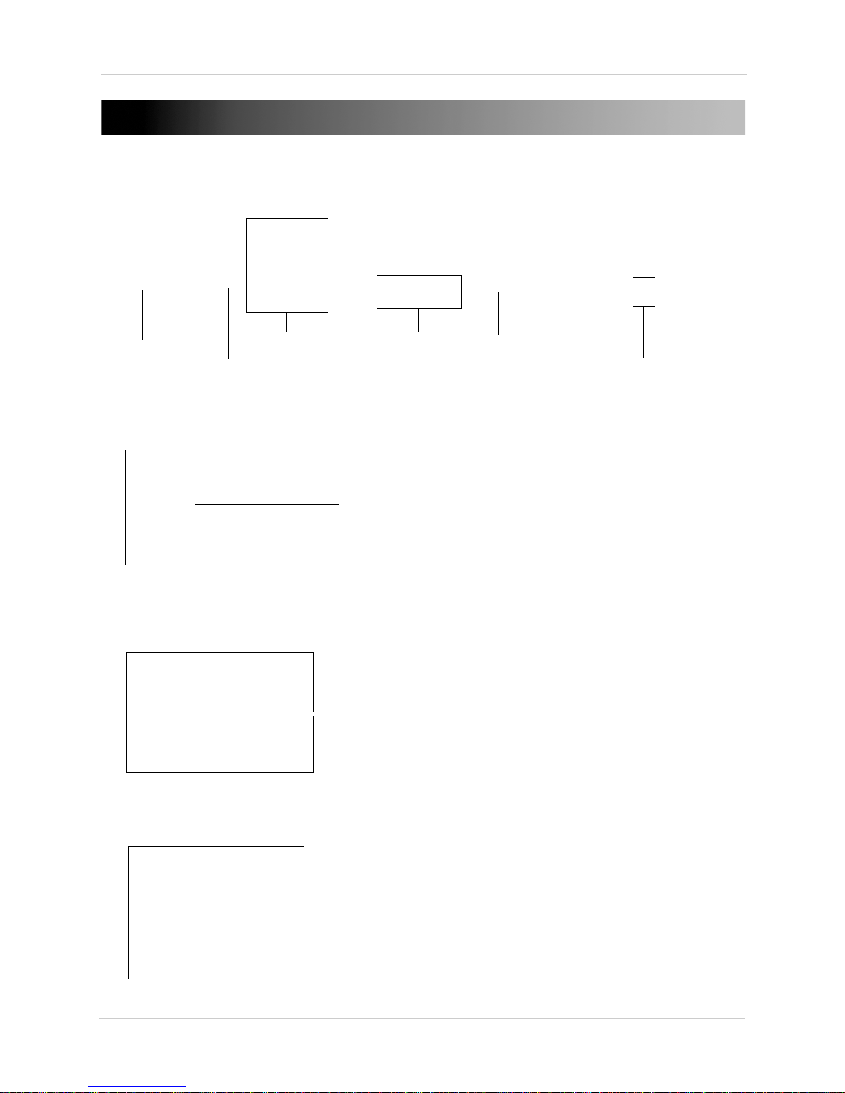
GETTING STARTED
DIGITAL VIDEO RECORDER
POWER CABLE
AND POWER ADAPTER
QUICK START GUIDE,
MANUAL, (ELECTRONIC MANUAL CD)
REMOTE
CONTROL
DVI TO VGA ADAPTER
MOUSE
ETHERNET CABLE
The system comes with the following components:
HARD DRIVE SIZE, NUMBER OF CHANNELS, AND CAMERA CONFIGURATION MAY VARY
BY MODEL. PLEASE REFER TO YOUR PACKAGE FOR SPECIFIC CONTENT DETAILS.
CHECK YOUR PACKAGE TO CONFIRM THAT YOU HAVE RECEIVED THE COMPLETE SYSTEM,
INCLUDING ALL COMPONENTS SHOWN ABOVE.
1
Page 18
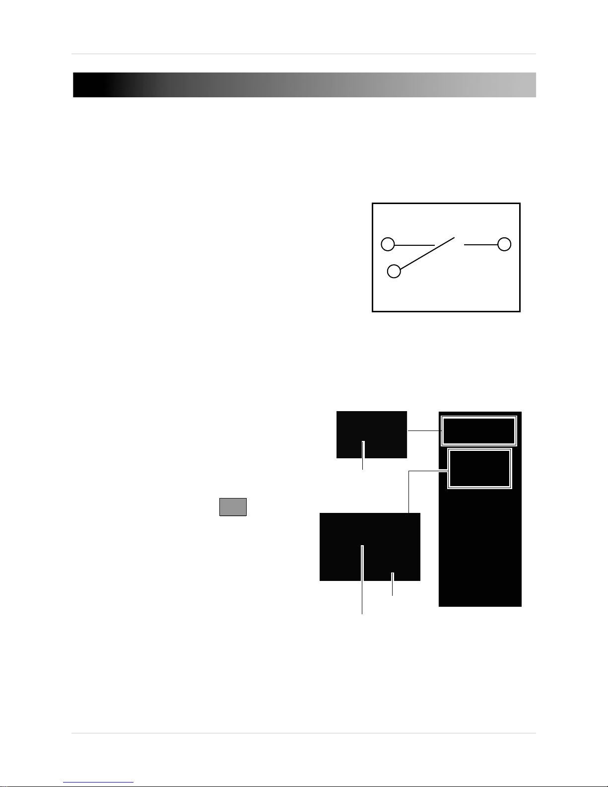
BASIC SETUP
BNC Camera connection
USB Mouse connection
Ethernet Port
DVI Connection
Power Connection
PAL/NTSC Switch
BNC Port
USB Port
Ethernet Port
1. CONNECT THE BNC CAMERAS
• Connect the BNC cameras to the BNC ports on the rear panel of the system.
2. CONNECT THE MOUSE
• Connect a USB mouse to the USB port on the rear panel of the system.
3. CONNECT THE ETHERNET CABLE
• Connect the ethernet cable to the ethernet port on the rear panel of the system.
2
Page 19

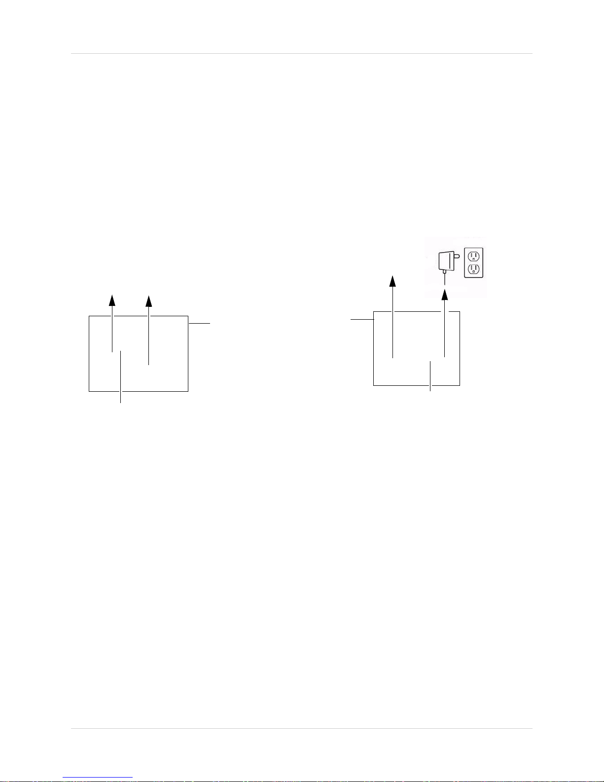
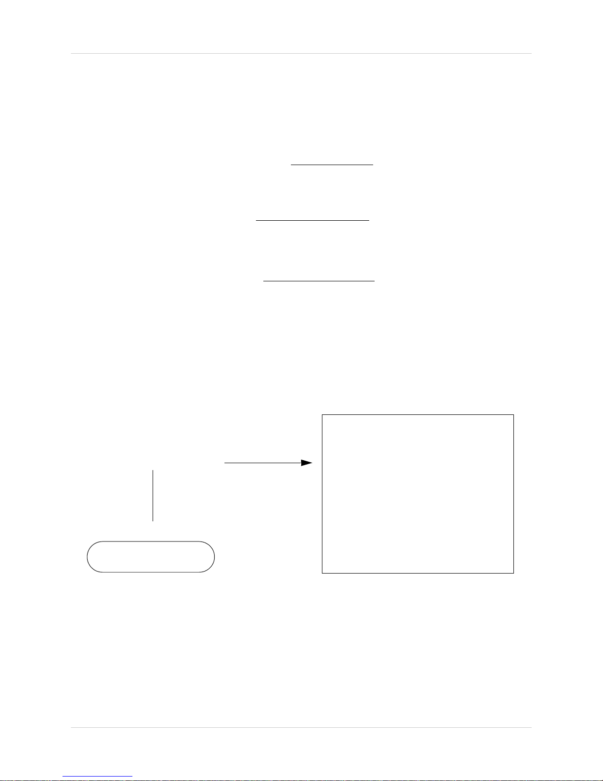
4. CONNECT A DVI DISPLAY
DVI Port
DC12V Port
The Default System Password is: 1234
• Connect a DVI display to the DVI port. Use a DVI to VGA converter for VGA displays.
5. CONNECT THE POWER ADAPTER
• Connect the power adapter to the system. Connect the end of the power adapter to a wall
socket or a surge protector.
6. VERIFY CAMERA IMAGE
• Verify camera video quality before mounting the cameras to a permanent location.
• If your region uses PAL output, use the PAL/NTSC switch on the rear panel of the system to
change your region’s display mode.
7. SET THE TIME
• Set the system time for accurate video time stamps. Videos with inacurate times may not be
valid as surveillance evidence.
• For details on setting the time, see “Setting the Time” on page 25.
3
Page 20

Connecting The Cameras
Top t hrea d
(Ceiling mount, Wall mount)
Bottom thread
(Table mount)
Secure to cam era thre ad
*Camera model not be exactly as shown.
Figure 1.0 Camera stand installation.
Table Mount
Wall Mount Ceiling Mount
Figure 1.1 Camera mounting options. Camera model not be exactly as shown.
CONNECTING THE CAMERAS
Before you mount the cameras, test to ensure the cameras have no problems. Plan where you will
route the wiring for the camera, and where you will aim the camera.
Installation Tips
1. Mount the camera where the lenses are away from direct and intense sunlight.
2. Plan your cable wiring so that it does not int
3. Ensure that the camera wiring is not exposed, or easily cut.
4. Adjust the camera angle so that it covers an area with high traffic.
5. In "high-risk" locations, have multiple cameras point in the same area. This provides camera
r
edundancy if a camera malfunctions, or if a vandal attempts to damage the camera.
6. Mount the camera in an area that is visible, but out of reach.
erfere with power lines or telephone lines.
CAMERA STAND INSTALLATION
1. Mount the camera stand to the desired mounting surface. Choose a firm mounting surface.
NOTE: If you wish to mount the camera stand to drywall, it is recommended to use drywall plugs
(not included).
2. Attach the camera to the stand.
NOTE: There are two connection points for certain cameras. Secure the stand to the top thread
for wall-mounts or ceiling mounts. Secure the stand to the bottom thread for table-mounts or
wall mounts.
4
Page 21
Connecting BNC Cameras
Male power connector
BNC Extension cable
Female power connector
Figure 1.2 BNC camera connectivity diagram.
Digital Video Recorder
To install BNC cameras to your system:
1. Connect the male power connector on the BNC extension cable to the female power
c
onnector on the camera.
• Connect the BNC connector to the camera.
2. Connect the female power connector on the BNC extension cable to the power adapter.
• Connect the BNC connector to the BNC port on the system.
3. Plug the power adapter to a power outlet.
Connecting and Removing BNC cables
BNC (Bayonet Nut Connector) is a special connector that locks on to the system port, and cannot
be accidently removed.
To connect or remove a BNC connector:
• Push the BNC connector firmly into the BNC port and simultaneously twist the connector
• To remove a BNC connector from a BNC port, push and simultaneously twist the connector
ockwise to tighten.
cl
counter-clockwise to loosen the BNC connector.
5
Page 22
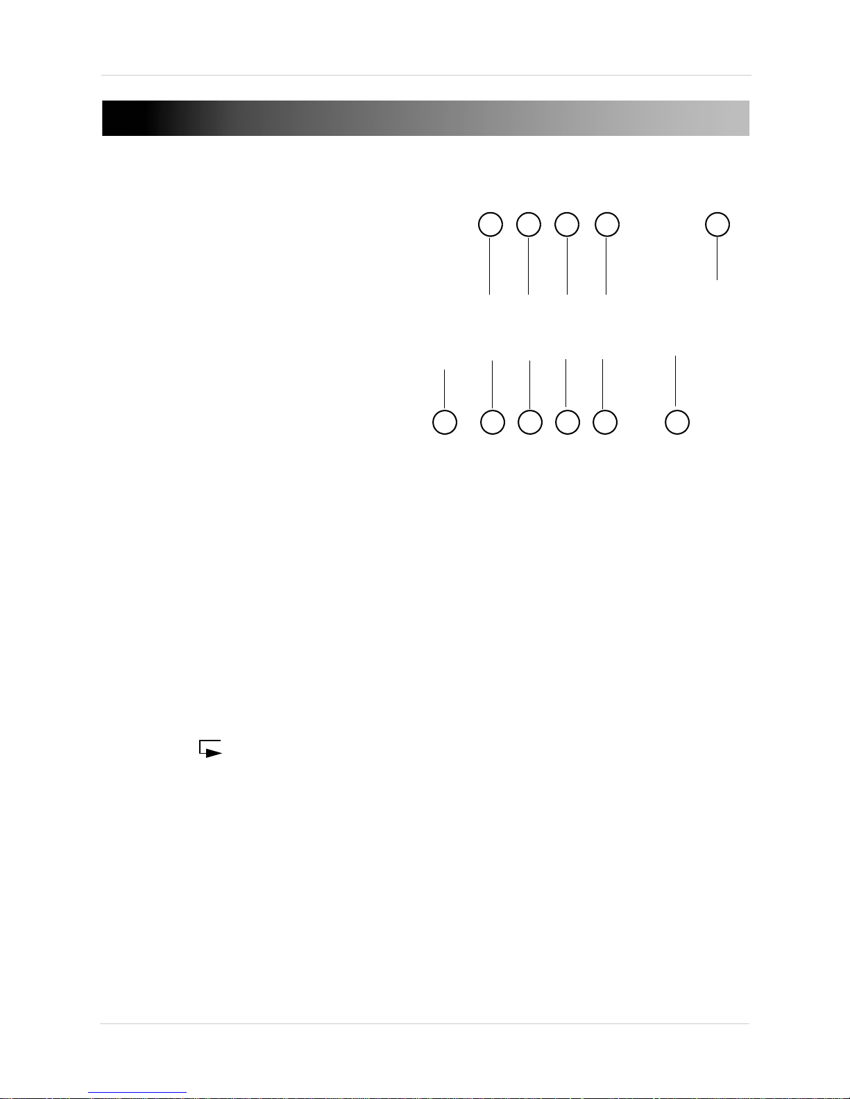
FRONT PANEL
Figure 1.3 Front system panel.
1 2 3 4 5
6 7 8 9
10
11
1. Power: Shuts down the system.
2. Di
splay: Switches viewing mode between single-channel, quad mode, and sequence mode.
3. Sear
4. Me
5. Ent
6. USB P
7. RE
8. PLA
9. FA
ch: Opens the video search menu.
nu: Opens the quick menu.
er: Confirms selections in the menu.
ort: Reads USB memory keys for firmware upgrades.
WIND: During video playback, press rewind to view video in reverse playback (-1x,- 2x, -4x,
-8x, -16x, -32x and -64x).
Y/PAUSE: During video playback, press pause/play to stop or resume video playback.
ST FORWARD: During video playback, press fast forward to view video in forward playback
(1x, 2x, 4x, 8x, 16x, 32x and 64x).
10. RE
11. Di
6
TURN ( ): Exits the screen selection.
rection Pad: Use the direction pad to navigate the system menus.
Page 23
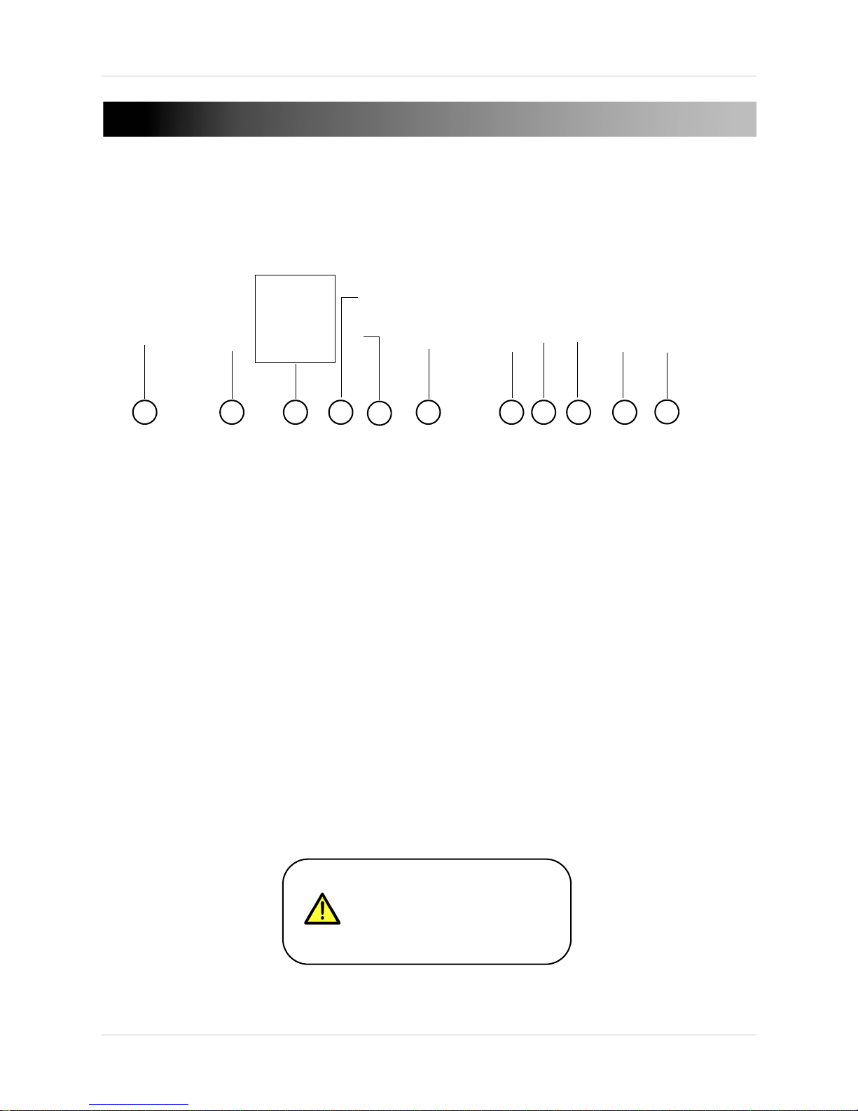
REAR PANEL
Figure 1.4 Rear system panel (4-channel model shown).
1 2 3 4
5
6 7 8 9
10
11
Keep the exaust fan on the side
panel clear for proper ventilation.
Inadequate ventilation causes the
unit to overheat.
Rear Panel
1. DC 12V: Port for 12V power cable (included).
ETHERNET PORT: Connect an Ethernet cable to connect the system to a router or switch (not
2.
included).
VIDEO IN : Camera input ports for BNC cameras; (4-channel configuration shown).
3.
MONITOR: BNC output (top) to connect the system to a secondary monitor or DVR.
4.
SPOT OUT: Spot Monitor output (bottom). Spot monitor only displays a single channel of a camera and
5.
does not display system menus.
DVI: DVI output to connect the system to a DVI monitor (not included). Use a DVI to VGA adapter (not
6.
included) to connect a VGA monitor to the system.
USB port: Connect a USB mouse to navigate the system.
7.
8. AUDIO IN: Connect one audio input device (i.e. amplafied microphone, not included).
AUDIO OUT: Connect a single audio output (i.e. speakers, not included).
9.
ALARM Block: Connect external alarm, motion devices , or a PTZ (Pan Tilt Zoom) camera to the
10.
system (not included).
PAL / NTSC : Switch between PAL and NTSC video output.
11.
7
Page 24
Control Devices
4
5
6
7
2
Fig ure 2 .0 R emot e Co ntro l.
1
3
CONTROL DEVICES
Remote Control
1. POWER: Press to power the system ON/OFF
(password required).
2.
System Mode buttons:
MODE: N/A.
•
SETUP: Opens the DVR Setup menu.
•
ID: Press to select the DVR ID (to control
•
multiple DVRs with a single remote).
F1: Opens the System Information window.
•
F2: N/A.
•
F3: N/A
•
REC START: Starts panic recording.
•
About the ID button: Changes the ID for the
remote control to match the System ID (if
changed). Exit to the main viewing screen, and
press the
ID window. Press the number keys on the remote
to assign the remote an ID and then press the
ENTER key.
3.
Navigation / Menu buttons:
ID button twice to open the REMOTE
Audio buttons:
6.
• + / - : Not in use.
• AUDIO: Not in use.
Mode buttons:
7.
P/T/Z (Pan, Tilt, Zoom): Press to open the
•
PTZ control menu (on channels with PTZ
cameras only, not included).
KEYLOCK: Press to open the Log Off window.
•
SEQUENCE: Press to start/stop Auto
•
Sequence mode.
ZOOM: N/A
•
8.
ARCHIVE: Press to open the Archive menu.
ENTER : Press to confirm menu options/
•
selections.
RETURN : Press to cancel/deselect
•
previous screen.
• S: Press to move cursor up; increase values in
certain menu options.
• T: Press to move cursor down; decrease values
in certain menu options.
• W: Press to move cursor left.
• X: Press to move cursor right.
: Press to pause playback.
•
: Press to increase reverse playback speed
•
1X, 2X, 4X, 8X,16X, 32X, and 64X.
: Press to increase forward playback speed
•
1X, 2X, 4X, 8X, 16X, 32X, and 64X.
MENU/ SEARCH / DISPLAY buttons:
4.
• MENU: Opens the Quick Menu.
• SEARCH: Opens the system search menu.
• DISPLAY: Switches between single channel and
4-channel view.
Channel buttons: Press to view individual
5.
channels in full-screen; press to input
passwords; when entering camera titles, press
for alpha-numeric characters.
8
Page 25
SYSTEM NAVIGATION
1 2
3
Figure 2.1Mouse buttons
F1 button
Figure 2.2 Accessing system information using the remote.
Enter button
Return button
Mouse Control
The mouse is an optional control device for the system.
To connect a USB mouse:
• Connect a USB mouse to the USB port on the front panel
NOTE: If using a PS/2 mouse (not included), a PS/2-to-USB
adapter (not included) is required
1. Left-Button: While in a split-screen display mode,
double-click an individual channel to view it in full-screen;
double-click again to return to the split-screen display mode.
While navigating menus, click to select a menu option.
2. Right
3. Scr
-Button: Right-click anywhere on the screen to open the
Quick Menu.
oll-Wheel: N/A
System Navigation
Remote Control Navigation
When navigating the menus using the remote
control, perform the following:
• Press the
on-screen cursor
• Press the ENTER button (
option
• Press the RETURN button (
the option
Quickly Access System Information
• To access vital system information such as
your system’s MAC address and IP address,
press F1 on your remote.
STWX buttons to move the
) to select an
) to de-select
9
Page 26

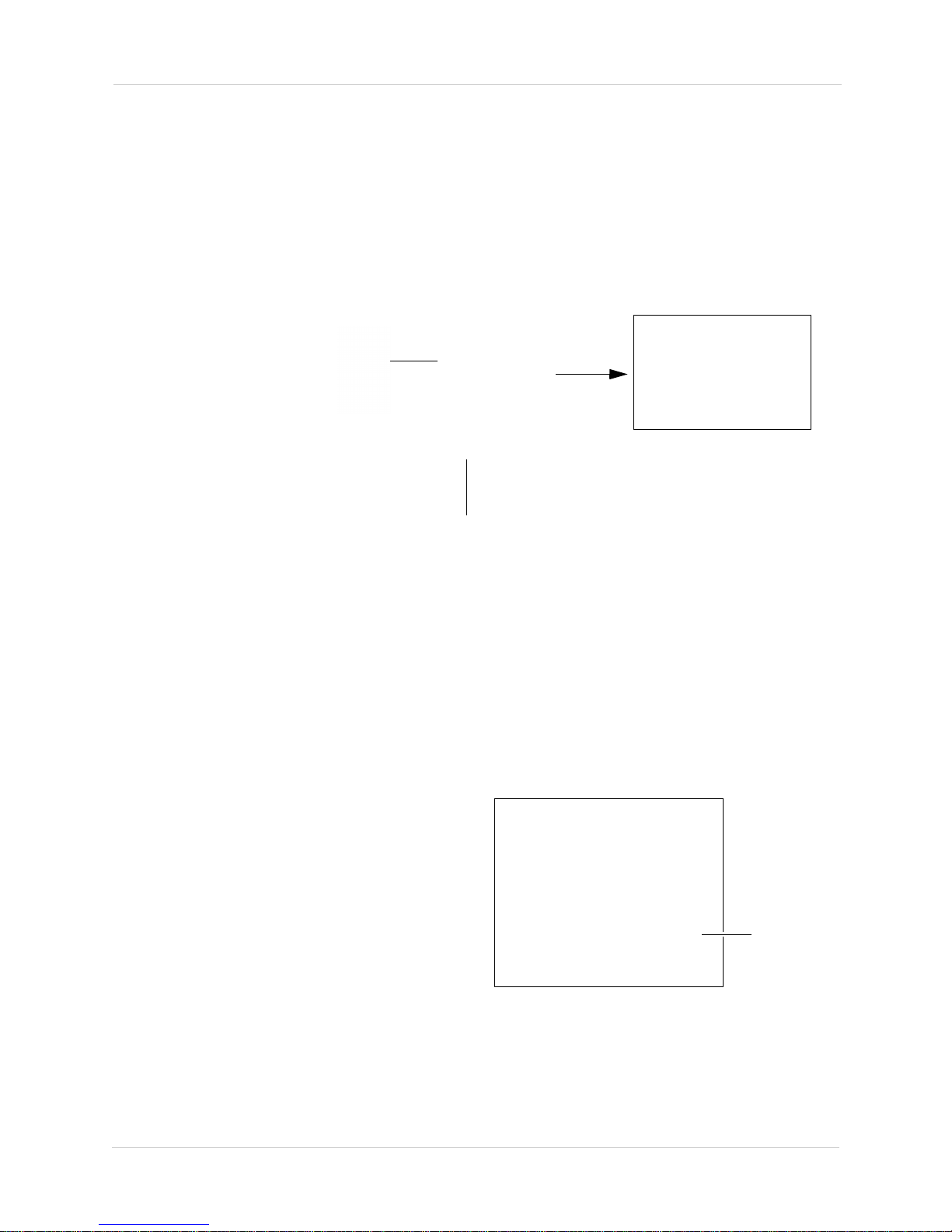
Using the System
Right-click to open the Quick Menu.
Click SHUTDOWN.
Figure 3.0 Powering off the system.
It is recommended to plug your system into a backup power
supply (not included). Backup power supplies provide power
to your system and cameras in case of an electrical outtage.
USING THE SYSTEM
Once the system is properly connected, you may power on your system and log in.
Powering on/off The System
To power on the system:
1. Connect the DC12V power adapter to the rear panel of the system.
2. Press the PO
• The system powers on.
• W
ait for the system to boot up into the main screen.
To power off the system:
1. Press the PO
• A confirmation window opens.
2. Click YE
or
WER button on the front panel.
WER button on the front panel of the system.
S to shut down the system.
1. Right-click anywhere on the screen.
• The Quick Menu opens.
2. Click SHUTDO
WN.
• A confirmation window opens.
3. Click YE
S to shut down the system.
10
Page 27
Using the System
Live video channel
Status bar
Figure 3.1 Main viewing window. (4-channel model shown).
Login window
Double-click to open Virtual Keyboard
Default System Password:
1234
Figure 3.2 Entering your password into the Virtual Keyboard.
Logging In To The System
When you power on the system, it performs a hard drive and system integrity check. Wait for the
system to boot into the main viewing window before operating.
NOTE: By default, the system login window is disabled. To enable password login to your system,
see “Enabling and Disabling The System Password” on page 51.
To log in to the system (if password is enabled):
1. Double-click on the blank PASSWORD field in the Login window.
• A Virtual Keyboard window opens.
2. Enter 12
• The Virtual Keyboard closes, and the Login window re-appears.
3. Click OK in th
34 and then click the OK button.
e Login window.
11
Page 28
Using the System
Click LOG OFF
Figure 3.3 Logging off the system.
Log Off window
Caps Lock
button
Figure 3.4 Virtual Keyboard.
Logging Out Of The System
To log out of the system:
1. Exit to the main viewing window if necessary.
2. Right-click anywhere on the screen.
• The Quick Menu window opens.
3. Click LO
• The LOG OFF window opens.
GOFF.
4. Click (Log Off).
• A Log off prompt window opens.
5. Click YE
The system disables the Quick Menu options when the system is logged
S to log off the system.
out. You can continue
viewing video streams when the system is logged out.
NOTE: Panic Recording, Sequence and PTZ remains enabled even when the system is logged out.
USING THE VIRTUAL KEYBOARD
Use the Virtual Keyboard to enter passwords and
camera titles on the system.
To use the Virtual Keyboard:
1. Select any desired letter, number, or
ch
aracter.
2. Press ENTER
panel to confirm your selection; or click the
ENTER button.
NOTE: Click the "A"( ) button to shift
between upper and lowercase letters.
on the remote control or front
12
Page 29
Using the System
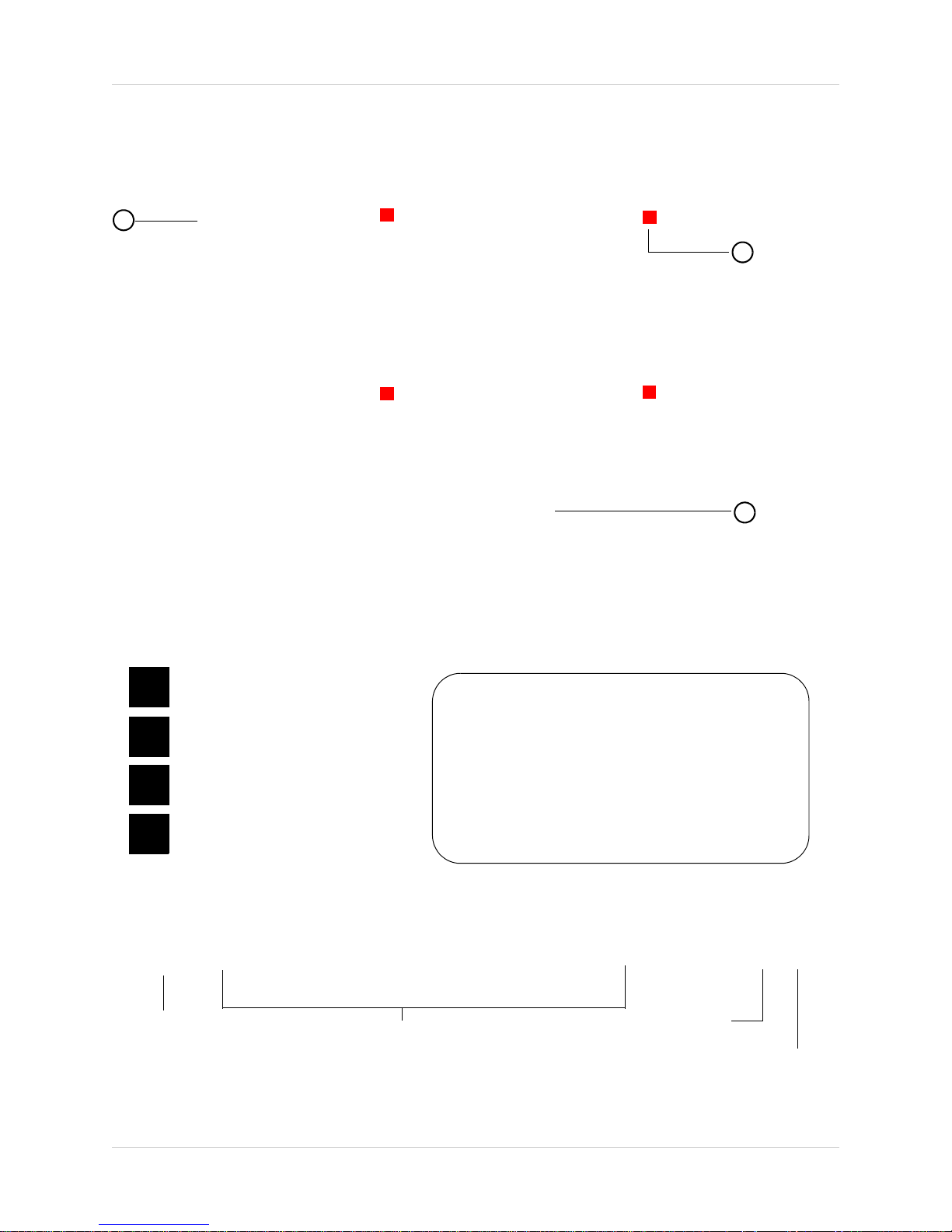
Figure 3.5 Main viewing mode (4-channel model shown).
1
2
3
C
C
C
C
C
M
P
Continuous Recording
Motion Recording
Panic Recording
Alarm Recording
A
Figure 3.6 Recording Status types.
• Continuous Recording records 24 hours a
day.
•
Motion Recording records only when the
camera detects movement.
•
Panic Recording marks the video as a
’Panic’ event, allowing for easy searchability.
•
Alarm Recording marks the video when an
alarm is triggered.
1. Network Icon
2. Year/ Month/ Date/ Time
3. Hard drive
recording mode
4. Hard Drive Storage Indicator
Figure 3.7 System status bar.
On-Screen Display
By default, the system launches with a live, quad-screen view also called the Main Viewing mode:
1. Channel Title: Displays the channel number or title.
2. Rec
3.
ording Status: Different icons represent different recording modes: Continuous, Motion, Panic, and
Alarm.
Status Bar: Displays system time, date, and recording status.
13
Page 30
Using the System
Full-Screen
Quad
Auto Sequence
Figure 3.8 Display Viewing modes.
Figure 3.9 Enabling Auto Sequence.
Sequence button
The Status Bar gives you an overview status of the system.
1. Netw
ork Status: Shows the status of the network connection. Blue=network connection is
connected; Grey=network connection is not connected.
2. Date
3. HDD Status: "O
& Time: Shows the current date and time on the system.
W" indicates disk overwrite is enabled. For details, see “Disk Manage” on
page 56.
4. H
ard Drive Storage Indicator: Displays the percentage of the hard drive space used for video
storage.
Changing Display Modes
The system has different display modes as well as an Auto Sequence mode.
To change display modes:
• Press the DISPL
AY button repeatedly until you reach the desired display mode.
USING AUTO SEQUENCE
Auto Sequence allows you to view channels in full-screen in an automatic sequence. In sequence
mode, the screen cycles channels through the channels one channel at a time in full screen view.
To start Auto Sequence:
1. Press the DISPL
appears near the top of the screen.
or
1. Right-click anywhere on the screen in the main
viewing window.
• The Quick Menu opens.
2. Click SEQUEN
NOTE: You must exit from system setup menus
before enabling Auto Sequence.
To customize the duration of the sequence, see
“Monitor Tab” on page 38.
AY button on the front control panel until the (Auto Sequence) icon
CE.
14
Page 31

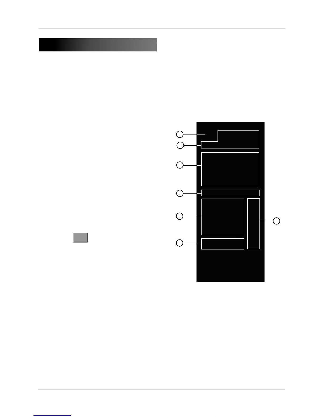
Quick Menu
Quick Menu
Figure 4.0 Opening Quick Menu in the main viewing window.
Configure system Display, Camera,
Sound, and system settings.
Configure recording type
(continuous, motion, alarm),
and camera resolution settings.
Mark a live event as a "Panic"
recording. This allows you to search
and watch "Panic" events only.
View live video in sequence mode.
Opens the PTZ (Pan, Tilt, Zoom)
menu for PTZ enabled cameras
(not included).
Search for archived videos by time,
or search a video by event.
B ac ku p v i de os t o a n e xt er n al de vi c e.
Locks the system.
Power off the system.
Figure 4.1 Understanding the Quick Menu.
Understanding the Quick Menu
The Quick Menu gives you an overview of all the
available settings on your DVR.
To open Quick Menu:
1. Right-click anywhere on the screen in the
main vie
NOTE: If you are configuring the system, you
cannot open Quick Menu.
or
wing window.
1. Press the MENU butt
on on the front panel.
15
Page 32

Using the System
Event Calendar
Yea r
Selection cursor
Time
Play button
Timeline Slider
Month
Figure 4.2 Search window layout.
Figure 4.3 Event Calendar.
Selection Cursor
Searching For Video
You can search for videos by time, or search videos by event.
To open the Search menu:
1. Right-click anywhere in the main vie
2. Click the button
• The Search window opens.
wing window to open the Quick Menu.
SEARCHING FOR VIDEO BY TIME
Searching for video by time is useful if you know the approximate date and time an event occurred.
To search for an event by time:
1. Right-click anywhere in the main
vie
wing window to open the Quick
Menu.
2. Click the button.
• The Search window opens.
3. In the event calendar, select the Year
and Month using the sel
4. Click on the date the event occurred.
• The date highlights with an orange box.
16
ection cursors.
Page 33

5. Double-click on the Hour, Minute and Second the event occurred to enter the time.
Time selection
Double-click to adjust value
Number window opens
Figure 4.4 Adjusting video search time.
Selection Cursor
Drag Timeline Slider to adjust the time
Figure 4.5 Adjusting the time using the Timeline Slider
• A number window opens each time you double-click on the Hour, Minute and Second.
• Ent
er the desired value and click the OK button to save your settings.
OR
• The video playback screen opens.
• Drag the Timeline Slider to adjust the
time.
OR
• Click the hour/minute and then use
the selection cursor to adjust the
values.
6.Click to view the
video.
17
Page 34

Using the System
Figure 4.6 Search by Event window.
Select date and
time range
Select
channel(s)
Select event type
Click Start to begin
search
Click to view the next
page of the log
Double-click date or time to begin video playback
Figure 4.7 Starting video playback.
SEARCHING FOR VIDEO BY EVENT
Searching for video by event allows you to sort video events by category. For example, if you want
to view all the events where the camera detected movement, you can search by motion.
To search a video by event:
1. Right-click anywhere in the main vie
2. Click the button.
• The Search window opens.
3. Click the SEARCH BY
EVENT tab.
• The Search By Event window opens.
wing window to open the Quick Menu.
4. Under SEARCH BY TIME, select the date and time range the event occurred.
• Click on the Hour, Month, Year, Time, and then use the
values.
OR
• Double-click on the Hour, Month, Year, time to use the number window to enter the value.
5. Select the channel you wish to search under (Channels 1~4)
6. Under SEARCH BY EVENT, select the type of event you wish to search for.
• Search by: Alarm, Motion, Continuous, Other
7. Click to begin video search.
• The event types populate in the Log.
8. Double-click on the date or time of
18
ST(selection cursors) to adjust the
.
the event to begin playback.
Page 35

Using the System
1 2 3
4 5
6
7
8
9
10
Figure 4.8 Video playback controls.
VIDEO PLAYBACK CONTROLS
The video playback controls allows you to navigate through the video. The playback window opens
after you START or PLAY in the Search menu.
1. Channel Lis
2. Inc
3. Re
rease Reverse Playback Speed: Speed up reverse playback.
verse Playback: Watch video backward.
4. Play/P
5. F
orward playback: Watch video forward in normal speed (1x).
6. Incr
7. Ex
ease Forward Playback Speed: Fast forward video playback.
it video playback: Exits the playback screen and returns to main system view.
8. Date: Display
9. Vi
deo Timeline: Displays the current time of the event being played.
10. Vid
eo Playback Speed Indicator: Displays forward and reverse playback speed.
t: Click to adjust playback view (single-channel view, or Quad view).
ause: Click once to play. Click again to pause.
ed as Year, Month, Date by default.
19
Page 36

Archiving VIdeo
Figure 5.0 Archiving menu.
Select date and time
range.
Select channel(s) to
back up.
Select whether you
want the backup to
include audio or a
system log.
Select backup mode.
Select backup
device.
Click START to
begin backup.
Preview button
ARCHIVING VIDEO
The system allows you to archive your videos onto external media such as a USB memory stick,
or an external hard drive.
Hardware required:
• A blank USB memory key (2 Gigabytes and up recommended) or an external USB hard drive
To back up video onto an external device:
1. Insert a blank USB memory key or USB hard drive int
system.
2. Right-click anywhere in the main vie
wing window to open the Quick Menu.
3. Click .
• The Archiving window opens.
o the USB port on the front panel of the
4. Beside the FROM and TO fields, se
• Click on the desired value and use the buttons to adjust the values.
OR
• Double-click on the Year, Month, Date, Time to use the number window to enter the value.
5. Beside CH
1, CH2, CH3, CH4, select the channels you wish to back up.
6. Beside the Include Audio and Include Log ch
include audio or a system log.
7. Beside DEV
8. Beside MODE, select ERASING &
the video contents.
• Select BURNING to back up the video onto the USB memory key.
9. Click ST
20
ICE, select the back up device using the buttons.
ART to begin video back up.
lect the Year, Month, Date, Time you wish to back up.
eckbox, select whether you want the back up to
BURNING to format the USB memory key before backing up
Page 37

Archiving VIdeo
Click "Open folder to view files"
Figure 5.1 AutoPlay window in Windows Vista/7.
USB drive contents
Figure 5.2 USB device directory.
Viewing Archived Video
Once you have backed up video onto your USB memory key or USB hard drive, you can view the
video on your PC. The system includes a proprietary video player called Backup Player. Use
Backup Player to play video archived video from your USB device.
Prerequisites:
• A free USB port
To view archived video from your USB memory key / USB hard drive:
1. Insert the USB memory key or USB hard drive into the computer’s USB port.
2. Browse your system for your USB device.
• On Windo
ws XP: Double-click My Computer and then double-click the Removable Disk
directory (or the name of your USB hard drive).
• On Windows Vista/7: An autoplay window pops-up. Click "Open folder to view files" to browse
your USB device
3. Double-click the folder named AR
CHIVE _XXXXXX_XXXXXX (where X is the date, year, time)
in the USB memory key/hard drive directory.
21
Page 38

4. Double-click on setup.exe to install the video codec.
USB Folder Contents:
• bplayer (Backup Player): Proprietary video player.
• setup.exe: Video codec required to watch the video.
• arch_info.txt: A technical log of the archived video.
• AVI video file: Shown as "Ch01_XXXX .....", where CH01 is
dependant on what channel you chose to back up.
• Log file: Displays what time the archive was made, and by
which user.
Figure 5.3 Backup Player contents.
Main video window
Browse button
Screen Capture
button
Video Playback Controls
Print Button
Figure 5.4 Backup Player interface.
• Follow the on-screen instructions and install the video codec.
5. Double-click on bp
layer.exe to start the video player.
• The Backup Player opens.
22
Page 39

Archiving VIdeo
Video Playback Controls
Speed Slider
Browse button
Playback Time
Figure 5.5 Backup Player Controls.
Print button
P
Figure 5.6 Panic Recording.
Panic Recording
Indicator
6. Click the Browse button on the bottom-right hand corner of the screen (Figure 5.4).
• An "Open" window appears.
7. Double-click on the video file.
• A Watermark notification window opens.
8. Click YE
NOTE: By default, the "Open" window automatically opens in the same directory where the video
S to begin video playback.
file is located. If this is not the case, manually browse for your video file.
Backup Player Playback Controls
• In the Playback Time display, you can manually enter the time you wish to jump to.
• Use the Print button to print a screen capture of the current video being played. Stop the video
before pressing the Print button.
• Click the Screen Capture button on the top-left corner of the player to print a BMP (bitmap)
or JPG (Jpeg) image.
Panic Recording
Panic recording tags the video as a "Panic" recording, and records video with the highest quality
settings. Tagging a video as "Panic" allows you to search for the video as a Panic recording.
To start Panic recording using the mouse:
1. Right-click anywhere on in the main viewing
window t
2. Click RE
top-right corner of the channel changes to P
(Panic).
3. To exit Panic recording, right-click to open the
quick men
recording.
o open the quick menu.
C START. The recording icon on the
u and click REC START to stop panic
23
Page 40

Archiving VIdeo
REC START (Panic) button
Figure 5.7 Triggering panic recording using the remote.
Panic eventPanic event
Figure 5.8 Search menu populating a panic event in the log list.
To start Panic recording using the remote:
1. Press the RE
C START button in viewing
mode (must exit from all system menus).
2. Press the REC ST
ART button again to stop
panic recording.
Searching for Panic Recording Video
Once you have "bookmarked" panic events,
you can search your video archive for "panic"
video events.
To search for Panic Recording Video:
1. Right-click anywhere in the main vie
2. Click the button.
• The Search window opens.
3. Click the SEARCH BY
EVENT tab.
• The Search By Event window opens.
wing window to open the Quick Menu.
4. Double-click on the field that shows a "panic" recording to begin playback.
24
Page 41

Setting the Time
Figure 6.0 System Setup Menu.
SYSTEM button
ATTE NTIO N
If the saved time is earlier
than the current time on
the system, you will be
warned that overlapped
data will be erased.
Click YES to accept the
changes. Please allow a
few moments for the
overlapped video data to
be deleted.
SETTING THE TIME
Set the time before recording. Inaccurate time stamps on videos reduces the effectiveness of the
surveillance video as evidence. The time can be synchronized to a Network Time Server, or can be
set manually.
To set the date and time:
1. Right-click anywhere on in the main viewing windo
2. Click .
• The System Setup window opens.
w to open the quick menu.
3. Click (System).
• The System window opens.
4. Beside D
mm/ss) and adjust the values using the buttons.
OR
• Double-click the values to open the number window to
input the values.
5. Beside DA
the date format.
6. Click APPL
Automatic Time Synchronization
• Click the button to synchronize your time with a time server. You must connect
the system to the internet to synchronize your system time.
Daylight Savings Time
• To enable daylight savings, under D.S.T, select ON using the button and then click APPLY.
ATE TIME, click on the time (yyyy/mm/dd; hh/
TE FORMAT, use the button to adjust
Y to save your settings.
25
Page 42

Recording
C
Figure 6.1 Continuous Recording.
Figure 6.2 Motion Recording icons (inactive and active)
M
RECORDING
By default, the system is set to record continuously at startup from any connected cameras. It is
highly recommended to keep continuous recording on at all times.
The system can perform Continuous Recording, Motion
Recording. You can set a customized daily or weekly recording schedule using these recording
modes. For details, see “Configuring Recording Settings” on page 28.
Continuous Recording
By default, all camera channels are enabled with continuous recording. During Continuous
Recording, the letter "C" appears in the top-right corner of each channel.
Recording, Alarm Recording, and Panic
Motion Recording
The system will only record when motion is detected by a camera. When Motion Recording is
enabled, an "M" in the top-right corner of every channel indicates the system is recording. You can
set the pre and post recording time in the Recording Operations menu.
For details, see
“Configuring Recording Modes (Simple Recording)” on page 29.
26
Page 43

Recording
Figure 6.3 Panic Recording icon (top-right corner)
P
Alarm Recording
When an alarm input is triggered, the system continues to record, but can apply unique recording
parameters that you can set in the Alarm menu. You can also set the system to activate an alarm
output. For example, if a window sensor (not included) connected to the alarm input block on the
rear panel is triggered, the system begins alarm recording. The system simultaneously activates
an external siren (not included) connected to the alarm output block on the rear panel.
For details, see “Alarm Input” on page 53.
Panic Recording
Press the REC START button on the remote control or right-click in the main viewing window, and
click on REC START. Panic Recording features the highest quality recording parameters available
on the system. A "P" appears in the top-right corner during Panic Recording. For details on
enabling Panic recording, see “Panic Recording” on page 27.
Recording Audio
The system can record one channel of audio. You must have an audio enabled camera or
self-powered microphone connected to the system to use this function (not included). You can
enable/disable audio recording in the Continuous/Motion Recording menu. For details, see
“Sound” on page 43.
27
Page 44

Configuring Recording Settings
Quick Menu
Figure 7.0 Opening the Quick Menu.
Record Setup Button
Record Setup Menu
Figure 7.1 Opening the Record Setup window.
CONFIGURING RECORDING SETTINGS
To access Record Setup menu:
1. Right-click anywhere in the main viewing window.
• The quick-menu opens.
2. Click .
• The Record Setup menu opens.
ADJUSTING PRE & POST EVENT RECORDING TIME
After an event occurs in the system, such as a motion event, you can configure how many seconds
before and after the system continues to record.
To configure Pre Event and Post Event recording time:
1. Right-click anywhere in the main viewing window.
• The quick-menu opens.
2. Click .
• The Record Setup menu opens.
28
Page 45

Configuring Recording Settings
Select SIMPLE (default)
Figure 7.2 Enabling Simple Recording mode.
Simple Recording Tab
3. Beside PRE EVENT RECORDING TIME, use the buttons to adjust the pre-event
recording time in seconds (1~5 seconds).
4. Beside POST EVENT
RECORDING TIME, use the buttons to adjust the post-event
recording time in seconds (5~180 seconds).
5. Click to save your settings.
CONFIGURING RECORDING MODES (SIMPLE RECORDING)
You can customize what time the system records in Contiuous, Motion or Alarm mode.
• Continuous recording mode sets the system to record in a loop, regardless if the camera
c
aptures any movement.
• Motion recording only records when the camera detects movement.
• Alarm recording marks the video as an "Alarm" event when an external sensor (not included)
connected to the alarm block in the system is triggered.
To configure the type of recording mode during a particular time:
Enable Simple Recording Mode
1. Right-click anywhere in the main viewing window.
• The quick-menu opens.
2. Click .
3. Beside RE
4. Click to save your settings.
• The Record Setup menu opens.
CORDING MODE, select SIMPLE (default) using the buttons.
29
Page 46

Configuring Recording Settings
Figure 7.3 Record Setup - Simple Recoring mode.
Recording Schedule
Recording quality
Screen Resolution
Video Frame Rate
Figure 7.4 Configuring recording schedule duration.
Drag the mouse cursor to select recording duration
Configure Recording Quality, Screen Resolution and Frame Rate
1. Click the SIMPLE RECORDING tab on the left.
• The Simple Recording window opens.
2. Beside RE
CORD QUALITY, select the video recording quality (Low, Standard, High, Highest)
using the buttons .
3. Beside RE
CORD SIZE, select the video resolution that the camera records at using the
buttons.
• Recording resolutions: 352 x 240 at 30 FPS / 704 x 240 at 15 FPS / 704 x 480 at 7 FPS /
4. Beside FPS, sel
NOTE: The recording settings applied in steps 2 to 4 are global and apply to all of the cameras.
ect the video frame rate of the cameras using the buttons.
To configure each camera individually, you must switch the recording setup to Advanced
Recording. For details, see “Configuring Recording Modes (Advanced Recording)” on page 31.
Configure Recording Schedule
1. Drag the mouse cursor in the Recording Schedule to select the duration you wish to enable a
recording type.
30
Page 47

Configuring Recording Settings
Figure 7.5 Recording pop-up menu.
Figure 7.6 Enabling Simple Recording mode.
Select ADVANCED
• A Recording Type pop-up opens.
2.Select the type of recording you want to
enable (Continuous, Motion, Alarm).
3.Click OK
to save your settings.
Scheduling Tips
• Customize the recording schedule
according to foot traffic in a particular area.
For example, if you monitor a vacant parking
lot with light traffic, consider setting Motion
recording. This reduces video storage
space, and enables the camera to only
record when there is movement.
• Customize the recording schedule of when it is busiest. For example, you may only want
Continuous recording during the day to monitor a high traffic area.
CONFIGURING RECORDING MODES (ADVANCED RECORDING)
Advanced Recording allows you to customize how the camera records depending on the time of
day. For example, you can have Camera 1 record at a higher resolution during the day, and record
at a lower resolution at night. You can also configure the type of recording each camera will record
at depending on the time of day. You can schedule the Advanced Recording mode to Daily or
Weekly.
Daily recording settings apply the same recording settings to all 7 days
of the week. Weekly
recording settings are customizable for each day of the week.
To configure Advanced Recording mode:
Enable Advanced Recording
1. Right-click anywhere in the main
viewing window.
• The quick-menu opens.
2. Click .
• The Record Setup menu opens.
3. Beside RECORDING MO
ADVANCED using the
buttons.
DE, select
4. Click to save your
settings.
• The SCHEDULE MODE option is now enabled. For details on configuring Weekly Schedule
mode, see “Customizing Recording Type (Weekly mode)” on page 35.
31
Page 48

• The ADVANCED RECORDING tab appears on the left.
Advanced
Recording Tab
Customizable to Weekly or Daily
Figure 7.7 Enabling Advanced Recording.
Figure 7.8 Customizing recording quality.
Recording Timeline
5. Click the ADVANCED RECORDING tab on the left.
• The Advanced Recording Menu opens.
Customize Recording Quality
You can customize the recording quality depending on the hour of the day. For example, you may
want your cameras to record at the highest quality between 9:00am and 4:00pm, and reduce the
video quality after 4:00pm to conserve storage space.
To customize video recording quality:
1. Drag your mouse cursor across the Recording Timeline (Figure X) and select the desired hour
y
ou wish to customize the recording quality.
32
Page 49

• A Recording Quality window opens.
Recording Quality window
Figure 7.9 Configuring recording quality.
Frame rate indicator
Configuring Recording Settings
2. For each camera, customize the following using the buttons:
• Size: Cus
tomize the video resolution
• FPS (Frames Per Second): Adjust the video frame rate. Higher frame rates yield smoother
video, but increase file sizes.
NOTE: The Frame rate indicator displays the remaining frames that you can allocate to the
cameras.
ality: Adjust video quality. Higher video quality yields higher quality video images, but
• Qu
increase file sizes.
• Audio: Enable or disable audio (audio capable cameras only).
• Alarm: Enable or Disable external alarm devices (not included).
3. Click OK t
o save your settings. Repeat as necessary for different times.
33
Page 50

Configuring Recording Settings
Camera Schedule
Figure 7.10 Customizing camera recording type (Daily mode).
Figure 7.11 Recording pop-up menu.
Customizing Recording Type (Daily mode)
After you customize each camera’s recording quality, you must assign each camera’s recording
type. For example, you may want Camera 1 to record with Continuous recording between 9:00 am
until 11:00 am. Then you may want Camera 1 to record with Motion recording between 11:30 am
until 3:00 pm.
To customize the camera’s recording type in Daily mode:
1. Click the AC
• The Activation tab opens.
TIVATION tab.
2. Drag the mouse cursor in the Camera Schedule to select the time range you want a
p
articular recording event to take place.
• A Recording pop-up window opens.
3. Select the recording type (Continuous, Motion, Alarm) and then click OK.
4. Click to save your settings.
5. Repeat the process as needed.
34
Page 51

Customizing Recording Type (Weekly mode)
Camera Schedule
Figure 7.12 Customizing camera recording type (Weekly mode).
Date selection box
Activation Tab
Figure 7.13 Recording pop-up menu.
To customize the camera’s recording type in Weekly mode:
1. Click the RECORDING OPE
RATIONS tab on the left.
Configuring Recording Settings
2. Beside RE
3. Beside SC
CORDING MODE, select ADVANCED using the buttons.
HEDULE MODE, select WEEKLY using the buttons.
4. Click to save your settings.
5. Click the AD
6. Click the AC
VANCED RECORDING tab on the left.
TIVATION tab.
• The Activation tab opens.
7. In the Date selection box, select the day you wish to apply the settings to.
8. Drag the mouse cursor in the Camera Schedule to select the time range you want a
• A Recording pop-up window opens.
9. Select the recording type (Continuous, Motion, Alarm) and then click OK.
10. Click to save your settings.
11. Repeat the process as needed.
p
articular recording event to take place.
35
Page 52

Configuring Recording Settings
Figure 7.14 Configuring Manual Recording settings.
Panic Recording tab
Frame rate indicator
CONFIGURING PANIC RECORDING
Panic recording allows the camera to switch into "panic" mode, and mark the video as a panic
event. When a camera is in panic mode, it automatically adjusts its recording parameters, and
records at a higher video quality. You can customize the recording quality of your camera in panic
recording to suit your preferences.
To configure Manual Recording settings:
1. Right-click anywhere in the main viewing window.
• The quick-menu opens.
2. Click .
• The Record Setup menu opens.
3. Click the P
4. The Panic Recording menu opens.
ANIC RECORDING tab on the left.
5. For each camera, customize the following using the buttons:
6. Click APPL
36
• Size: Cus
tomize the video resolution
• FPS (Frames Per Second): Adjust the video frame rate. Higher frame rates yield smoother
video, but increase file sizes.
NOTE: The Frame rate indicator displays the remaining frames that you can allocate to the
cameras.
• Qu
ality: Adjust video quality. Higher video quality yields higher quality video images, but
increase file sizes.
• Audio: Enable or disable audio in panic recording mode (audio capable cameras only, not
included).
• Panic Recording Time: Adjust the maximum duration of panic recording.
Y to save your settings.
Page 53

Configuring System Setup
System Setup button
Figure 8.0 Activating quick menu.
Figure 8.1 System Setup menu.
CONFIGURING SYSTEM SETUP
System setup allows you to configure the system’s Display, Camera, Sound, System, Sensor,
Network and Hard Drive recording settings.
To open the System Setup menu:
1. Right-click anywhere in the main viewing window.
• The quick-menu opens.
2. Click .
• The System Setup menu opens.
System Setup Overview
• Display: Configure system OSD (On-screen display), language, and display options.
• Camera: Configure camera color adjustments, PTZ Camera settings, and motion sensor
settings.
• Sound: Configure system buzzer and live audio from audio-enabled cameras (not included).
• System: Configure Network, User management
• Event/Sensor: Configure external alarm sensor devices (not included) and system notification
settings.
• Disk Manage: Configure hard drive recording and formatting settings.
37
Page 54

Configuring System Setup
Figure 9.0 Display OSD setting window.
OSD tab
Figure 9.1 Display Monitor setting window.
Monitor tab
DISPLAY
The Display tab configures the system OSD
(On-screen display), language and display
options.
To open the Display menu:
1. Right-click anywhere in the main viewing
ndow.
wi
• The quick-menu opens.
2. Click .
• The System Setup menu opens.
3. Click DISPL
• The Display menu opens.
AY.
• EVENT ICON: Toggle ON/OFF to enable or
disable the recording icon of the system on
the top-right corner of the channel.
• BORDER: Toggle ON/OFF to enable or
disable the black border around the
channels.
• Beside LANGUAGE, use the buttons
to change the system language.
2. Click APPL
Y to save your settings.
MONITOR TAB
Changing Motion , Alarm Pop-up, Spot
and Sequence settings:
1. Click The MONITOR tab on the left.
• The Monitor tab opens.
OSD TAB
Changing OSD (On Screen Display)
options:
1. Configure the following using the
buttons:
• ST
ATUS BAR: Toggle ON/OFF to enable or
disable the system status bar.
• CAMERA TITLE: Toggle ON/OFF to enable
or disable the camera title on the top-left
corner of the channel.
38
1. Configure the following using the
buttons:
• SEQUENCE DWELL: Adjust the duration of
how long the a channel remains on screen
in Sequence mode.
• SPOT OUT DWELL: Adjust the duration of
how long the channel remains on screen in
Spot Out mode.
• DEINTERLACE MODE: Deinterlace mode
increases image sharpness. Turn on/off to
enable or disable.
• ALARM POP-UP MODE: If Alarm Pop-Up
mode is enabled, the channel
Page 55

automatically displays in full screen when
an alarm event is triggered.
• ALARM POP-UP DWELL: Adjust the
duration that the Alarm-pop-up channel
remains on screen.
• MOTION POP-UP MODE: If Motion
Pop-Up-Mode is enabled, the channel with
motion detected displays in full screen.
• MOTION POP-UP DWELL: Adjust the
duration the Alarm-Pop-Up window
remains on screen.
2. Click APPLY to save your settings.
Configuring System Setup
39
Page 56

Configuring System Setup
Figure 10.0 Camera Setup menu.
Camera Title tab
Figure 10.1 Color Setup menu.
Color Setup tab
Channel number
Close button
Figure 10.2 Color Configuration bar.
CAMERA
Use the Camera menu to configure
camera title, color, PTZ and motion
settings.
To open the Camera menu:
1. Right-click anywhere in the main viewing
wi
ndow.
• The quick-menu opens.
2. Click .
• The System Setup menu opens.
3. Click CA
• The Camera setup window opens.
MERA.
• If ON, the channel will appear blacked out
on-scr
een, but the system will actually be
recording.
2. Click APPL
Y to save your settings.
COLOR SETUP TAB
Adjusting Camera Brightness and Color
To adjust camera color settings:
1. Click the COL
• The Color Setup tab opens.
OR SETUP tab on the left.
CAMERA TITLE TAB
Changing the Camera Title
To change a camera title:
1. Under TITLE, double-click the field to open
the Vir
2. Enter a title for the camera (up to eleven
a
The Virtual Keyboard closes.
3. Click APPL
Enabling Covert Mode
To enable/disable covert camera:
1. Under COVERT, click to turn ON/OFF
covert mode.
tual Keyboard.
lphanumeric characters), and click OK.
Y to save your settings.
2. Double-click on the value you wish to
adjus
t in the desired channel.
• The channel opens in full-screen with a
olor-configuration bar near the bottom of
c
the window.
3. Click to adjust the Brightness,
Contrast, Tint and Color Values.
4. Beside , click to
change the camera channel.
5. Click the Close button ( ) to exit and
save your settings.
40
Page 57

Configuring System Setup
Figure 10.3 PTZ Setup menu.
PTZ Property button
PTZ Setup tab
Figure 10.4 PTZ property window.
PTZ SETUP TAB
PTZ Setup
Use the PTZ Setup menu to configure any
connected PTZ cameras (not included).
NOTE: Make sure your PTZ camera is
properly connected to the system prior to
configuring PTZ options. Please refer to
your PTZ camera’s instruction manual to
determine the correct settings for your PTZ
camera.
To configure PTZ settings:
1. Click the PTZ SETUP t
• The PTZ Setup tab opens.
ab on the left.
• Baud Rate choices: 96
00 (default),19200,
38400, 57600, 115200, 230400, 1200, 2400
or 4800,
5. Click to open the PTZ property
window.
6. In the PTZ Property window, click to
configure the following PTZ properties:
• Channel Number
• Aut
o Focus
• Auto Iris
• P/T (pan / tilt) speed
7. Click OK t
o save your settings.
2. Under ADDRESS, select a channel and
click ; select the PTZ address
~255).
(1
3. Under PROTOCOL, select the PTZ protocol
using the button.
• Protocol types:
PelcoD, PelcoP
MESA-DOME, D-MAX, Ganz PT ,FastraxII
2, SCC_641, SCC_643a, Spd_3300, Multix,
MRX_1000, Panisonic WV-CS850,
Panisonic WV-csr-604, PTC-400c,
PTC-200, LPT-A100L
4. Under BAUD RATE, click to select
desired baud rate.
41
Page 58

Configuring System Setup
Figure 10.5 Motion Sensor menu
Motion Sensor tab
Figure 10.6 Motion Grid.
Figure 10.7 Grid selection menu.
MOTION SENSOR TAB
Configuring Motion Sensor Sensitivity
Use the Motion Sensor menu to configure
motion detection settings for each camera.
To configure motion settings:
1. Click the MO
• The Motion Sensor tab opens.
TION SENSOR tab on the left.
• A grid selection menu opens.
6. Click SA
VE & EXIT to save your changes
OR
• Click SELECT ALL to select the entire grid
and then click SAVE & EXIT.
• Click DESELECT ALL to clear the grid and
then click SAVE & EXIT.
7. Repeat for the remaining channels.
2. Under SENSITIVITY, click to adjust
the sensitivity level for the desired
annel.
ch
• The higher the number, the greater the
sensi
tivity.
3. Click the ARE
A button.
• The Motion Area Grid opens.
4. Drag the mouse cursor to select the area
you want to monitor for motion.
that
CAMERA MODE TAB
The camera mode tab allows you to enable/
disable Camera Line Lock. Select ON or OFF to
enable or disable camera line lock.
NOTE: Camera Line Lock is an optional
setting for line-lock cameras. You do not
have to enable Camera Line Lock for your
camera to view or record.
5. Right-click anywhere on the screen.
42
Page 59

Configuring System Setup
Figure 11.0 Audio Menu
Audio tab
Figure 11.1 Buzzer Menu.
Buzzer tab
SOUND
Configure live audio, network
audio, and buzzer settings.
NOTE: Audio-capable cameras or
self-powered microphones (not included)
must be connected to the system in order
to use listen-in audio (live audio
monitoring).
Use the audio menu to configure live audio and
network audio sett
To open the Sound menu:
1. Right-click anywhere in the main viewing
wi
ndow.
• The quick-menu opens.
2. Click .
• The System Setup menu opens.
3. Click SOUND.
• The Sound setup window opens.
ings.
NOTE: You must use audio-capable cameras
(not included) for live audio to transmit from
the camera to the system.
2. Beside NETWORK AUDIO TX
(tr
ansmit),click to select ON to
enable network audio transmission.
3. Beside NETWORK AUDIO RX (receive),
sel
ect ON to enable the system to receive
audio from the cameras.
4. Click APPL
Y to save your settings.
BUZZER TAB
Disabling System ’Beeps’
To disable the system ’beeps’:
1. Click the BUZZE
• The Buzzer menu opens.
R tab on the left.
NOTE: Network audio will consume more
bandwidth and may affect the transmission
of the video signal. Enable or disable
network audio based on your network
settings.
AUDIO TAB
Enabling System Network Audio
1. Beside LIVE AUDIO, click to select
o enable live audio.
ON t
2. Under KEYPAD, click to select OFF.
3. Under REMOTE CONTROL, click to
select OFF.
4. Click APPL
Y to save your settings.
43
Page 60

Configuring System Setup
Figure 12.0 System menu.
Date/Time tab
Figure 12.1 Number window.
SYSTEM
Configure date and time, system
management settings, and control
device options.
To open the System menu:
1. Right-click anywhere in the main viewing
ndow.
wi
• The quick-menu opens.
2. Click .
• The System Setup menu opens.
3. Click SY
• The System setup window opens.
STEM.
2. Enter the desired value and then click OK
t
o save your settings.
Configuring system Date format and
24 HR vs 12HR time notation
To configure the system date and time format:
1. Beside DATE FORMAT, click to adjust
the date and time format (ie. Year, Month
e VS. Month, Date, Year).
Dat
2. Beside TIME FORMAT, click to select
24 hour or 12 hour time notation.
3. Click APPL
Y to save your settings.
Configuring Time Server
A time server allows the system to sync itself
with a specified server time. This ensures that
your system always has an accurate time.
To change the default time server:
1. Under NETWORK TIME SERVER SETUP,
doubl
e-click on the field below.
• A virtual keyboard opens.
2. Enter a new time server address.
3. Click OK t
4. Click the SY
• A success message appears.
5. Click APPL
o save your settings.
NC button.
Y to save your settings.
DATE/TIME TAB
Configuring system Date and Time
By default, once you open the system menu,
the DATE/TIME menu opens.
To configure the system date and time:
1. Beside DATE TIME, double-click on the
numeric v
• A number window opens.
44
alues (Year, month, date).
Enabling/Disabling Daylight Savings Time
To enable/disable daylight savings time (DST):
1. Under D.S.T,click to select ON/OFF
to enable or disable daylight savings time.
2. Click APPL
Y to save your settings.
Adjusting System Time Zone
To manually adjust the system time zone:
1. Under TIME ZONE SETUP,click to
adjust the system time zone.
2. Click APPL
Y to save your settings.
Page 61

Configuring System Setup
Figure 13.0 System Network tab.
Network tab
Double-click blank field
Figure 13.2 Configuring DDNS settings.
Figure 13.3 DDNS Setup window.
NETWORK TAB
To open the Network tab:
1. Click the NETW
• The network configuration window opens.
Enabling DDNS & DHCP
You must enable DDNS and and DHCP for
remote connectivity.
ORK tab on the left.
• A DDNS Setup window opens.
2. Beside DOMAIN NA
ME, double-click the
blank field.
• The Virtual Keyboard opens.
3. Enter the name of your DDNS address (i.e.
omsmith).
t
NOTE: You do not have to enter the entire
domain name in the DOMAIN NAME field.
For example, if your DDNS address is
tomsmith.lorexddns.net, you only have to
enter tomsmith.
To enable DDNS & DHCP:
1. Select the DHCP or DD
2. Click APPL
Y to save your settings.
NS checkbox.
Configuring DDNS Settings
After you have set up your DDNS account, you
must enter your DDNS address into the
system.
Prerequisites: Create a Lorex
For details, see “Setting Up DDNS Service” on
page 106.
To configure DDNS settings in your system:
1. Double-click the field beside DD
SERVER.
DDNS account.
NS
4. Beside USER ID, doubl
e-click the blank
field.
• The Virtual Keyboard opens.
5. Enter your DDNS l
ogin name created
during the DDNS account creation
process.
6. Click OK t
7. Beside PA
o save your settings.
SSWORD, double-click the blank
field.
• The Virtual Keyboard opens.
8. Enter the DD
NS password that you created
during the DDNS account creation
process.
9. Click OK t
NOTE: Your DDNS information is sent to your
o save your settings.
e-mail address when you create a DDNS
account. For details, see “Setting Up DDNS
Service” on page 106.
After you have entered the required DDNS
information,
click the DDNS STATUS button. A
success message appears if DDNS is running
properly.
45
Page 62

Configuring System Setup
Figure 13.4 Auto port forwarding.
Auto port forward buttonAuto port forward button
Double-click field
Mail tab
Figure 13.5 Mail tab.
Auto Port Forwarding
The LH600 series DVR features a built in
Auto-Port Forwarding function. This allows
you to port forward your UPnP router without
router configuration.
To port forward a port in your router:
1. Beside RTSP SERVER
the field.
• A Number window opens.
2. Enter the desired port number (by default,
port 55
3. Click OK t
4).
o save your settings
4. Beside RTSP SERVER PORT,click the
AUT
O button.
• A success message appears.
5. Beside WEB SERVER PORT, double-click
the field.
• A Number window opens.
6. Enter the desired port number (by default,
port 80)
7. Click OK t
o save your settings.
8. Beside WEB SERVER PORT, click the
AUT
O button.
• A success message appears.
PORT, double-click
Configuring System Transmission speed
The system transmission speed determines
how fast data transmits from the ethernet
port. By default, the system is set to 8 Mbps
transmission speed.
To configure the system transmission speed:
1. Beside MAX
TX SPEED, click to
adjust the maximum data transmission
speed.
2. Click APPL
Y to save your settings.
MAIL TAB
The Mail tab allows you to configure the
system to send e-mail notifications when a
system detects motion, or when an alarm
event triggers.
• For details, see “Appendix D: Enabling
E-Mail Notific
Prerequisites: Enable e-mail
and enter in an email address into the system
in the USER MANAGEMENT tab.
To open the Mail tab:
1. Click the MA
• The Mail configuration window opens.
ations” on page 123.
notifications,
IL tab on the left.
If you do not receive a success message:
• Double check that you have entered the
c
orrect system user name, password, and
DDNS address (enter your sub-domain
name only.)
• Use the Lorex DDNS Auto Port Forwarding
Wizard. For details, see “Lorex Auto Port
Forwarding Wizard” on page 99.
46
Configuring the E-mail Server
By default, the system uses the Lorex email
server to send notification e-mails.
Notification e-mails allow the system to send
Page 63

Configuring System Setup
De-select Default Server
Figure 13.6 Configuring the e-mail server.
User Management tab
Figure 13.7 User management tab.
you a message when an event occurrs (i.e. a
motion event).
To use the Lorex e-mail server
1. Select the checkbox beside DEF
:
AULT
SERVER (default).
NOTE: The SERVER, PORT, SECURITY,
USER, PASSWORD fields gray-out if
DEFAULT is selected.
2. Beside TEST
-EMAIL, click the PRESS
button.
• An email will be sent to your email address
ered under the USER MANAGEMENT
ent
tab.
3. Click APPL
Y to save your settings.
To configure the e-mail server using custom
settings
1. De-select the check box beside DEF
:
AULT
SERVER.
• The SERVER, PORT, SECURITY, USER,
P
ASSWORD fields can now be edited.
5. Enter the port number (specified by the
e-mail ser
6. Click OK t
ver).
o save your settings.
Enter your E-mail User name and Password
1. Beside USER, double-click the blank field.
• The Virtual Keyboard opens.
2. Enter your e-mail user name.
3. Click OK t
o save your settings.
Test your E-mail Account
Beside TEST E-MAIL, click the PRESS button
to verify that the system can properly connect
to your e-mail server.
Configuring Your System To Send
Notification E-Mails
To configure your system to send notification
e-mails, see “Appendix D: Enabling E-Mail
Notifications” on page 123.
Enter your E-mail Server & Port Information
1. Double-click on the blank field beside
SERVER.
• The Virtual Keyboard opens.
2. Enter the e-mail server name using the
Virtual Ke
3. Click OK t
yboard.
o save your settings.
4. Double-click the field beside PORT.
• The Number window opens.
USER MANAGEMENT TAB
The user management tab allows you to add,
remove and edit users who log in to the
system.
To open the User Management tab:
1. Click the US
left.
• The User Management window opens.
ER MANAGEMENT tab on the
47
Page 64

Configuring System Setup
Figure 13.8 Edit window.
Figure 13.9 Enabling email notifications.
Figure 13.10 Configuring Password Expiry duration.
Figure 13.11 Adding new users.
Configuring Email Notification Settings
To configure email notification settings:
1. Under USER ID, double-click the user you
wish t
o modify (ADMIN, USER or
MANAGER).
• The Edit window opens.
2. Double-click the blank field beside
E-MAIL.
• The Virtual Keyboard opens.
3. Enter the desired email you wish to receive
ation emails.
notific
4. Click OK t
o save your settings.
Configuring Password Expiry Duration
You can configure the system to refresh its
password list by enabling the Password Expiry
feature. This ensures that the system
password changes every few months.
To configure the system’s Password Expiry
Duration:
1. Beside PASSWORD EXPIRY, click to
select the duration of when you would like
the pas
• Select from 1 MONTH, 2 MONTHS, 4
MONTHS, 6 MONTHS, 12
• Click APPLY to save your settings.
sword to expire.
MONTHS or OFF.
5. Beside E-MAIL NOTIFICATION, click
to select ON.
6. Click OK t
NOTE: Ensure the EMAIL checkbox is
o save your settings.
selected.
Adding New Users
To add new users to the system:
1. Click the ADD
the window.
• The Add window opens.
button near the bottom of
48
Page 65

Configuring System Setup
System Management tab
Figure 13.12 System Management window
Figure 13.13 System Information window.
2. Configure the following:
• USER ID: Ent
er in the desired user name
by double-clicking the blank field beside
USER ID.
• PASSWORD: Enter in the desired user
password by double-clicking the blank field
beside PASSWORD.
• GROUP ID: Select the type of user account
you wish to create (MANAGER or USER).
• E-MAIL: Enter the e-mail address
associated with the account. This will be
the e-mail account that receives e-mail
notifications.
• E-MAIL NOTIFICATION: Select ON to
enable e-mail notifications for the account
• Click OK and then click APPLY to save your
settings.
SYSTEM MANAGEMENT TAB
The System Management tab allows you to
upgrade the system firmware, restore system
factory defaults, and view vital system
information.
To open the System Management tab:
1. Click the S
the left.
• The System Management window opens.
YSTEM MANAGEMENT tab on
Viewing System Information
• To view system information, click the
PRESS button beside SYSTEM
INFORMATION.
Changing The System Name
• To change the system name, double-click
the field beside SYSTEM NAME. Use the
Virtual Keyboard to enter the desired
system name (up to 15 characters).
Upgrading The System Firmware
Firmware updates enhance system stability
and performance.
Prerequisites:
Download the latest firmware from
www.lorextechnology.com and then extract the
file onto your USB flash drive.
To update the system firmware:
1. Insert the USB flash drive with the latest
firmwar
2. Beside F/W UPDATE, click the PRES
e into the USB port of the system.
S
button.
• A Login window opens.
3. Enter your user name and password and
then click OK.
• A firmware file browser window opens.
49
Page 66

Configuring System Setup
GET F/W button
Figure 14.0 Firmware upgrade window.
Double-click here to begin
firmware upgrade
Figure 14.1 Firmware upgrade confirmation window.
Figure 14.2 Firmware success window.
Figure 14.3 System factory default prompt.
Figure 14.4 Format disk prompt.
4. Click the GET F/W button.
• The system searches for the firmware files
on
your USB device.
5. Under F/W VERSION, double-click the
name of th
e firmware file.
• A firmware confirmation window opens.
Restoring System Defaults
To restore the system back to the factory
default configuration:
1. Beside FACTORY DEFAULT, click the
S button.
PRES
• A Login window opens.
2. Enter your user name and password and
then click OK.
• A warning window opens.
3. Click YE
• A Format Disk window opens.
S to restore factory defaults.
6. Click YES
to upgrade the system firmware.
• When the firmware upgrade completes, a
suc
cess message window opens.
7. Click OK to
50
restart your system.
4. Click YE
S to format the hard drive or click
NO to continue without formatting the hard
drive.
• The system restarts itself and loads with
actory settings.
the f
NOTE: Formatting the hard drive erases all
videos from the system.
Page 67

Configuring System Setup
Figure 14.5 Saving system settings.
Save & Load buttons
Figure 14.6 Enabling / disabling the system password.
Password field
Saving and Loading System Settings
You can save your system settings and re-load
the system settings when required (i.e. after
reformatting your system).
Saving System Settings
Prerequisites:
• Format a USB flash drive and insert the
USB
flash drive into the USB port of the
system.
To save your system settings:
1. Beside SYSTEM DATA, click the SA
VE
button.
• A success window opens when the system
set
tings save onto the USB flash drive.
Enabling and Disabling The System
Password
To enable or disable the system password:
1. Beside the PASSWORD field, click to
select ON or OFF.
2. Click APPL
Y to save your settings.
2. Click OK to
exit.
Loading System Settings
Prerequisites:
• Save your system settings onto a USB flash
driv
e, and insert the USB flash drive into
the USB port of the system.
To load your system settings:
1. Click the LO
AD button.
• A Login window opens.
2. Enter your user name and password and
click OK.
then
• A success window opens.
3. Click OK t
o restart the system.
3. Enter your name and password when the
Login windo
4. Click OK t
w opens.
o save your settings.
51
Page 68

Configuring System Setup
Figure 14.7 Control Device window.
CONTROL DEVICE TAB
The Control Device tab allows you to configure
PTZ (Pan Tilt Zoom) cameras (sold separately)
on your system. Refer to the PTZ camera’s
manual for the proper settings.
For details on connecting your PTZ camera
into the
PTZ Cameras” on page 128.
To configure the PTZ protocols:
1. Click the CONTROL DEVICE tab on the left.
system, see “Appendix F: Connecting
• The Control Device window opens.
2. Configure the following:
• SYSTEM ID: Select the desired system ID
(1~2
54).
• PROTOCOL: Select the protocol used by the
PTZ camera (D-MAX, ZCA-SC201,
MESA-KB, ICK-3000).
• BAUDRATE: Select the baudrate of the PTZ
camera (1200, 2400, 4800, 9600, 19200,
38400, 57600, 115200, 230400)
3. Click APPL
Y to save your settings.
52
Page 69

Configuring System Setup
Figure 15.0 Event / Sensor window.
Alarm Input Tab
Figure 15.1 Alarm Input menu (4-channel model shown).
EVENT/SENSOR
The EVENT/SENSOR tab allows you
to configure how the system
interprets devices connected to the
Alarm block on the rear panel of the system.
Configure HDD events, alarm input/output,
buzzer, and email notifications.
To open the System menu:
1. Right-click anywhere in the main viewing
wi
ndow.
• The quick-menu opens.
2. Click .
• The System Setup menu opens.
3. Click EV
• The Event/Sensor window opens.
ENT/SENSOR.
ALARM INPUT
Use the Alarm Input menu to configure alarm
input types (i.e. motion sensors, not included).
To open the Alarm Input menu:
1. Click the ALARM INPUT tab on the left.
• The Alarm Input window opens.
HDD EVENT
Use the HDD Event menu to allow the system
to monitor the internal hard disk. If the system
detects a hard drive error, an email is sent to
your email address (email notification must be
configured).
To set HDD event alarms:
1. Beside DISK
select ON or
system from reporting that the hard drive
is full.
FULL EVENT, click to
OFF to enable or disable the
NOTE: Make sure you have properly
connected an external alarm device to the
alarm block on the rear panel of the system
prior to configure alarm settings. For more
details, see “Appendix H: Connecting
Motion / Alarm Devices” on page 131.
To configure alarm inputs:
1. Under OPERATION, click to select
ENABLE.
2. Under TYPE, click to select N/
(normally open) or N/
3. Repeat for the remaining channels.
4. Click APPL
NOTE: Refer to your alarm input device’s
instructions on how to set the alarm type
(i.e. N/O or N/C).
Y to save your settings.
C (normally closed).
O
53
Page 70

Configuring System Setup
Figure 15.2 Alarm Output menu.
Alarm Out tab
ALARM OUTPUT
Use the Alarm Output menu to configure
behavior and action settings for an external
alarm output (i.e a strobe light, not included)
device connected to the alarm block of the
system. For example, when an alarm triggers,
the strobe light begins to flash.
To open the Alarm Output Menu:
1. Click the ALARM OUTPUT t
• The Alarm Output window opens.
Behavior Settings
To configure behavior settings:
ab on the left.
C l i c k t o s e le c t 5 S E C (d e f au l t ) , 1 0 S E C ,
15 SEC, 20 SEC, 30 SEC, 40 SEC, 60 SEC,
120 SEC, 180 SEC, 300 SEC, or Until Key
(until a key is pressed on the system).
NOTE: In Latched mode, "Duration" refers to
the time that the alarm output remains
active after it has been triggered.
• HDD EVENT: Select ON or OFF to enab
le/
disable the system from reporting hard
drive errors.
Action Settings
Select the type of events you want each
channel to trigger. For example, you may only
want Video Loss events to trigger an alarm.
To configure action settings:
1. Set the following:
• AL
ARM: Select the box to enable the alarm
output when an alarm input is triggered
• VIDEO LOSS: Select the box to enable the
alarm output when video loss occurs on the
system (i.e. if the video cable from the
camera is disconnected from the system).
• MOTION: Select the box to enable the alarm
output when motion is detected on the
system
2. Click APPL
Y to save your settings.
1. Under OPERATION, click to select
ENABLE.
NOTE: You must select ENABLE in order to
configure the Action settings.
2. Configure the following settings:
• MODE: Select TRANSP
ARENT or
LATCHED.
NOTE: "Transparent" indicates the output is
active only when the trigger criteria (ie.
movement) is present. "Latched" indicates
the output is active for a set period of time
after a trigger.
• DURATION: Latched mode must be
ected to configure the duration setting.
sel
Duration refers to the time the alarm
continues to activate after an alarm
triggers.
54
Page 71

Configuring System Setup
Figure 15.3 E-mail Notification window.
Figure 15.4 E-Mail Notification window.
BUZZER OUT
Use the Buzzer Out menu to configure
behavior and actions for sirens or speakers
connected to the system (not included). When
an alarm triggers, the siren/speaker will
sound.
To open the Buzzer Out menu:
1. Click the BU
• The Buzzer Output window opens.
ZZER OUTPUT tab on the left.
Action Settings
Set event triggers for each channel.
To configure action settings:
1. Set the following:
• AL
ARM: Select the box to enable the alarm
output when an alarm input is triggered
• VIDEO LOSS: Select the box to enable the
alarm output when video loss occurs on the
system
• MOTION: Select the box to enable the alarm
output when motion is detected on the
system
2. Click APPL
Y to save your settings.
E-MAIL NOTIFICATION
Use the Email Notification menu to send
notification emails when an event occurrs. For
example, if the system detects a motion event,
the system can send out an e-mail to notify
you.
Behavior Settings
To configure behavior settings:
1. Under OPERATION, select ENABLE.
2. Under HDD EVENT, select ON/OFF. If
an HDD event will trigger an alarm output.
3. Under MODE, select TRANSP
LATCHED.
NOTE: "Transparent" indicates the output is
active only when the trigger criteria is
present. "Latched" indicates the output is
active for a set period of time after a trigger.
4. Under DURATION, select 5 SE
10 SEC, 15 SEC, 20 SEC, 30 SEC, 40 SEC,
60 SEC, 120 SEC, 180 SEC, 300 SEC, or
Until Key (until a key is pressed on the
system).
NOTE: In Latched mode, "Duration" refers to
the time that the alarm output remains
active after it has been triggered.
ARENT or
C (default),
ON,
For details on how to set up e-mail notification,
see “Appendix D: Enabling E-Mail
Notifications” on page 123.
To open the E-Mail Notification menu:
1. Click the E-M
AIL NOTIFICATION tab on the
left.
• The E-mail Notification window opens.
55
Page 72

Configuring System Setup
Figure 15.5 Disk management menu.
Behavior Settings
To configure behavior settings:
1. Under NOTIFICATION, select ON. I
f ON, the
system will send an email notification to
selected users.
NOTE: You must select ON in order to
configure action settings.
2. Under BOOTING EVENT, select ON
/OFF. If
ON, the system will send an email
notification when the system restarts
(powers on/off).
3. Under HDD EVENT, select ON/OFF. If
the system will send an email notification
when an error occurrs in the internal HDD.
Action Settings
Set event triggers for each channel.
To configure action settings:
1. Set the following:
• ALARM: Sel
notifications when an alarm input is
triggered
• VIDEO LOSS: Select the box to enable
e-mail notifications when video loss occurs
on the system
• MOTION: Select the box to enable e-mail
notifications when motion is detected on
the system
2. Under FREQUENCY, select the time
erval that the system sends email
int
notifications.
3. Click APPL
ect the box to enable e-mail
Y to save your settings.
ON,
DISK MANAGE
Configure settings for the internal
hard drive.
To open the Disk Manage menu:
1. Right-click anywhere in the main viewing
windo
w.
• The quick-menu opens.
2. Click .
• The System Setup menu opens.
3. Click DIS
• The Disk Management window opens.
Configure the following:
• RECORD TIME LIMIT: Select 12
DAY, 2 DAY, 3 DAY, 1 WEEK, 1 MONTH or
OFF.
NOTE: Record Time Limit refers to the length
of time data will be kept on the HDD. For
example: if the Record Time Limit is set for
1 week, the system records data from the
1st of the month through the 7th of the
month. On the 8th of the month, it will begin
overwriting data (hour by hour) that
occurred on the 1st of the month. On the 9th
of the month, it will begin overwriting data
that occurred on the 2nd of the month.
K MANAGEMENT.
HOUR, 1
56
• DELETE DATA: Deletes the data once the
ha rd dri ve re ache s th e reco rd ti me l imi t (i. e.
1 week, 1 month)RECORD TIME LIMIT must
be ON for this function to work. The system
deletes the oldest data (first in, first out).
Page 73

• DISK INFORMATION: Click the START
ATTENTION: The OVERWRITE feature
must be ON for the Record Time Limit
feature to function.
ATTENTION: Formatting erases ALL video
data on the HDD. This step cannot be undone.
Figure 15.6 Format Disk prompt.
button beside DISK INFORMATION to view
the make and storage size of your hard
drive.
• OVERWRITE: Select ON/OFF. If ON, the
system will overwite the earliest recorded
video data once the HDD(s) is full.
4. Click APPLY to save your settings.
FORMATTING THE HDD
It may be necessary to format the hard disk(s),
such as when installing a new HDD(s).
Configuring System Setup
To format the hard drive:
1. Click the ST
ART button beside the
FORMAT field.
• The Login window opens.
2. Enter in your user name and password and
then
click OK.
• A warning window opens.
3. Click YE
S to format your hard drive.
• Wait for the system to erase the hard drive.
The system restarts automatically once the
formatting process completes.
57
Page 74

Configuring System Setup
58
Page 75

USING WEB REMOTE VIEWER
To access Web Remote Viewer, you must be connected to the internet, or the Local Area Network.
Connecting to Web Remote Viewer Locally
• To log in to Web Remote Viewer from a local network , enter http://, then your DVR’s IP
address, followed by a semi-colon, followed by the Web Server Port # into Internet Explorer.
For example, enter http:// 92.168.2.1:2000 into Internet Explorer. 192.168.2.1 is the local IP
address of the DVR. 2000 is the Web Server Port number. The DVR and computer must connect
to the same router for this method to work.
• Press the F1 button on your remote to view the DVR’s network information.
• OR, right-click to open the quick menu, then click on SYSTEM>SYSTEM MANAGEMENT.
Beside SYSTEM INFORMATION, click the PRESS button.
Connecting to Web Remote Viewer using DDNS
Register for a DDNS address, and enable DDNS on your DVR to access your system remotely. By
registering for a DDNS address, you can access your system from any computer with a web
browser. Connecting to Web Remote Viewer using DDNS also allows you to monitor your system
from your iPhone™ or Blackberry™ mobile device.
Step 1: Port Forward
• Use the AUTOPORT feature on the system to auto port forward ports 80 &
to your router. For details, see “Auto Port Forwarding” on page 46.
554 (default ports)
OR
• Use the Lorex Auto Port Forwarding Wizard (included on CD) to port forward ports 80 & 554
to your router. For details, see “Lorex Auto Port Forwarding Wizard” on page 99.
Step 2: Register for DDNS
To register for a Lorex DDNS account, see
Step 3: Enable DDNS on your system
To enable DDNS on your system, see “Network Tab” on page 45.
Step 4: Connect
Enter the DDNS address of your system into your computer or
“Setting Up DDNS Service” on page 106.
mobile device’s web browser.
59
Page 76

WEB REMOTE VIEWER
Web Remote Viewer is a remote surveillance software built into your DVR that allows for live
viewing and playback. Web Remote Viewer does not need additional software to be installed on
your system. Everything is accessed remotely.
System Requirements
Before using Web Remote Viewer, ensure your system meets or exceeds the following system
requirements:
Description Requirement
CPU 2.4 GHz Pentium
Operating
System
Browser Internet Explorer 7 or greater/ Safari
Memory 1 GB RAM (more than 1 GB recommended)
Video 16 MB of video memory
HDD 2 GB of free space
Network (LAN) 10/100 Base-T Network
Network
(W
AN)
Windows XP/Vista/7
Mac OSX 10.4 or greater
384 Kbps upstream. High speed internet connection required for live
video/audio streaming.
®
4 or above
60
Page 77

Logging into Web Remote Viewer
ActiveX tool bar
Figure 16.0 Web Remote Viewer window prompting for an Active X install.
Click to install ActiveX
Figure 16.1 Click Install ActiveX Control to install ActiveX onto your browswer.
Figure 16.2 Internet Explorer Security Warning window. Click Install to continue.
To log into Web Remote Viewer on your web browser:
Web Remote Viewer
1. Open Internet Explorer, and type in the DDNS addr
ess you registered with the LH600. A login
window appears.
2. E
nter in your DVR’s user ID and password. The Web Remote Viewer window opens.
3. Click the Active X menu bar near the top of the browser. Click Ins
4. Click In
stall when the security window opens.
tall ActiveX Control.
61
Page 78

Web Remote Viewer
Click the ActiveX tool
bar; click Install ActiveX
control
Figure 16.3 An ActiveX tool bar opens again upon initial log in. Install ActiveX to continue.
Security Window. Click
Install to continue.
Figure 16.4 Security Warning window.
5. Click the ActiveX toolbar when the main Web Remote Viewer window opens. Click Install
ActiveX Control.
6. Click In
stall when the security window opens.
62
Page 79

Web Remote Viewer
Viewer window
Figure 16.5 Web Remote Viewer basic layout.
Configuration Menu
System Tabs
Figure 31.6 System Tabs.
• The Web Remote Viewer automatically detects and connects to your DVR after the ActiveX
plug-in installs.
The System Tabs
The System tabs near the top of the screen has four tabs: Live, Search, Setup, Information. Click
the tab to access its features.
•
Live tab: View live, streaming video from your DVR
•
Search tab: Search recorded events from your DVR
•
Setup tab: Configure camera, recording, and Web Remote Viewer settings
Information tab: Displays Web Remote Viewer version
•
63
Page 80

Web Remote Viewer
Figure 17.0 Navigation Bar (16-channel model shown). *16-channel model only.
1-channel view
4-channel view
*8-channel view
*9-channel view
*16-channel view
Sequence view
Next-window
Full-screen
Audio input
Volume
Channel list
Save
Print
Snapshot
Settings
Using The Navigation Bar
The Navigation Bar allows you to view videos in several split screen modes, save videos, take
snapshots of video, and print images of video.
Viewing Modes
• 1-channel view: Displays one channel of video.
• 4-channel view: Displays four channels of video
• *8-channel view: Displays one main channel, with seven smaller channels
• *9-channel view: Displays nine-channels in a grid
• *16-channel view: Displays sixteen-channels in a grid
• Sequence view: View channels in a sequence
• Next-window: View next channel of video
• Full-screen: View video in full screen
*16-channel models only
Audio Modes
• Audio input: Toggle on/off incoming audio
• Volume: Mute/Unmute volume
Basic Settings
• Save: Saves streaming video onto your computer.
• Print: Print the current screenshot of the channel
• Settings: Configure video, audio, and save directory settings
64
Page 81

The Live Tab
Figure 18.0 Live Tab, main view in single channel mode (16-channel model shown).
Recording
Mode
ResolutionDate
Channel
Name
Navigation Bar
The Live tab allows you to view live, streaming video from your DVR.
Web Remote Viewer
Viewing Video In Different Modes
To view video in different modes:
• Click the buttons in the Navigation
Bar to view video in 1-channel,
4-channel, 8-channel (8 or 16 channel models only) , 9-channel and 16-channel (16 channel
model only) modes.
• Click to view the next channel.
• Click to view video in full screen mode.
Viewing Channels In A Sequence
You can view channels on a rotation by using the Sequence feature. For example, you may want to
view channels 1 through 9 in full screen, and have them change channels every 3 seconds.
To view video in a sequence:
• Click the button in the Navigation Bar.
65
Page 82

Web Remote Viewer
Figure 18.1 Settings Window.
Click here to open directory tree.
Enabling Audio During Viewing
You must have a microphone installed onto your system before you can hear audio during remote
viewing.
To enable the audio source while viewing:
• Click the to enable audio. Click again to disable audio
Syncing Video Audio
It is recommended to synchornize audio with the video (if audio is available). It is recommended
to have this setting ON when saving video files. Syncing audio with video ensures that there is no
delay between the video and audio.
To sync audio with video:
1. Click in the Navigation Bar. The Setup window opens.
2. Under Audio, select Sync.
3. Click the Liv
4. Click Sav
e CH drop-down menu, and select the desired audio channel (CH 1~4).
e.
Muting Audio
• To mute audio, press .
The speaker icon displays a red X to indicate muted audio:
Switching Channels
• To switch channels, click the drop-down menu in the Navigation Bar, and
select desired channel (Channels 1~16).
Choosing a Save Directory
To select your DVR’s save directory:
1. Click in the Navigation Bar. The Setup window opens.
66
Page 83

Web Remote Viewer
Figure 18.2 Settings Window.
Select DirectDraw or GDI.
Select GDI if you have video acceleration
problems.
2. Click to open a directory tree, and select the desired save location.
Saving Video Clips
You can save a video clip of streaming video and audio from any channel. Video clips save into the
save directory you specify.
To save video from a channel:
1. Click on the channel you wish to record. The channel outlines in red.
2. Click to begin saving the video. Click again to stop recording.
Printing An Image Of A Channel
To print an image of a channel:
1. Click in the Navigation Bar. The Print window opens.
2. Select desired print settings, and press OK to
print.
Changing Hardware Video Acceleration Type
If your computer has problems processing the streaming video, you can try changing the video
acceleration.
To change video acceleration ty
1. Click . The Settings window opens.
2. Select GD
I and then press Save.
pe:
67
Page 84

Web Remote Viewer
Figure 18.3 Monitor your cameras using the Status tab. (16-channel model shown).
• Pre-alarm recording (green
square)
• Motion Detected
• No Camera Connected
• M - Motion Recording
• C - Continuous Recording
• A - Alarm Recording
• P - Panic Recording
Legend
Figure 18.4 Refresh Time drop-down menu
Monitoring Your Cameras
You can monitor all your cameras at a glance by using the Status tab (Figure 33.3).
The Status tab allows you to have a "bird’s eye view" of
all the
For example, in figure 33.3, motion was detected in
Chann
will jump to Channel 6. This allows you to quickly and
easily view
connected cameras.
el 6, indicated by the icon. If you click , you
a channel with activity.
Increasing and Reducing Video Refresh Rates
You can increase and reduce how often the video feed
images refresh. Reducing the refresh time improves
video fluidity. Increasing refresh times reduces video
fluidity.
If you have a fast internet connection, it is
recommend
ed to set the refresh time to the lowest
possible setting (3 second refresh rate). This allows you
to view video with more movement.
If you have a slow internet connection, it is
recommend
(6~10 second refresh rate) to reduce bandwidth
ed to set the refresh rate to higher settings
consumption.
To change image refresh rates:
• Click the Refresh Time drop-down menu, select
desir
ed refresh rate, and then press Reload (Figure
33.4).
68
Page 85

Web Remote Viewer
Figure 18.5 View events in a list by using the Log tab.
Page Down & Page Up buttons
Figure 18.6 PTZ tab.
PTZ Controls
Viewing An Event Log
Viewing an Event Log allows you to view a list of events that happened. For example, you may want
to see if there were any system changes during the weekend.
To view an event log:
• Click the Log tab
and press the Page Down and Page Up buttons to scroll through the log.
Configuring PTZ Settings
You can configure your PTZ (Pant, Tilt, Zoom) camera remotely.
To configure your PTZ camera:
1. Click the PTZ tab to open the configuration window (Figure 34.0).
• P
attern and Swing are grayed out because they must be configured through the PTZ camera.
• Use the PTZ controls to manipulate camera movement.
• Refer to your PTZ owner’s manual for configuration information.
NOTE: PTZ cameras require independant configuration
, and cannot be configured through the
DVR.
69
Page 86

Web Remote Viewer
Click the Search tab to open the
search window
Search By Time tab
Viewing Area
Figure 19.0 Search tab (16-channel model shown).
Figure 19.1 Search By Time tab (16-channel model shown).
Figure 19.2 Click the drop-down menus to select the time and date of the event.
The Search Tab
The Search tab allows you to search video events on your DVR.
Searching For A Video By Time
You can narrow your searches by searching for events by time.
To search for events by time:
1. Click the Sear
2. Click the Sear
ch tab near the top of the window. The Search window opens.
ch By Time tab (default).
3. Click the drop-down menus and select the year, month, date and time of the event you wish to
ch for. Click Play to s
sear
70
tart video viewing.
Page 87

4. Drag the vertical, blue bar left or right to scan through the video time frame.
Drag blue search bar to scan through video time.
Figure 19.3 Searching video by time.
Figure 19.4 Video playback toolbar (16-channel model shown).
Speed Up Reverse Playback
Reverse Playback
Pause
Forward Playback
Speed Up Forward Playback
Figure 19.5 Search By Event tab.
Web Remote Viewer
5. Use the video playback toolbar underneath the v
ideo window to control video playback, and
viewing modes.
• To increase reverse playback or forforwardwar
d playback speed, click or repeatedly
to increase the playback speed.
• Reverse playback speeds are: -1x, -2x, -4x, -8x, - 16x, -32x, -64x.
• Forward playback speeds are: 1x, 2x, 4x, 8x, 16x, 32x, 64x.
Searching For A Video By Event
You can search for videos by event. This allows you to narrow your searches with specific criteria.
To search for a video by event:
1. Click the Sear
ch By Event Tab.
71
Page 88

2. Under Event, select/de-select the criteria you want to search your video with.
Figure 19.6 Click the drop-down menu to search the event
nearest, or farthest date and time to the video event.
Populated search results
Figure 19.7 Search By Event tab with a populated search result list.
Backup Button
Figure 19.8 Click the Backup button to open the backup menu.
3. Under Pe
riod, select the year, time, and date range you wish wish to search your video with.
4. Beside Search button, click the drop-down menu, and select whether you want to search the
Nearest or Farthest to the event.
video
5. Click Sear
ch to populate the search list (Figure 34.6).
6. Click on the desired event in the populated se
Backing Up A Video
To back up video to your computer:
1. Under the Search Tab click the Sear
ch By Time tab and then click Backup.
arch result list. Video playback begins.
2. The Backup window opens. Using the drop-down menus, select the day, month, year and time
ange (Figure 34.8).
r
72
Page 89

3. Under Channel Select, select what channels you wish to back up.
Figure 19.9 Backup menu (16-channel model shown).
Select date and time range using the
drop-down menus
Select the channels you wish to back up.
Figure 20.0 Navigation Menu.
Sub-menu
Main menu
Web Remote Viewer
4. Click Start t
NOTE: If selecting multiple
o begin video backup.
cameras to record, multiple files are created. For example, if you
select channels 1~3 to be recorded, three individual video files will be created.
NOTE: Vi
deos are in AVI format.
The Setup Tab
The setup tab allows you to configure your camera,
DVR and network settings.
The Setup tab allows you to configure eight main
tings: Camera, Display, Sound, System, Record,
set
and Sensor.
Each main menu expands into sub-menus. For
example, the Ca
Camera sub-menu, Color sub-menu, PTZ
sub-menu, Motion sub-menu, and Mode sub-menu
(Figure X).
mera setting expands into the
73
Page 90

Web Remote Viewer
Figure 20.1 Camera Settings: Change camera title, enable/disable Covert recording mode, and
enabling audio.
Setup tab
Figure 20.2 Adjust camera color settings.
Configuring Camera Settings
Setting Camera Name, Covert Settings and Camera Audio Input
To set up camera properties:
1. Click the Setup
2. Under Camer
Tab near the top of the window. The Camera settings window opens.
a Title, enter in a name of the camera. Enter in a name beside the All field to
give all your cameras the same name.
3. Under Co
NOTE: Under Co
vert, select ON or OFF.
vert recording, the camera view blacks out during recording. This gives the
impression that the particular channels is inactive.
4. Under Audio sel
5. Click OK t
o save your settings.
ect desired audio channel (Channels 0~4) to use with the specific channel.
Adjusting Camera Color
To adjust the camera color:
1. Click the Col
2. Adjust Brightn
• To apply the same settings across all cameras, enter all values beside All.
3. Click OK t
74
or sub-menu (Camera>Color). The Color-Setting window opens.
ess, Contrast, Tint and Color by entering values between 0~100.
o save the settings.
Page 91

Adjusting PTZ Settings
Figure 20.3 PTZ settings menu.
To adjust PTZ camera settings:
Web Remote Viewer
1. Click the PTZ sub-menu (Camer
2. Under Addr
ess Protocol select the desired PTZ protocol to use from the drop-down menu.
a> PTZ). The PTZ sub-menu opens.
• Refer to your PTZ camera’s user manual for the correct protocol to select.
3. Under Auto F
ocus Baudrate, select the desired baudrate from the drop-down menu.
• Refer to your PTZ camera’s user manual for the baudrate to select.
4. Under P/T Speed/ Auto Iris, sel
ect ON or OFF from the drop-down menu to enable or disable
auto iris.
• Select values between 1~10 from the drop-down menu to select the P/T (Pan/Tilt) speed of
the PTZ c
amera.
5. Click OK near the
bottom of the window to save your settings.
75
Page 92

Web Remote Viewer
Figure 20.4 Motion Settings menu.
Channel Number Selection
Drop-down Menu
Sensitivity drop-down menu
Grid Window
Figure 20.5 Adjusting motion sensitivity.
Highlighted grid area (red box
for illustration purposes only)
In this example, the area around the van is
highlighted. Once the van moves, it triggers
motion recording.
Movement around the van will not trigger
motion recording.
Configuring Camera Motion Detection Settings
Configuring motion settings on your camera allows you to tell the camera to trigger motion
recording in a certain portion of the screen.
To configure the camera motion recording settings:
1. Click the Mo
2. Under CH No
3. Under S
tion sub-menu (Camera>Motion). The Motion window opens.
select the channel number from the drop-down menu you wish to configure.
ensitivity select sensitivity levels (1~10) from the drop-down menu.
4. Drag your cursor in the Grid Window, of where you wish to increase motion sensitivity.
5. Click the Sel
• Click the Re
ect All button to highlight the entire grid or;
verse All button to reverse the grid area selection.
• Click the Delete All button to delete all highlighted areas in the grid.
6. Click OK t
76
o save your settings.
Page 93

Configuring Display Settings
Figure 21.0 OSD Setting window.
Adjusting OSD (On Screen Display) Settings
To configure OSD settings:
Web Remote Viewer
1. Click Di
2. Under the Status Bar Timeout dr
splay on the navigation bar on the left. The OSD Settings window opens.
op-down menu, select the duration of when the status bar in
the DVR menu "hides" or times out.
• The Status Bar Timeout choices are: Always, 5 seconds, 10 seconds, 15 seconds, 20 seconds,
30 sec
3. Under the Came
onds, 1 minute.
ra Title drop-down menu, select ON or OFF to toggle the camera name
display on or off when viewing video.
4. Under the Re
cording Mode Icon drop-down menu, select ON or OFF to toggle the recording
mode icon on or off when viewing video.
5. Under the Bo
rder drop-down menu, select ON or OFF to toggle a border around a viewing
window when a window is clicked.
6. Click OK t
o save your settings.
77
Page 94

Web Remote Viewer
Figure 21.1 Monitor Setting window.
Adjusting Video Monitoring Settings
To adjust Montior Settings:
1. Click the Mo
2. Under the Sequenc
nitor sub-menu (Display>Monitor). The Monitor Setting window opens.
e Dwell drop-down menu, select the duration you want a sequence to
remain on screen.
• Sequence Dwell choices are: 1 second, 2 seconds, 3 seconds, 5 seconds, 10 seconds, 15
sec
onds, 20 seconds, 30 seconds, 40 seconds, 60 seconds.
3. Under the Spot Out Dw
ell drop-down menu, select the duration you want the spot dwell to
last.
• Spot Dwell choices are: 1 second, 2 seconds, 3 seconds, 5 seconds, 10 seconds, 15 seconds,
20 s
econds, 30 seconds, 40 seconds, 60 seconds.
4. Under the De
-interlace Mode drop-down menu, select ON or OFF to turn on or off
de-interlacing mode.
• It is recommended to turn de-interlacing mode on for improved image quality.
5. Under the Al
arm Pop-up Mode drop-down menu, select ON or OFF to turn on or off Alarm
Pop-up.
• When an alarm recording is triggered, the Alarm P
op-up mode will automatically bring the
channel with the alarm recording into full screen.
6. Under the Al
arm Pop-up Dwell drop-down menu, select the duration of the Alarm Pop-up.
• Alarm Pop-up Dwell durations are: 1 second, 2 seconds, 3 seconds, 5 seconds, 10 seconds,
15 s
econds, 20 seconds, 30 seconds, 40 seconds, 60 seconds.
7. Under the Mo
tion Pop-up Mode drop-down menu, select ON or OFF to turn on or off Motion
Pop-up Mode.
• When a Motion Recording is triggered, the Motion Pop-up mode will automatically bring the
channel with the
8. Under the Mo
motion recording into full screen.
tion Pop-up Dwell drop-down menu, select the duration of the motion pop-up
window.
• Motion Pop-up Durations are:1 second, 2 seconds, 3 sec
onds, 5 seconds, 10 seconds, 15
seconds, 20 seconds, 30 seconds, 40 seconds, 60 seconds.
9. Click OK t
o save your settings.
78
Page 95

Adjusting Audio Settings
Figure 21.2 Audio Setting window.
To adjust audio settings:
Web Remote Viewer
1. Click Sound
2. Under the Liv
3. Under the Netw
on the navigation bar on the left. The Audio Setting window opens.
e Audio drop-down menu, select ON or OFF to enable or disable live audio.
ork Audio Transmission (2-way audio) drop-down menu, select ON or OFF to
enable or disable two-way audio.
4. Under the Netw
ork Audio Receive (1-way audio) drop-down menu, select ON or OFF to
enable or disable one-way audio.
5. Under the Ke
ypad drop-down menu, select ON or OFF to enable or disable the button ’beeps’
on the DVR.
6. Under the Re
mote Control drop-down menu, select ON or OFF to enable or disable the
remote control "beeps".
7. Click OK t
o save your settings.
79
Page 96

Web Remote Viewer
Figure 21.3 Date/Time setting window.
Figure 21.4 IP Setup Setting window.
Bandwidth drop-down menu
Configuring System Settings
Configuring Date and Time
To configure your DVR’s date and time:
1. Click Sys
2. Under the Date F
• Date format options are: YYYY/MM/DD or MM/DD/YYYY or DD/MM/YYYY.
3. Under the Ti
Select AM/PM to enable 12-hour clock display.
4. Under N
(by default: POOL.NTP.ORG).
5. Under the Tim
6. Under the D.
time.
7. Click OK t
tem on the navigation bar on the left. The Date/Time setting window opens.
ormat drop-down menu, select the format you want the dates to display.
me Format drop-down menu, select 24-hour to enable 24-hour clock display.
etwork Time Server Setup, type in the address you want the DVR to retrieve the time
e Zone Setup drop-down menu, select your local time zone.
S.T drop-down menu, select ON or OFF to enable or disable daylight savings
o save your settings.
Configuring Network Settings
Adjusting DVR Bandwidth Speed
To adjust DVR bandwidth speed:
1. Click Netw
80
ork on the navigation menu on the left. The IP Setup Setting window opens.
Page 97

Web Remote Viewer
Figure 21.5 E-mail Setting window.
De-select Default Server
checkbox to configure e-mail
settings.
Test Email button
2. Under the Bandwidth drop-down menu, select the desired bandwidth speed. It is
recommended to leave this at the highest setting (8192 Kbyte).
3. Click OK t
o save your settings.
Configuring An E-mail Server For The DVR
To configure the e-mail server settings for your DVR:
1. Click the E-m
ail sub-menu on navigation bar on the left (System >E-mail).The E-mail setting
window opens.
2. De-select the Def
ault Server checkbox to manually input your e-mail server information.
• By default, the Default Server is left enabled.
• It is r
NOTE: If y
ecommended to leave the Default Server
on.
ou select the Default Server checkbox, the system uses the Lorex e-mail server to
send you notification e-mails. It is recommended to leave the Default Server enabled.
• When the Default Server is left enabled, you cannot configure the e-mail settings.
3. Fill in the blank fields with the appr
opriate information.
• The blank fields are: Server, Port, Security, User, Password, From.
• Under Se
rver, enter in your e-mail server’s SMTP address.
• Under Port, enter the port number of the e-mail server.
• Under User and Password, enter in the e-mail user name and password.
• Under From, enter where the e-mail address of the sender.
4. Click OK t
o save your settings.
Testing the E-mail Server
• In the Test Email field, enter an e-mail address t
the Tes t button to send out the e-mail. If the e-mail configuration is functional, a success
message appears.
o receive a test e-mail from the system. Click
81
Page 98

Web Remote Viewer
Figure 21.6 User Management Setting window.
Configuring User Settings
Adding Users To The DVR
Setting User types allows the administrator to grant access to multiple users. The admin can set
user password and email notifications settings.
To set user privileges on the DVR:
1. Click User sub-menu on
the navigation bar on the left (System > User Management). The
User Management Setting window opens.
2. Under the User ID field, ent
er in the desired user name. By default, the ADMIN user name is
grayed out.
3. Under the Pa
4. Under the Gr
5. Under the E-m
ssword field, enter desired user password.
oup drop-down menu, select the desired user level: ADMIN, MANAGER, USER.
ail field, enter a desired e-mail address to receive e-mail notifications from
the DVR.
6. Under N
otification, select the blank checkbox to enable e-mail notification for the particular
user. De-select the checkbox to disable e-mail notification for the particular user.
7. Under Del/A
• Click the Del butt
dd, click the Add button to add user to the list.
on beside a user name to remove a user from the list.
8. Click OK t
82
o save your settings.
Page 99

Viewing System Information
Figure 21.7 System Management window.
System information
Figure 21.8 System Information Setting window.
Figure 21.9 System Management Settings.
Password drop-down menu
To view your DVR’s system information:
Web Remote Viewer
1. Click the Sys
tem Management sub-menu (System>System Management). The System
Information Setting window opens.
• Under System Information Setting, your DVR’s system information is displayed.
Changing Your DVR’s Name
To change your DVR’s name:
1. Click the Sys
Information Setting window opens.
tem Management sub-menu (System> System Management). The System
83
Page 100

Web Remote Viewer
Figure 21.10 Control Device Setting window.
2. Under the System Name field, enter in your desired DVR name.
3. Click OK t
o save your settings.
Enabling / Disabling the DVR’s Password
1. Click the System Management sub-menu (System> System Management). The System
Information Setting window opens.
2. Under the Pa
ssword drop-down menu, select ON or OFF to enable or disable your DVR’s
password prompt during login (Figure 36.6).
3. Click OK t
o save your settings.
Changing PTZ Keyboard Settings
Refer to your PTZ (pan tilt zoom) Keyboard manual for the proper protocol and baud rate settings.
To change your PTZ Keyboard settings:
1. Click Co
ntrol Device in the sub-menu (System>Control Device). The Control Device Setting
window opens.
2. Under the Sys
3. Under the Pr
4. Click OK t
o save your settings.
tem ID drop-down menu, select an ID between 00~255.
otocol drop-down menu, select desired protocol.
84
 Loading...