


 Loading...
SQN
Centrifugal Square Inline Fans
INSTALLATION, OPERATION, AND MAINTENANCE MANUAL
This publication contains the installation, operation and maintenance instructions for standard units of the
SQN-Centrifugal Square Inline Fans. Carefully read this publication prior to any installation or maintenance procedure.
Loren Cook catalog, SQN, provides additional information describing the equipment, fan performance, available accessories, and specification data.
For additional safety information, refer to AMCA publication 410-96, Safety Practices for Users and Installers of Industrial and Commercial Fans.
All of the publications listed above can be obtained from Loren Cook Company by phoning 417.869.6474, extension 166; by FAX at 417.832.9431; or by e-mail at info@lorencook.com.
For information on special equipment, contact Loren Cook Company Customer Service Department at 417.869.6474.
Receiving and Inspection
Immediately, upon receipt of an SQN fan, carefully inspect the fan and accessories for damage and shortage.
•Turn the wheel by hand to ensure it turns freely and does not bind.
•Inspect dampers for free operation of all moving parts.
•Record on the Delivery Receipt any visible sign of damage.
Handling
Lift the fan by the outside housing (box). Never lift by the shaft or motor.
Storage
If the fan is stored for any length of time prior to installation, completely fill the bearings with grease or moisture-inhibiting oil. Refer to Lubricants on page 6. Also, store the fan in its original crate and protect it from dust, debris and the weather.
To maintain good working condition of a SQN when it is stored outdoors, or on a construction site, follow the additional steps below:
SQN-B
Installation
Motor Installation
To prevent damage to the fan during shipping, motors 5 HP and larger, and extremely heavy motors (cast iron or severe duty) are shipped loose and must be field mounted.
Personal Safety
Disconnect switches are recommended. Place the disconnect switch near the fan in order that the power can be swiftly cut off in case of an emergency, and in order that maintenance personnel are provided complete control of the power source.
•Cover the inlet and outlet, and belt tunnel opening to prevent the accumulation of dirt and moisture in the housing.
•Periodically rotate the wheel and operate dampers (if supplied) to keep a coating of grease on all internal bearing parts.
•Periodically inspect the unit to prevent damaging conditions.
WARNING
This unit has rotating parts. Safety precautions should be exercised at all times during installation, operation, and maintenance.
ALWAYS disconnect power prior to working on fan.
Motor Plate
Motor Plate
Adjustment Nut
Motor Plate Adjustment
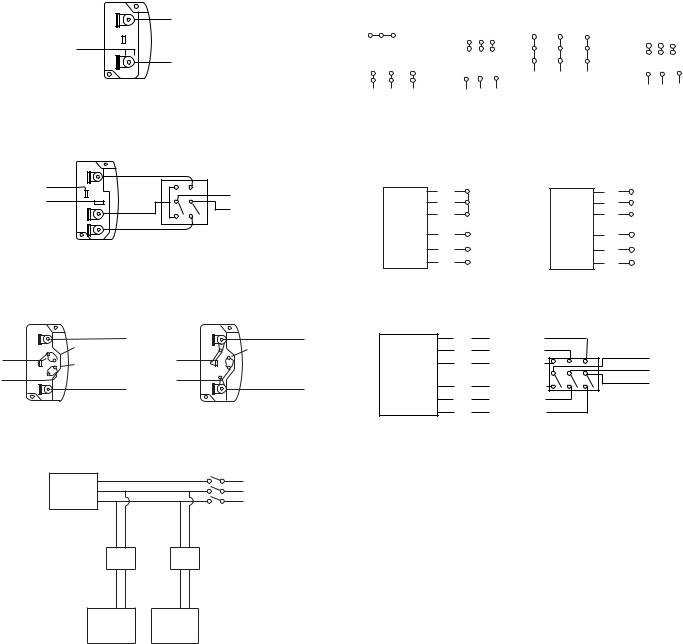
Wiring Diagrams
Single Speed, Single Phase Motor
Ground A
L1
T-1
Line
T-4
L 2
Ground B
When ground is required, attach to ground A or B with no. 6 thread forming screw. To reverse, interchange T-1 and T-4.
2 Speed, 2 Winding, Single Phase Motor
|
Ground A |
|
T-1 |
High Speed |
|
L1 |
||
T-4 |
||
|
L2 Line |
|
|
Low Speed |
Ground B
When ground required, attach to ground A or B with No. 6 thread forming screw. To reverse, interchange T-1 and T-4 leads.
Single Speed, Single Phase, Dual Voltage
Ground A |
Ground A |
Wiring Diagrams
3 Phase, 9 Lead Motor |
|
3 Phase, 9 Lead Motor |
|
|||||||||
Y-Connection |
|
|
|
Delta-Connection |
|
|
|
|||||
Low Voltage |
High Voltage |
Low Voltage |
High Voltage |
|||||||||
208/230 Volts |
460 Volts |
208/230 Volts |
460 Volts |
|||||||||
|
4 5 |
6 |
|
4 |
5 |
6 |
7 |
8 |
9 |
7 |
8 |
9 |
|
|
7 8 |
9 |
6 |
4 |
5 |
|
|
|
|||
1 |
2 |
3 |
|
1 |
2 |
3 |
4 5 |
6 |
||||
|
1 2 3 |
L1 |
|
1 |
|
2 |
3 |
|||||
7 8 9 |
|
L2 L3 |
|
|
L3 |
|||||||
|
L |
L L |
L |
L L |
|
|
L1 L2 |
|||||
|
1 |
2 |
3 |
1 |
2 |
3 |
|
|
|
|
|
|
To reverse, interchange any 2 line leads.
2 Speed, 1 Winding, 3 Phase Motor
High Speed |
|
Low Speed |
L1 |
|
1 |
|
|
1 |
|
2 |
Together |
2 |
L2 Line |
|
3 |
|
|
3 |
L3 |
Motor |
L1 |
|
Motor |
|
4 |
|
4 |
|
|
5 |
L2 |
Line |
5 |
Open |
6 |
L3 |
|
6 |
|
To reverse, interchange any 2 line leads. Motors require magnetic control.
2 Speed, 2 Winding, 3 Phase
|
Link A |
L 1 |
|
L1 |
|
|
|
Link A & B |
|
T-5 |
Link B |
Line |
T-5 |
Line |
|
|
|||
J-10 |
Low Voltage |
L 2 |
J-10 |
L2 |
|
|
|||
|
|
|
||
|
Ground B |
|
|
Ground B |
When ground required, attach to ground A or B with No. 6 thread forming screw. To reverse, interchange T-5 and J-10 leads.
Typical Damper Motor Schematic
|
T3 |
Low Speed |
|
|
|
T2 |
Low Speed |
L1 |
|
|
T1 |
Low Speed |
Line |
|
Motor |
L 2 |
|||
|
T |
High Speed |
L 3 |
|
|
11 |
High Speed |
|
|
|
T12 |
|
|
|
|
T13 |
High Speed |
|
|
To reverse: High Speed-interchange leads T11 and T12.
Low Speed-interchange leads T1 and T2. Both Speeds-interchange any 2 line leads.
Fan |
L3 |
|
L2 |
||
Motor |
||
L1 |
||
|
Transformer** |
Transformer** |
|
Damper |
Second |
|
Damper |
||
Motor* |
||
Motor |
||
|
For 3 phase, damper motor voltage should be the same between L1 and L2. For single phase application, disregard L3. *Damper motors may be available in 115, 230 and 460 volt models. The damper motor nameplate voltage should be verified prior to connection. **A transformer may be provided in some installations to correct the damper motor voltage to the specified voltage.
Wiring Installation
All wiring should be in accordance with local ordinances and the National Electrical Code, NFPA 70. Ensure the power supply (voltage, frequency, and current carrying capacity of wires) is in accordance with the motor nameplate. Refer to the Wiring Diagrams.
Lock off all power sources before unit is wired to power source.
Direct drive - Wire the electrical box on the blower housing.
Belt drive - The motor can be wired directly since the motor is external to the fan.
Leave enough slack in the wiring to allow for motor movement when adjusting belt tension. Some fractional motors have to be removed in order to make the connection with the terminal box at the end of the motor. To remove motor, remove bolts securing motor base to power assembly. Do not remove motor mounting bolts.
Follow the wiring diagram in the disconnect switch and the wiring diagram provided with the motor. Correctly label the circuit on the main power box and always identify a closed switch to promote safety (i.e., red tape over a closed switch).
2

1/4 |
inch |
|
1foot
Figure 1
Belt and Pulley Installation
If your fan is a direct drive, proceed to Blower Installation.
Belt tension is determined by the sound the belts make when the fan is first started. Belts will produce a loud squeal which dissipates after the fan is operating at full capacity. If the belt tension is too tight or too loose, lost efficiency and possible damage can occur.
Do not change the pulley pitch diameter to change tension. This will result in a different fan speed.
a.Loosen motor plate adjustment nuts on L-bolts and move motor plate in order that the belts can easily slip into the grooves on the pulleys. Never pry, roll, or force the belts over the rim of the pulley.
b.Adjust the motor plate until proper tension is reached. For proper tension, a deflection of approximately 1/4” per foot of center distance should be obtained by firmly pressing the belt. Refer to Figure1.
c.Lock the motor plate adjustment nuts in place.
d.Ensure pulleys are properly aligned. Refer to Figure 2.
Tolerance |
|
|
OFFSET |
Center Distance |
Maximum |
|
A |
Gap |
W |
|
|
|
|
||
Up thru 12” |
1/16” |
|
|
12” up through 48 |
1/8” |
|
|
Over 48” |
1/4” |
|
|
|
|
X |
CENTER |
|
|
DISTANCE |
|
|
|
|
|
|
|
Y |
(CD) |
|
|
|
|
Figure 2 |
|
Z |
B |
|
|
|
ANGULAR OFFSET/ANGULAR
GAP |
GAP |
Pulley Alignment
Pulley alignment is adjusted by loosening the motor pulley setscrew and by moving the motor pulley on the motor shaft.
Figure 2 indicates where to measure the allowable gap for the drive alignment tolerance. All contact points (indicated by WXYZ) are to have a gap less than the tolerance shown in the table. When the pulleys are not the same width, the allowable gap must be adjusted by half of the difference in width. Figure 3 illustrates using a carpenter’s
square to adjust the position of the motor pul-
ley until the belt is parallel to the longer leg of the square.
Blower Installation
The blower is shipped with the motor in the
12 o’clock position and the feet are shipped loose.
a. Upon receipt of the fan, remove the
eight (8) feet shipped with the fan and ensure the feet are the correct type. Refer to Figure 4.
b.Determine how the fan is to be mounted. Refer to
Figure 5.
c.Remove the 5/16” bolt(s) from the corner of the housing in which the foot is to be attached.
d.Place the foot over the open bolt hole(s) and bolt the
foot to the unit. Refer to Figure 4.
Foot Mounting Illustrations
Sizes 70 - 135 |
Sizes 150 - 225 |
Sizes 245 - 402 |
View of A or E Foot Assembly
Figure 4
(A) |
Not on direct drive |
Not on direct drive |
(B) |
Not on direct drive |
(C) |
|
|
Not on direct drive
Figure 5 |
(D) |
(E) |
Not on direct drive |
3
SQN Optional Side Discharge Installation
Upon receiving a SQN for a side discharge installation, please note that the rear discharge block-off panel is installed on the unit and that the correct number of side discharge duct connection collars are provided (4 steel flanges for a single side discharge and 8 for dual).
To install the side discharge duct connection collar, remove the appropriate access door. Install the side discharge duct connection collar using the bolts that were removed with the access door. Then connect the duct work.
See page 5 for examples.
|
Side Discharge |
|
Duct Connection |
Rear Discharge |
Collar |
Block-off Panel |
|
NOTE
Original Loren Cook Company labels must remain with the unit. This may require swapping access doors from one side to the other.
Final Installation Steps
a.Ensure that all accessories are installed.
b.Ensure that the blower is secured to ductwork.
c.Inspect wheel-to-inlet clearance. Ensure wheel does not rub against the inlet.
d.Test the fan to ensure the rotation of the wheel is the same as indicated by the rotation label.
e.Inspect for correct amperage with an ammeter and correct voltage with a voltmeter.
Do not allow the fan to run in the wrong direction. This will overheat the motor and cause serious damage. For 3-phase motors, if the fan is running in the wrong direction, check the control switch. It is possible to interchange two leads at this location so that the fan is operating in the correct direction.
Operation
Pre-Start Checks
a.Lock out all the primary and secondary power sources.
b.Inspect and tighten fasteners and setscrews, particularly fan mounting and bearing fasteners. Refer to
Torque chart.
c.Inspect belt tension and pulley alignment.
d.Inspect motor wiring.
e.Ensure fan and ductwork are clean and free of debris.
f.Close and secure all access doors.
g.Restore power to the fan.
Recommended Torque for Setscrews/Bolts (IN/LB.)
|
Setscrews |
|
|
|
|
|
|
|
Hold Down Bolts |
||
|
Key Hex |
Recommended |
|||
|
Torque |
|
|
||
Size |
Across |
|
|
||
|
Flats |
Min. |
Max. |
Size |
Wrench |
|
|
|
|
|
Torque |
No.10 |
3/32” |
28 |
33 |
3/8”-16 |
240 |
1/4” |
1/8” |
66 |
80 |
1/2”-13 |
600 |
|
|
|
|
|
|
5/16” |
5/32” |
126 |
156 |
5/8”-11 |
1200 |
|
|
|
|
|
|
3/8” |
3/16” |
228 |
275 |
3/4”-10 |
2100 |
7/16” |
7/32” |
29 |
348 |
7/8”-9 |
2040 |
|
|
|
|
|
|
1/2” |
1/4” |
42 |
504 |
|
|
|
|
|
|
|
|
5/8” |
5/16” |
92 |
1104 |
|
|
3/4” |
3/8” |
120 |
1440 |
|
|
Start Up
Turn the fan on. In variable speed units, set the fan to its lowest speed and inspect for the following:
•Direction of rotation.
•Excessive vibration.
•Unusual noise.
•Bearing noise.
•Improper belt alignment or tension (listen for squealing).
•Improper motor amperage or voltage.
If a problem is discovered, immediately shut the fan off. Lock out all electrical power and check for the cause of the trouble. See Troubleshooting on page 7.
Inspection
Inspection of the fan should be conducted at the first 30 minute, 8 hour and 24 hour intervals of satisfactory operation. During the inspections, stop the fan and inspect as per the chart below.
30 Minute Interval
Inspect bolts, setscrews, and motor mounting bolts. Adjust and tighten as necessary.
8 Hour Interval
Inspect belt alignment and tension. Adjust and tighten as necessary.
24 Hour Interval
Inspect belt tension. Adjust and tighten as necessary.
Maintenance
Establish a schedule for inspecting all parts of the fan. The frequency of inspection depends on the operating conditions and location of the fan.
Inspect fans exhausting corrosive or contaminated air within the first month of operation. Fans exhausting contaminated air (airborne abrasives) should be inspected every three months.
Yearly inspections are recommended for fans exhausting non-contaminated air.
It is recommended the following inspections be conducted twice per year.
•Inspect bolts and setscrews for tightness. Tighten as necessary. Refer to Torque chart.
•Inspect belt wear and alignment. Replace worn belts with new belts and adjust alignment as needed. Refer to Belt and Pulley Installation.
•Bearings should be inspected as recommended in the
Conditions Chart.
4
Loading...