


 Loading...
Propeller Wall
Propeller Wall Fans
INSTALLATION, OPERATION, AND MAINTENANCE MANUAL
This publication contains the installation, operation and maintenance procedures for standard units of the
Propeller Wall and X.StreamPropeller Wall Fans.
•APD |
•APB |
•AWBS/AWBE |
•EPB |
•EPD |
•EWB |
•EWD |
•EWBSM |
•SWD |
•SPB |
•SPD |
•SWDS |
•XLWHS/XMWHS |
•XLWH/XMWH |
|
•XLPH/XMPH |
•XLPHS/XMPHS |
|
•XLW/XMW |
•XLWS/XMWS |
|
•XLP/XMP |
•XLPS/XMPS |
|
Carefully read this publication prior to any installation or maintenance procedure.
Loren Cook catalog, Propeller Wall and X.Stream, provides additional information describing the equipment, fan performance, available accessories and specification data.
For additional safety information, refer to AMCA publication 410-96, Safety Practices for Users and Installers of Industrial and Commercial Fans.
All of the publications listed above can be obtained from Loren Cook Company by phoning 417.869.6474, extension 166; by FAX at 417.832.9431; or by e-mail at info@lorencook.com.
For information and instructions on special equipment, contact Loren Cook Company at 417.869.6474.
Receiving and Inspection
Carefully inspect the fan and accessories for any damage and shortage immediately upon receipt of the fan.
•Turn the propeller by hand to ensure it turns freely and does not bind.
•Record on the Delivery Receipt any visible sign of damage.
Handling
Lift propeller wall fans by attachment to the power assembly or by the shipping carton. Never lift by the shaft, motor or housing.
Storage
If the fan is stored for any length of time prior to installation, coat the shaft with grease or a rust preventative compound. Store it in its original shipping crate and protect it from dust, debris and the weather.
Rotate the wheel several revolutions every three to five days to keep a coating of grease on all internal bearing parts.
WARNING
This unit has rotating parts. Safety precautions should be exercised at all times during installation, operation, and maintenance.
ALWAYS disconnect power prior to working on fan.
Installation
Fans mounted to a wall require a different wall opening size than fans mounted in wall collars or wall housings. For specific dimensions, refer to the submittal drawing for the specific fan type.
Motor Installation
To prevent damage to the fan during shipping, motors 5 HP and larger, and extremely heavy motors (cast iron or severe duty) are shipped loose and must be field mounted by bolting the motor on the motor mounting plate in the existing slots.
The motor should be mounted in order that the motor plate is between the fan shaft and the motor shaft.
a.Remove the motor plate mounting bolts and motor plate.
b.Remove the motor mounting bolts from the motor plate.
c.Mount the motor to the motor plate aligning the appropriate holes.
d.Place the motor plate on the power assembly and reinstall the mounting bolts.
Personal Safety
Disconnect switches are recommended. Place the disconnect switch near the fan in order that the power can be swiftly cut off in case of an emergency, and in order that maintenance personnel are provided complete control of the power source.
AWB
1/4 |
inch |
|
1 |
foot |
|
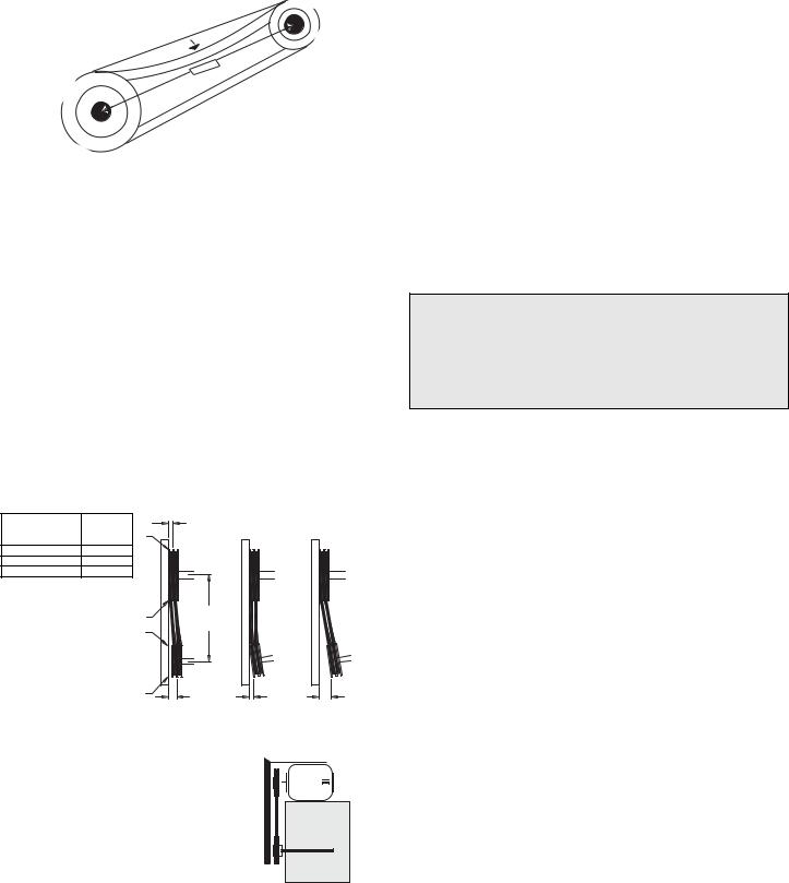
Figure 1
Belt and Pulley Installation
Belt tension is determined by the sound of the belts when the fan is first started. The belts will produce a loud squeal, which dissipates after the fan is operating at full capacity. If belt tension is too tight or too loose, lost efficiency and damage can occur.
Do not change the pulley pitch diameter to change tension. The change will result in a different fan speed.
a.Loosen the motor plate adjustment nuts on motor base and move motor plate in order that the belts can easily slip into the grooves on the pulleys. Never pry, roll, or force the belts over the rim of the pulley.
b.Adjust the motor plate until proper tension is reached. For proper tension, a deflection of approximately 1/4” per foot of center distance should be obtained by firmly pressing the belt. Refer to Figure 1.
c.Lock the motor plate adjustment nuts in place.
d.Ensure pulleys are properly aligned. Refer to Figure 2.
Tolerance |
|
|
OFFSET |
Center Distance |
Maximum |
|
A |
Gap |
W |
|
|
|
|
||
Up thru 12” |
1/16” |
|
|
12” up through 48 |
1/8” |
|
|
Over 48” |
1/4” |
|
|
|
|
X |
CENTER |
|
|
DISTANCE |
|
|
|
|
|
|
|
Y |
(CD) |
|
|
|
|
Figure 2 |
|
Z |
B |
|
|
ANGULAR OFFSET/ANGULAR
GAP |
GAP |
Pulley Alignment
Pulley alignment is adjusted by loosen-  ing the motor pulley setscrew and by


 moving the motor pulley on the motor


 shaft.
Figure 2 indicates where to measure
the allowable gap for the drive alignment tolerance. All contact points (indicated by WXYZ) are to have a gap less than the tolerance shown in the table. When the
pulleys are not the same width, the allowable gap must be adjusted by half of the difference in width. Figure 3 illustrates using a carpenter’s square to adjust the position of the motor pulley until the belt is parallel to the longer leg of the square.
Fan Installation
Insert the fan into the wall opening and secure with lag screws, anchor bolts, or other suitable fasteners.
Always mount belt drive wall fans in order that the motor base is below the fan shaft.
Wiring Installation
All wiring should be in accordance with local ordinances and the National Electrical Code, NFPA 70. Ensure the power supply (voltage, frequency, and current carrying capacity of wires) is in accordance with the motor nameplate. Refer to the Wiring Diagrams, next page.
Lock off all power sources before unit is wired to power source.
Leave enough slack in the wiring to allow for motor movement when adjusting belt tension. Some fractional motors have to be removed in order to make the connection with the terminal box at the end of the motor.
Personal Safety
Disconnect switches are recommended. Place the disconnect switch near the fan in order that the power can be swiftly cut off in case of an emergency, and in order that maintenance personnel are provided complete control of the power source.
Follow the wiring diagram in the disconnect switch and the wiring diagram provided with the motor. Correctly label the circuit on the main power box and always identify a closed switch to promote safety (i.e., red tape over a closed switch).
Wall Fans
a.Extend wires to the fan.
b.Prevent excess wire from entering the shaft and propeller area by restraining the excess wire to a point outside
the base.
Wall Fans with Wire Guard
a.Remove end panel from the wire guard to gain access to the motor.
b.Extend wires through a side panel of the wire guard to gain access to the motor.
c.Prevent excess wire from entering the shaft and propel-
ler area by restraining the excess wire to a point outside the base.
Wall Fans with Wall Housing
a.Remove end guard from the wall housing.
b.Drill a hole through either side panel at a convenient location and pull the wires through. Do not pull wires through wire guard at the back panel.
c.Restrain the incoming wire at the side panel to prevent excess wire from entering the shaft and propeller area.
Shutter Installation
If your fan is supplied with a shutter, follow the direction below. If your fan is not supplied with a shutter, proceed to
Final Installation Steps.
To ensure long-life, make a weather-proof seal by using a good quality silicon caulking under the shutter flange.
a. Place the shutter into the wall opening.
2
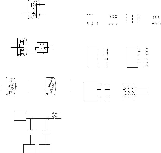
Wiring Diagrams
Single Speed, Single Phase Motor
Ground A
L1
T-1
Line
T-4
L 2
Ground B
When ground is required, attach to ground A or B with no. 6 thread forming screw. To reverse, interchange T-1 and T-4.
2 Speed, 2 Winding, Single Phase Motor
|
Ground A |
|
T-1 |
High Speed |
|
L1 |
||
T-4 |
||
|
L2 Line |
|
Ground B |
Low Speed |
|
|
When ground required, attach to ground A or B with No. 6 thread forming screw. To reverse, interchange T-1 and T-4 leads.
Wiring Diagrams
3 Phase, 9 Lead Motor
3 Phase, 9 Lead Motor |
|
3 Phase, 9 Lead Motor |
|
||||||||||
Y-Connection |
|
|
|
|
Delta-Connection |
|
|
|
|||||
Low Voltage |
High Voltage |
Low Voltage |
High Voltage |
||||||||||
208/230 Volts |
|
460 Volts |
|||||||||||
|
208/230 Volts |
460 Volts |
|||||||||||
|
4 5 |
6 |
|
|
4 |
5 |
6 |
7 |
8 |
9 |
7 |
8 |
9 |
|
|
|
7 8 |
9 |
6 |
4 |
5 |
|
|
|
|||
1 |
2 |
|
3 |
|
1 |
2 |
3 |
4 5 |
6 |
||||
|
1 |
2 |
3 |
L1 |
|
1 |
|
2 |
3 |
||||
7 |
8 |
|
9 |
|
|
|
|
L2 L3 |
|
|
L3 |
||
|
L |
L L |
L |
L L |
|
|
L1 L2 |
||||||
|
1 |
2 |
3 |
|
1 |
2 |
3 |
|
|
|
|
|
|
To reverse, interchange any 2 line leads.
2 Speed, 1 Winding, 3 Phase Motor
High Speed |
|
Low Speed |
L1 |
|
1 |
|
|
1 |
|
2 |
Together |
2 |
L2 Line |
|
3 |
|
|
3 |
L3 |
Motor |
L1 |
|
Motor |
|
4 |
|
4 |
|
|
5 |
L2 |
Line |
5 |
Open |
6 |
L3 |
|
6 |
|
Single Speed, Single Phase, Dual Voltage
|
Ground A |
|
|
Ground A |
|
Link A |
L 1 |
|
L1 |
|
|
|
Link A & B |
|
T-5 |
Link B |
Line |
T-5 |
Line |
|
|
|||
J-10 |
Low Voltage |
L 2 |
J-10 |
L2 |
|
|
|||
|
|
|
||
|
Ground B |
|
|
Ground B |
When ground required, attach to ground A or B with No. 6 thread forming screw. To reverse, interchange T-5 and J-10 leads.
To reverse, interchange any 2 line leads. Motors require magnetic control.
2 Speed, 2 Winding, 3 Phase
|
T3 |
Low Speed |
|
|
|
T2 |
Low Speed |
L1 |
|
|
T1 |
Low Speed |
Line |
|
Motor |
L 2 |
|||
|
T |
High Speed |
L 3 |
|
|
11 |
High Speed |
|
|
|
T12 |
|
|
|
|
T13 |
High Speed |
|
|
Typical Damper Motor Schematic
Fan |
L3 |
|
L2 |
||
Motor |
||
L1 |
||
|
Transformer**

 Transformer**
To reverse: High Speed-interchange leads T11 and T12.
Low Speed-interchange leads T1 and T2. Both Speeds-interchange any 2 line leads.
For 3 phase, damper motor voltage should be the same between L1 and L2. For single phase application, disregard L3. *Damper motors may be available in 115, 230 and 460 volt models. The damper motor nameplate voltage should be verified prior to connection. **A transformer may be provided in some installations to correct the damper motor voltage to the specified voltage.
Damper Second
Motor* Damper
Motor
b.Mount the shutter to the supporting surface using Number 12 sheet metal screws on six inch centers around the perimeter.
c.Manually operate the shutter to ensure the blades move freely.
Typical Installation
Refer to page 5.
Final Installation Steps
a.Inspect fasteners and setscrews, particularly fan mounting and bearing fasteners, and tighten according to the recommended torque shown in the table on page 4, Recommended Torque for Setscrews/Bolts.
b.Inspect for correct voltage with voltmeter.
c.Ensure all accessories are installed.
d.Test the fan to be sure the rotation is the same as indicated by the arrow marked Rotation.
Do not allow the fan to run in the wrong direction. This will overheat the motor and cause serious damage. For 3-phase motors, if the fan is running in the wrong direction, check the control switch. It is possible to interchange two leads at this location so that the fan is operating in the correct direction.
Operation
Pre-Start Checks
a.Lock out all the primary and secondary power sources.
b.Inspect fasteners and setscrews, particularly those used for mounting the unit, and tighten if necessary.
c.Inspect belt tension and pulley alignment. (Remember, if belt tension is correct, a loud squeal occurs as the fan increases to full power.)
d.Inspect motor wiring.
e.Ensure the belt touches only the pulleys.
f.Rotate the prop to ensure it does not rub against the venturi.
3

g.Ensure fan and ductwork are clean and free of debris.
h.Test the fan to ensure the rotation of the propeller is the same as indicated by the rotation label.
i.Close and secure all access doors.
j.Restore power to unit.
Start Up
Turn the fan on. In variable speed units, set the fan to its lowest speed. Inspect for the following:
•Direction of rotation.
•Excessive vibration.
•Unusual noise.
•Bearing noise.
•Improper belt alignment or tension (listen for a continuous squealing noise).
•Improper motor amperage or voltage.
If a problem is discovered, immediately shut off the fan. Lock out all electrical power and check for the cause of the trouble. Refer to Troubleshooting, page 7.
Recommended Torque for Setscrews/Bolts (IN/LB.)
|
Setscrews |
|
|
|
|
|
Key Hex |
Recommended Torque |
Hold Down Bolts |
||
Size |
Across |
Inch-lbs. |
|
|
|
|
Flats |
Min. |
Max. |
Size |
Wrench Torque |
|
(inch-lbs) |
||||
|
|
|
|
|
|
No.10 |
3/32” |
28 |
33 |
3/8”-16 |
240 |
1/4” |
1/8” |
66 |
80 |
1/2”-13 |
600 |
5/16” |
5/32” |
126 |
156 |
5/8”-11 |
1200 |
3/8” |
3/16” |
228 |
275 |
3/4”-10 |
2100 |
7/16” |
7/32” |
348 |
384 |
7/8”-9 |
2040 |
1/2” |
1/4” |
504 |
600 |
1”-8 |
3000 |
5/8” |
5/16” |
1104 |
1200 |
1-1/8”-7 |
4200 |
3/4” |
3/8” |
1440 |
1800 |
1-1/4”-7 |
6000 |
Inspection
Inspection of the fan should be conducted at the first 30 minute, 8 hour and 24 hour intervals of satisfactory operation. During the inspections, stop the fan and inspect as per directions below.
30 Minute Interval
Inspect bolts, setscrews, and motor mounting bolts. Adjust and tighten as necessary.
8 Hour Interval
Inspect belt alignment and tension. Adjust and tighten as necessary.
24 Hour Interval
Inspect belt tension. Adjust and tighten as necessary.
Maintenance
Establish a schedule for inspecting all parts of the fan.The frequency of inspection depends on the operating conditions and location of the fan.
Inspect fans exhausting corrosive or contaminated air within the first month of operation. Fans exhausting contaminated air (airborne abrasives) should be inspected every three months. Clean the propeller and air inlets if material build-up is excessive. Excessive build-up can cause imbalance and failure of the propeller.
Regular inspections are recommended for fans exhausting non-contaminated air.
It is recommended the following inspections be conducted twice per year.
•Inspect bolts and setscrews for tightness. Tighten as necessary.
•Inspect belt wear and alignment. Replace worn belts with new belts and adjust alignment as needed. See Belt and Pulley Installation, on page 2.
•Bearings should be inspected as recommended in the
Conditions Chart, below.
•Inspect for cleanliness. Clean exterior surfaces only. Removing dust and grease on motor housing assures proper motor cooling.
Lubricants
Loren Cook Company uses petroleum lubricant in a lithium base conforming to NLGI grade 2 consistency. Other grades of grease should not be used unless the bearings and lines have been flushed clean. If another grade of grease is used, it should be lithium-based.
A NLGI grade 2 grease is a light viscosity, low-torque, rustinhibiting lubricant that is water resistant. Its temperature range is from -30°F to +200°F and capable of intermittent highs of +250°F.
Motor Bearings
Motors are provided with prelubricated bearings. Any lubrication instructions shown on the motor nameplate supersede instructions below.
Direct Drive 1050/1075,1200,1300 &1500 rpm units use a prelubricated sleeve bearing that has a oil saturated wicking material surrounding it. The initial factory lubrication is adequate for up to 10 years of operation under normal conditions. However, it is advisable to add lubricant after 3 years. Use only LIGHT grade mineral oil or SAE 10W oil up to 30 drops. If the unit has been stored for a year or more it is advisable to lubricate as directed above. For units in severe conditions, lubrication intervals should be reduced to half.
Motors without sleeve bearings (as described above) will have grease lubricated ball or roller bearings. Motor bearings without provisions for relubrication will operate up to 10 years under normal conditions with no maintenance. In severe applications, high temperatures or excessive contaminates, it is advisable to have the maintenance department disassemble and lubricate the bearings after 3 years of operation to prevent interruption of service.
For motors with provisions for relubrication, follow intervals of the table below.
Relubrication Intervals
|
|
|
NEMA Frame Size |
|
|
||
|
|
|
|
|
|
||
|
Up to and |
213T-365T |
404T and larger |
||||
Service |
including 184T |
||||||
|
|
|
|
||||
Conditions |
|
|
|
|
|
|
|
1800 RPM |
Over 1800 |
1800 RPM |
Over 1800 |
1800 RPM |
Over 1800 |
||
|
|||||||
|
and less |
RPM |
and less |
RPM |
and less |
RPM |
|
|
|
|
|
|
|
|
|
Standard |
3 yrs. |
6 months |
2 yrs. |
6 months |
1 yr. |
3 months |
|
|
|
|
|
|
|
|
|
Severe |
1 yr. |
3 months |
1 yr. |
3 months |
6 months |
1 months |
|
|
|
|
|
|
|
|
|
Motors are provided with a polyurea mineral oil NGLI #2 grease. All additions to the motor bearings are to be with a compatable grease such as Exxon Mobil Polyrex EM and Chevron SRI.
The above intervals should be reduced to half for vertical shaft installations.
4

Fan Bearings
The fan bearings are provided prelubricated. Any specialized lubrication instructions on fan labels supersedes information provided herein. Bearing grease is a petroleum lubricant in a lithium base conforming to a NLGI #2 consistency. If user desires to utilize another type of lubricant, they take responsibility for flushing bearings and lines, and maintaining a lubricant that is compatible with the installation.
A NLGI #2 grease is a light viscosity, low-torque, rustinhibiting lubricant that is water resistant. Its temperature range is from -30°F to 200°F and capable of intermittent highs of 250°F.
Bearings should be relubricated in accordance with the condition chart below.
For best results, lubricate the bearing while the fan is in operation. Pump grease in slowly until a slight bead forms around the bearing seals. Excessive grease can damage seal and reduce life through excess contamination and/or loss of lubricant.
In the event that the bearing cannot be seen, use no more than three injections with a hand operated grease gun.
Speed Increase
Close the pulley in order that the belt rides higher in the groove (larger pitch diameter). Ensure that the RPM limits of the fan and the horsepower limits of the motor are maintained.
Pulley and Belt Replacement
a.Clean the motor and fan shafts.
b.Loosen the motor plate mounting bolts to relieve the belt tension. Remove the belt.
c.Loosen the pulley setscrews and remove the pulleys from the shaft.
If excessive force is required to remove the pulleys, a three-jaw puller can be used. This tool, however, can easily warp a pulley. If the puller is used, inspect the trueness of the pulley after it is removed from the shaft. The pulley will need replacement if it is more than 0.020 inch out of true.
d.Clean the bores of the pulleys and place a light coat of oil on the bores.
e.Remove grease, rust and burrs from the shaft.
f.Place fan pulley on the fan shaft and the motor pulley on the motor shaft. Damage to the pulleys can occur when excessive force is used in placing the pulleys on their respective shafts.
Conditions Chart
RPM |
Temp °F |
Greasing Interval |
|
|
|
|
|
Up to 1000 |
-30 to 120 |
6 months |
|
|
|
||
120 to 200 |
2 months |
||
|
|||
|
|
|
|
1000 to 3000 |
-30 to 120 |
3 months |
|
|
|
||
120 to 200 |
1 month |
||
|
|||
|
|
|
|
Over 3000 |
-30 to 120 |
1 month |
|
|
|
||
120 to 200 |
2 weeks |
||
|
|||
|
|
|
|
Any Speed |
< -30 |
Consult Factory |
|
|
|
|
|
Any Speed |
> 200 |
1 week |
|
|
|
|
For moist or otherwise contaminated installations; divide the interval by a factor of 3. For vertical shaft installations divide the interval by a factor of 2.
Motor Services
Should the motor prove defective within a one-year period, contact your local Loren Cook representative or your nearest authorized electric motor service representative.
Changing Shaft Speed
All belt driven Propeller Wall fans with motors up to and including 5HP are equipped with variable pitch pulleys. To change the fan speed, perform the following:
a.Loosen setscrew on driver (motor) pulley and remove key, if equipped.
b.Turn the pulley rim to open or close the groove facing. If the pulley has multiple grooves, all must be adjusted to the same width.
c.After adjustment, inspect for proper belt tension.
Speed Reduction
Open the pulley in order that the belt rides deeper in the groove (smaller pitch diameter).
Maximum RPM
SWD |
Maximum |
EWB |
Maximum |
AWB |
Maximum |
Size |
RPM |
Size |
RPM |
Size |
RPM |
8 |
1690 |
24 |
1675 |
24 |
1510 |
10 |
1550 |
30 |
1370 |
30 |
1145 |
12 |
1615 |
36 |
1310 |
36 |
990 |
14 |
1130 |
42 |
1175 |
42 |
905 |
16 |
1115 |
48 |
1215 |
48 |
900 |
18 |
1095 |
54 |
960 |
- |
- |
20 |
1075 |
60 |
890 |
- |
- |
24 |
1050 |
72 |
700 |
- |
- |
Maximum RPM
APB |
Maximum |
XLP/XLPS |
Maximum |
XLPH/XLPHS |
Maximum |
Size |
RPM |
Size |
RPM |
Size |
RPM |
24 |
1005 |
20 |
1280 |
- |
- |
30 |
800 |
24 |
1012 |
24 |
1110 |
36 |
645 |
30 |
666 |
30 |
930 |
42 |
660 |
36 |
566 |
36 |
714 |
48 |
605 |
42 |
424 |
42 |
610 |
- |
- |
48 |
356 |
48 |
512 |
- |
- |
54 |
316 |
54 |
472 |
- |
- |
60 |
260 |
60 |
446 |
Maximum RPM
|
XMP/XMPS |
Maximum |
XMPH/ |
Maximum |
XLW/ |
Maximum |
|
XMPHS |
XLWS |
||||
|
Size |
RPM |
Size |
RPM |
Size |
RPM |
|
|
|
|
|
||
|
20 |
1280 |
- |
- |
20 |
1276 |
|
24 |
1276 |
24 |
1410 |
24 |
1018 |
|
30 |
830 |
30 |
1172 |
30 |
674 |
|
36 |
680 |
36 |
838 |
36 |
570 |
|
42 |
498 |
42 |
716 |
42 |
422 |
|
48 |
414 |
48 |
596 |
48 |
356 |
|
54 |
346 |
54 |
516 |
54 |
320 |
|
60 |
318 |
60 |
474 |
60 |
256 |
|
Maximum |
RPM |
|
|
|
|
|
XLWH/ |
Maximum |
XMW/ |
Maximum |
XMWH/ |
Maximum |
|
XLWHS |
RPM |
XMWHS |
RPM |
XMWHS |
RPM |
|
Size |
Size |
Size |
|||
|
|
|
|
|||
|
- |
- |
20 |
1462 |
- |
- |
|
24 |
1126 |
24 |
1272 |
24 |
1400 |
|
30 |
932 |
30 |
860 |
30 |
1184 |
|
36 |
720 |
36 |
672 |
36 |
864 |
|
42 |
610 |
42 |
498 |
42 |
718 |
|
48 |
516 |
48 |
416 |
48 |
600 |
|
54 |
478 |
54 |
350 |
54 |
522 |
|
60 |
438 |
60 |
320 |
60 |
476 |
5
Loading...