


 Loading...
CIC/UCIC
Tubular Centrifugal Blowers
INSTALLATION, OPERATION, AND MAINTENANCE MANUAL
This publication contains the installation, operation and maintenance instructions for standard units of the
CIC/UCIC-Tubular Centrifugal Blowers. Carefully read this publication prior to any installation or maintenance procedure.
Loren Cook catalog, CIC, provides additional information describing the equipment, fan performance, available accessories, and specification data.
For additional safety information, refer to AMCA publication 410-96, Safety Practices for Users and Installers of Industrial and Commercial Fans.
All of the publications listed above can be obtained from Loren Cook Company by phoning 417/869-6474, extension 166; by FAX at 417/832-9431; or by e-mail at info@lorencook.com.
For information on special equipment, contact Loren Cook Company Customer Service Department at 417/8696474.
Receiving and Inspection
Carefully inspect the fan and accessories for any damage and shortage immediately upon receipt of the fan.
•Turn the wheel by hand to ensure it turns freely and does not bind.
•Inspect dampers for free operation of all moving parts.
•Record on the Delivery Receipt any visible sign of damage.
WARNING
This unit has rotating parts. Safety precautions should be exercised at all times during installation, operation, and maintenance.
ALWAYS disconnect power prior to working on fan.
•Periodically inspect the unit to prevent damaging conditions.
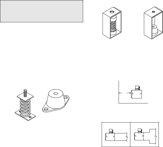
UCIC Storage
To maintain good working condition of a UCIC fan when it is stored outdoors or on a construction site, always store in upright position. Also, if the dampers are not mounted, cover discharge.
Personal Safety
Disconnect switches are recommended. Place the disconnect switch near the fan in order that the power can be swiftly cut off in case of an emergency, and in order that maintenance personnel are provided complete control of the power source.
Installation
Most motors are shipped mounted on the fans with belts and drives installed. However, extremely heavy motors and drives are shipped separately, and some motors are shipped separately due to height limitations. These motors and drives will require field installation. Please refer to page 3.
CIC Installation
Arrangements 1 and 9 (FM) are floor-mounted fans. They require a strong, level foundation of reinforced poured concrete.
The foundation’s size is determined by fan size, motor size and position, and the specific location of the installation.
Use the following guidelines to calculate foundation size:
•The overall dimensions of the foundation should extend at least 6 inches beyond the outline of the fan and its motor.
Handling
Lift the fan by the base or lifting eyes. Never lift by the shaft, motor, windband, or housing.
Storage
If the fan is stored for any length of time prior to installation, completely fill the bearings with grease or moistureinhibiting oil. Refer to Lubricants on page 6. Also, store the fan in its original crate and protect it from dust, debris and the weather.
CIC Storage
To maintain good working condition of a CIC when it is stored outdoors, or on a construction site, follow the additional steps below.
•Cover the inlet and outlet, and belt tunnel opening to prevent the accumulation of dirt and moisture in the housing.
•Periodically rotate the wheel and operate dampers (if supplied) to keep a coating of grease on all internal
bearing parts. |
CIC |
•The weight of the foundation should be 2 to 3 times the weight of the unit and its motor.
Arrangement 9 (CM) is a ceiling-mounted fan. Suspend the fan by steel rods strong enough to support the weight the fan.
UCIC Installation
The fan support (roof curb) should provide a level surface for installation. If the roof is pitched more than 1/2:12, a sloped curb must be used to correct for the incline. If the unit is installed on a non-level surface, the damper door pivot should be positioned perpendicular to the peak of the roof.
•Drill a hole in the curb shelf for conduit needed for motor wiring.
•Install the UCIC fan over the curb with the conduit location in line with the conduit hole in the curb.
•Firmly secure the unit to the curb.
Note
Although a certain amount of vibration is inherent in operating centrifugal fans, extreme vibration is a serious problem that may cause structural and mechanical failure.
Isolation
Floor Mounted Spring Isolators
a.Mount fan and motor on isolation base (if supplied).
b.Elevate fan (or isolation base) to operating height and insert blocks to hold in position.
c.Position isolators under the fan and vertically align by inserting leveling bolt through mounting holes in the fan or the base. The isolator must be installed on a level surface.
d.Adjust the isolators by turning the leveling nut counter clockwise several turns at a time alternately on each isolator until the fan weight is transferred onto the isolators and the fan raises uniformly off the blocks. Then remove the blocks.
e.Turn lock nut onto leveling bolt and secure firmly in place against the top of the mounting flange or frame.
f.Secure isolators to mounting surface.
Rubber-In-Shear Isolator
Spring Isolator
Figure 1 -Floor Mount Isolators
Floor Mounted Rubber-In-Shear (RIS) Isolators
a.Mount fan and motor on an isolation base (if supplied).
b.Elevate fan to provide room to insert isolators between the fan and foundation and block in position.
c.Position isolators under fan and secure bolts.
d.Remove blocks and allow fan to rest on floor. Isolators
must be installed on a level surface (leveling should not be required).
e. Secure isolators to mounting surface.
Ceiling Mounted Spring and Rubber-in-Shear (RIS) Isolators
a.Elevate fan to operating height and brace.
b.Attach threaded rod to overhead support structure directly above each mounting hole. Rod should extend to within a few feet of fan.
c.Attach isolator to end of threaded rod using a nut on each side of isolator bracket.
d.Insert another section of threaded rod through the fan mounting hole and isolator.
e.Attach two nuts to threaded rod in isolator.
f.Place adjusting nut and locking nut on threaded rod near fan mounting bracket.
g.Alternately rotate adjusting nut at each mounting location until the fan weight is uniformly transferred to the isolators. Remove bracing.
Ceiling Mounted Spring Isolator |
Rubber-In-Shear Ceiling Isolators |
Figure 2 - Ceiling Mount Isolators
Duct Installation
Efficient fan performance relies on the proper installation of inlet and discharge ducts. Be sure your fan conforms to the guidelines below.
Non-Ducted Inlet Clearance
If your fan has an open inlet (no duct work), the fan must be placed 1 fan wheel diameter away from walls and bulkheads.
MIN
1 DIA
Non-ducted Inlet Clearance
Free Discharge
Avoid a free discharge into the plenum. This will result in lost efficiency because it doesn’t allow for a static regain.
Correct |
Incorrect |
Free Discharge
2

Inlet Duct Turns
For ducted inlets, allow at least 3 fan wheel diameters between duct turns or elbows and the fan inlet.
Correct |
Min |
3 Dia. |
Incorrect |
Inlet Duct Turns
Discharge Duct Turns
Where possible, allow 3 duct diameters between duct turns or elbows and the fan outlet. Refer to the drawing below.
Correct
Min
3 Dia.
Incorrect
Discharge Duct Turns
Wheel-to-Inlet Clearance
The correct wheel-to-inlet clearance is critical to proper fan performance. This clearance should be verified before initial start-up since rough handling during shipment could cause a shift in fan components. Refer to wheel/inlet drawing below for correct overlap.
Adjust the overlap by loosening the wheel hub and moving the wheel along the shaft to obtain the correct value.
A uniform radial gap (space between the edge of the cone and the edge of the inlet) is obtained by loosening the inlet cone bolts and repositioning the inlet cone.
|
|
Size |
Overlap |
|
|
100 |
|
|
|
120 |
|
|
|
135 |
5/8” |
|
|
150 |
|
|
|
165 |
|
|
|
180 |
|
|
|
195 |
|
|
|
210 |
|
|
|
225 |
3/4” |
|
|
245 |
|
|
|
|
|
|
|
270 |
|
|
|
300 |
|
|
|
330 |
1” |
|
|
365 |
|
Radial Clearance |
|
402 |
|
|
445 |
|
|
|
|
|
|
|
Overlap |
490 |
|
|
540 |
|
|
|
|
1-1/4” |
|
|
|
600 |
|
Wheel/Inlet Overlap |
|
660 |
|
|
730 |
|
1/4 |
inch |
|
1 |
foot |
|
Figure 3
Belt and Pulley Installation
Belt tension is determined by the sound the belts make when the fan is first started. Belts will produce a loud squeal which dissipates after the fan is operating at full capacity. If the belt tension is too tight or too loose, lost efficiency and possible damage can occur.
Do not change the pulley pitch diameter to change tension. This will result in a different fan speed than desired.
a.Loosen motor plate adjustment nuts and move motor plate in order that the belts can easily slip into the grooves on the pulleys. Never pry, roll, or force the belts over the rim of the pulley.
b.Adjust the motor plate until proper tension is reached. For proper tension, a deflection of approximately 1/4” per foot of center distance should be obtained by firmly pressing the belt. Refer to Figure 3.
c.Lock the motor plate adjustment nuts in place.
d.Ensure pulleys are properly aligned. Refer to Figure 4.
Correct |
Incorrect |
Incorrect |
Incorrect |
Figure 4
Pulley Alignment
Pulley alignment is adjusted by loosening the motor pulley setscrew and by moving the motor pulley on the motor shaft or by moving the entire motor along the motor mounting bracket.
Figure 4 illustrates correct and incorrect pulley alignment. A recommended method of inspecting the pulley alignment is shown in Figure 5. With the
shorter leg of a carpenter’s square or other straight edge lying along the case of the motor, adjust the position of the motor pulley (or the motor until the longer leg of the square is parallel to the belt.
3
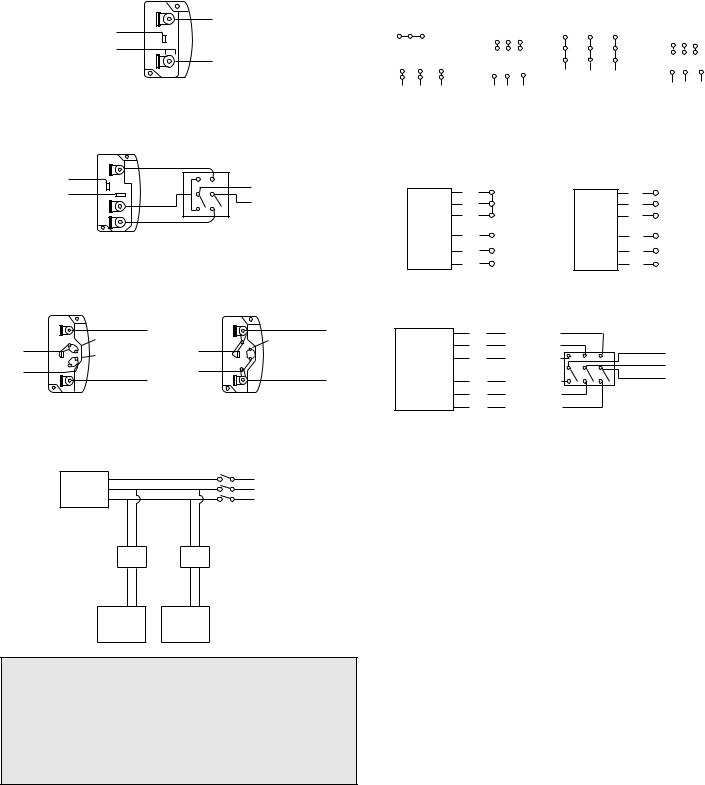
Wiring Diagrams
Single Speed, Single Phase Motor
Ground A
L1
T-1
Line
T-4
L2
Ground B
When ground is required, attach to ground A or B with no. 6 thread forming screw. To reverse, interchange T-1 and T-4.
Wiring Diagrams
3 Phase, 9 Lead Motor |
3 Phase, 9 Lead Motor |
|
|||||||||||
Y-Connection |
|
|
|
|
Delta-Connection |
|
|
|
|||||
Low Voltage |
High Voltage |
Low Voltage |
High Voltage |
||||||||||
208/230 Volts |
|
460 Volts |
208/230 Volts |
460 Volts |
|||||||||
4 |
5 6 |
|
|
4 |
5 |
6 |
7 |
8 |
9 |
7 |
8 |
9 |
|
|
|
|
|
|
6 |
4 |
5 |
|
|
|
|||
|
|
|
|
|
7 8 |
9 |
|
|
|
||||
1 |
2 |
|
3 |
|
1 |
2 |
3 |
4 5 |
6 |
||||
|
1 |
2 |
3 |
L1 |
|
1 |
|
2 |
3 |
||||
7 |
8 |
|
9 |
L2 L3 |
|
|
|
||||||
|
|
|
|
|
|
|
L3 |
||||||
L |
|
L L |
L |
L L |
|
|
L1 L2 |
||||||
1 |
2 |
3 |
|
1 |
2 |
3 |
|
|
|
|
|
|
|
2 Speed, 2 Winding, Single Phase Motor
Ground A |
2 Speed, 1 Winding, 3 Phase Motor |
|
High Speed |
T-1
T-4 L1 Line
L2
Low Speed
Ground B
When ground required, attach to ground A or B with No. 6 thread forming screw. To reverse, interchange T-1 and T-4 leads.
Single Speed, Single Phase, Dual Voltage
|
Ground A |
|
|
Ground A |
|
L1 |
|
L1 |
|
T-5 |
Link A |
|
T-5 |
Link A & B |
Link B Line |
Line |
|||
J-10 |
Low Voltage L |
2 |
J-10 |
L |
|
|
|
2 |
|
Ground B |
|
|
Ground B |
|
When ground required, attach to ground A or B with No. 6 thread forming screw. To reverse, interchange T-5 and J-10 leads.
Typical Damper Motor Schematic
High Speed |
|
Low Speed |
L1 |
|
1 |
|
|
1 |
|
2 |
Together |
2 |
L2 Line |
|
3 |
|
|
3 |
L3 |
Motor |
L1 |
|
Motor |
|
4 |
|
4 |
|
|
5 |
L2 |
Line |
5 |
Open |
6 |
L3 |
|
6 |
|
To reverse, interchange any 2 line leads. Motors require magnetic control.
2 Speed, 2 Winding, 3 Phase
|
T3 |
Low Speed |
|
|
|
T2 |
Low Speed |
L1 |
|
|
T1 |
Low Speed |
Line |
|
Motor |
L2 |
|||
|
T |
High Speed |
L3 |
|
|
11 |
High Speed |
|
|
|
T |
|
|
|
|
12 |
High Speed |
|
|
|
T |
|
|
|
|
13 |
|
|
|
To reverse: High Speed-interchange leads T11 and T12.
Low Speed-interchange leads T1 and T2. Both Speeds-interchange any 2 line leads.
Fan |
L3 |
|
L2 |
||
Motor |
||
L1 |
||
|
Transformer** |
Transformer** |
|
Damper |
Second |
|
Damper |
||
Motor* |
||
Motor |
||
|
For 3 phase, damper motor voltage should be the same between L1 and L2. For single phase application, disregard L3. Damper motors may be available in 115, 230 and 460 volt models. The damper motor nameplate voltage should be verified prior to connection. ** A transformer may be provided in some installations to correct the damper motor voltage to the specified voltage.
Personal Safety
Disconnect switches are recommended. Place the disconnect switch near the fan in order that the power can be swiftly cut off in case of an emergency, and in order that maintenance personnel are provided complete control of the power source.
Wiring Installation
All wiring should be in accordance with local ordinances and the National Electrical Code, NFPA 70. Ensure the power supply (voltage, frequency, and current carrying capacity of wires) is in accordance with the motor nameplate.
Lock off all power sources before unit is wired to power source.
Leave enough slack in the wiring to allow for motor movement when adjusting belt tension. Some fractional motors have to be removed in order to make the connection with the terminal box at the end of the motor. To remove motor, remove bolts securing motor base to power assembly. Do not remove motor mounting bolts.
Follow the wiring diagram in the disconnect switch and the wiring diagram provided with the motor. Correctly label the circuit on the main power box and always identify a closed switch to promote safety (i.e., red tape over a closed switch).
Wheel Rotation
Test the fan to ensure the rotation of the wheel is counter-clockwise as viewed from the drive side of the wheel.
4
Loading...