

Loren Cook QMXD-HP, QMXS, QMX, QMXS-HP, QMXE-HP Installation, Operation And Maintenance Manual
...Page 1
OPERATION & MAINTENACE
MANUAL
FANS
Job Name: MICKEY LELAND CPAYM
Location: HOUSTON, TEXAS
Architect: HARRISON KORNBERG
Engineer: SHAH SMITH & ASSOCIATES
Contractor: ENVIROTECH MECHANICAL
Date: APRIL 20, 2016
Submitted By: RUSTY REED
A Certified Minority Owned Small Business Enterprise
P. O. Box 630409, Houston, TX 77263-0409
Phone: (713) 266-1761 Fax: (713) 781-6532
www.distribaire.com
Page 2
QMX
®
INSTALLATION, OPERATION, AND MAINTENANCE MANUAL
This publication contains the installation, operation
and maintenance instructions for standard units of the
QMX-Mixed Flow Inline.
• QMX • QMXD-HP • QMX-HP • QMXE
• QMXS • QMXE-HP • QMXS-HP • QMXU
• QMXU-HP • QMXLE • QMXLE-HP
Carefully read this publication prior to any installation or maintenance procedure.
Loren Cook catalog, QMX, provides additional information describing the equipment, fan performance, available
accessories, and specification data.
For additional safety information, refer to AMCA publication 410-96, Safety Practices for Users and Installers of
Industrial and Commercial Fans.
All of the publications listed above can be obtained from
Loren Cook Company by phoning (417) 869-6474, extension 166; by FAX at (417) 832-9431; or by e-mail at
info@lorencook.com.
For information on special equipment, contact Loren
Cook Company Customer Service Department at (417)
869-6474.
Receiving and Inspection
Carefully inspect the fan and accessories for any damage and shortage immediately upon receipt of the fan.
• Turn the wheel by hand to ensure it turns freely and
does not bind.
• Inspect inlet vane dampers (if supplied) for free operation of all moving parts.
• Record on the Delivery Receipt any visible sign of
damage.
WARNING
This unit has rotating parts. Safety precautions
should be exercised at all times during installation,
operation, and maintenance.
ALWAYS disconnect power prior to working on fan.
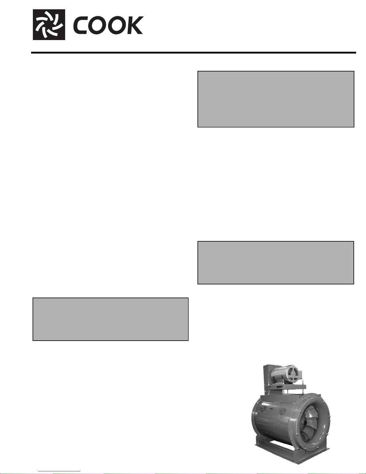
Handling
Lift the fan by lifting lugs. Never lift by the shaft, motor, or
housing.
Mixed Flow Inline
• Periodically inspect the unit to prevent damaging conditions.
Personal Safety
Disconnect switches are recommended. Place the
disconnect switch near the fan in order that the
power can be swiftly cut off in case of an
emergency, and in order that maintenance
personnel are provided complete control of the
power source.
Installation
QMX and QMX-HP can be mounted horizontally or vertically to a floor or a ceiling in various motor positions and
discharges. QMXU, QMXU-HP, QMXE, QMXE-HP, QMXS
and QMXS-HP are all designed to be roof mounted on typical roof curbs. The QMXLE or QMXLE-HP units, however,
should not be mounted on sheet metal roof curbs, but supported by integral members of the roof structure, designed
and constructed by others per local requirements and environments.
Most motors are shipped mounted on the fans with belts
and drives installed. However, extremely heavy motors are
shipped separately, and some motors are shipped separately due to height limitations. These motors and drives
will require field installation.
NOTE
Although a certain amount of vibration is inherent
in operating fans, extreme vibration is a serious
problem that may cause structural and mechanical
failure.
Isolation Installation
To help prevent vibration and noise from being transferred
to the building, isolators are recommended.
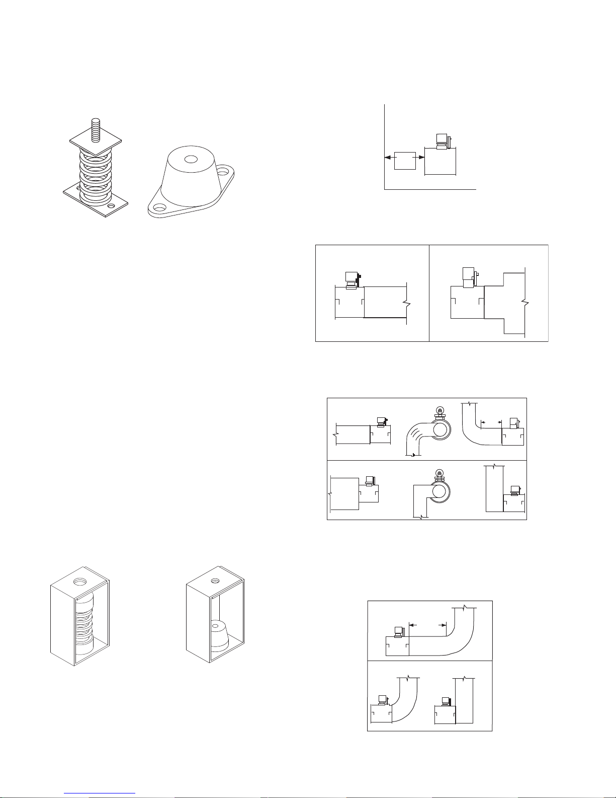
Floor Mounted Spring Isolators
a. Mount fan on isolation base or rails (if supplied).
b. Elevate fan (or isolation base) to operating height and
insert blocks to hold in position.
c. Position isolators under the fan and vertically align by
inserting leveling bolt through mounting holes in the
fan or the base. The isolator must be installed on a
level surface.
Storage
If the fan is stored for any length of time prior to installation, completely fill the bearings with grease or moistureinhibiting oil. Refer to Lubricants on page 6. Also, store the
fan in its original crate and protect it from dust, debris and
the weather.
• Cover the inlet and outlet, and belt tunnel opening to
prevent the accumulation of dirt and moisture in the
housing.
• Periodically rotate the wheel and operate inlet vane
dampers (if supplied) to keep a coating of grease on all
internal bearing parts.
QMX
Page 3
d. Adjust the isolators by turning the leveling nut counter
clockwise several turns at a time alternately on each
isolator until the fan weight is transferred onto the isolators and the fan raises uniformly off the blocks. Then
remove the blocks.
e. Turn lock nut onto leveling bolt and secure firmly in
place against the top of the mounting flange or frame.
f. Secure isolators to mounting surface.
Spring Isolator
Figure 1 -Floor Mount Isolators
Rubber-In-Shear Isolator
Floor Mounted Rubber-In-Shear (RIS) Isolators
a. Mount fan on isolation base or rails (if supplied).
b. Elevate fan to provide room to insert isolators
between the fan and foundation and block in position.
c. Position isolators under fan and secure bolts.
d. Remove blocks and allow fan to rest on floor. Isolators
must be installed on a level surface (leveling should
not be required).
e. Secure isolators to mounting surface.
Ceiling Mounted Spring and Rubber-in-Shear (RIS) Isolators
a. Elevate fan to operating height and brace.
b. Attach threaded rod to overhead support structure
directly above each mounting hole. Rod should extend
to within a few feet of fan.
c. Attach isolator to end of threaded rod using a nut on
each side of isolator bracket.
d. Insert another section of threaded rod through the fan
mounting hole and isolator.
e. Attach two nuts to threaded rod in isolator.
f. Place adjusting nut and locking nut on threaded rod
near fan mounting bracket.
g. Alternately rotate adjusting nut at each mounting loca-
tion until the fan weight is uniformly transferred to the
isolators. Remove bracing.
duct diameter of straight duct before placing an elbow or
damper. Clearance is also required on the inlet and outlet
for maintenance such as pulley or bearing replacement.
Non-Ducted Inlet Clearance
If your fan has an open inlet (no duct work), the fan must
be placed 1 effective wheel diameter away from walls and
bulkheads.
MIN
1 DIA
Non-ducted Inlet Clearance
Free Discharge
Avoid a free discharge into the plenum. This will result in
lost efficiency because it doesn’t allow for a static regain.
Correct
Free Discharge
Incorrect
Inlet Duct Turns
For ducted inlets, allow at least 3 effective wheel diameters between duct turns or elbows and the fan inlet.
MIN
Correct
Incorrect
Inlet Duct Turns
3 DIA
Discharge Duct Turns
Where possible, allow 3 duct diameters between duct
turns or elbows and the fan outlet. Refer to the drawing
below.
Ceiling Mounted Spring Isolator
Figure 2 - Ceiling Mount Isolators
Rubber-In-Shear Ceiling Isolators
Duct and Damper Installation
Efficient fan performance relies on the proper installation
of inlet and discharge ducts, as well as dampers. Be sure
your fan conforms to the guidelines below and allows 3
Correct
MIN
3 DIA
Incorrect
Discharge Duct Turns
2
Page 4
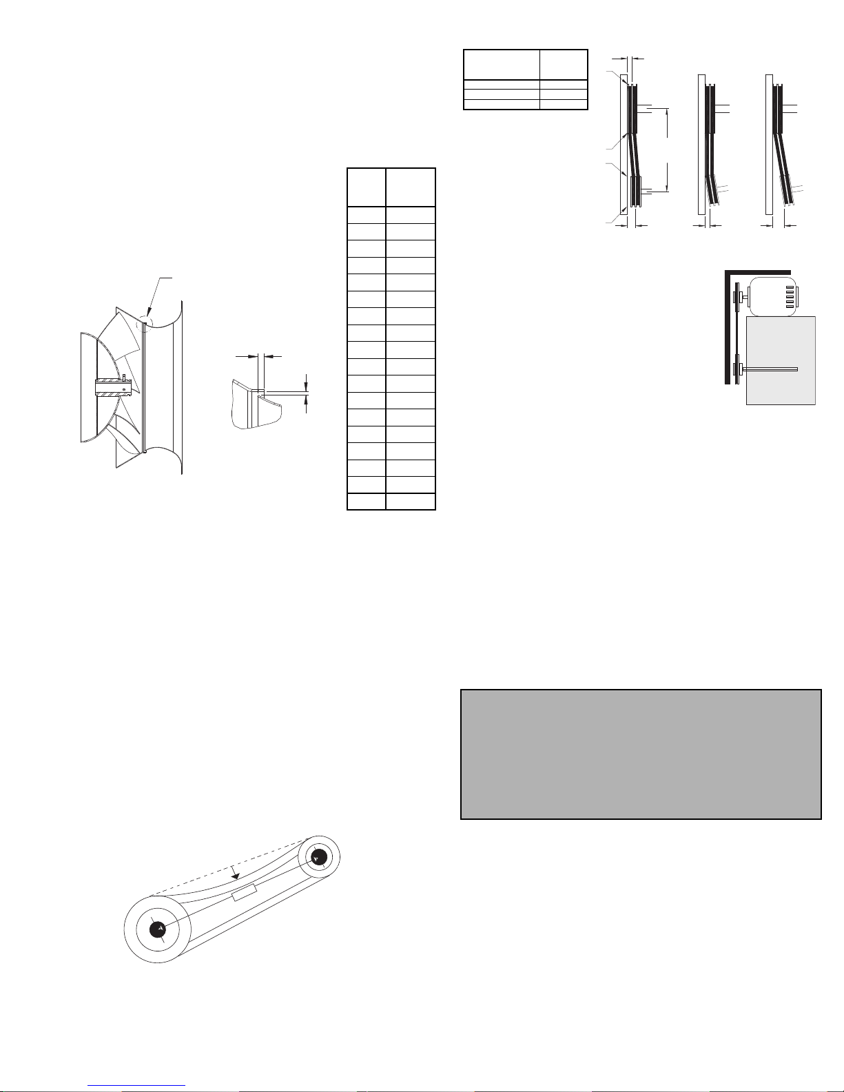
Wheel-to-Inlet Clearance
1 foot
1/4 inch
The correct wheel-to-inlet clearance is critical to proper
fan performance. This clearance should be verified before
initial start-up since rough handling during shipment could
cause a shift in fan components. Refer to wheel/inlet drawing below for correct overlap.
Adjust the overlap by loosening the wheel hub and moving the wheel along the shaft to obtain the
correct value. Trim balance as necessary
following procedure (.0785 in/sec max).
A uniform radial gap (space between the
edge of the cone and the edge of the inlet) is
obtained by loosening the inlet cone bolts
and repositioning the inlet cone.
SEE DETAIL A
OVERLAP
RADIAL GAP
DETAIL A
Wheel/Inlet Overlap
Unit
Overlap
Size
(Inches)
90 0.16
120 0.19
135 0.20
150 0.22
165 0.23
180 0.24
202 0.27
225 0.29
245 0.31
270 0.33
300 0.37
330 0.41
365 0.45
402 0.50
445 0.55
490 0.61
540 0.67
600 0.76
Belt and Pulley Installation
Belt tension is determined by the sound the belts make
when the fan is first started. Belts will produce a loud squeal
which dissipates after the fan is operating at full capacity. If
the belt tension is too tight or too loose, lost efficiency and
possible damage can occur.
Do not change the pulley pitch diameter to change
tension. This will result in a different fan speed.
a. Loosen motor plate adjustment bolts and move motor
plate in order that the belts can easily slip into the
grooves on the pulleys. Never pry, roll, or force the
belts over the rim of the pulley.
b. Adjust the motor plate until proper tension is reached.
For proper tension, a deflection of approximately 1/4”
per foot of center distance should be obtained by firmly
pressing the belt. Refer to Figure 3.
c. Lock the motor plate adjustment nuts in place.
d. Ensure pulleys are properly aligned. Refer to Figure 4.
Tolerance
Center Distance
Up thru 12” 1/16”
12” up through 48 1/8”
Over 48” 1/4”
Figure 4
Maximum
Gap
OFFSET ANGULAR OFFSET/ANGULAR
A
W
B
CENTER
DISTANCE
(CD)
GAP
X
Y
Z
GAP
Figure 4 indicates where to measure
the allowable gap for the drive alignment
tolerance. All contact points (indicated by
WXYZ) are to have a gap less than the
tolerance shown in the table. When the
pulleys are not the same width, the allowable gap must be adjusted by half of the
difference in width. Figure 5 illustrates
using a carpenter’s square to adjust the
position of the motor pulley until the belt is
parallel to the longer leg of the square.
Figure 5
Wiring Installation
All wiring should be in accordance with local ordinances
and the National Electrical Code, NFPA 70. Ensure the
power supply (voltage, frequency, and current carrying
capacity of wires) is in accordance with the motor nameplate.
Lock off all power sources before unit is wired to
power source.
Leave enough slack in the wiring to allow for motor
movement when adjusting belt tension. Some fractional
motors have to be removed in order to make the connection with the terminal box at the end of the motor. To
remove motor, remove bolts securing motor base to power
assembly. Do not remove motor mounting bolts.
Personal Safety
Disconnect switches are recommended. Place the
disconnect switch near the fan in order that the
power can be swiftly cut off in case of an
emergency, and in order that maintenance
personnel are provided complete control of the
power source.
Follow the wiring diagram in the disconnect switch
and the wiring diagram provided with the motor. Correctly label the circuit on the main power box and
always identify a closed switch to promote safety (i.e.,
red tape over a closed switch).
Figure 3
Pulley Alignment
Pulley alignment is adjusted by loosening the motor pulley
setscrew and by moving the motor pulley on the motor shaft.
3
Page 5
Use of Variable Frequency Drives
Motors -
Motors that are to be operated using a Variable Frequency Drive (VFD) must be VFD compatible. At a minimum, this must be a Premium Efficiency motor with Class F
insulation. Motors that are not supplied by Loren Cook
Company should have the recommendation of the motor
manufacturer for use with a VFD.
Grounding -
The fan frame, motor and VFD must be connected to a
common earth ground to prevent transient voltages from
damaging rotating elements.
Wiring -
Line reactors may be required to reduce over-voltage
spikes in the motors. The motor manufacturer should be
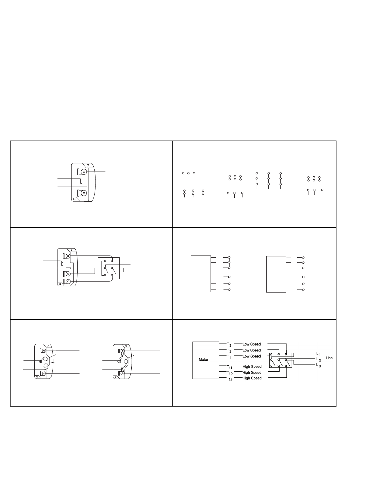
Wiring Diagrams
consulted for recommended line impedance and usage of
line reactors or filters, if the lead length between the VFD
and the motor exceeds 10 feet (3m).
Fan -
It is the responsibility of the installing body to perform
coast-down tests and identify any resonant frequencies
after the equipment is fully installed. These resonant frequencies are to be removed from the operating range of
the fan by using the “skip frequency” function in the VFD
programming. Failure to remove resonant frequencies
from the operating range will decrease the operating life of
the fan and void the warranty.
Single Speed, Single Phase Motor
Ground A
L
1
T-1
T-4
Line
L
2
Ground B
When ground is required, attach to ground A or B with No. 6 thread forming
screw. To reverse, interchange T-1 and T-4.
2 Speed, 2 Winding, Single Phase Motor
Ground A
High Speed
T-1
T-4
Ground B
When ground required, attach to ground A or B with No. 6 thread forming
screw. To reverse, interchange T-1 and T-4 leads.
Low Speed
L
1
Line
L
2
3 Phase, 9 Lead Motor
Y-Connection
Low Voltage
208/230 Volts
4
5
6
1
728
To reverse, interchange any 2 line leads.
3
9
L2L
L
3
1
High Voltage
460 Volts
456
789
12
L2L
L
1
3 Phase, 9 Lead Motor
Delta-Connection
Low Voltage
208/230 Volts
8
7
4
6
2
1
3
L
1
3
L
L
2
High Voltage
9
5
3
3
460 Volts
789
456
12
L
L
1
2
3
L
3
2 Speed, 1 Winding, 3 Phase Motor
High Speed
1
Together
2
Motor
To reverse, interchange any 2 line leads. Motors require magnetic control.
3
L
4
1
L
5
2
6
Line
L
3
Low Speed
Motor
L
1
1
L
2
2
L
3
Open
Line
3
4
5
6
Single Speed, Single Phase, Dual Voltage 2 Speed, 2 Winding, 3 Phase
Ground A
L
Line
L
1
T-5
J-10
2
Ground B
T-5
J-10
Ground B
When ground required, attach to ground A or B with No. 6 thread forming
screw. To reverse, interchange T-5 and J-10 leads.
Link A
Link B
Low Voltage
Ground A
Link A & B
L
1
Line
L
2
To reverse: High Speed-interchange leads T11 and T12.
Low Speed-interchange leads T1 and T2. Both Speeds-interchange any 2
line leads.
4
Page 6
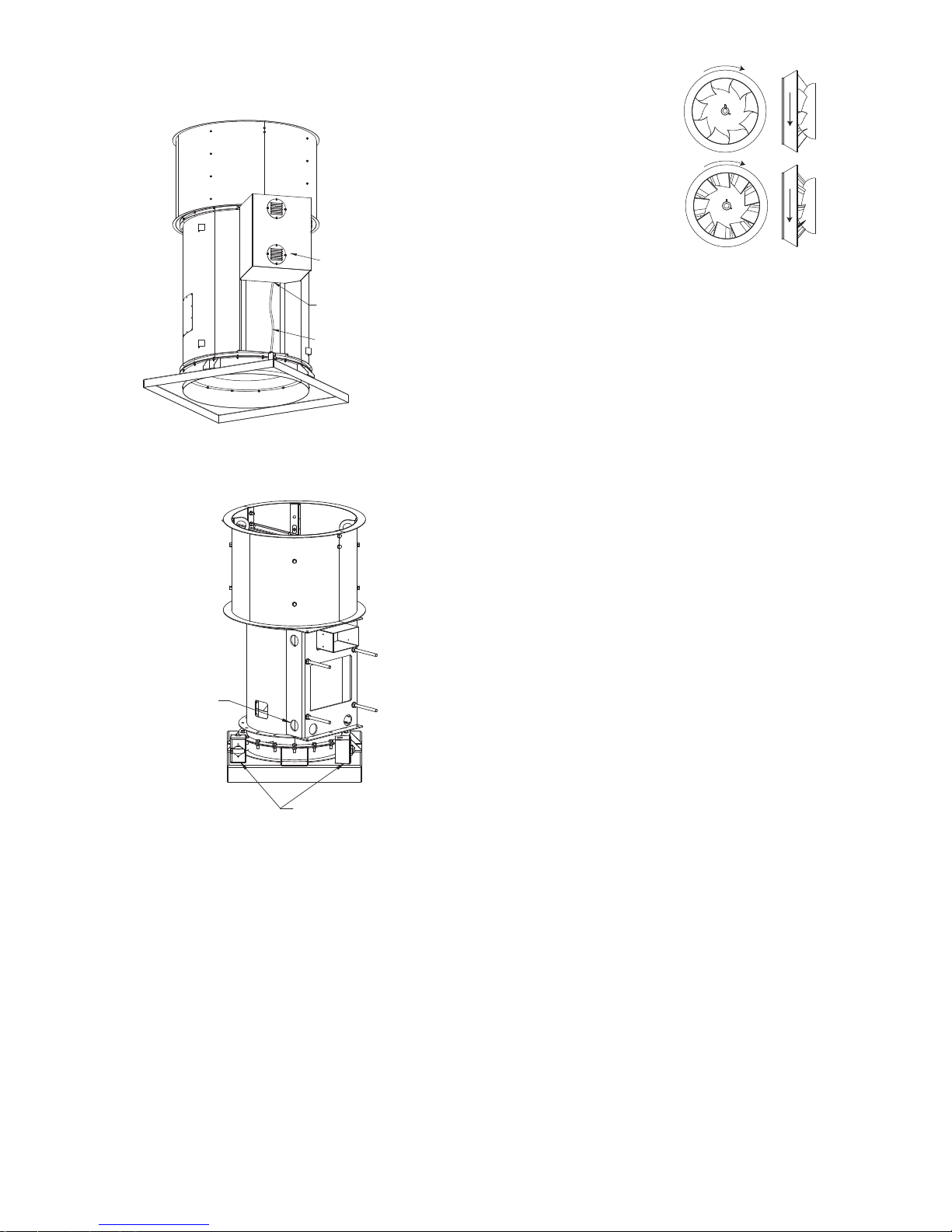
Typical Wiring Path for Roof Mounted Units
For sizes 135-600, route conduit under motor cover
between the motor support rails and out to enclosure as
shown in Figure 1 below.
Figure 1
ble to interchange two leads at this location so that the
fan is operating in the correct direction.
QMX
QMX-HP
Size 135-600, Run
Liquidtite Between
Weather Cover and Unit
Liquidtite
For sizes 90-120, route conduit through holes in the
sides of the motor support saddle as shown in Figure 2
below.
Figure 2
90-120, Run
Liquidtite Through
Holes in Saddle
Enclosure May Be Located
in Either Corner
(Liquidtite Not Shown)
Wheel Rotation
Test the fan to ensure the rotation of the wheel is the
same as indicated by the arrow marked Rotation.
115 and 230 Single Phase Motors
Fan wheel rotation is set correctly at the factory. Changing the rotation of this type of motor should only be
attempted by a qualified electrician.
208, 230, and 460, 3 Phase Motors
These motors are electrically reversible by switching
two of the supply leads. For this reason, the rotation of the
fan cannot be restricted to one direction at the factory. See
Wiring Diagrams for specific information on reversing
wheel direction.
Do not allow the fan to run in the wrong direction.
This will overheat the motor and cause serious damage. For 3-phase motors, if the fan is running in the
wrong direction, check the control switch. It is possi-
Weather Cover
Final Installation Steps
a. Inspect fasteners and setscrews, particularly fan
mounting and bearing fasteners, and tighten according to the recommended torque shown in the table
Recommended Torque for Setscrews/Bolts.
b. Inspect for correct voltage with voltmeter.
c. Ensure all accessories are installed.
Operation
Pre-Start Checks
a. Lock out all the primary and secondary power
sources.
b. Ensure fasteners and setscrews, particularly those
used for mounting the fan, are tightened.
c. Inspect belt tension and pulley alignment.
d. Inspect motor wiring.
e. Ensure belt touches only the pulley.
f. Ensure fan and ductwork are clean and free of debris.
g. Inspect wheel-to-inlet clearance. The correct wheel-
to-inlet clearance is critical to proper fan performance.
h. Close and secure all access doors.
g. Restore power to the fan.
Start Up
Turn the fan on. In variable speed units, set the fan to its
lowest speed and inspect for the following:
• Direction of rotation.
• Excessive vibration.
• Unusual noise.
• Bearing noise.
• Improper belt alignment or tension (listen for squealing).
• Improper motor amperage or voltage.
If a problem is discovered, immediately shut the fan
off. Lock out all electrical power and check for the
cause of the trouble. See Troubleshooting.
Inspection
Inspection of the fan should be conducted at the first 30
minute, 8 hour and 24 hour intervals of satisfactory opera-
tion. During the inspections, stop the fan and inspect as per
the Conditions Chart.
30 Minute Interval
Inspect bolts, setscrews, and motor mounting bolts.
Adjust and tighten as necessary.
8 Hour Interval
Inspect belt alignment and tension. Adjust and tighten as
necessary.
24 Hour Interval
Inspect belt tension. Adjust and tighten as necessary.
5
Page 7
Recommended Torque for Setscrews/Bolts
Setscrews
Size
No.10 3/32” 28 33 3/8”-16 240
1/4” 1/8” 66 80 1/2”-13 600
5/16” 5/32” 126 156 5/8”-11 1200
3/8” 3/16” 228 275 3/4”-10 2100
7/16” 7/32” 29 348 7/8”-9 2400
1/2” 1/4” 42 504 1” -8 3000
5/8” 5/16” 92 1104
3/4” 3/8” 120 1440
Key Hex
Across
Flats
Recommended
Torque
Min. Max. Size
(IN/LB)
Hold Down Bolts
Wrench
Torque
Maintenance
Establish a schedule for inspecting all parts of the fan.
The frequency of inspection depends on the operating conditions and location of the fan.
Inspect fans exhausting corrosive or contaminated air
within the first month of operation. Fans exhausting contaminated air (airborne abrasives) should be inspected
every three months.
Regular inspections are recommended for fans exhausting non-contaminated air.
It is recommended the following inspection be conducted
twice per year.
• Inspect bolts and setscrews for tightness. Tighten as
necessary.
• Inspect belt wear and alignment. Replace worn belts
with new belts and adjust alignment as needed. Refer
to Belt and Pulley Installation, page 3.
• Bearings should be inspected as recommended in the
Conditions Chart.
• Inspect variable inlet vanes (if supplied) for freedom of
operation and excessive wear. The vane position
should agree with the position of the control arm. As
the variable inlet vanes close, the entering air should
spin in the same direction as the wheel.
• Inspect springs and rubber isolators for deterioration
and replace as needed.
• Inspect for cleanliness. Clean exterior surfaces only.
Removing dust and grease on motor housing assures
proper motor cooling. Removing dirt from the wheel
and housing prevents imbalance and damage.
Lubrication - Fan Bearings
QMX bearings are lubricated through a grease fitting on
the outer housing and should be lubricated by the schedule, Conditions Chart.
For best results, lubricate the bearing while the fan is in
operation. Pump grease in slowly until a slight bead forms
around the bearing seals. Excessive grease can burst
seals thus reducing bearing life.
Lubrication Conditions Chart
Fan Class Fan Status Shaft Size
Normal Conditions
(Clean, Dry & Smooth)
QMX
QMX-HP
Extreme Conditions
(Dirty/Wet/Rough)
Normal Conditions
(Clean, Dry & Smooth)
Extreme Conditions
(Dirty/Wet/Rough)
> 1-1/2” 7,500
< 1-1/2” 2,000
> 1-1/2” 1,500
< 1-1/2” 400
> 2” 5,000
< 2” 1,000
> 2” 1,000
< 2” 200
Maximum Interval (opera-
tional hrs)
In the event the bearing cannot be seen, use no more than
three injections with a hand-operated grease gun.
Before lubricating, the grease nipple and immediate
vicinity should be thoroughly cleaned without the use of
high pressure equipment. The grease should be supplied
slowly as the bearing rotates until fresh grease slips past
the seal. Excessive pressure should be avoided to prevent
seal damage.
Exceptions to the greasing interval chart:
• Periodic Applications (any break of one week or
more): it is recommended that full lubrication be performed
prior to each break in operation.
• Higher Temperature: it is recommended to halve the
intervals for every 30F increase in operating temperature
above 120F not to exceed 230F for standard bearings;
High Temperature bearings (optional) can operate up to
400F.
• Vertical Shaft: it is recommended that the intervals
should be halved.
Loren Cook Company uses petroleum lubricant in a lithium base. Other types of grease should not be used unless
the bearings and lines have been flushed clean. If another
type of grease is used, it should be a lithium-based grease
conforming to NLGI grade 2 consistency.
A NLGI grade 2 grease is a light viscosity, low-torque,
rust-inhibiting lubricant that is water resistant. Its temperature range is from -30F to +200F and capable of intermittent highs of +250F.
Lubrication - Motor Bearings
Motors are provided with prelubricated bearings. Any
lubrication instructions shown on the motor nameplate
supersede instructions below.
Motor bearings without provisions for relubrication will
operate up to 10 years under normal conditions with no
maintenance. In severe applications, high temperatures or
excessive contaminates, it is advisable to have the maintenance department disassemble and lubricate the bearings
after 3 years of operation to prevent interruption of service.
For motors with provisions for relubrication, follow intervals of the table below.
Relubrication Intervals
NEMA Frame Size
Service
Conditions
Standard 3 yrs. 6 months 2 yrs. 6 months 1 yr. 3 months
Severe 1 yr. 3 months 1 yr. 3 months 6 months 1 months
Up to and
including 184T
1800 RPM
and less
Over 1800
RPM
213T-365T 404T and larger
1800 RPM
and less
Over 1800
RPM
1800 RPM
and less
Over 1800
RPM
Motors are provided with a polyurea mineral oil NGLI #2
grease. All additions to the motor bearings are to be with a
compatible grease such as Exxon Mobil Polyrex EM and
Chevron SRI.
The above intervals should be reduced to half for vertical
shaft installations.
Motor Services
Should the motor prove defective within a one-year
period, contact your local Loren Cook representative or
your nearest authorized electric motor service representative.
6
Page 8
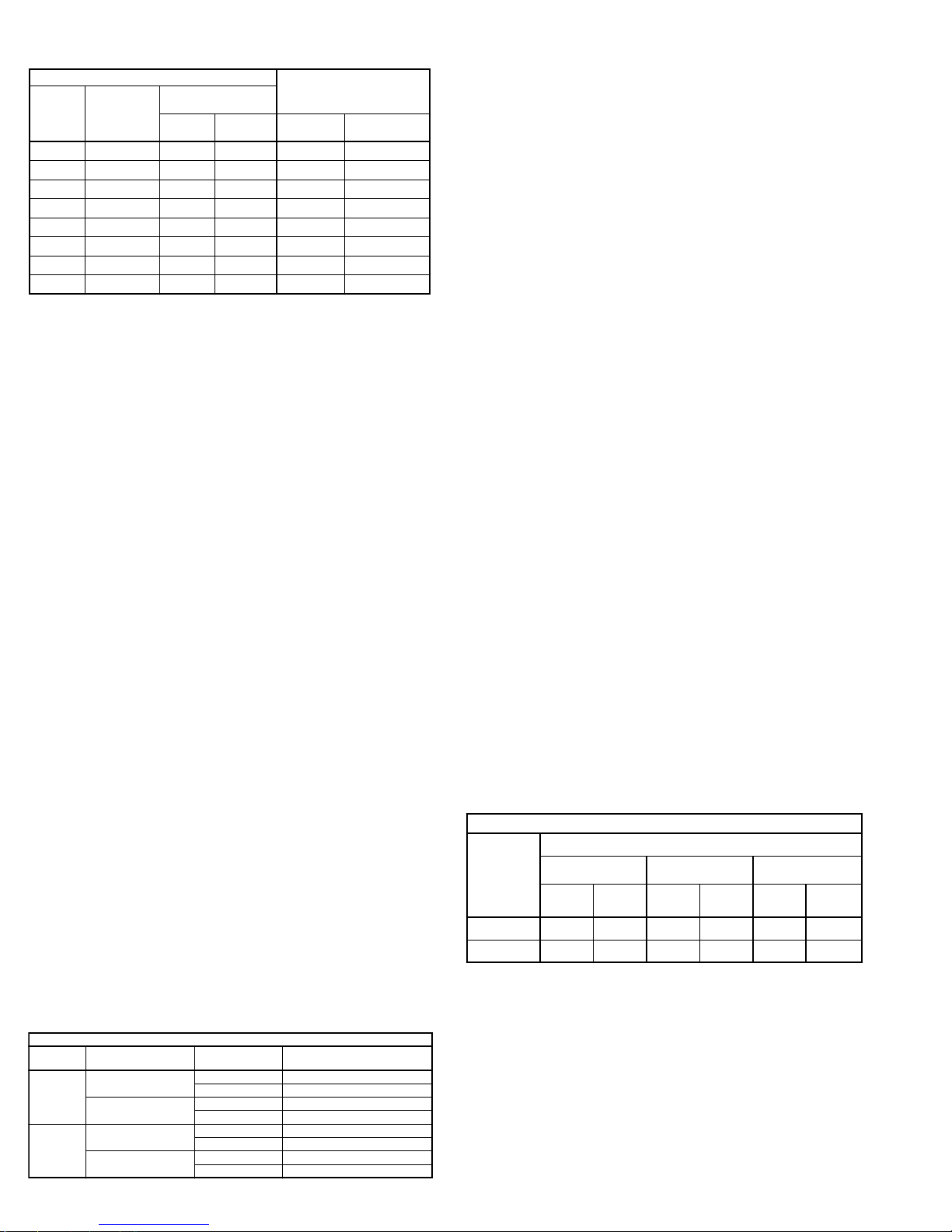
Changing Shaft Speed
All belt driven fans with motors up to and including 5 HP
are equipped with variable pitch pulleys. To change the fan
speed, perform the following:
a. Loosen setscrew on driver (motor) pulley and remove
key, if equipped.
If the pulley has multiple grooves, all must be adjusted
to the same width.
c. After adjustment, inspect for proper belt tension.
Speed Reduction
Open the pulley in order that the belt rides deeper in
the groove (smaller pitch diameter).
Speed Increase
Close the pulley in order that the belt rides higher in
the groove (larger pitch diameter). Ensure that the
speed limits of the fan and the horsepower limits of the
motor are maintained.
Max Catalog RPM
Pulley and Belt
Replacement
a. Loosen and remove belts
by adjusting motor
mounting plate.
b. Remove pulleys from
their respective shafts.
c. Clean the motor and fan
shafts.
d. Clean bores of pulleys
and coat the bores with
heavy oil.
e. Remove grease, rust, or
burrs from the pulleys
and shafts.
Fan
Size
120 3707 4490
135 3295 3991
150 2907 3510
165 2633 3191
180 2423 2925
202 2152 2600
225 1937 2340
245 1780 2149
270 1623 1866
300 1465 1679
330 1332 1527
365 1207 1381
402 1081 1252
445 988 1132
490 897 1028
540 813 933
600 732 -
QMX QMX-HP
90 4943 5987
f. Remove burrs from shaft by sanding.
g. Place fan pulley on fan shaft and motor pulley on its
shaft. Damage to the pulleys can occur when excessive force is used in placing the pulleys on their
respective shafts.
h. Tighten in place.
i. Install belts on pulleys and align as described in the
Belt and Pulley Installation section.
Bearing Replacement
The fan bearings are pillow block ball bearings.
a. Loosen and remove belts by adjusting motor mounting
plate
b. Remove the bearing cover by removing the bolts
around the perimeter of the bearing cover. Do not
remove fan sheave yet.
c. Remove inlet cone by removing attaching bolts/nuts
around perimeter of the inlet plate.
d. Remove wheel by loosening setscrews and sliding off
shaft.
e. Record the location of the fan sheave from end of
shaft, and remove the sheave.
f. Record the distance from the bearing to the end of the
shaft.
g. Loosen setscrews on bearings and remove shaft.
j. Remove bearings from bearing base and replace with
new ones, noting the exact location of each; do not
fully tighten base bolts.
k. Slide shaft through bearings until shaft protrudes the
same amount as measured above. Tapping the inner
race of each bearing with a soft driver may be
required. Do not hammer the end of the shaft or the
bearing housing.
l. Return setscrews to same location as marked above
and tighten one setscrew on each bearing to half its
specified torque.
m. Rotate the shaft to allow the bearings to align them
selves.
n. Replace wheel but do not tighten yet.
o. Replace inlet cone. Wheel may need to be moved to
allow proper alignment. Care should be taken to
insure that inlet cone is centered inside wheel before
and after tightening attaching bolts.
p. Slide wheel on shaft to achieve proper wheel/inlet
overlap and tighten wheel set screws. Refer to
Wheel-to-Inlet Clearance on page 3.
q. Tighten hold-down bolts to proper torque.
r. Turn the shaft by hand. resistance should be the
same as it was before hold-down bolts were fully tight-
ened.
s. Tighten all bearing setscrews to full specified torque.
t. Replace the sheave, align with motor sheave, and
adjust the belt tension.
u. Test run fan and retighten all setscrews and bolts, and
trim balance as necessary (.0785 in/sec max).
v. Replace discharge cover.
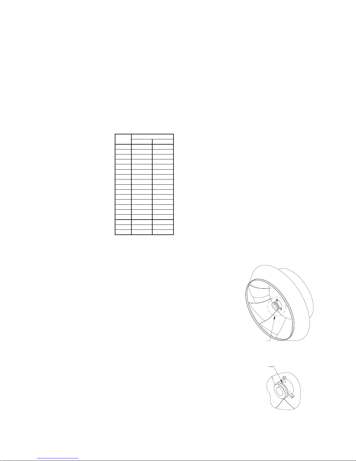
Wheel Replacement
The wheel has a pre-machined shoulder in the hub for
the use of most 2 and 3 jaw mechanical puller.
a. Align center of the puller with the center of the shaft.
b. Ensure all setscrews in the hub, normally two, are
fully removed.
c. Slowly remove wheel from the shaft.
SEE DETAIL A
PRE-MACHINED SHOULDER
DETAIL A
7
Page 9
Troubleshooting
Problem and Potential Cause
Low Capacity or Pressure
•Incorrect direction of rotation. Make sure the fan rotates in same direction as the arrows on the motor or belt
drive assembly.
•Poor fan inlet or outlet conditions. There should be a straight clear duct at the inlet or outlet.
•Improper wheel alignment.
Excessive Vibration and Noise
•Damaged wheel.
•Belts misaligned.
•Belts too loose; worn or oily belts.
•Loose fasteners.
•Speed too high.
•Incorrect direction of rotation. Make sure the fan rotates in same direction as the arrows on the motor or belt
drive assembly.
•Bearing set screws loose.
•Bearings need lubrication or replacement.
•Debris in impeller.
•Fan surge.
•See page 4 for issues regarding use of VFD.
Overheated Motor
•Motor improperly wired.
•Incorrect direction of rotation. Make sure the fan rotates in same direction as the arrows on the motor or belt
drive assembly.
•Cooling air diverted or blocked.
•Improper inlet clearance.
•Incorrect fan speed.
•Incorrect voltage.
Overheated Bearings
•Improper bearing lubrication
•Excessive belt tension.
8
Page 10
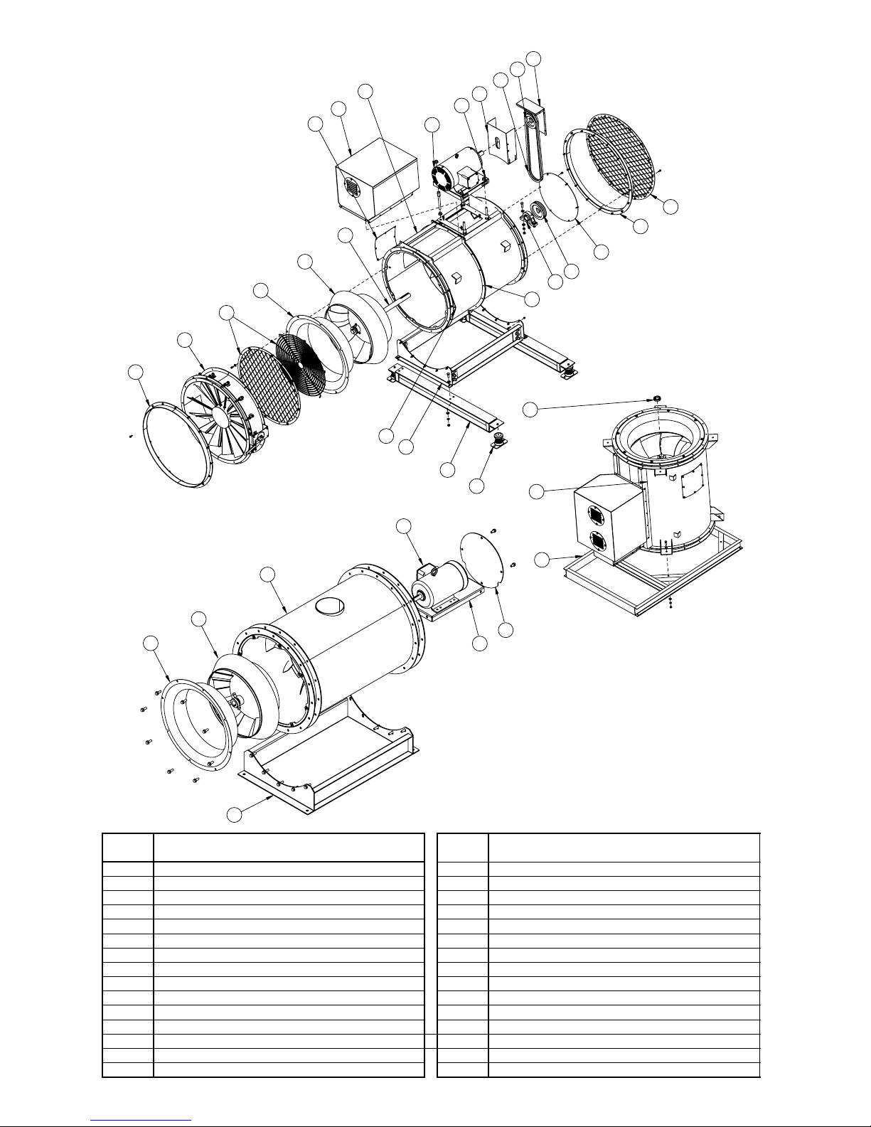
QMX/QMXD-HP/QMX-HP Parts List
8
7
6
5
4
3
2
1
Horizontal Mount
12
14
9
10
21
20
19
13
12
11
15
1
16
14
17
30
24
18
23
10
22
25
29
4
Direct Drive
ITEM
NUMBER
1 Companion Flange (Optional) 16 Bearing Cover
2 External Inlet Vane Damper (Optional) 17 Bearings (Two Required)
3 Inlet Spiral Guard or Safety Screen (Optional) 18 Isolator (Four Required Optional)
4 Inlet Cone 19 Isolation Rails - Horizontal Mount (Optional)
5 Mix-Flow Wheel 20 Base - Horizontal Mount (QMX)
6 Shaft 21 Thrust Restraint - Horizontal Mount (Optional)
7 Access Door (Optional) 22 Isolation Structure - Vertical Mount (Optional)
8 Motor Cover (Optional) 23 Housing - Vertical Mount (QMX)
9 Housing-Horizontal Mount (QMX) 24 Shaft Locking Collar - Vertical Mount
10 Motor 25 Housing - Direct Drive
11 Motor Plate (QMX) 26 Base - Direct Drive
12 Belt Guard 27 Motor Plate - Direct Drive
13 Belt Set 28 Motor Cover - Direct Drive
14 Drive Pulley 29 Mix-Flow Wheel - Direct Drive
15 Discharge Safety Screen (Optional) 30 Horizontal Split Housing (Optional)
26
DESCRIPTION
ITEM
ITEM
NUMBER
27
28
ITEM
DESCRIPTION
Vertical Mount
9
Page 11
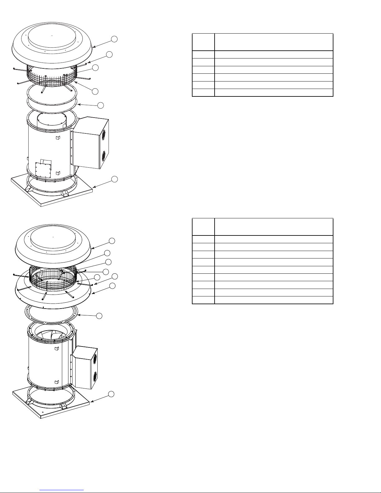
QMXE/QMXE-HP Parts List
3
2
5
QMXS/QMXS-HP Parts List
5
9
6
4
ITEM
NUMBER
1 QMX Curb Cap
2 QMXE Birdscreen
3 QMXE Top Cap Post
4 QMXE Baffle Brace
5 QMXE Top Cap Extension (for Size 90 only)
6 QMXE Top Cap
See common parts (not shown) listed on page 9.
ITEM
DESCRIPTION
1
ITEM
NUMBER
6
7
8
4
3
2
1 QMX Curb Cap
2 QMXS Top Cap-Open
3 QMXS Upper Baffle Brace
4 QMXS Top Cap Post
5 QMXS Birdscreen
6 QMXS Top Cap
7 QMXS Lower Top Cap Post
8 QMXS Lower Baffle Brace
9 QMXS Adapter Plate
See common parts (not shown) listed on page 9.
ITEM
DESCRIPTION
1
10
Page 12

QMXU/QMXU-HP Parts List
6
5
4
2
3
ITEM
NUMBER
ITEM
DESCRIPTION
1 QMX Curb Cap
2 QMXU Lifting Lug
3 QMXU Damper
4 QMXU Damper Stop
5 QMXU Windband
6 QMXU Discharge Guard (Optional)
See common parts (not shown) listed on page 9.
1
QMXLE/QMXLE-HP Parts List
7
6
5
4
3
ITEM
NUMBER
ITEM
DESCRIPTION
1 QMXLE Mixing Box
2 QMXLE Curb Cap
3 QMXLE Middle Section
4 QMXLE Adapter Plate
5 QMXLE Stack Damper
6 QMXLE Windband
7 QMXLE Lifting Lug
See common parts (not shown) listed on page 9.
2
1
11
Page 13

Arrangement 3 Parts List
6
1
3
2
5
4
ITEM
NUMBER
1 Arr. 3 Bearing Support
2 Arr. 3 Shaft
3 Arr. 3 Spiral Guard
4 Arr. 3 Base
5 Arr. 3 Housing
6 Arr. 3 Motor Cover
See common parts (not shown) listed on page 9.
Limited Warranty
Loren Cook Company warrants that your Loren Cook fan was manufactured free of defects in materials and workmanship, to the extent stated herein. For a period of one (1)
year after date of shipment, we will replace any parts found to be defective without charge, except for shipping costs which will be paid by you.
This warranty is granted only to the original purchaser placing the fan in service.
This warranty is void if the fan or any part thereof has been altered or modified from its original design or has been abused, misused, damaged or is in worn condition or if the
fan has been used other than for the uses described in the company manual. This warranty does not cover defects resulting from normal wear and tear.
To make a warranty claim, notify Loren Cook Company, General Offices, 2015 East Dale Street, Springfield, Missouri 65803-4637, explaining in writing, in detail, your complaint and referring to the specific model and serial numbers of your fan. Upon receipt by Loren Cook Company of your written complaint, you will be notified, within thirty
(30) days of our receipt of your complaint, in writing, as to the manner in which your claim will be handled. If you are entitled to warranty relief, a warranty adjustment will be
completed within sixty (60) business days of the receipt of your written complaint by Loren Cook Company.
This warranty gives only the original purchaser placing the fan in service specifically the right. You may have other legal rights which vary from state to state.
For fans provided with motors, the motor manufacturer warrants motors for a designated period stated in the manufacturer’s warranty. Warranty periods vary from manufacturer to manufacturer. Should motors furnished by Loren Cook Company prove defective during the designated period, they should be returned to the nearest authorized
motor service station. Loren Cook Company will not be responsible for any removal or installation costs.
ITEM
DESCRIPTION
Corporate Offices: 2015 E. Dale Street Springfield, MO 65803 417.869.6474
lorencook.com
12
QMX IOM - Oct 2012
Page 14

®
AC / VCR
Centrifugal Roof & Wall exhausters
Installation, Operation, and Maintenance Manual
This publication contains the installation, operation and
maintenance procedures for standard units of the AC &
VCR: Centrifugal Roof and Wall Exhausters.
Carefully read this publication and any
supplemental documents prior to any
installation or maintenance procedure.
Loren Cook Company’s AC catalog & VCR catalog
provide additional information describing the equipment,
fan performance, available accessories and specication
data.
For additional safety information, refer to AMCA
publication 410-96, Safety Practices for Users and
Installers of Industrial and Commercial Fans.
All of the publications listed above can be obtained
from Loren Cook Company by phoning (417) 869-6474,
extension 166; by FAX at (417) 832-9431; or by e-mail at
info@lorencook.com.
For information and instructions on special equipment,
contact Loren Cook Company at (417) 869-6474.
Rotating Parts & Electrical Shock Hazard:
Fans should be installed and serviced by qualied personnel
only.
Disconnect electric power before working on unit (prior to
removal of guards or entry into access doors).
Follow proper lockout / tagout procedures to ensure the unit
cannot be energized while being installed or serviced.
A disconnect switch should be placed near the fan in order that
the power can be swiftly cut off, in case of an emergency and in
order that maintenance personnel are provided complete control
of the power source.
Grounding is required. All eld-installed wiring must be
completed by qualied personnel. All eld installed wiring must
comply with National Electric Code (NFPA 70) and all applicable
local codes.
Fans and blowers create pressure at the discharge and vacuum
at the inlet. This may cause objects to get pulled into the unit
and objects to be propelled rapidly from the discharge. The
discharge should always be directed in a safe direction and inlets
should not be left unguarded. Any object pulled into the inlet will
become a projectile capable of causing serious injury or death.
When air is allowed to move through a non-powered fan,
the impeller can rotate, which is referred to as windmilling.
Windmilling will cause hazardous conditions due to unexpected
rotation of components. Impellers should be blocked in position
or air passages blocked to prevent draft when working on fans.
Friction and power loss inside rotating components will cause
them to be a potential burn hazard. All components should be
approached with caution and/or allowed to cool before contacting
them for maintenance.
Under certain lighting conditions, rotating components may
appear stationary. Components should be veried to be
stationary in a safe manner, before they come into contact with
personnel, tools or clothing.
Failure to follow these instructions could result in death or
serious injury.
Receiving and Inspection
Carefully inspect the fan and accessories for any
damage and shortage immediately upon receipt of fan.
• Turn the wheel by hand to ensure it turns freely and
does not bind.
• Inspect dampers (if included) for free operation of
all moving parts.
• Record on the Delivery Receipt any visible sign of
damage.
Handling
Lift the fan by the lifting
lugs provided under top cap.
NOTICE! Never lift by the shaft,
motor or housing.
Storage
If the fan is stored for any
length of time prior to installation,
store it in its original shipping
crate and protect it from dust,
debris and the weather.
Installation
Code Requirements & Environmental Effects
The attachment of roof mounted fans to the roof curb as well
as the attachment of roof curbs to the building structure must
exceed the structural requirements based on the environmental
loading derived from the applicable building code for the
site. The local code ofcial may require variations from the
recognized code based on local data. The licensed engineer of
record will be responsible for prescribing the correct attachment
based on construction materials, code requirements and
environmental effects specic to the installation.
Failure to follow these instructions could result in death or
serious injury.
ACE
Lifting lugs
ACW
ACRU,
ACSC & VCR
:
AC/VCR IO&M B51003-001
1
Page 15

If the fan was delivered with the motor unmounted, see
Conduit for
Conduit for
Control)
the maintenance sections for belt and pulley installation.
Downblast
Wall Exhausters
If the fan is a wall mount unit and a grease terminator
or grease trough was not purchased, a 1-1/16 inch
diameter drain hole should be inserted on the bottom side
of the unit for drainage.
If your fan is a wall exhauster with a round base, a
mounting template is shipped with the fan. Use the
template to locate the necessary lag screws or anchor
bolts on the wall. The fan can then be lifted and attached
easily. Secure with lag screws, anchor bolts, or other
suitable fasteners.
Topcap
Wires
Motor
WheelBaffle
VCR Installation
A. Ensure the fan discharge is a minimum 40 inches
above the roof the roof surface and a minimum of 10 foot
from any building air intake in order to comply with NFPA
96.
B. Minimum exhaust velocity in the duct should be 1500
FPM in accordance with NFPA 96.
C. If the fan is installed on a surface that is not level,
install the fan in a position that places the drain tube at
the lowest position.
D. Secure the fan to the roof curb at all four corners
using a minimum of four anchor bolts, lag screws or other
suitable fastener.
Inlet
Upblast
Topcap
Wires
Vent Tube
Conduit
junction
(used for
grease)
Damper Installation
If your fan is supplied with dampers, follow the
directions below.
• Place the damper inside the curb or inside the duct
Baffle
work. Ensure the damper will open freely for the correct
direction of the airow.
• Secure to curb at the damper shelf.
• Drill hole in the curb shelf for conduit needed for motor
wiring.
• Operate the dampers manually to ensure the blades
move freely.
• Install fan over curb while aligning the conduit location
with the conduit hole in the curb.
compartment of the unit for ACE, ACRU and ACW units.
The motor’s wiring box may be on the side of the motor,
the shaft end of the motor or the opposite shaft end of the
motor. If an additional eld wiring compartment is added,
Smoke control
Use of any backdraf t dampers is not permitted. Fire dampers
and/or smoke dampers may be required in a smoke control
system. These dampers must meet the requirements determined
by the local code authority.
:
then an approved metal box with cover must be secured
to the unit with two screws in order that the box does not
rotate. All wiring must be protected from abrasion where
they enter and exit. The ground wire must be secured
under the green ground screw within the eld wiring
compartment. See motor wiring diagram, NEC and local
Wiring
NOTICE! All wiring should be in accordance
with local ordinances and the National
Electrical Code, NFPA 70. Ensure the power
supply (voltage, frequency, and current
carrying capacity of wires) is in accordance
with the motor nameplate.
ACRU Upblast units have two wiring conduits. The
horizontal conduit is directly above the vertical conduit.
code for additional details.
For VCR and ACSC units a separate NEMA 3 eld
wiring compartment is provided on the exterior of the unit.
For further information refer to the National Electrical
Code and the wiring diagram provided on the motor.
Leave enough slack in the wiring to allow for motor
movement when adjusting belt tension. Some fractional
motors have to be removed in order to make the
connection with the terminal box at the end of the motor.
ACE downblast units have a single vertical conduit.
The motor’s wiring box is the approved eld wiring
AC/VCR IO&M B51003-001
2
Motor
Wheel
Inlet
Conduit
junction
(used for
Smoke
Page 16

NOTICE! Follow the wiring diagram in the
T-
T-
Ground B
Ground A
Line
Ground A
Ground B
T-
T-
Line
Ground B
J-10
Ground A
Ground A
Line
1
3
oltage
3 Phase, 9 Lead Motor
Y-
208/230 V
oltage
1
3
2
3 Phase, 9 Lead Motor
Motor
Tr
*
L3
Black (High)
White Line
White Line
Black Line
disconnect switch and the wiring diagram
provided with the motor. Correctly label the
circuit on the main power box and always
identify a closed switch to promote safety (i.e.,
red tape over a closed switch).
1. Remove the top cap which covers the motor assembly
by unlatching the snap clips.
2. For internal wiring, run the electrical wire and conduit
through the opening drilled in the damper shelf (refer
to Damper Installation), then through the wiring conduit
in the ventilator base to the motor compartment. For
external wiring, run the wires through the horizontal
conduit on upblast units, or under top cap in downblast
units.
3. Pull the wires through and complete the wiring.
Use the following diagrams to wire the motor except
for EC and EC/PM wiring diagrams, see additional
supplement.
Single Speed, Single Phase Motor
When ground is required, attach
L
1
4
L
to ground A or B with no. 6
1
thread forming screw. To reverse,
interchange T-1 and T-4.
2
2 Speed, 2 Winding, 3 Phase
To reverse: High Speed-interchange leads T11 and T12.
Low Speed-interchange leads T1 and T2. Both Speedsinterchange any 2 line leads.
Second
Damper
+
L2
L1
Transformer*
Typical Damper Motor Schematic
Fan
Motor
ansformer**
Damper
Motor*
For 3 phase, damper motor voltage should be the same
between L1 and L2. For single phase application, disregard
L3. *Damper motors may be available in 115, 230 and 460 volt
models. The damper motor nameplate voltage should be veried
prior to connection. ** A transformer may be provided in some
installations to correct the damper motor voltage to the specied
voltage. +Damper not available with ACSC.
Shade Pole or PSC Motors
2 Speed, 2 Winding, Single Phase Motor
1
4
When ground required, attach to ground A or B with No. 6 thread
forming screw. To reverse, interchange T-1 and T- 4 leads.
High Speed
Low Speed
L
1
L
2
Single Speed, Single Phase, Dual Voltage
L
789
456
3
L
Line
L
L
1
2
T-5
J-10
Ground B
Connection
Low Voltage
208/230 Volts
4
5
6
1
728
L2L
L
1
3
9
T-5
Link A
Link B
Low Voltage
When ground required, attach to ground A or B with No. 6 thread
forming screw. To reverse, interchange T-5 and J-10 leads.
Delta-Connection
Low Voltage
olts
9
8
7
6
1
L
1
To reverse, interchange any 2 line leads.
AC/VCR IO&M B51003-001
L
2
5
4
3
2
L
3
High V
460 Volts
12
L
2-Speed PSC Motors
*
Line
Red (Low)
*
* Cap or insulate unused lead
FSC - 115 VOLT 10 AMP
Link A & B
L
1
L
2
FAN*
FSC
WHITE
+
BLACK
FSC - 240 VOLT 5 AMP
High V
460 Volts
456
789
3
12
L2L
3
L
FAN*
+
* See wiring diagram for motor wiring.
+
Locate away from heat.
3
Page 17

Electrical Shock & Fire Hazard:
Insulate Unused Leads Separately.
Failure to follow these instructions could result in
death or serious injury.
wheel/inlet drawing for correct overlap.
Adjust the overlap by loosening the wheel hub and
moving the wheel along the shaft to obtain the correct
value.
A uniform radial gap (space between the edge of the
cone and the edge of the inlet) is obtained by loosening
the upper or lower bearing.
Grease Terminator
PVC
Extension
Fan Inlet Side
Sealing Nut
Lid
Sealing Nut
Te r minator
Final Installation Steps
1. Ensure fasteners and set screws, particularly fan
mounting and bearing fasteners are tightened
according to the recommended torque(inch-lbs) shown
on the table below.
Setscrews
Size
No. 10 3/32” 28 33 3/8 ”-16 260
1/4” 1/8” 66 80 1/2”-13 600
5/16” 5/32” 126 156 5/8”-11 120 0
3/8” 3/16” 250 290 3/4”-10 2040
7/16 ” 7/3 2” 355 405 7/8” -9 2100
1/2” 1/4” 560 640 1”-8 3000
5/8” 5/16” 114 0 1300 1-1/8 ”-7 4200
3/4” 3/8” 1680 19 20 1-1/4”-7 6000
Key Hex
Across
Flats
Recommended
Torque Inch-lbs.
Min. Max. Size
Hold Down Bolts
Wrench
Tor q u e
2. Inspect for correct amperage with an ammeter and
correct voltage with a voltmeter.
3. Ensure that all accessories are installed.
4. Test the fan to be sure the rotation is the same as
indicated by the arrow marked ‘Rotation’.
NOTICE! Do not allow the fan to run in the wrong
direction. This will overheat the motor and cause
serious damage. For 3-phase motors, if the fan is
running in the wrong direction, check the control
switch. It is possible to interchange two leads at this
location so that the fan is operating in the correct
direction.
5. Inspect wheel-to-inlet clearance. Wheels may shift in
shipment. To realign wheel-to-inlet, shift upper bearing
so there is an equal radial clearance between the
wheel and inlet.
Wheel-to-Inlet Clearance
The correct wheel-to-inlet clearance is critical to
proper fan performance. This clearance should be
veried before initial start-up since rough handling during
shipment could cause a shift in fan components. Refer to
Size Overlap
60 - 165 3/16”
180 - 245 1/4”
270 - 300 5/16 ”
330 - 365 3/8”
402 7/16 ”
445 - 490 1/2”
540 13/16
Operation
Pre-Start Checks
1. Lock out all the primary and secondary power sources.
2. Inspect and tighten fasteners and setscrews,
particularly fan mounting and bearing fasteners Refer
to Torque chart.
3. Inspect belt tension and pulley alignment. Refer to Belt
and Pulley Installation.
4. Inspect motor wiring. Refer to Wiring Installation.
5. Ensure belt touches only the pulleys.
6. Rotate the wheel to ensure it rotates freely.
7. Ensure fan and ductwork are clean and free of debris.
8. Close and secure all access doors.
9. Restore power to fan.
Start Up
Turn on the fan. (In variable speed units, set the fan to
its lowest speed.) Inspect for the following:
• Direction of rotation
• Excessive vibration
• Unusual noise
• Bearing noise
• Improper belt alignment or tension (listen for squealing)
• Improper motor amperage or voltage
If a problem is discovered, immediately shut the fan
off. Lock out all electrical power and check for the
cause of the trouble. Refer to the Troubleshooting
section.
Inspection
Inspection of the fan should be conducted at the rst
30 minute, 8 hour and 24 hour intervals of satisfactory
operation. During the inspections, stop the fan and
inspect as instructed.
30 Minute Interval
Inspect bolts, setscrews, and motor mounting bolts.
Adjust and tighten as necessary.
AC/VCR IO&M B51003-001
4
Page 18

8 Hour Interval
Inspect belt alignment and tension. Adjust and tighten
as necessary.
24 Hour Interval
Inspect belt tension. Adjust and tighten as necessary
Year-round Inspection
Establish a schedule for inspecting all parts of the fan.
The frequency of inspection depends on the operating
conditions and location of the fan. Regular inspections
may be required per local codes. Contact the local code
authority for inspection requirements.
All Units
It is recommended the following inspections be
conducted twice per year.
• Inspect bolts and setscrews for tightness. Tighten as
necessary. Refer to Torque chart.
• Inspect belt wear and alignment. Replace worn belts
with new belts and adjust alignment as needed. Refer
to Belt and Pulley Installation, page 3.
• Bearings should be inspected as recommended in the
Conditions Chart.
• Inspect for cleanliness. Clean exterior surfaces only.
Removing dust and grease on motor housing assures
proper motor cooling.
Units exhausting corrosive or contaminated air
• Inspect fans exhausting corrosive or contaminated air
within the rst month of operation. Fans exhausting
contaminated air should be inspected every three
months.
NOTICE! ACSC fan is intended for general ventilation,
and is UL listed for Smoke Control Systems. The
fan should not be used to exhaust corrosive or
contaminated air.
VCR & ACRU
• Regular inspections of the Grease Terminator 2 are
recommended. Depending on the amount of grease
discharged through the fan, the Grease Terminator
2 should be changed every 30 to 45 days to ensure
proper operation. Any buildup of grease is easily
seen during a visual inspection of the clear canister.
However, if the Grease Terminator 2 becomes
saturated, grease will no longer be absorbed.
Maintenance
Fan Bearings
NOTICE! The fan bearings are provided prelubricated.
Any specialized lubrication instructions on fan
labels supersedes information provided herein.
Bearing grease is a petroleum lubricant in a lithium
base conforming to a NLGI #2 consistency. If user
desires to utilize another type of lubricant, they take
responsibility for ushing bearings and lines, and
maintaining a lubricant that is compatible with the
installation.
A NLGI #2 grease is a light viscosity, low-torque, rustinhibiting lubricant that is water resistant. Its temperature
range is from -30°F to 200°F and capable of intermittent
highs of 250°F.
Relubrication Intervals
RPM Te m p °F Greasing Interval
Up to 1000
1000 to 3000
Over 3000
Any Speed < -30 Consult Factory
Any Speed > 200 1 week
For moist or otherwise contaminated installations; divide the
interval by a factor of 3. For vertical shaft installations divide the
interval by a factor of 2.
-30 to 120 6 months
120 to 200 2 months
-30 to 120 3 months
120 to 200 1 month
-30 to 120 1 month
120 to 200 2 weeks
For best results, lubricate the bearing while the fan is in
operation. Pump grease in slowly until a slight bead forms
around the bearing seals. Excessive grease can damage
seal and reduce life through excess contamination and/or
loss of lubricant.
In the event that the bearing cannot be seen, use no
more than three injections with a hand operated grease
gun.
Motor Bearings
Motors are provided with prelubricated bearings. Any
lubrication instructions shown on the motor nameplate
supersede instructions below.
Motor bearings without provisions for relubrication
should operate up to 10 years under normal conditions
with no maintenance. In severe applications, high
temperatures or excessive contaminates, it is advisable
to have the maintenance department disassemble
and lubricate the bearings after 3 years of operation to
prevent interruption of service. For motors with provisions
for relubrication, follow intervals of the table.
NOTICE! Motors are provided with a polyurea
mineral oil NGLI #2 grease. All additions to the motor
bearings are to be with a compatible grease such as
Exxon Mobil Polyrex EM and Chevron SRI. To inspect,
clean or repair refer to the diagram below and follow
these steps:
NEMA Frame Size
Service
Conditions
Standard 3 yrs
Severe 1 yr
1800
RPM
Up to &
including 184T
Over 1800
and
less
RPM
months
months
6
3
213T - 365T 404T and larger
1800
RPM
and
less
2 yrs
1 yr
Over
1800
RPM
months
months6 months1 month
6
3
1800
RPM and
less
1 yr
months
Over
1800
RPM
3
The above intervals should be reduced to half for
vertical shaft installations.
Motor Services
Should the motor prove defective within a one-year
period, contact your local Loren Cook representative
or your nearest authorized electric motor service
representative.
AC/VCR IO&M B51003-001
5
Page 19

Changing Shaft Speed
1/4 inch
OFFSET ANGULAR OFFSET/ANGULAR
W
Belt driven ventilators (5HP or less) are equipped with
variable pitch pulleys. To change fan speed, perform the
following
1. Remove belt. (See pulleys / belts for details)
2. Loosen setscrew on driver (motor) pulley and remove
key, if equipped.
3. Turn the pulley rim to open or close the groove facing. If
the pulley has multiple grooves, all must be adjusted to
the same width.
4. After adjustment, reinstall belt and inspect for proper
belt tension.
Maximum RPM
Size
60 1981 - - - - - 70 1941 - - - - - 80 1806 - - - - - -
100 2013 - 2002 - - - -
120 1669 - 1671 - - - 135 1574 - 1574 - - - -
150 1519 - 1520 - 1952 - 165 1296 - 1295 - 17 28 - 2508
180 1513 - 1546 - 1829 - 2396
195 13 48 - 135 3 - 1570 - 2100
210 119 0 - 1205 - 1626 - 2126
225 1043 - 1086 - 1435 - 1879
245 885 - 901 - 1185 123 4 1616
270 752 - 766 - 1025 1049 1656
300 837 861 837 877 980 104 6 1391
330 716 734 716 748 830 912 11 8 2
365 624 648 624 659 735 872 1132
402 539 550 539 560 - - 445 463 465 463 473 - - 490 360 396 360 403 - - 540 347 401 - - - - -
ACE
Standard Reinforced Standard Reinforced Standard Reinforced Standard
Speed Reduction:
Open the pulley in order that the belt rides deeper in
the groove (smaller pitch diameter).
Speed Increase:
Close the pulley in order that the belt rides higher in
the groove (larger pitch diameter). Ensure that the RPM
limits of the fan and the horsepower limits of the motor
are maintained.
Replace Pulleys / Belts
1. Clean the motor and fan shafts.
2. Loosen the motor plate mounting bolts to relieve the
belt tension. Remove the belt.
3. Loosen the pulley setscrews and remove the pulleys
from the shaft. If excessive force is required to remove
the pulleys, a three-jaw puller can be used. This tool,
however, can easily warp a pulley. If the puller is used,
inspect the trueness of the pulley after it is removed
from the shaft. The pulley will need replacement if it is
more than 0.020 inch out of true.
4. Clean the bores of the pulleys and place a light coat of
oil on the bores.
5. Remove any grease, rust or burrs from pulleys.
6. Place the fan pulley on the fan shaft and the motor
ACRU, ACSC, ACW & VCR
Standard HP XP
pulley on the motor shaft. Damage to the pulleys can
occur when excessive force is used in placing the
pulleys on their respective shafts.
7. After the pulleys have been correctly placed back
onto their shafts, tighten the pulley setscrews.
Belt tension
Belt tension is determined by the sound of the belts
when the fan is rst started. The belts will produce a
loud squeal, which dissipates after the fan is operating at
full capacity. If belt tension is too tight or too loose, lost
efciency and damage may occur.
Do not change the pulley pitch diameter to change
tension. The change will result in a different fan speed.
Figure 1
1 foot
1. Loosen motor plate adjustment bolts and slide motor
plate so that belts easily slip into the grooves on the
pulleys. Never pry, roll, or force the belts over the rim of
the pulley.
2. Slide motor plate until proper tension is reached. For
proper tension, a deection of approximately 1/4” per
foot of center distance should be obtained by rmly
pressing the belt. Refer to Figure 1.
3. Lock the motor plate adjustment bolts in place.
4. Ensure pulleys are properly aligned. Refer to gure 2.
Figure 2
A
X
Y
Z
CENTER
DISTANCE
(CD)
B
Center Distance Maximum Gap
Up thru 12” 1/16”
12 through 48” 1/8”
Over 48” 1/4”
GAP
GAP
Belt Alignment
Pulley alignment is adjusted by loosening the motor
pulley setscrew and by moving the motor pulley on the
AC/VCR IO&M B51003-001
6
Page 20

motor shaft. Figure 2 indicates where
Drilled hole placement. Wheel puller.
to measure the allowable gap for the
drive alignment tolerance. All contact
points (indicated by WXYZ) are to
have a gap less than the tolerance
shown in the table. When the pulleys
are not the same width, the allowable
gap must be adjusted by half of the
difference in width. Figure 3 illustrates
using a carpenter’s square to adjust the
position of the motor pulley until the belt
is parallel to the longer leg of the square.
Figure 3
Bearing Replacement
The fan bearings are pillow block type ball bearings.
1. Remove the old bearing.
2. Remove any burrs from the shaft by sanding.
3. Slide new bearings onto the shaft to the desired
location and loosely mount bearings onto the bearing
support. Bearing bolts and setscrews should be loose
enough to allow shaft positioning.
4. Correctly position the wheel and tighten the bearing
bolts securely to the bearing support.
5. Align setscrews bearing to bearing and secure tightly to
the shaft.
NOTICE! Never tighten both pairs of setscrews before
securing bearing mounting bolts. This may damage the
shaft.
6. Inspect the wheel position again. If necessary, readjust
by loosening the bearing bolts and setscrews and
repeat from step 3.
Wheel Replacement
1. Drill two holes approximately centered between the
shaft and the edge of the hub outer dimension with the
following dimensions:
• 1/4” diameter
• 3/8” to 1/2” deep
• 180° apart in face of hub
2. Tap 1/4” holes to 5/16” thread with the 5/16” hole tap.
Do not drill or tap any larger than recommended.
3. Screw the puller arms into the tapped holes full depth
of threads (3/8” to 1/2” approximately). Align center of
puller with center of shaft. Make certain all setscrews
in hub (normally a quantity of two) are fully removed.
Work puller slowly to back wheel off the shaft.
Troubleshooting
Review the following problems and causes
Low Capacity or Pressure
• Incorrect direction of rotation. Make sure the fan rotates
in same direction as the arrows on the motor or belt
drive assembly.
• Poor fan inlet conditions. There should be a straight
clear duct at the inlet.
• Improper wheel alignment.
Excessive Vibration and Noise
• Damaged or unbalanced wheel.
• Belts too loose; worn or oily belts.
• Speed too high.
• Incorrect direction of rotation. Make sure the fan rotates
in same direction as the arrows on the motor or belt
drive assembly.
• Bearings need lubrication or replacement.
• Fan surge.
Overheated Motor
• Motor improperly wired.
• Incorrect direction of rotation. Make sure the fan rotates
in same direction as the arrows on the motor or belt
drive assembly.
• Cooling air diverted or blocked.
• Improper inlet clearance.
• Incorrect fan RPMs.
• Incorrect voltage.
Overheated Bearings
• Improper bearing lubrication
• Excessive belt tension.
Recommended Puller:
Lisle No. 45000 Sterling Wheel Puller. This puller is
available at most automotive parts retail outlets.
AC/VCR IO&M B51003-001
7
Page 21

ACE-D Parts
1
2
10
7
8
1a
2
1b
ACE-D 70-100
Item
#
3
4
9
5
11
1a
1b Top Cap Cylinder Top Cap Cylinder
2 Bolts (4) Top Cap Clip (4) Top Cap Clip (4)
3 Motor Motor Motor
4 Motor Plate Motor Plate Motor Plate
5 Bafe Bafe Bafe
6 Wheel Assembly Wheel Assembly Wheel Assembly
7 Bird Screen Bird Screen Bird Screen
8 Base Base Base
9 Conduit Conduit Conduit
10 Spacer (4) Spacer (4) Spacer (8)
11 Post (4) Upper Post (4) Upper Post (8)
12 - Lower Post (4) Lower Post (8)
13 - - Power Assembly
70-10 0 101-180 150 -30 0
Top Cap
ACE-D Description
Top cap Lid Top cap Lid
ACE-B Parts
19
6
1a
17
2
3
1b
4
3
18
16
15
14
4
7
10
5
10
7
11
5
11
9
8
6
ACE-D 101-180
1a
2
1b
9
6
8
12
3
13
4
10
5
12
11
13
12
Item
#
60-100 120-24 5 270-300 330-540
1a Top Cap Lid Top Cap Lid Top Cap Lid Top Cap Lid
Top Cap
1b
Cylinder
Top Cap Clip
2
3 Motor Motor Motor Motor
4 - Motor Plate Motor Plate Motor Plate
5 Bafe Bafe Bafe Bafe
6
7 Bird Screen Bird Screen Bird Screen Bird Screen
7
8 Base Base Base Base
9 Conduit Conduit Conduit Conduit
10 Spacer (4) Space r (4) Space r (4) Sp ac er (4)
11 Upper Post (4) Upper Post (4) Upper Post (8) Upper Post (8)
12 Lower Post (4) Lower Post (4) Lower Post (8) Lower Post (8)
13 - - - Brace (8)
14
15 Shaft Shaft Shaft Shaft
16 Bearing Bearing Bearing Bearing
17 Drive Sheave Drive Sheave Drive Sheave Drive Sheave
18 Driven Sheave Driven Sheave Driven Sheave Driven Sheave
19 Belt Set Belt Set Belt Set Belt Set
(4)
Wheel
Assembly
Power
Assembly
ACE-B
ACE-B Par ts Description
Top Cap
Cylinder
Top Cap Clip
(4)
Wheel
Assembly
Power
Assembly
Top Cap Clip
68
Top Cap
Cylinder
(8)
Wheel
Assembly
Power
Assembly
9
Top Cap
Cylinder
Top Cap Clip
(8)
Wheel
Assembly
Power
Assembly
ACE-D 195-300
AC/VCR IO&M B51003-001
8
Page 22

ACW-D Parts
7
5
8
15
Item
#
2
9
1
3
1a
1b Top Cap Cylinder Top Cap Cylinder
2 Bolts (4) Top Cap Clip (4) Top Cap Clip (4)
3 Motor Motor Motor
4 Motor Plate Motor Plate Motor Plate
5 Bafe Bafe Bafe
6 Wheel Assembly Wheel Assembly Wheel Assembly
7 Bird Screen Bird Screen Bird Screen
8 Wall Flange Wall Flange Wall Flange
9 Windband Windband Windband
10 - Spacer (4) Spac er (8)
11 - Brace (4)
12 Grommet (2) Grommet (2) Grommet (2)
13 Cooling Tube-Angled Cooling Tube Cooling Tube
14 - - Power Assembly
15 Post (4) Post (4)
70-10 0 101-195 150 -245
Top Cap
ACW-D Description
Top cap Lid Top cap Lid
Br ace (4) (15 0 -19 5)
Brace (8)(210-245)
Post (4) 150-195
Post (8) 210-245
6
12
13
4
ACW-D 70-100
7
5
15
9
8
11
6
12
13
ACW-D 101-195
C-Face Mount
7
5
15
9
8
11
6
12
13
ACW-D 150-245
AC/VCR IO&M B51003-001
Base Mount
12
1b
12
1b
ACW-B Parts
1b
7
2
1a
5
8
9
3
4
6
10
Item
#
1a Top Cap Lid Top Cap Lid Top Cap Lid
1b
2
1a
3
14
4
9
2 Top Cap Clip (4) Top Cap Clip (4) Top Cap Clip (8)
3 Motor Motor Motor
4 Motor Plate Motor Plate Motor Plate
5 Bafe Bafe Bafe
6
7 Bird Screen Bird Screen Bird Screen
8 Wall Flange Wall Flange Wall Flange
9 Spacer (4) Space r (4) Space r (8)
10 Post (4) Post (4) Post (8)
11 Wind Band Wind Band Wind Band
12 - B race (4) Brace (8)
13 Power Assembly Power Assembly Power Assembly
14 Shaft Shaft Shaft
15 Bearing (2) Bearing (2) Bearing (2)
16 Drive Sheave Drive Sheave Drive Sheave
17 Driven Sheave Driven Sheave Driven Sheave
18 Belt Set Belt Set Belt Set
19 Ve n t Tube Ve nt Tu b e Ven t Tube
20 Grommet (2) Grommet (2) Grommet (2)
Top Cap
Cylinder
Assembly
ACW-B Par ts Description
100 120-165 180-24 5
Wheel
11
13
Top Cap
Cylinder
Wheel
Assembly
2
1a
14
15
17
18
16
3
4
20
192012
Top Cap
Cylinder
Wheel
Assembly
Page 23

ACRU-D Parts
1
13
2
16
15
7
8
ACRU-D Sizes 70-100
Item
#
1a Top Cap Top Cap Lid Top Cap Lid
3
9
4
10
5
11
6
1b -
2 Bolts (4) Top Cap Clip (4) Top Cap Clip (8)
3 Motor Motor Motor
4 Motor Plate Motor Plate Motor Plate
5 Bafe Bafe Bafe
6
Assembly
7 Bird Screen Bird Screen Bird Screen
8 Base Base Base
9 Conduit Conduit Conduit
10 Isolator (4) Isolator (4) Isolator (8)
11 Post (4) Upper Post (4) Upper Post (8)
12 - Lower Post (4) Lower Post (8)
13 Wind Band Wind Band Wind Band
14 - Brace (4) Brace (8)
Vent Tu b e -
15
16 Grommet (2) Grommet (2) Grommet (2)
ACRU-D Parts Description
70-10 0 101-195 210 -300
Wheel
Angled
Top Cap
Cylinder
Wheel
Assembly
Vent Tu b e -
Angled
Top Cap
Cylinder
Wheel Assembly
Vent Tu b e -
Angled
ACRU-B Parts
14
14
9
4
19
17
16
15
13
22
10
5
7
9
1b
1a
3
16
2
13
16
1b
3
18
1a
2
20
9
15
21
4
10
4
5
7
11
12
14
11
12
8 6
8
ACRU-D Sizes 101-195
1a
2
1b
7
8
6
3
17
16
13
16
15
10
5
11
12
6
Item
#
1a Top Cap Lid Top Cap Lid Top Cap Lid
1b Top Cap Cylinder Top Cap Cylinder Top Cap Cylinder
2 Top Cap Clip (4) Top Cap Clip (4) Top Cap Clip (8)
3 Motor Motor Motor
4 Motor Plate Motor Plate Motor Plate
5 Bafe Bafe Bafe
6 Wheel Assembly Wheel Assembly Wheel Assembly
7 Bird Screen Bird Screen Bird Screen
8 Base Base Base
9 Conduit Conduit Conduit
10 Isolator (4) Isolator (4) Isolator (8)
11 Upper Post (4) Upper Post (4) Upper Post (8)
12 Lower Post (4) Lower Post (4) Lower Post (8)
13 Wind Band Wind Band Wind Band
14 - B ra ce (4) Brace (8)
15 Power Assembly Power Assembly Power Assembly
16 Shaft Shaft Shaft
17 Bearing (2) Bearing (2) Bearing (2)
18 Drive Sheave Drive Sheave Drive Sheave
19 Driven Sheave Driven Sheave Driven Sheave
20 Belt Set Belt Set Belt Set
21 Vent Tu b e Ve nt Tub e Ve n t Tube
22 Grommet (2) Grommet (2) Grommet (2)
ACRU-B Parts Description
100 120 -2 45 270-490
ACRU-D Sizes 210-300
AC/VCR IO&M B51003-001
10
Page 24

VCR-D Parts VCR-B Parts
1a
3
2
1b
14
4
13
8
17
VCR-D Sizes 70-195
1a
3
2
1b
14
4
13
17
8
VCR-D Sizes 210-300
Item
#
1a Top Cap Lid Top Cap Lid
1b Top Cap Cylinder Top Cap Cylinder
2 Top Cap Clip (4)
3 Motor Motor
4 Motor Plate Motor Plate
5 Bafe Bafe
6 Wheel Assembly Wheel Assembly
7 NEMA 3 Junction NEMA 3 Junction
8 Base Base
9 Conduit Conduit
10 Upper Post (4)
11 Lower Post (4) Lower Post (8)
12 Wind Band Wind Band
13 B race (4) Brace (8)
14 Ve n t Tube Vent Tu b e
15 Grommet (2) Grommet (2)
16 - Power Assembly
17 Cut Off * Cut Off *
*Cut off Plate is only on the VCR-HP and VCR-XP.
AC/VCR IO&M B51003-001
VCR-D Parts Description
101-195 210-300
Top Cap Clip (4) (210-245)
Top Cap Clip (8) (270-300)
Upper Post (4) (210-245)
Upper Post (8) (270-300)
18
1a
3
20
19
16
15
12
2
1b
9
12
21
7
17
14
15
8
24
9
4
5
10
11
13
23
7
22
5
10
11
6
VCR-B Sizes 100- 490
Item
15
12
9
7
16
5
10
11
6
#
1a Top Cap Lid Top Cap Lid Top Cap Lid
1b Top Cap Cylinder Top Cap Cylinder Top Cap Cylinder
2 Top Cap Clip (4) Top Cap Clip (4) Top Cap Clip (8)
3 Motor Motor Motor
4 Motor Plate Motor Plate Motor Plate
5 Bafe Bafe Bafe
6 Wheel Assembly Wheel Assembly Wheel Assembly
7 Base Base Base
8 Conduit Conduit Conduit
9 Isolator (4) Isolator (4) Isolator (4)
10 Upper Post (4) Upper Post (4) Upper Post (8)
11 Lower Post (4) Lower Post (4) Lower Post (8)
12 Wind Band Wind Band Wind Band
13 Br ac e (4) Brace (4) Brace (8)
14 Power Assembly Power Assembly Power Assembly
15 Shaft Shaft Shaft
16 Bearing (2) Bearing (2) Bearing (2)
17 Ve n t Tube Vent Tu be Vent Tu b e
18 Driven Sheave Driven Sheave Driven Sheave
19 Belt Set Belt Set Belt Set
20 Ven t Tube Vent Tu be Vent Tu b e
21 Grommet (2) Grommet (2) Grommet (2)
22 Cut Off* Cut Off* Cut Off*
23 Insulation Insulation Insulation
24
*Cut off Plate is only on the VCR-HP and VCR-XP.
100-225 245 270-490
NEMA 3 Junction
11
VCR-B Parts Description
NEMA 3 Junction
Box
Box
NEMA 3 Junction
Box
Page 25

ACSC Parts
1a
3
2
1b
12
21
17
4
13
22
23
18
20
7
19
6
ACSC-D Sizes 100-490
16
10
11
14
5
15
Item
#
1a Top Cap Lid Top Cap Lid Top Cap Lid
1b Top Cap Cylinder Top Cap Cylinder Top Cap Cylinder
2 Top Cap Clip (4) Top Cap Clip (4) Top Cap Clip (8)
3 Motor Motor Motor
4 Motor Plate Motor Plate Motor Plate
5 Bafe Bafe Bafe
6 Wheel Assembly Wheel Assembly Wheel Assembly
8
7 Base Base Base
8 Conduit Conduit Conduit
9 Isolator (4) Isolator (4) Isolator (8)
9
10 Upper Post (4) Upper Post (4) Upper Post (8)
11 Lower Post (4) Lower Post (4) Lower Post (8)
12 Wind Band Wind Band Wind Band
13 Brace (4) Brac e (4) Brace (8)
14 Power Assembly Power Assembly Power Assembly
15 Shaft Shaft Shaft
16 Bearing (2) Bearing (2) Bearing (2)
17 Liquid Tite Conduit Liquid Tite Conduit Liquid Tite Conduit
18 Driven Sheave Driven Sheave Driven Sheave
19 Belt Set Belt Set Belt Set
20 Vent Tu b e Ven t Tube Vent Tu b e
21 Grommet (2) Grommet (2) Grommet (2)
22 Insulation Insulation Insulation
23
100-225 245 270- 490
NEMA 3 Junction
Box
ACSC-B Parts Description
NEMA 3 Junction
Box
NEMA 3 Junction Box
Limited Warranty
Loren Cook Company warrants that your Loren Cook fan was manufactured free of defects in materials and workmanship, to the extent stated herein. For a period of
one (1) year after date of shipment, we will replace any parts found to be defective without charge, except for shipping costs which will be paid by you.
This warranty is granted only to the original purchaser placing the fan in service.
This warranty is void if the fan or any par t thereof has been altered or modied from its original design or has been abused, misused, damaged or is in worn condition or
if the fan has been used other than for the uses described in the company manual. This warranty does not cover defects resulting from normal wear and tear.
To make a warranty claim, notify Loren Cook Company, General Of ces, 2015 East Dale Street, Springeld, Missouri 65803- 4637, explaining in writing, in detail, your
complaint and referring to the spec ic model and serial numbers of your fan. Upon receipt by Loren Cook Company of your written complaint, you will be notied, within
thirty (30) days of our receipt of your complaint, in writing, as to the manner in which your claim will be handled. If you are entitled to warrant y relief, a warranty adjustment
will be completed within sixty (60) business days of the receipt of your writ ten complaint by Loren Cook Company.
This warranty gives only the original purchaser placing the fan in service specically the right. You may have other legal rights which var y from state to state.
For fans provided with motors, the motor manufacturer war rants motors for a designated period stated in the manufacturer’s warranty. Warranty periods var y from
manufacturer to manufacturer. Should motors furnished by Loren Cook Company prove defective dur ing the designated period, they should be returned to the nearest
authorized motor service station. Loren Cook Company will not be responsible for any removal or installation costs.
Corporate Ofces 2015 E. Dale Street Springeld, MO 65803
Phone 417-869-6474 Fax 417-862-3820 LorenCook.com
AC/VCR IO&M B51003-001
12
January 2016
Page 26

SQI
Square Centrifugal Inline Fan
INSTALLATION, OPERATION, AND MAINTENANCE MANUAL
This publication contains the installation, operation and
maintenance instructions for standard units of the SQI
Square Centrifugal Inline Fans.
Carefully read this publication and any
supplemental documents prior to any
installation or maintenance procedure.
Loren Cook catalog SQI provides additional information
describing the equipment, fan performance, available
accessories, and specification data.
For additional safety information, refer to AMCA
publication 410-96, Safety Practices for Users and
Installers of Industrial and Commercial Fans.
All of the publications listed above can be obtained from
Loren Cook Company by phoning (417)869-6474,
extension 166; by FAX at (417)832-9431; or by e-mail at
info@lorencook.com.
For information on special equipment, contact Loren
Cook Company Customer Service Department at
(417)869-6474.
Rotating Parts & Electrical Shock Hazard:
Disconnect electric power before working on unit.
Follow proper lockout / tagout procedures to ensure
the unit cannot be energized while being installed or
serviced.
A disconnect switch should be placed near the fan in
order that the power can be swiftly cut off, in case of
an emergency and in order that maintenance
personnel are provided complete control of the power
source.
Grounding is required. All field-installed wiring must
be completed by qualified personnel. All fieldinstalled wiring must comply with National Electric
Code (NFPA 70) and all applicable local codes.
Failure to follow these instructions could result in
death or serious injury.
Storage
If fan is stored for any length of time, prior to installation,
completely fill bearings with grease or moisture-inhibiting
oil. Refer to page 4. Store the fan in its original crate and
protect from dust, debris, and weather. To maintain good
working condition of a SQL when it’s stored outdoors, or on
a construction site follow the additional steps below.
• Cover the inlet and outlet, and belt tunnel opening to
prevent accumulation of dust and moisture in the
housing.
• Periodically rotate the wheel and operate dampers (if
supplied) to keep a coating of grease on all internal
bearing parts.
• Periodically inspect the unit to prevent damaging
conditions.
Installation
To prevent damage to the fan during shipping, motors 5
HP and larger, and extremely heavy motors (cast iron or
severe duty) are shipped loose and must be field mounted
by bolting the motor on the motor mounting plate in the
existing mounting slots.
Wiring Installation
NOTICE! All wiring should be in accordance
with local ordinances and the National Electrical
Code, NFPA 70. Ensure the power supply
(voltage, frequency, and current carrying
capacity of wires) is in accordance with the
motor nameplate. Refer to the Wiring Diagrams,
on page 3.
Direct drive - Wire the electrical box on the blower
housing.
Belt drive - The motor can be wired directly since the
motor is external to the fan.
Receiving and Inspection
Carefully inspect the fan and accessories for any
damage and shortage immediately upon receipt of the fan.
• Turn the wheel by hand to ensure it turns freely and
does not bind.
• Inspect dampers for free operation of all moving parts.
• Record on the Delivery Receipt any visible sign of
damage.
Handling
Lift the fan by the base or lifting eyes. NOTICE! Never
lift by the shaft, motor, or housing.
SQI-B
Page 27

Motor Plate
Motor Plate
Adjustment Nut
Tolerance
Center Distance
Up thru 12” 1/16”
12” up through 48 1/8”
Over 48” 1/4”
Maximum
Gap
OFFSET ANGULAR OFFSET/ANGULAR
A
W
Motor Plate Adjustment
Wiring Installation (continued)
Leave enough slack in the wiring to allow for motor movement when adjusting belt tension. Some fractional motors
have to be removed in order to make the connection with
the terminal box at the end of the motor. To remove motor,
remove bolts securing motor base to power assembly. Do
not remove motor mounting bolts.
Belt and Pulley Installation
Belt tension is determined by the sound the belts make
when the fan is first started. Belts will produce a loud
squeal which dissipates after the fan is operating at full
capacity. If the belt tension is too tight or too loose, lost efficiency and possible damage can occur.
1/4 inch
1 foot
Figure 2
X
Y
Z
B
CENTER
DISTANCE
(CD)
GAP
GAP
Final Installation Steps
a. Ensure that all accessories are
installed.
b. Ensure that the blower is secured to
ductwork.
c. Inspect wheel-to-inlet clearance.
Ensure wheel does not rub against the
inlet.
d. T est the fan to ensure the rotation of
the wheel is the same as indicated by
the rotation label.
e. Inspect for correct amperage with
Figure 3
an ammeter and correct voltage with a voltmeter.
NOTICE! Do not allow the fan to run in the wrong
direction. This will overheat the motor and cause serious damage. For 3-phase motors, if the fan is running
in the wrong direction, check the control switch. It is
possible to interchange two leads at this location so
that the fan is operating in the correct direction.
Figure 1
Do not change the pulley pitch diameter to change ten-
sion. This will result in a different fan speed.
a. Loosen motor plate adjustment nuts on stud bolts and
move motor plate in order that the belts can easily slip into
the grooves on the pulleys. Never pry , roll, or force the belts
over the rim of the pulley.
b. Adjust the motor plate until proper tension is reached.
For proper tension, a deflection of approximately 1/4” per
foot of center distance should be obtained by firmly pressing the belt. Refer to Figure1.
c. Lock the motor plate adjustment nuts in place.
d. Ensure pulleys are properly aligned. Refer to Figure 2.
Pulley Alignment
Pulley alignment is adjusted by loosening the motor pulley
setscrew and by moving the motor pulley on the motor
shaft.
Figure 2 indicates where to measure the allowable gap for
the drive alignment tolerance. All contact points (indicated
by WXYZ) are to have a gap less than the tolerance shown
in the table. When the pulleys are not the same width, the
allowable gap must be adjusted by half of the difference in
width. Figure 3 illustrates using a carpenter’s square to
adjust the position of the motor pulley until the belt is parallel to the longer leg of the square.
Operation
Pre-Start Checks
a. Lock out all the primary and secondary power sources.
b. Inspect and tighten fasteners and setscrews, particularly fan mounting and bearing fasteners. Refer to Torque
chart.
c. Inspect belt tension and pulley alignment.
d. Inspect motor wiring.
e. Ensure fan and ductwork are clean and free of debris.
f. Close and secure all access doors.
g. Restore power to the fan.
Start Up
Turn the fan on. In variable speed units, set the fan to its
lowest speed and inspect for the following:
• Direction of rotation.
• Excessive vibration.
• Unusual noise.
• Bearing noise.
• Improper belt alignment or tension (listen for squealing).
• Improper motor amperage or voltage.
NOTICE! If a problem is discovered, immediately shut
the fan off. Lock out all electrical power and check for
the cause of the trouble. See Troubleshooting.
Inspection
Inspection of the fan should be conducted at the first 30
minute, 8 hour and 24 hour intervals of satisfactory opera-
tion. During the inspections, stop the fan and inspect as per
the chart below.
2
Page 28

Wiring Diagrams
Single Speed, Single Phase Motor
When ground is required, attach to ground A or B with no. 6 thread forming
screw. To reverse, interchange T-1 and T-4.
2 Speed, 2 Winding, Single Phase Motor
T-1
T-4
Ground B
When ground required, attach to ground A or B with No. 6 thread forming
screw. To reverse, interchange T-1 and T-4 leads.
Single Speed, Single Phase, Dual Voltage
T-5
J-10
Ground B
When ground required, attach to ground A or B with No. 6 thread forming
screw. To reverse, interchange T-5 and J-10 leads.
Typical Damper Motor Schematic
Fan
Motor
Transformer**
Ground A
Damper
Motor*
Ground A
Link A
Link B
Low Voltage
Second
Damper
Motor
High Speed
Low Speed
L
1
Line
J-10
L
2
Transformer**
T-5
L
1
L
2
Ground B
L3
L2
L1
Line
Ground A
Link A & B
For 3 phase, damper motor voltage should be the
same between L1 and L2.
For single phase application, disregard L3.
*Damper motors may be
available in 115, 230 and
460 volt models. The
damper motor nameplate
voltage should be verified prior to connection.
**A transformer may be
provided in some installations to correct the
damper motor voltage to
the specified voltage.
L
Line
L
Wiring Diagrams
3 Phase, 9 Lead Motor
Y-Connection
Low Voltage
208/230 Volts
4
5
6
1
728
L2L
L
1
To reverse, interchange any 2 line leads.
2 Speed, 1 Winding, 3 Phase Motor
Motor
To reverse, interchange any 2 line leads. Motors require magnetic control.
2 Speed, 2 Winding, 3 Phase
1
2
To reverse: High Speed-interchange leads T11 and T12.
Low Speed-interchange leads T1 and T2. Both Speeds-interchange any 2
line leads.
SQI-D 70-90
Black (High)
Blue (Medium)
NOTE: Insulate unused leads separately; leads are located
at the motor inside the unit.
FSC
3 Phase, 9 Lead Motor
Delta-Connection
3
9
3
High Speed
1
2
3
4
5
6
High Voltage
460 Volts
456
789
12
L
1
Together
L
L
L
3
L2L
1
2
3
Low Voltage
208/230 Volts
L
3
Line
High Voltage
7
6
1
1
5
4
3
2
L3L
2
9
8
460 Volts
789
456
12
L1L
L
2
3
3
Low Speed
L
1
1
L
2
2
Line
L
3
Motor
3
4
Open
5
6
White Line
*
*
Red (Low)
WHITE
*
Line
SQI-D
FAN*
FSC
BLACK
*See SQI Wiring Diagram for correct lead.
3
Page 29

30 Minute Interval
Inspect bolts, setscrews, and motor mounting bolts.
Adjust and tighten as necessary.
8 Hour Interval
Inspect belt alignment and tension. Adjust and tighten as
necessary.
24 Hour Interval
Inspect belt tension. Adjust and tighten as necessary.
Maintenance
Establish a schedule for inspecting all parts of the fan.
The frequency of inspection depends on the operating conditions and location of the fan.
Inspect fans exhausting corrosive or contaminated air
within the first month of operation. Fans exhausting contaminated air (airborne abrasives) should be inspected
every three months.
Yearly inspections are recommended for fans exhausting
non-contaminated air.
It is recommended the following inspections be conducted
twice per year.
• Inspect bolts and setscrews for tightness. Tighten as
necessary. Refer to Torque chart.
• Inspect belt wear and alignment. Replace worn belts
with new belts and adjust alignment as needed. Refer
to Belt and Pulley Installation.
• Bearings should be inspected as recommended in the
Conditions Chart.
• Inspect for cleanliness. Clean exterior surfaces only.
Removing dust and grease on motor housing assures
proper motor cooling.
Recommended Torque for Setscrews/Bolts (IN/LB)
Setscrews
Size
No.10 3/32” 28 33 3/8”-16 240
1/4” 1/8” 66 80 1/2”-13 600
5/16” 5/32” 126 156 5/8”-11 1200
3/8” 3/16” 228 275 3/4”-10 2100
7/16” 7/32” 348 384 7/8”-9 2040
1/2” 1/4” 504 600 1”-8 3000
5/8” 5/16” 1104 1200 1-1/8”-7 4200
3/4” 3/8” 1440 1800 1-1/4”-7 6000
Key Hex
Across
Flats
Recommended
Torque
Min. Max. Size
Hold Down Bolts
Wrench
Torque
Fan Bearings
The fan bearings are provided prelubricated. Any specialized lubrication instructions on fan labels supersedes
information provided herein. Bearing grease is a petroleum
lubricant in a lithium base conforming to a NLGI #2 consistency. If user desires to utilize another type of lubricant,
they take responsibility for flushing bearings and lines, and
maintaining a lubricant that is compatible with the installation.
A NLGI #2 grease is a light viscosity, low-torque, rustinhibiting lubricant that is water resistant. Its temperature
range is from -30°F to 200°F and capable of intermittent
highs of 250°F.
Bearings should be relubricated in accordance with the
condition chart below.
For best results, lubricate the bearing while the fan is in
operation. Pump grease in slowly until a slight bead forms
around the bearing seals. Excessive grease can damage seal
and reduce life through excess contamination and/or loss of
lubricant.
In the event that the bearing cannot be seen, use no more
than three injections with a hand operated grease gun.
Conditions Chart
RPM Temp °F Greasing Interval
Up to 1000
1000 to 3000
Over 3000
Any Speed < -30 Consult Factory
Any Speed > 200 1 week
For moist or otherwise contaminated installations; divide the interval by a
factor of 3. For vertical shaft installations divide the interval by a factor of 2.
-30 to 120 6 months
120 to 200 2 months
-30 to 120 3 months
120 to 200 1 month
-30 to 120 1 month
120 to 200 2 weeks
Motor Bearings
Motors are provided with prelubricated bearings. Any lubrication instructions shown on the motor nameplate supersede
instructions below.
Direct Drive 1050/1075,1200,1300 &1500 rpm units use a
prelubricated sleeve bearing that has a oil saturated wicking
material surrounding it. The initial factory lubrication is adequate for up to 10 years of operation under normal conditions.
However, it is advisable to add lubricant after 3 years. Use
only LIGHT grade mineral oil or SAE 10W oil up to 30 drops.
If the unit has been stored for a year or more it is advisable to
lubricate as directed above. For VCR direct drive units and
other units in severe conditions, lubrication intervals should
be reduced to half.
Motors without sleeve bearings (as described above) will
have grease lubricated ball or roller bearings. Motor bearings
without provisions for relubrication will operate up to 10 years
under normal conditions with no maintenance. In severe
applications, high temperatures or excessive contaminates, it
is advisable to have the maintenance department disassemble and lubricate the bearings after 3 years of operation to
prevent interruption of service.
For motors with provisions for relubrication, follow intervals
of the table below
Relubrication Intervals
Service
Conditions
Standard 3 yrs. 6 months 2 yrs. 6 months 1 yr. 3 months
Severe 1 yr. 3 months 1 yr. 3 months 6 months 1 months
Up to and
including 184T
1800 RPM
and less
Over 1800
RPM
NEMA Frame Size
213T-365T 404T and larger
1800 RPM
and less
Over 1800
RPM
1800 RPM
and less
Over 1800
RPM
Motors are provided with a polyurea mineral oil NGLI #2
grease. All additions to the motor bearings are to be with a
comparable grease such as Exxon Mobil Polyrex EM and
Chevron SRI.
The above intervals should be reduced to half for vertical
shaft installations.
Motor Services
Should the motor prove defective within a one-year period,
contact your local Loren Cook Company representative or
your nearest authorized electric motor service representative.
4
Page 30

Changing Fan Speed
All belt driven fans with motors up to and including 5 HP
are equipped with variable pitch pulleys.
a. Loosen setscrew on motor pulley.
b. Open or close the groove facing to change the pitch
diameter.
Speed Reduction - Open the pulley in order that the
belt rests deeper in the groove.
Speed Increase - Close the pulley in order that the
belt rests higher in the groove. Ensure RPM limits
of the fan and the horsepower limits of the motor
are maintained.
c. Retighten pulley setscrew on one of the flat areas of
the motor shaft.
d. After the adjustment is made, check for proper belt
Maximum RPM
SQI-B
Size
120 2966 150 2692
135 2460 165 2687
150 2209 180 1958
165 2158 195 1901
180 1814 210 1702
195 1590 225 1797
210 1417 245 1775
225 1490 270 1525
245 1485 300 1271
270 1244 330 1208
300 1041 365 1000
330 992 402 995
365 833
402 714
Maximum RPM
90 3341 135 2624
SQI-HP
Size
Maximum RPM
e. Slide new bearings onto the shaft to the desired loca-
tion and loosely mount bearings onto the bearing support. Bearing bolts and setscrews should be loose
enough to allow shaft positioning.
f. Correctly position the wheel and tighten the bearing
bolts securely to the bearing plate.
g. Align setscrews bearing to bearing and secure tightly
to the shaft.
NOTICE! Never tighten both pairs of setscrews
before securing bearing mounting bolts. This may
damage the shaft.
h. Inspect the wheel position again. If necessary, read-
just by loosening the bearing bolts and setscrews and
repeat from step e.
Wheel Replacement
a. Drill two 1/4” diameter holes, 180 apart centered
approximately between the shaft and the outside
diameter of the hub, 3/8” to 1/2” in depth.
b. Tap 1/4” holes to 5/16” thread with a 5/16” hole tap.
Do not drill or tap greater than recommended.
c. Screw the puller arms to the full depth of the threads
into the tapped holes. Align center of the puller with
the center of the shaft. Ensure all setscrews in the
hub, normally two, are fully removed.
d. Slowly remove wheel from the shaft.
tension. See the Belt and Pulley Installation section.
Pulley and Belt Replacement
a. Remove pulleys from their respective shafts.
b. Clean the motor and fan shafts.
c. Clean bores of pulleys and coat the bores with heavy
oil.
d. Remove grease, rust, or burrs from the pulleys and
shafts.
e. Remove burrs from shaft by sanding.
f. Place fan pulley on fan shaft and motor pulley on its
shaft.
NOTICE! Do not hammer the pulleys onto the shafts
because this may damage the bearings.
g. Tighten in place.
h. Install belts on pulleys and align as described in the
Belt and Pulley Installation section.
Bearing Replacement
The SQI-B fan bearings are pillow block ball bearings.
a. Remove outer access door.
b. Remove bolts/screws to inner housing access doors.
Open and remove the inner access door to reveal
bearings.
c. Remove the old bearing.
d. Remove any burrs from the shaft by sanding.
Above - Drilled hole placement.
Right - Wheel puller.
Recommended Puller
Lisle No. 45000 Sterling Wheel Puller. This puller is avail-
able at most automotive parts retail outlets.
5
Page 31

Wheel-to-Inlet Clearance
The correct wheel-to-inlet
clearance is critical to
proper fan performance.
This clearance should be
verified before initial startup since rough handling
during shipment could
cause a shift in fan components. Refer to wheel/inlet
drawing for correct overlap.
Adjust the overlap by
loosening the wheel hub
and moving the wheel along
the shaft to obtain the correct value.
A uniform radial gap
(space between the edge of
the cone and the edge of
the inlet) is obtained by
loosening the inlet cone
bolts and repositioning the inlet cone.
Troubleshooting
Problem and Potential Cause
Low Capacity or Pressure
•Incorrect direction of rotation. Make sure the fan rotates in same direction as the arrows on the motor or belt drive assembly.
•Poor fan inlet conditions. There should be a straight clear duct at the
inlet.
•Improper wheel alignment.
Excessive Vibration and Noise
•Damaged or unbalanced wheel.
•Belts too loose; worn or oily belts.
•Speed too high.
•Incorrect direction of rotation. Make sure the fan rotates in same direction as the arrows on the motor or belt drive assembly.
•Bearings need lubrication or replacement.
Overheated Motor
•Motor improperly wired.
•Incorrect direction of rotation. Make sure the fan rotates in same direction as the arrows on the motor or belt drive assembly.
•Cooling air diverted or blocked.
•Improper inlet clearance.
•Incorrect fan RPMs.
Size Overlap
70 - 165 3/16”
180 - 245 1/4”
270 - 300 5/16”
330 - 365 3/8”
402 7/16”
Overheated Bearings
•Improper bearing lubrication
•Excessive belt tension.
6
Page 32

SQI-D Parts List
1
2
3
4
5
Discharge View
Inlet View
Air Flow
6
Inlet View
Air Flow
Part
No.
1 Hex Bolts) Hex Bolt Hex Bolt Hex Bolt
2 Inlet Panel Inlet Panel Inlet Panel Inlet Panel
3 Inlet Inlet Inlet Inlet
4 Access Door Access Door Access Door Access Door
5 Electric Box Electric Box Electric Box Electric Box
6 Straightening Vanes Straightening Vanes Straightening Vanes Straightening Vanes
Not Shown:
7 Wheel Assembly Wheel Assembly Wheel Assembly Wheel Assembly
8 — — — Slot Cover
9 Motor Motor Motor Motor
Sizes 70-90 Size 120 Size 135 Sizes 150-165
Description
Discharge View
7
Page 33

SQI-B Parts List
1
2
3
4
5
6
7
8
9
10
Discharge View
Inlet View
Air Flow
10
Inlet View
Discharge View
Air Flow
Part
No.
90 - 165 180 - 210 225 - 402
Description
1 Motor Plate Motor Plate Motor Plate
2 Hex Bolt Hex Bolt Hex Bolt
3 Inlet Panel Inlet Panel Inlet Panel
4 Inlet Inlet Inlet
5 Access Door Access Door Access Door
6 Straightening Vane Straightening Vane Straightening Vane
7 Driven Sheave Driven Sheave Driven Sheave
8 Belt Set Belt Set Belt Set
9 Driver Sheave Driver Sheave Driver Sheave
10 Motor Motor Motor
Not Shown:
11 Wheel Assembly Wheel Assembly Wheel Assembly
12 Slot Cover Slot Cover Slot Cover
13 Bearings Bearings Bearings
14 Shaft Shaft Shaft
Limited Warranty
Loren Cook Company warrants that your Loren Cook fan was manufactured free of defects in materials and workmanship, to the extent stated herein. For a period of one (1)
year after date of shipment, we will replace any parts found to be defective without charge, except for shipping costs which will be paid by you.
This warranty is granted only to the original purchaser placing the fan in service.
This warranty is void if the fan or any part thereof has been altered or modified from its original design or has been abused, misused, damaged or is in worn condition or if the fan
has been used other than for the uses described in the company manual. This warranty does not cover defects resulting from normal wear and tear.
To make a warranty claim, notify Loren Cook Company, General Offices, 2015 East Dale Street, Springfield, Missouri 65803-4637, explaining in writing, in detail, your complaint
and referring to the specific model and serial numbers of your fan. Upon receipt by Loren Cook Company of your written complaint, you will be notified, within thirty (30) days of
our receipt of your complaint, in writing, as to the manner in which your claim will be handled. If you are entitled to warranty relief, a warranty adjustment will be completed within
sixty (60) business days of the receipt of your written complaint by Loren Cook Company.
This warranty gives only the original purchaser placing the fan in service specifically the right. You may have other legal rights which vary from state to state.
For fans provided with motors, the motor manufacturer warrants motors for a designated period stated in the manufacturer’s warranty. Warranty periods vary from manufacturer
to manufacturer. Should motors furnished by Loren Cook Company prove defective during the designated period, they should be returned to the nearest authorized motor service station. Loren Cook Company will not be responsible for any removal or installation costs.
Corporate Offices: 2015 E. Dale Street Springfield, MO 65803 417.869.6474
lorencook.com
8
SQI IOM - Dec 2016
Page 34

Limited Warranty
Loren Cook Company warrants that your Loren Cook fan was manufactured free of
defects in materials and workmanship, to the extent stated herein. For a period of one
(1) year after date of shipment, we will replace any parts found to be defective without
charge, except for shipping costs which will be paid by you.
This warranty is granted only to the original purchaser placing the fan in service.
This warranty is void if the fan or any part thereof has been altered or modified from its
original design or has been abused, misused, damaged or is in worn condition or if the
fan has been used other than for the uses described in the company manual. This
warranty does not cover defects resulting from normal wear and tear.
This warranty gives only the original purchaser placing the fan in service specifically the
right. You may have other legal rights which vary from state to state.
 Loading...