

Page 1
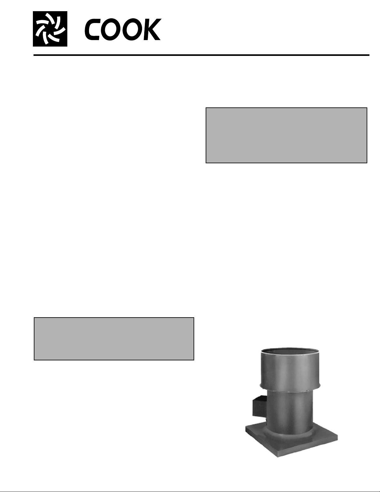
Propeller Upblast
Upblast Propeller Roof Fans
INSTALLATION, OPERATION, AND MAINTENANCE MANUAL
This publication contains the installation, operation
and maintenance procedures for standard units of the
Upblast - Upblast Propeller Roof Fans.
• AUD
• EUB/AUB
• LXU/LEU
• SUB/SUBH
• TUD
• TUB
Carefully read this publication prior to any installa-
tion or maintenance procedure.
Loren Cook catalogs, Propeller Upblast and Propeller
Roof, provide additional information describing the equip-
ment, fan performance, availa ble accessories and specification data.
For additional safety information, refer to AMCA publication 410-96, Safety Practices for Users and Installers of
Industrial and Commercial Fans.
All of the publications listed above can be obtained from
Loren Cook Company by phoning (417) 869-6474, extension 166; by FAX at (417) 832-9431; or by e-mail at
info@lorencook.com.
For information and instructions on special equipment,
contact Loren Cook Company at (417) 869-6474.
Receiving and Inspection
Carefully inspect the fan and accessories for any damage and shortage immediately upon receipt of the fan.
• Turn the propeller by hand to ensure it turns freely and
does not bind.
• Check dampers (if included) for free operation of all
moving parts.
• Record on the Delivery Receipt any visible sign of
damage.
WARNING
This unit has rotating parts. Safety precautions
should be exercised at all times during ins tallat ion,
operation, and maintenance.
ALWAYS disconnect power prior to working on fan.
If your fan has a special protective finish, handle with
extreme care. Even a small chip will break the coating’s
continuity and destroy its ability to protect the metal.
Propellers are carefully balanced to give smooth, vibration-free operation. If the pr opeller is damaged during h andling, it will require rebalancing.
Personal Safety
Disconnect switches are recommended. Place
the disconnect switch near the fan in order that
the power can be swiftly cut off in case of an
emergency, and in order that maintenance personnel are provided complete control of the
power source.
Storage
If the fan is stored for any length of time prior to installation, store it in its original shipping crate and protect it from
dust, debris and the weather.
Outdoor Storage
To maintain good working condition of the f an when it is
stored outdoors or at a construction site, follow the additional instructions below.
• Coat the shaft and bearings with grease or rust preventative compound to help seal out moisture.
• Periodically rotate the propeller and operate the dampers (if supplied) to keep a coating of grease on all internal bearing parts.
• Periodically inspect the fan to prevent damaging conditions.
• Block propeller to prevent natural rotation.
• Cover the unit with some type of weather cover to pre-
vent moisture, corrosion, dirt or dust accumulation.
Handling
Lift propeller roof ventilators by the base or with slings
placed around the fan housing. Never lift by the shaft,
motor, propeller, or coupling.
If you use hooks in the lifting holes of the fan, be careful
not to distort or bend the housing. Large units may have lif ting lugs or holes that should be used instead of a sling.
TUB
Page 2
Installation
1 foot
1/4 inch
Damper Installation
a. Place the damper inside the curb. Ensure the dam pe r
will open freely for the correct direction of the airflow.
b. Secure to curb at the damper shelf by installing at least
two sheet metal screws (#10 x 1/2”) on each side of the
damper, thr ough the tr ay, with the screw head catching
the flange on the damper. This will prevent the dampers
from lifting.
c. Drill a hole in the curb shelf for conduit needed for
motor wiring.
d. Operate the dampers manually to ensure the blades
move freely. Dampers should be released from full
open position to check for proper closing.
Note
An inlet basket guard is recommended. A basket
guard prevents any large debris from being pulled
into the fan and damaging the propeller. The Loren
Cook basket guard is installed on top of the curb
before the fan is installed.
Motor Installation
To prevent damage to the fan during shipping, motors 5
HP and larger, and extremely heavy motors (cast iron or
severe duty) are shipped loose and must be field mounted.
The motor should be mounted so that the motor plate is
between the fan shaft and motor shaft.
a. Remove the motor plate mounting bolts and the motor
plate.
b. Remove the motor mounting bolts from the motor plate.
c. Mount the motor to the motor plate aligning to the
appropriate holes.
d. Place the motor plate on the power assembly and rein-
stall the mounting bolts.
Figure 1
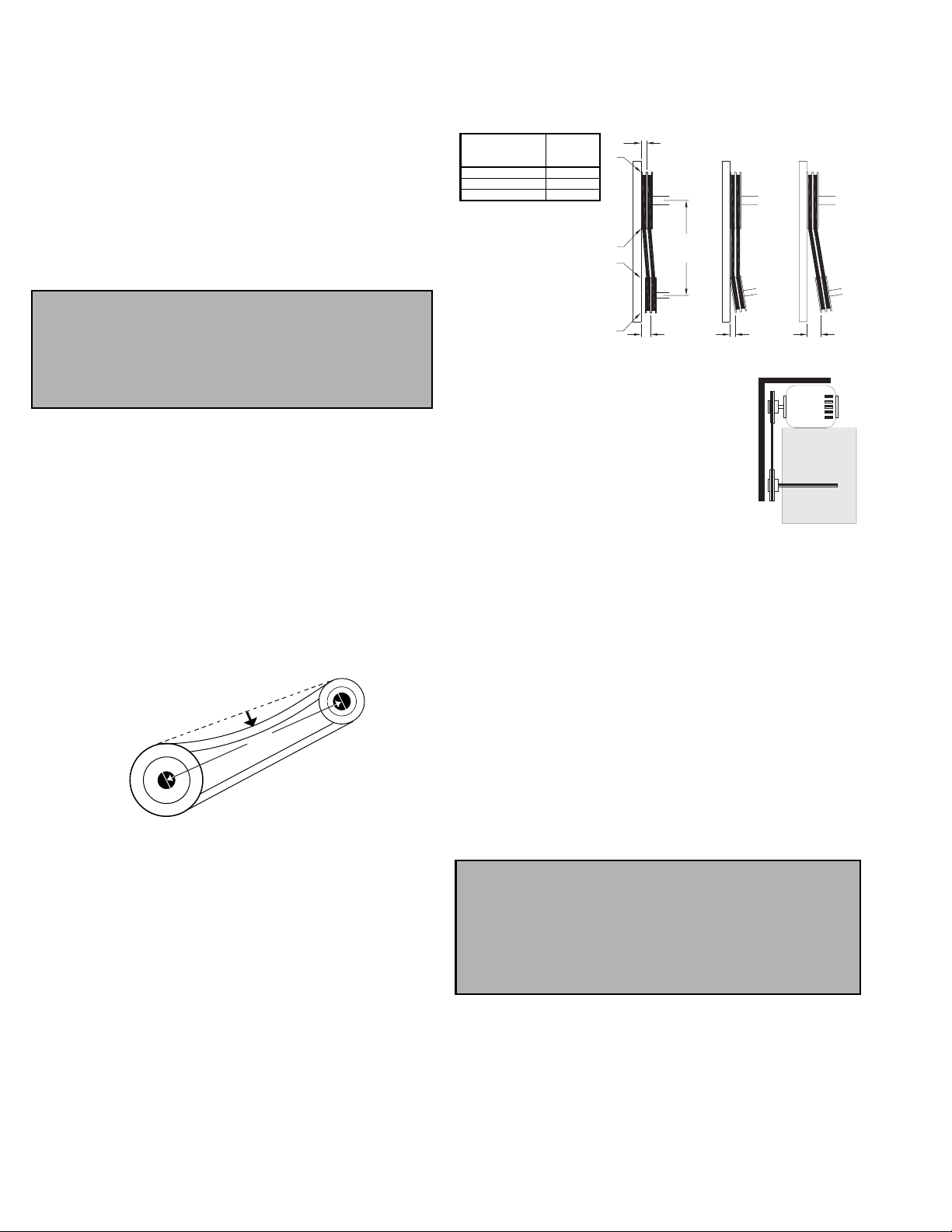
Belt and Pulley Installation
If your fan is a direct drive (model AUD), proceed to Wir-
ing Installation.
Belt tension is determined by the sound of the belts when
the fan is first started. The belts will produce a loud squeal,
which dissipates after the fan is operating at full capacity. If
belt tension is too tight or too loose, lost efficiency and
damage can occur.
Do not change the pulley pitch diameter to change tension. The change will result in a different fan speed.
a. Loosen the motor plate adjustment nuts on motor ba se
and move motor plate in order that the belts can ea sily
slip into the grooves on the pulleys. Never pry, roll, or
force the belts over the rim of the pulley.
b. Adjust the motor plate until proper tension is reached.
For proper tension, a deflection of approximately 1/4”
per foot of center distance should be obtained by firmly
pressing the belt. Refer to Figure 1.
c. Lock the motor plate adjustment nuts in place.
d. Ensure pulleys are properly aligned. Refer to Figure 2.
Tolerance
Center Distance
Up thru 12” 1/16”
12” up through 48 1/8”
Over 48” 1/4”
Figure 2
Maximum
Gap
OFFSET ANGULAR OFFSET/ANGULAR
A
W
B
CENTER
DISTANCE
(CD)
GAP
X
Y
Z
GAP
Pulley Alignment
Pulley alignment is adjusted by loosening
the motor pulley setscrew and by moving
the motor pulley on the motor shaft.
Figure 2 indicates where to measure the
allowable gap for the drive alignment tolerance. All contact points (indicated by
WXYZ) are to have a gap less than the tolerance shown in the table. When the pulleys are not the same width, the allowable
Figure 3
gap must be adjusted by half of the difference in width. Figure 3 illustrates using a carpenter’s square to adjust the
position of the motor pulley until the belt is parallel to the
longer leg of the square.
Wiring Installation
All wiring should be in accordance with local ordinances
and the National Electrical Code, NFPA 70. Ensure the
power supply (voltage, frequency, and current carrying
capacity of wires) is in accordance with the motor nameplate. Refer to the Wiring Diagrams, on page 3.
Lock off all power sources before unit is wired to power
source.
Leave enough slack in the wiring to allow for motor movement when adjusting belt tension. Some fractional motors
have to be removed in order to make the connection with
the terminal box at the end of the motor.
Personal Safety
Disconnect switches are recommended. Place the
disconnect switch near the fan in order that the
power can be swiftly cut off in case of an emergency, and in order that maintenance personnel are
provided complete control of the power source.
2
Page 3
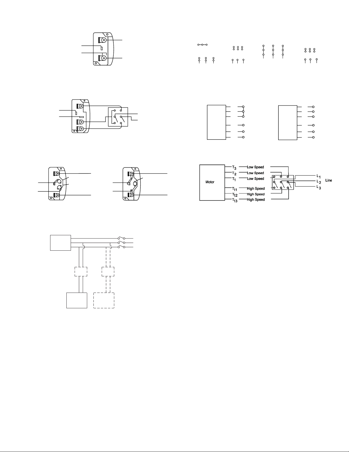
Wiring Diagrams
Single Speed, Single Phase Motor
Ground A
L
T-1
T-4
Ground B
When ground is required, attach to ground A or B with no. 6 thread forming
1
Line
L
2
Wiring Diagrams
3 Phase, 9 Lead Motor
Y-Connection
Low Voltage
208/230 Volts
4
5
6
3
1
9
728
L2L
L
1
3
High Voltage
460 Volts
456
789
3
12
L2L
L
1
To reverse, interchange any 2 line leads.
3 Phase, 9 Lead Motor
Delta-Connection
Low Voltage
208/230 Volts
7
6
1
L
3
1
8
4
2
L
2
screw. To reverse, interchange T-1 and T-4.
2 Speed, 2 Winding, Single Phase Motor 2 Speed, 1 Winding, 3 Phase Motor
Ground A
High Speed
T-1
T-4
L
1
Line
L
2
Low Speed
Ground B
When ground required, attach to ground A or B with No. 6 thread forming
screw. To reverse, interchange T-1 and T-4 leads.
Motor
To reverse, interchange any 2 line leads. Motors require magnetic control.
High Speed
1
Together
2
3
L
4
L
5
6
L
1
2
Line
3
Single Speed, Single Phase, Dual Voltage 2 Speed, 2 Winding, 3 Phase
Ground A
L
Line
L
1
T-5
J-10
2
Ground B
J-10
T-5
Link A
Link B
Low Voltage
Ground B
When ground required, attach to ground A or B with No. 6 thread forming
screw. To reverse, interchange T-5 and J-10 leads.
Ground A
Link A & B
L
Line
L
1
2
To reverse: High Speed-interchange leads T11 and T12.
Low Speed-interchange leads T
line leads.
and T2. Both Speeds-interchange any 2
1
Typical Damper Motor Schematic
9
5
3
L
3
Motor
High Voltage
460 Volts
789
456
12
L1L
L
Low Speed
1
2
3
4
5
6
2
3
3
L
1
L
2
L
3
Open
Line
Fan
Motor
L3
L2
L1
For 3 phase, damper motor voltage should be the same between L1 and
. For single phase application, disregard L3. *Damper motors may be
L
2
available in 115, 230 and 460 volt models. The damper motor nameplate
Transformer**
Transformer**
voltage should be verified prior to connection. ** A transformer may be provided in some installations to correct the damper motor voltage to the
specified voltage.
Damper
Motor*
Second
Damper
Motor
Follow the wiring diagram in the di sc o nn e ct swi tc h
and the wiring diagram provided with the motor. Correctly label the circuit on the main power box and
always identify a closed switch to promote safety (i.e.,
red tape over a closed switch).
Fan Installation
The fan support (roof curb) should provide a level surface
for installation. If the roof is pitched more than 1/2:12, a
sloped curb must be used to correct for the incline. If the
unit is installed on a non-level surface, the damper door
pivot should be positioned perpendicular to the peak of the
roof.
a. Place fan over roof opening.
b. Secure the fan with lag scews, anchor bolts, or other
suitable fasteners.
Final Installation Steps
a. Inspect fasteners and setscrews, particularly fan
mounting and bearing fasteners, and tighten according
to the recommended torque shown in the t able on p age
4, Recommended Torque for Setscrews/Bolts .
b. Inspect for correct voltage with voltmeter.
c. Ensure all accessories are installed.
d. Test the fan to be sure the rotation is the same as indi-
cated by the arrow marked Rotation.
Do not allow the fan to run in the wrong direction.
This will overheat the motor and cause serious damage. For 3-phase motors, if the fan is running in the
wrong direction, check the control switch. It is possible to interchange two leads at this location so that the
fan is operating in the correct direction.
3
Page 4

TUB / SUB / SUBH Additional Installation Steps
Bolt C
Linkage
Bolt A
Figure 4 - SUBH Safety Bolt Removal
Hook B
The damper actuator arms are safety bolted at the factory
to prevent damage or personnel injury during handling and
installation. The bolt must be removed for the damper actuator to operate correctly. Refer to Figure 4.
• Remove Bolt “A” from each of the damper arms.
• Be sure that linkage hook “B” is in contact with bolt “C” to
prevent excessive load on the fusible link.
The damper arms will not operate unless this bolt is
removed. This bolt should be replaced before any maintenance or repair work is started.
Operation
Pre-Start Checks
a. Lock out all the primary and secondary power sources.
b. Inspect fasteners and setscrews, particularly those
used for mounting the unit, and tighten if necessary.
c. Inspect belt tension and pulley alignment. (Remember,
if belt tension is correct, a loud squeal occurs as the fan
increases to full power.)
d. Inspect motor wiring.
e. Ensure the belt touches only the pulleys.
f. Rotate the propeller to ensure it does not rub against the
base.
g. Ensure fan and ductwork are clean and free of debris.
h. Test the fan to ensure the rot ation o f the pro peller is the
same as indicated by the rotation label.
i. Close and secure all access doors.
j. Restore power to unit.
Recommended Torque for Setscrews/Bolts (IN/LB.)
Setscrews
Size
No.10 3/32” 28 33 3/8”-16 240
1/4” 1/8” 66 80 1/2”-13 600
5/16” 5/32” 126 156 5/8”-11 1200
3/8” 3/16” 228 275 3/4”-10 2100
7/16” 7/32” 348 384 7/8”- 9 2040
1/2” 1/4” 504 600 1”- 8 3000
5/8” 5/16” 1104 1200 1-1/8” - 7 4200
3/4” 3/8” 1440 1800 1-1/4” - 7 6000
Key Hex
Across
Flats
Recommended
Torque
Min. Max. Size
Start Up
Turn the fan on. In variable speed units, set the fan to its
lowest speed. Inspect for the following:
• Direction of rotation.
• Excessive vibration.
• Unusual noise.
• Bearing noise.
• Improper belt alignment or tension (listen for a continuous squealing noise).
Hold Down Bolts
Wrench
Torque
• Improper motor amperage or voltage.
If a problem is discovered, immediately shut off the
fan. Lock out all electrical power and check for the
cause of the trouble. Refer to Troubleshooting, page 6.
Inspection
Inspection of the fan should be conducted at the first 30
minute, 8 hour and 24 hour intervals of satisfactory opera-
tion. During the inspections, stop the fan and inspect as per
the chart below.
30 Minute Interval
Inspect bolts, setscrews, and motor mounting bolts.
Adjust and tighten as necessary.
8 Hour Interval
Inspect belt alignment and tension. Adjust and tighten as
necessary.
24 Hour Interval
Inspect belt tension. Adjust and tighten as necessary.
Conditions Chart
RPM Temperature
100 Up to 120°F Clean 6 to 12 months
500 Up to 150°F Clean 2 to 6 months
1000 Up to 210°F Clean 2 weeks to 2 months
1500 Over 210°F Clean Weekly
Any
Speed
Any
Speed
Any
Speed
Any
Speed
Up to 150°F Dirty 1 week to 1 month
Over 150°F Dirty Daily to 2 weeks
Any Temperature Very Dirty Daily to 2 weeks
Any Temperature
Fan
Status
Extreme
Conditions
Greasing
Interval
Daily to 2 weeks
Maintenance
Establish a schedule for inspecting all parts of the fan.
The frequency of inspection depends on the operating conditions and location of the fan.
Inspect fans exhausting corrosive or contaminat ed air
within the first month of operation. Fans exhausting contaminated air (airborne abrasives) should be inspected
every three months. Clean the propeller and air inlets if
material build-up is excessive. Excessive build-up can
cause imbalance and failure of the propeller.
Regular inspections are recommended for fans exhausting non-contaminated air.
It is recommended the following inspections be conducted twice per year.
• Inspect bolts and setscrews for tightness. Tighten as
necessary.
• Inspect belt wear and alignment. Replace worn belts
with new belts and adjust alignment as needed. See
Belt and Pulley Installation, page 2.
• Bearings should be inspected as recommended in the
Conditions Chart.
• Inspect for cleanliness. Clean exterior surfaces only.
Removing dust and grease on motor housing assures
proper motor cooling.
Lubricants
Loren Cook Company uses petroleum lubricant in a lith-
ium base conforming to NLGI grade 2 consistency. Other
4
Page 5

grades of grease should not be used unless the bearings
and lines have been flushed clean. If another grade of
grease is used, it should be lithium-based.
A NLGI grade 2 grease is a light viscosity, low-torque,
rust-inhibiting lubricant that is water resistant. Its temperature range is from -30°F to +200°F and capable of intermittent highs of +250°F.
Motor Bearings
Motor bearings are pre-lubricated and sealed. Under normal conditions they will not require further maintenance for
a period of ten years. However, it is advisable to have your
maintenance department remove and disassemble the
motor, and lubricate the bearings after three years of operation in excessive heat and or in a contaminated air stream
consisting of airborne abrasives.
Fan Bearings
Fan bearings are lubricated through a grease connector
and should be lubricated by the schedule, Conditions
Chart, on page 4.
For best results, lubricate the bearing while the fan is
rotating. Slowly pump grease into the bearing until a slight
bead forms around the bearing seals. Excessive grease
can burst seals thus reduce bearing life.
In the event the bearing cannot be seen, use no more
than three injections with a hand-operated grease gun.
Motor Services
Should the motor prove defective within a one-year
period, contact your local Loren Cook repre sentative or
your nearest authorized electric motor servic e re pr es en tative.
Changing Shaft Speed
All belt driven propeller roof fans with motors up to and
including 5HP are equipped with variable pitch pulleys. To
change the fan speed, perform the following:
a. Loosen setscrew on driver (motor) pulley and remove
key, if equipped.
b. Turn the pulley rim to open or close the groove facing.
If the pulley has multiple grooves, all must be adjusted
to the same width.
c. After adjustment, inspect for proper belt tension.
Speed Reduction
Open the pulley in order that the belt rides deeper in the
groove (smaller pitch diameter).
Speed Increase
Close the pulley in order that the belt rides higher in the
groove (larger pitch diameter). Ensure that the RPM limits
of the fan and the horsepower limits of the motor are maintained.
Maximum RPM
Maximum RPM
Maximum RPM
TUB, SUB,
TUB, SUB,
TUB, SUB,
SUBH
SUBH
SUBH
Size
Size
Size
20 2633 24 1585 24 1650
20 2633 24 1585 24 1650
20 2633 24 1585 24 1650
24 1993 30 1180 30 1305
24 1993 30 1180 30 1305
24 1993 30 1180 30 1305
30 1605 36 1015 36 1305
30 1605 36 1015 36 1305
30 1605 36 1015 36 1305
36 1314 42 935 42 1200
36 1314 42 935 42 1200
36 1314 42 935 42 1200
42 1106 48 845 48 1150
42 1106 48 845 48 1150
42 1106 48 845 48 1150
48 973 54 900
48 973 54 900
48 973 54 900
54 888 60 870
54 888 60 870
54 888 60 870
60 783 72 688
60 783 72 688
60 783 72 688
72 616
72 616
72 616
Maximum
Maximum
Maximum
RPM
RPM
RPM
AUB
AUB
AUB
Maximum
Maximum
Maximum
RPM
RPM
RPM
EUB
EUB
EUB
Maximum
Maximum
Maximum
RPM
RPM
RPM
Maximum RPM
LXUL
Size
20 1270 20 1460 20 1675
24 1110 24 1400 24 1650
30 930 30 1170 30 1350
36 720 36 860 36 1310
42 600 42 718 42 1210
48 508 48 598 48 1214
54 478 54 522 54 946
60 450 60 476 60 854
Maximum
RPM
LXUM
Maximum
RPM
LEU
Maximum
RPM
Pulley and Belt Replacement
a. Clean the motor and fan shafts.
b. Loosen the motor plate mounting bolts to relieve the
belt tension. Remove the belt.
c. Loosen the pulley setscrews and remove the pulleys
from the shaft.
If excessive force is required to remove the pulleys, a
three-jaw puller can be used. This tool, however,
can easily warp a pulley. If the puller is used,
inspect the trueness of the pulley after it is
removed from the shaft. The pulley will need
replacement if it is more than 0.020 inch out of
true.
d. Clean the bores of the pulleys and place a light coat of
oil on the bores.
e. Remove grease, rust and burrs from the shaft.
f. Place fan pulley on the fan shaft and the motor pulley on
the motor shaft. Damage to the pulleys can occur when
excessive force is used in placing the pulleys on their
respective shafts.
g. After the pulleys have been correctly placed back onto
their shafts, tighten the pulley setscrews.
h. Install the belts on the pulleys. Align and adjust the
belts to the proper tension as described in Belt and Pul-
ley Installation, page 2.
Bearing Replacement
The fan bearings are pillow block ball bearings.
a. Remove the wind band and damper assembly to gain
access to the fan.
b. Loosen the motor plate mounting bolts an d remo ve the
drive belts.
c. Remove the propeller from the shaft.
d. Remove the bearing cover . Remove the four (4) bear-
ing hold-down bolts and then remove the shaf t, bear-
ings, and driven sheave from the unit as an assembly.
e. Measure and record the location of the bearings and
sheave on the shaft. This will aid the reassembly.
f. Remove the anti-corrosion coating from the shaft with a
suitable degreaser and then r emove the pulley fro m the
shaft. An emery cloth or file may be needed to remove
imperfections in the shaft left by the setscrews.
5
Page 6

g. Remove the bearing from the shaft using a bearing
puller.
h. Clean the shaft and bearing bores thoroghly.
i. Place the bearings into position making sure they are
not on a worn section of the shaft. Tapping the inner
ring face with a soft driver may be required. T ighten the
setscrews on the lower bearing.
j. Install the pulley in the correct location on the shaft.
Secure the bearing hold-down bolts, but do not fully
tighten.
k. Align the setscrews on the top bearing with those on
the lower bearing. Tighten one of them.
l. Rotate the shaft to allow the bearing outer rings to find
their center of free movement. If your fan is supplied
with a lube line, attach it to the grease connection.
m. Install the propeller on the shaft and adjust bearing
position to center the propeller in the opening.
n. Tighten hold-down bolts to proper torque. Refer to the
Torque Chart on page 4.
o. Turn the shaft by hand. Resist ance should be the same
as it was before hold-down bolts were fully tightened.
p. Tighten bearing setscrews to specified torque.
r. Reassembly the fan.
After 24 hours of continuous operation, tighten the setscrews to the appropriate torque. This assures the full locking of the inner race to the shaft. Ensure the socket key or
driver is in good condition with no rounded corners. The
key should be fully engaged in the setscrew and held
squarely to prevent the rounding out of the se tscrew socket
when applying maximum torque.
Troubleshooting
Problem and Potential Cause
Low Capacity or Pressure
•Incorrect direction of rotation. Make sure the fan rotates in same direction as the arrows on the motor or belt drive assembly.
•Poor fan inlet conditions. There should be a straight clear duct at the
inlet.
•Improper propeller alignment.
Excessive Vibration and Noise
•Damaged or unbalanced propeller.
•Belts too loose; worn or oily belts.
•Speed too high.
•Incorrect direction of rotation. Make sure the fan rotates in same direction as the arrows on the motor or belt drive assembly.
•Bearings need lubrication or replacement.
•Fan surge.
Overheated Motor
•Motor improperly wired.
•Incorrect direction of rotation. Make sure the fan rotates in same direction as the arrows on the motor or belt drive assembly.
•Cooling air diverted or blocked.
•Improper inlet clearance.
•Incorrect fan RPMs.
•Incorrect voltage.
Overheated Bearings
•Improper bearing lubrication
•Excessive belt tension.
Propeller and Shaft Replacement Precautions
• If the shaft is dropped and bent, it may cause unbalanced operation of the fan.
• When handling the propeller separately from the shaft,
place a support through the hub for lifting, making sure
not to injure the finished bore of the propeller.
• Never allow the propeller to rest its entire weight on the
blades. The propeller and shaft can be lifted by slings
around the shaft on each side of the propeller so the
propeller is supported by its hub.
• If using a chain to lift the propeller, make sure there is
sufficient padding on the shaft and propeller. This prevents the scoring of the shaft or injury to the propeller.
The chain or cable should be spread with timbers, or
braced by some other method to prevent damage to
the propeller side plates.
6
Page 7

1
2
3
4
5
6
7
8
9
10
1
2
3
4
5
6
7
8
9
10
11
12
13
14
15
16
17
18
1
2
3
4
5
6
7
8
9
10
11
12
13
14
15
16
17
18
AUD / TUD Parts List
1
2
3
4
5
6
7
8
9
10
11
12
13
14
15
16
17
18
19
20
EUB/AUB Parts List
EUB Sizes 24 - 72
AUB Sizes 24 - 48
Parts
No.
AUD (Sizes 24 - 48) TUD (Sizes 20 - 60)
Description
1 Damper Stop Damper Stop
2 Rubber Bumper(2) Rubber Bumper(2)
3 Wind Band Wind Band
4 Cast Aluminum Propeller Welded Steel Propeller
5 Power Assembly Power Assembly
6 Motor Plate Motor Plate
7 Lower Drum Assembly Lower Drum Assembly
8 Motor Motor
9 Damper Rubber Extrusion (2) Damper Rubber Extrusion (2)
10 Damper Assembly Damper Assembly
Parts
No.
EUB (Sizes 24 - 72) AUB (Sizes 24 - 48)
Description
1 Damper Backstop Damper Backstop
2 Rubber Bumper (2)
Rubber Bumper (2)
3 Damper Rubber Extrusion (2) Damper Rubber Extrusion (2)
4 Shaft Shaft
5 Weather Cover Rubber Extrusion Weather Cover Rubber Extrusion
6 Motor Plate Motor Plate
7 Weather Cover Weather Cover
8 Motor Motor
9 Driver Sheave Driver Sheave
10 Belt Set Belt Set
11 Split Locking Collar Split Locking Collar
12 Driven Sheave Driven Sheave
13 Bearings (2) Bearings (2)
14 Bearing Cover Bearing Cover
15 Lower Drum Assembly Lower Drum Assembly
16
Extruded Aluminum Cast Aluminum
17 Wind Band Assembly Wind Band Assembly
18 Damper Assembly Damper Assembly
Part
No.
SUB/TUB (Sizes 24 - 72) SUBH (Sizes 24 - 72)
Description
1 Damper Backstop Damper Backstop
2 Rubber Bumper (2) Rubber Bumper (2)
3 Damper Rubber Extrusion Damper Rubber Extrusion
4
SUB/SUBH/TUB Parts List
7
5 Motor Plate Motor Plate
6 Weather Cover Weather Cover
7Motor Motor
8 Driver Sheave Driver Sheave
9 Belt Set Belt Set
10 Split Locking Collar Split Locking Collar
11 Driven Sheave Driven Sheave
12 Bearings (2) Bearings (2)
13 Bearing Cover Bearing Cover
14 Lower Drum Assembly Lower Drum Assembly
15 Shaft Shaft
16 Heat Slinger (optional) Heat Slinger
17 Steel Propeller Steel Propeller
18
19 Wind Band Assembly Wind Band Assembly
20 Damper Assembly Damper Assembly
Weather Cover
Rubber Extrusion
Spring Loaded Damper Spring Loaded Damper
Weather Cover
Rubber Extrusion
Page 8

LXUL/LXUM Parts List
1
18
17
16
15
14
13
19
12
11
3
2
10
LEU Parts List
1
3
2
18
17
16
19
Part
No.
4
1
2
3
4
5
5
6
6
7
8
7
8
9
10
11
9
12
13
14
15
4
16
17
18
19
Size 20-24 Size 30-36 Size 42-54 Size 60
Damper Stop Bracket (2)Damper Stop Bracket (2)Damper Stop Bracket (2)Damper Stop Bracket (2)
Damper Stop Channel Damper Stop Channel Damper Stop Channel Damper Stop Channel
Danper Bumper (2) Danper Bumper (2) Danper Bumper (2) Danper Bumper (2)
Windband Windband Windband Windband
X-Stream Propeller X-Stream Propeller X-Stream Propeller X-Stream Propeller
Base Weldment Base Weldment Base Weldment Base Weldment
Motor Plate Motor Plate Motor Plate Motor Plate
Motor Motor Motor Motor
Drive Sheave Drive Sheave Drive Sheave Drive Sheave
Belt Belt Belt Belt
Driven Sheave Driven Sheave Driven Sheave Driven Sheave
- - Locking Collar Locking Collar
3/4” Bore Bearing (2) 1” Bore Bearing (2) 1-3/16” Bore Bearing (2) 1-7/16” Bore Bearing (2)
Shaft Shaft Shaft Shaft
Rain Gutter Rain Gutter Rain Gutter Rain Gutter
Damper Door (2) Damper Door (2) Damper Door (2) Damper Door (2)
Damper Hinge (4) Damper Hinge (4) Damper Hinge (8) Damper Hinge (8)
Damper Pivot Rod Damper Pivot Rod Damper Pivot Rod Damper Pivot Rod
Damper Pivot Bracket Damper Pivot Bracket Damper Pivot Bracket Damper Pivot Bracket
LXUL/LXUM Description
15
5
6
Part
No.
Size 20-36 Size 42-54 Size 60
LEU Description
1 Damper Stop Bracket (2) Damper Stop Bracket (2) Damper Stop Bracket (2)
14
12
13
11
9
10
7
8
2 Damper Stop Channel Damper Stop Channel Damper Stop Channel
3 Damper Bumper (2) Damper Bumper (2) Damper Bumper (2)
4 Windband Windband Windband
5 Extruded Propeller Extruded Propeller Extruded Propeller
6 Base Weldment Base Weldment Base Weldment
7 Motor Plate Motor Plate Motor Plate
8 Motor Motor Motor
9 Drive Sheave Drive Sheave Drive Sheave
10 Belt Belt Belt
11 Driven Sheave Driven Sheave Driven Sheave
12 - Locking Collar Locking Collar
13 1” Bore Bearing (2) 1-3/16” Bore Bearing (2) 1-7/16” Bore Bearing (2)
14 Shaft Shaft Shaft
15 Rain Gutter Rain Gutter Rain Gutter
16 Damper Door (2) Damper Door (2) Damper Door (2)
17 Damper HInge (4) Damper HInge (8) Damper HInge (8)
18 Damper Pivot Rod Damper Pivot Rod Damper Pivot Rod
19
Damper Pivot
Brackets (2)
Damper Pivot
Brackets (2)
Damper Pivot
Brackets (2)
Limited Warranty
Loren Cook Company warrants that your Loren Cook fan was manufactured free of defects in materials and workmanship, to the extent stated herein. For a period of one (1) year
after date of shipment, we will replace any parts found to be defective without charge, except for shipping costs which will be paid by you. This warranty is granted only to the
original purchaser placing the fan in service. This warranty is void if the fan or any part thereof has been altered or modified from its original design or has been abused, misused,
damaged or is in worn condition or if the fan has been used other than for the uses described in the company manual. This warranty does not cover defects resulting from normal
wear and tear. To make a warranty claim, notify Loren Cook Company, General Offices, 2015 East Dale Street, Springfield, Missouri 65803-4637, explaining in writing, in detail,
your complaint and referring to the specific model and serial numb ers of your fan. Upon receipt by Loren Cook Company of your written complaint, you will be notified, within thirty
(30) days of our receipt of your complaint, in writing, as to the manner in which your claim will be handled. If you are entitled to warranty relief, a warranty adjustment will be completed within sixty (60) business days of the receipt of your written complaint by Loren Cook Company. This warranty gives only the original purchaser placing the fan in service
specifically the right. You may have other legal rights which vary from state to state.
Corporate Offices: 2015 E. Dale Street Springfield, MO 65803 417.869.6474
lorencook.com
8
Propeller Upblast IOM - October 2007
 Loading...