

Page 1
Personal Safety
Disconnect switches are recommended. Place
the disconnect switch near the fan in order that
the power can be swiftly cut off in case of an
emergency, and in order that maintenance personnel are provided complete control of the
power source.
H-Series
WARNING
This unit has rotating parts. Safety precautions
should be exercised at all times dur ing ins tallat ion,
operation, and maintenance.
ALWAYS disconnect power prior to working on fan.
Hooded Propeller Roof Fans
INSTALLATION, OPERATION, AND MAINTENANCE MANUAL
This publication contains the installation, operation
and maintenance procedures for standard units of the
H-Series - Hooded Propeller Roof Fans.
•HEE/HES •HXF
•HEF •HEE-D/HES-D
•HER •HEF-D
•HXE/HXS •HER-D
Carefully read this publication prior to any installa-
tion or maintenance procedure.
Loren Cook catalog, H-Series Belt Drive and H-Series
Direct Drive, provide additional information describing the
equipment, fan performance, available accessories and
specification data.
For additional safety inform ation, refer to AM CA publication 410-96, Safety Practices for Users and Installers of
Industrial and Commercial Fans.
All of the publications listed above can be obtained from
Loren Cook Company by phoning 417/869-64 74, exten sion
166; by FAX at 417/832-9431; or by e-mail at info@lorencook.com.
For information and instructions on special equipment,
contact Loren Cook Company at 417/869-6474.
Receiving and Inspection
Carefully inspect the fan and accessories for any damage and shortage immediately upon receipt of the fan.
• Turn the propeller by hand to ensure it turns freely and
does not bind.
• Check dampers (if included) for free operation of all
moving parts.
• Record on the Delivery Receipt any visible sign of
damage.
Handling
Lift the fan by the base or by the shipping carton. Never
lift by the shaft, motor or housing.
If your fan has a special protective finish, handle with
extreme care. Even a small chip will break the coating’s
continuity and destroy its ability to protect the metal.
Propellers are carefully balanced to give smooth, vibration-free operation. If the propeller is damaged during handling, it will require rebalancing.
dust, debris and the weather.
Outdoor Storage
To maintain good working condition of the fan when it is
stored outdoors or at a construction site, follow the instructions below.
• Coat the shaft and bearings with grease or rust preventative compound to help seal out moisture.
• Periodically rotate the propeller and operate the damp-
ers (if supplied) to keep a coating of grease on all internal bearing parts.
• Periodically inspect the fan to prevent damaging condi-
tions.
• Block propeller to prevent natural rotation.
• Cover the unit with some type of weath er cover to pre-
vent moisture, corrosion, dirt or dust accumulation.
Installation
Damper Installation
If your fan is supplied with dampers, follow the directions
below. If your fan does not include dampers, proceed to
Motor Installation.
a. Place the damper inside the curb. Ensure the damper
will open freely for the correct direction of the airflow.
b. Secure to curb at the damper shelf.
c. Drill a hole in the curb shelf for conduit needed for
motor wiring.
d. Operate the dampers manually to ensure the blades
move freely. Dampers should be released from full
open position to check for proper closing.
Motor Installation
If your fan is a direct drive (model HEE-D, HES-D, HEF-D
or HER-D), proceed to Wiring Installation.
Storage
If the fan is stored for any length of time prior to installa-
tion, store it in its original shipping crate and protec t it from
H-Series
Page 2
Fan
Motor
Damper
Motor*
Second
Damper
Motor
T
ransformer**
T
ransformer**
L3
L2
L1
4
5
6
1
728
3
9
L
1
L2L
3
456
789
12
3
L
1
L2L
3
Low Voltage
208/230 Volts
High Voltage
460 Volts
3 Phase, 9 Lead Motor
Y-Connection
7
1
6
789
456
12
3
Low Voltage
208/230 Volts
High Voltage
460 Volts
8
2
4
9
3
5
L1L
3
L
2
L
1
L
3
L
2
3 Phase, 9 Lead Motor
Delta-Connection
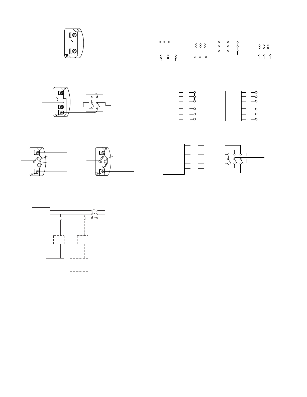
Wiring Diagrams
Wiring Diagrams
Single Speed, Single Phase Motor
Ground A
L
T-1
T-4
Ground B
1
Line
L
2
When ground is required, attach to ground A or B with no. 6 thread forming
screw. To reverse, interchange T-1 and T-4.
To reverse, interchange any 2 line leads.
2 Speed, 2 Winding, Single Phase Motor 2 Speed, 1 Winding, 3 Phase Motor
Ground A
T-1
T-4
Ground B
When ground required, attach to ground A or B with No. 6 thread forming
screw. To reverse, interchange T-1 and T-4 leads.
High Speed
L
1
L
2
Low Speed
Line
1
Together
2
Motor
3
L
1
4
L
5
2
6
Line
L
3
Motor
To reverse, interchange any 2 line leads. Motors require magnetic control.
Single Speed, Single Phase, Dual Voltage 2 Speed, 2 Winding, 3 Phase
Ground A
L
T-5
J-10
Ground B
Link A
Link B
Low Voltage
Line
L
1
T-5
J-10
2
Ground B
When ground required, attach to ground A or B with No. 6 thread forming
screw. To reverse, interchange T-5 and J-10 leads.
Ground A
Link A & B
High Voltage
L
1
Line
L
2
T
Low Speed
3
Low Speed
T
2
Low Speed
T
Motor
T
T
T
1
11
12
13
High Speed
High Speed
High Speed
To reverse: High Speed-interchange leads T11 and T12.
Low Speed-interchange leads T
line leads.
and T2. Both Speeds-interchange any 2
1
Typical Damper Motor Schematic
Low SpeedHigh Speed
L
1
1
L
2
3
4
5
6
2
L
3
Open
Line
L
L
L
1
2
Line
3
To prevent damage to the fan during shipping, motors 5
HP and larger, and extremely heavy motors (cast iron or
severe duty) are shipped loose and must be fie ld mounted.
The motor should be mounted in order that the motor
plate is between the fan shaft and the motor shaft.
a. Remove the motor plate mounting bolts and the moto r
plate.
b. Remove the motor mounting bolts from the motor
plate.
c. Mount the motor to the motor plate aligning to the
appropriate holes.
d. Place the motor plate on the power assembly and rein -
stall the mounting bolts.
Belt and Pulley Installation
Belt tension is determined by the sound of the belts when
the fan is first started. The belts will produce a loud squeal,
For 3 phase, damper motor voltage should be the same between L1 and
. For single phase application, disregard L3. *Damper motors may be
L
2
available in 115, 230 and 460 volt models. The damper motor nameplate
voltage should be verified prior to connection. **A transformer may be provided in some installations to correct the damper motor voltage to the
specified voltage.
which dissipates after the fan is operating at full capacity. If
belt tension is too tight or too loose, lost efficiency and damage can occur.
Do not change the pulley pitch diameter to change ten-
sion. The change will result in a different fan speed.
a. Loosen the motor plate adjustment nuts on motor b ase
and move motor plate in order that the belts can easily
slip into the grooves on the pulleys. Never pry, roll, or
force the belts over the rim of the pulley.
b. Adjust the motor plate until proper tension is reached.
For proper tension, a deflection of approximately 1/4”
per foot of center distance should be obtained by firmly
pressing the belt. Refer to Figure 1.
c. Lock the motor plate adjustment nuts in place.
d. Ensure pulleys are properly aligned. Refer to Figure 2.
2
Page 3
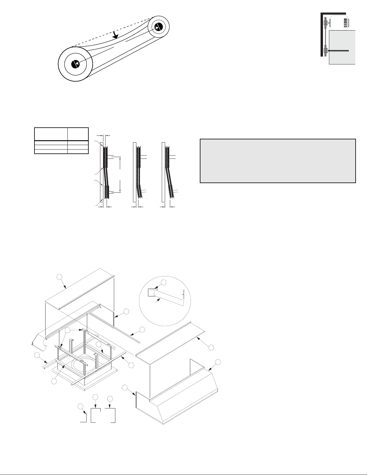
Pulley Alignment
1 foot
1/4 inch
Figure 1
Figure 2
Tolerance
Center Distance
Maximum
Gap
Up thru 12” 1/16”
12” up through 48 1/8”
Over 48” 1/4”
Personal Safety
Disconnect switches are recommended. Place the
disconnect switch near the fan in order that the
power can be swiftly cut off in ca se of an emerge ncy,
and in order that maintenance personnel are provided complete control of the power source.
B
G
C
B
A
E
F
D
F
E
E
Filter
Filter Installation Detail
G
E
C
F
Pulley alignment is adjusted by loosening the motor pulley setscrew and by moving the motor pulley on the motor
shaft.
OFFSET ANGULAR OFFSET/ANGULAR
A
W
ference in width. Figure 3 illustrates using a
carpenter’s square to adjust the position of
the motor pulley until the belt is parallel to
the longer leg of the square.
Wiring Installation
All wiring should be in accordance with
local ordinances and the National Electrical
Code, NFPA 70. Ensure the power supply
Figure 3
(voltage, frequency, and current carrying capacity of wires)
is in accordance with the motor nameplate. Refer to the
Wiring Diagrams, previous page.
Lock off all power sources before unit is wired to
power source.
Leave enough slack in the wiring to allow for motor
movement when adjusting belt tension. Some fractional
motors have to be removed in order to make the connection with the terminal box at the end of the motor.
B
CENTER
DISTANCE
(CD)
GAP
X
Y
Z
Figure 2 indicates where to measure the allowable gap
for the drive alignment tolerance. All contact points (indicated by WXYZ) are to have a gap less than the tolerance
shown in the table. When the pulleys are not the same
width, the allowable gap must be adjusted by half of the dif-
Figure 4
GAP
Follow the wiring diagram in the di sc o nn e ct swi tc h
and the wiring diagram provided with the motor. Correctly label the circuit on the main power box and
always identify a closed switch to promote safety (i.e.,
red tape over a closed switch).
Fan Installation
The fan support (roof curb) should provide a level surface
for installation. If the roof is pitched more than 1/2:12, a
sloped curb must be used to correct the problem.
Place fan over roof opening. Secure the fan with lag
screws, anchor bolts, or other suitable fasteners.
Hood Assembly
Hoods for some non-filtered fans (size 54 and
larger) and some filtered fans (size 48 or larger)
require field assembly . Assembly is accomplished
using 1/2” and 9/16” socket wrenches. Line-up
punches and hand clamps will speed up the
assembly. Figure 4 shows the components used
to assembly the hood.
a. Place the hood halves (A) onto the hood sup-
ports (D). Line up the hood flanges an d bolt the
flanges of the hood ends (G) together. The top
caps (B) must be interlocked for the flanges to
meet correctly.
b. Go under the hood and bolt the hood (angle
flange) to the hood supports (D) at the four
overlapping locations.
c. Install the two perimeter angles (C), that were
shipped loose, inside each end of the hood.
d. If there is a gap between the top cap edges,
loosen the top cap bolts. Install a bolt in each
end of the top cap flange to pull the two top
caps together. Tighten the top cap bolts.
3
Page 4

Filtered Fans
Filter
Schedule
Type 2
Type 2
Type 2
Type 2
Type 2
Type 2
Type 2
Type 2
Type 2
Type 2
Type 1
Type 1
Type 1
Type 1
Type 1
Type 1
Recommended Torque for Setscrews/Bolts (IN/LB.)
Setscrews
Hold Down Bolts
Size
Key Hex
Across
Flats
Recommended Torque
Inch-lbs.
Min. Max. Size
Wrench Torque
(inch-lbs)
No.10 3/32” 28 33 3/8”-16 240
1/4” 1/8” 66 80 1/2”-13 600
5/16” 5/32” 126 156 5/8”-11 1200
3/8” 3/16” 228 275 3/4”-10 2100
7/16” 7/32” 348 384 7/8”-9 2040
1/2” 1/4” 504 600 1”-8 3000
5/8” 5/16” 1104 1200 1-1/8”-7 4200
3/4” 3/8” 1440 1800 1-1/4”-7 6000
WARNING
Disconnect power before checking and cleaning
filters. Inadvertent operation of the fan cou ld pull
objects from the roof into the propeller.
a. Place the two long filter retainers (E) --four on size 60--
and the two short filter retainers (F) on top of the base
and bolt the pieces together.
b. Bolt the long filter retainers (E) to the perimeter angles
(C) that are at the ends of each hood.
c. Install filters according to the filter schedule. Refer to
Filter Installation Detail, below . In sert edge of filters into
the filter retainer (E), swing filter into position and flip
the filter holding clip into position.
Unit Type 1 Type 2
Size Length x Width No. Req’d Length x Width No. Req’d
20 14 x 14” 4 14 x 18-7/8” 6
24 18-1/4” x 30-1/8” 2 18-1/4” x 33-1/4” 4
30 20-7/16” x 18-1/16” 4 20-7/16” x 25-13/16” 6
36 22-1/4” x 21-1/16” 4 22-1/4” x 29-5/32 6
42 24-1/16” x 29-1/2” 4 26-7/8” x 19-1/4” 8
48 27” x 27” 4 27” x 27 8
54 29-1/8” x 20” 6 29-1/8” x 23-5/8” 10
60 37-11/16” x 21-7/8 6 26” x 28-5/16” 10
Final Installation Steps
a. Inspect fasteners and setscrews, particularly fan
mounting and bearing fasteners, and tighten ac cording
to the recommended torque shown in the table, Rec-
ommended Torque for Setscrews/Bolts.
b. Inspect for correct voltage with voltmeter.
c. Ensure all accessories are installed.
d. Test the fan to be sure the rotation is the same as indi-
cated by the arrow marked Rotation.
Do not allow the fan to run in the wrong direction.
This will overheat the motor and cause serious damage. For 3-phase motors, if the fan is running in the
wrong direction, check the control switch. It is possible
to interchange two leads at this locat ion so tha t the fan
is operating in the correct direction.
Operation
Pre-Start Checks
a. Lock out all the primary and secondary power sources.
b. Inspect fasteners and setscrews, particularly those
used for mounting the fan, and tighten if necessary.
c. Inspect belt tension and pulley alignment. (Remember,
if belt tension is correct, a loud squeal occurs as the fan
increases to full power.)
d. Inspect motor wiring.
e. Ensure the belt touches only the pulleys.
f. Rotate the propeller to ensure it does not rub again st
the venturi.
g. Ensure fan and ductwork are clean and free of debris.
h. Test the fan to ensure the rotation of the propeller is
the same as indicated by the rotation label.
i. Close and secure all access doors.
j. Restore power to unit.
Start Up
Turn the fan on. In variable speed fans, set the fan to its
lowest speed. Inspect for the following:
• Direction of rotation.
• Excessive vibration.
• Unusual noise.
• Bearing noise.
• Improper belt alignment or tension (listen for a continuous squealing noise).
• Improper motor amperage or voltage.
If a problem is discovered, immediately shut off the
fan. Lock out all electrical power and check for the
cause of the trouble. Refer to Troubleshooting, page 6.
Inspection
Inspection of the fan should be conducted at the first 30
minute, 8 hour and 24 hour intervals of satisfactory oper a-
tion. During the inspections, stop the fan and i nspect as per
the chart below.
30 Minute Interval
Inspect bolts, setscrews, and motor mounting bolts.
Adjust and tighten as necessary.
8 Hour Interval
Inspect belt alignment and tension. Adjust and tighten as
necessary.
24 Hour Interval
Inspect belt tension. Adjust and tighten as necessary.
Filters
Filter inspection and cleaning intervals can vary from
once a week to twice per year depending on contaminant
present and acceptable pressure drops across the filter.
Under most conditions filters may be cleaned with hot
water and a mild soap solution (such as dish washing liquid) or steam. Some caustic cleaners will damage the filter.
If in doubt, please consult the factory for a compatibility list.
4
Page 5

Relubrication Intervals
Service
Conditions
NEMA Frame Size
Up to and
including 184T
213T-365T 404T and larger
1800 RPM
and less
Over 1800
RPM
1800 RPM
and less
Over 1800
RPM
1800 RPM
and less
Over 1800
RPM
Standard 3 yrs. 6 months 2 yrs. 6 months 1 yr. 3 months
Severe 1 yr. 3 months 1 yr. 3 months 6 months 1 months
High pressure spray washers should be limited to
2,000psi operating pressure. Every attempt should be
made to remove the contaminants from the filter in a “backwash” flow (note airflow arrow on the filter frame). Once the
filter is dry, it may be returned to the appropriate filter racks
in the same orientation (airflow direction) as they were
removed.
Maintenance
Establish a schedule for inspecting all parts of the fan.
The frequency of inspection depends on the operating conditions and location of the fan.
Inspect fans exhausting corrosive or contaminated air
within the first month of operation. Fans exhausting contaminated air (airborne abrasives) should be inspected
every three months. Clean the propeller and air inlet s if
material build-up is excessive. Excessive build-up can
cause imbalance and failure of the propeller.
Regular inspections are recommended for fans exhausting non-contaminated air.
It is recommended the following inspections be conducted twice per year.
• Inspect bolts and setscrews for tightness. Tighten as
necessary.
• Inspect belt wear and alignment. Replace worn belts
with new belts and adjust alignment as needed. See
Belt and Pulley Installation, page 2.
• Bearings should be inspected as recomme nde d in th e
Conditions Chart.
• Inspect for cleanliness. Clean exterior surfaces only.
Removing dust and grease on motor housing assures
proper motor cooling.
Fan Bearings
The fan bearings are provided prelubricated. Any specialized lubrication instructions on fan labels supercedes
information provided herein. Bearing grease is a petroleum
lubricant in a lithium base conforming to a NLGI #2 consistency. If user desires to utilize another type of lubricant,
they take responsibility for flushing bearings and lines, and
maintaining a lubricant that is compatible with the installation.
A NLGI #2 grease is a light viscosity, low-torque, rustinhibiting lubricant that is water resistant. Its temperature
range is from -30°F to 200°F and capable of intermittent
highs of 250°F.
Bearings should be relubricated in accordance with the
condition chart below.
For best results, lubricate the bearing while the fan is in
operation. Pump grease in slowly until a slight bead forms
around the bearing seals. Excessive grease can damage
seal and reduce life through excess contamination and/or
loss of lubricant.
In the event that the bearing cannot be seen, use no
more than three injections with a hand operated grease
gun.
Motor Bearings
Motors are provided with prelubricated bearings. Any
lubrication instructions shown on the motor nameplate
supersede instructions below.
Direct Drive 1050/1075,1200,1300 &1500 rpm units use
a prelubricated sleeve bearing that has a oil saturated wicking
material surrounding it. The initial factory lubrication is ade-
Conditions Chart
Conditions Chart
RPM Temp °F Greasing Interval
RPM Temp °F Greasing Interval
-30 to 120 6 months
Up to 1000
Up to 1000
1000 to 3000
1000 to 3000
Over 3000
Over 3000
Any Speed < -30 Consult Factory
Any Speed < -30 Consult Factory
Any Speed > 200 1 week
Any Speed > 200 1 week
For moist or otherwise contaminated installations; divide the interval by a
For moist or otherwise contaminated installations; divide the interval by a
factor of 3. For vertical shaft installations divide the interval by a factor of 2.
factor of 3. For vertical shaft installations divide the interval by a factor of 2.
-30 to 120 6 months
120 to 200 2 months
120 to 200 2 months
-30 to 120 3 months
-30 to 120 3 months
120 to 200 1 month
120 to 200 1 month
-30 to 120 1 month
-30 to 120 1 month
120 to 200 2 weeks
120 to 200 2 weeks
quate for up to 10 years of operation under normal conditions.
However, it is advisable to add lubricant after 3 years. Use
only LIGHT grade mineral oil or SAE 10W oil up to 30 drops. If
the unit has been stored for a year or more it is advisable to
lubricate as directed above. For VCR direct drive units and
other units in severe conditions, lubrication intervals should be
reduced to half.
Motors without sleeve bearings (as described above) will
have grease lubricated ball or roller bearings. Motor bearings
without provisions for relubrication will operate up to 10 years
under normal conditions with no maintenance. In severe applications, high temperatures or excessive contaminates, it is
advisable to have the maintenance department disassemble
and lubricate the bearings after 3 years of operation to prevent interruption of service.
For motors with provisions for relubrication, follow intervals
of the table below.
Motors are provided with a polyurea mineral oil NGLI #2
grease. All additions to the motor bearings are to be with a
compatable grease such as Exxon Mobil Polyrex EM and
Chevron SRI.
The above intervals should be reduced to half for vertical
shaft installations.
Motor Services
Should the motor prove defective within a one- ye ar per io d,
contact your local Loren Cook representative or your nearest
authorized electric motor service representative.
5
Page 6

Changing Shaft Speed
All belt driven H-Series fans with motors up to and including 5HP are equipped with variable pitch pulleys. To
change the fan speed, perform the following:
a. Loosen setscrew on driver (motor) pulley and remove
key, if equipped.
b. Turn the pulley rim to open or close the groove facing.
If the pulley has multiple grooves, all must be adjusted
to the same width.
c. After adjustment, inspect for proper belt tension.
Maximum RPM
HXEL, HXSL, HXFL
Size
20 1276 20 1462
24 1126 24 1400
30 932 30 1184
36 720 36 864
42 610 42 718
48 516 48 598
54 478 54 522
60 450 60 539
Maximum
RPM
HXEM, HXSM, HXFM
Size
Maximum
RPM
Maximum RPM
HEE
Maximum
Size
RPM
24 1675 24 1630 24 1635 24 1635
30 1295 30 1330 30 1330 30 1325
36 1125 36 1165 36 1160 36 1145
42 880 42 885 42 880 42 920
48 822 48 830 48 816 48 818
54 776 54 742 54 735 54 748
60 636 60 642 60 634 60 642
Speed Reduction
Open the pulley in order that the belt rides deeper in the
groove (smaller pitch diameter).
Speed Increase
Close the pulley in order that the belt rides higher in the
groove (larger pitch diameter). Ensure that the RPM limits
of the fan and the horsepower limits of the motor are maintained.
HES
Size
Maximum
RPM
HEF
Size
Maximum
RPM
HER
Size
Maximum
RPM
Pulley and Belt Replacement
a. Clean the motor and fan shafts.
b. Loosen the motor plate mounting bolts to relieve the
belt tension. Remove the belt.
c. Loosen the pulley setscrews and remove the pulleys
from the shaft.
If excessive force is required to remove the pulleys, a
three-jaw puller can be used. This tool, however, can
easily warp a pulley. If the puller is used, inspect the
trueness of the pulley after it is removed from the shaf t.
The pulley will need replacement if it is more than
0.020 inch out of true.
Pulley and Belt Replacement continued
d. Clean the bores of the pulleys and place a light coat of
oil on the bores.
e. Remove grease, rust and burrs from the shaft.
f. Place fan pulley on the fan shaft and the motor pulley
on the motor shaft. Damage to the pulleys can occur
when excessive force is used in placing the pulleys on
their respective shafts.
g. After the pulleys have been correctly placed back onto
their shafts, tighten the pulley setscrews.
h. Install the belts on the pulleys. Align and adjust the
belts to the proper tension as described in Belt and Pul-
ley Installation, page 2.
Bearing Replacement
The fan bearings are pillow block ball bearings.
a. Remove the top cap or hood as necessary to gain
access to the fan.
b. Loosen the motor plate mounting bolts and remo ve the
drive belts.
c. Remove the propeller from the shaft.
d. Remove the four (4) bearing hold-down bolts and then
remove the shaft, bearings, and driven sheave from the
unit as an assembly.
e. Measure and record the location of the bearings and
sheave on the shaft. This will aid the reassembly.
f. Remove the anti-corrosion coating from the shaft with
a suitable degreaser and then remove the pulley from
the shaft.
g. Remove the bearing from the shaft using a bearing
puller.
h. Install the pulley in the correct location on the shaft
Secure the bearing hold-down bolts, but do not fully
tighten.
i. Align the setscrews on the bearings and tighten one
setscrew on each bearing.
j. Rotate the shaft to allow the bearing outer rings to find
their center of free movement.
k. Install the propeller on the shaft and adjust the bearing
position to center the propeller in the opening.
l. Tighten the hold-down bolts to the proper torque. Refer
to Torque Chart, page 4 .
m. Turn the shaft by ha nd. Resistance should be the same
as it was before the hold-down bolts were fully tight-
ened.
n. Tighten the bearing setscrews to the specified torque.
o. Install the pulley and adjust the belt tension.
p. Reassemble the fan.
After 24 hours of continuous operation, tighten the setscrews to the appropriate torque. This assures the full locking of the inner race to the shaft. Ensure the socket key or
driver is in good condition with no rounded corners. The
key should be fully engaged in the setscrew and held
squarely to prevent the rounding out of the set screw socket
when applying maximum torque.
Propeller and Shaft Replacement Precautions
• If the shaft is dropped and bent, it may cause unbalanced operation of the fan.
• When handling the propeller separately from the shaft,
place a support through the hub for lifting, making sure
not to injure the finished bore of the propeller.
• Never allow the propeller to rest its entire weight on the
blades. The propeller and shaft can be lifted by slings
around the shaft on each side of the propeller so the
propeller is supported by its hub.
• If using a chain to lift the propeller, make sure there is
sufficient padding on the shaft and propeller. This prevents the scoring of the shaft or injury to the propeller.
The chain or cable should be spread with timbers, or
braced by some other method to prevent damage to
the propeller side plates.
6
Page 7

17
16
15
14
13
12
11
10
9
8
7
6
5
4
3
2
1
7
6
5
4
3
2
1
9
10
11
12
8
Troubleshooting
Problem and Potential Cause
Low Capacity or Pressure
•Incorrect direction of rotation. Make sure the fan rotates in same direction
as the arrows on the motor or belt drive assembly.
•Poor fan inlet conditions. There should be a straight clear duct at the inlet.
•Improper propeller alignment.
Excessive Vibration and Noise
•Damaged or unbalanced propeller.
•Belts too loose; worn or oily belts.
•Speed too high.
•Incorrect direction of rotation. Make sure the fan rotates in same direction
as the arrows on the motor or belt drive assembly.
•Bearings need lubrication or replacement.
•Fan surge.
Overheated Motor
•Motor improperly wired.
•Incorrect direction of rotation. Make sure the fan rotates in same direction
as the arrows on the motor or belt drive assembly.
•Cooling air diverted or blocked.
•Improper inlet clearance.
•Incorrect fan RPMs.
•Incorrect voltage.
Overheated Bearings
•Improper bearing lubrication
•Excessive belt tension.
HEE/HES/HER Parts List
4
7
5
3
1
2
17
16
6
15
14
9
8
10
HXEL/HXEM/HXSL/HXSM Parts List
11
12
Part
No.
1 — — Hood Support Angle(2)
2 Motor Motor Motor
13
3
4 Motor Plate Motor Plate Motor Plate
5 Belts Belts Belts
6 — — Center Post (2)
7 Fan Sheave Fan Sheave Fan Sheave
8 Shaft Shaft Shaft
9 Topcap Topcap Topcap
10 Corner Post (4) Corner Post (4) Corner Post (4)
11 Hood End Hood End Hood End
12 Hood Side Hood Side Hood Side
13 Perimeter Angle (4) Perimeter Angle (4) Perimeter Angle (4)
14 Bearings Bearings Bearings
15 HXEM/HXSM/HXEL/HXSL - X-Stream Propeller:
16 Base Assembly: Power Assembly
17 Supply Venturi Supply Venturi Supply Venturi
HEF, HES, HEE, HER, HXEL, HXEM, HXSL, HXSM
20-30 36-48 54-72
Motor Sheave Motor Sheave Motor Sheave
HEE/HES/HER - Extruded Propeller
HEE-D/HES-D/HER-D Parts List
Part
No.
1 — — Hood Support Angle (2)
2 Motor Motor Motor
3 Motor Plate
4—
5 Topcap
6 Corner Post (4)
7 Hood End
8 Hood Side
9 Perimeter Angle (4)
10 Extruded Propeller
11 Base Assembly/
12 Supply Venturi
7
20-30 36-48 54-60
Power Assembly
HEE-D/HES-D/HER-D
Motor Plate
—
Topcap
Corner Post (4)
Hood End
Hood Side
Perimeter Angle (4)
Extruded Propeller
Base Assembly/
Power Assembly
Supply Venturi
Motor Plate
Center Post (2)
Topcap
Corner Post (4)
Hood End
Hood Side
Perimeter Angle (4)
Extruded Propeller
Base Assembly/
Power Assembly
Supply Venturi
Page 8

7
6
5
4
3
2
1
10
11
9
8
12
13
15
16 14
21
20
19
18
17
16
15
14
13
12
11
10
9
8
7
6
5
4
3
2
1
1
2
3
4
5
6
7
8
9
10
11
12
13
14
15
16
17
18
19
20
21
HEF Parts List
HXFL/HXFM Parts List
Part
No.
24-30 36-42 48 54 60
1 — Hood
HEF, HXFL & HXFM
Hood Support Angle
Support Angle
2 Motor Motor Motor
3 Motor Sheave Motor Sheave Motor Sheave
4 Motor Plate Motor Plate Motor Plate
5 Belt Belt Belt
6 — — — Center Post
7 Fan Sheave Fan Sheave Fan Sheave
8 Shaft Shaft Shaft
9 Topcap Topcap Topcap
10 — Corner Post Corner Post
11 Hood End Hood End Hood End
12 Hood Side Hood Side Hood Side
13 Perimeter Angle (4) Perimeter Angle (4) Perimeter Angle (4)
14 Filter Rack (2) Filter Rack (2) Filter Rack (2)
15 Power Assembly Power Assembly Power Assembly
16 Bearings Bearings Bearings
17 HEF - Extruded Propeller:
HXFL/HXFM - X-Stream Propeller
18 Base Assembly Base Assembly Base Assembly
19 Supply Venturi Supply Venturi Supply Venturi
20 Filter Crossmember Filter Crossmember Filter Crossmember
21 Filter* Filter* Filter*
* See Filter Schedule on page 4
HEF-D Parts List
Part
No.
20-30 36-42 48 54 60
HEF-D
1 — Hood
Hood Support Angle
Support Angle
2 Motor Motor Motor
3 Motor Plate Motor Plate Motor Plate
4— — —Center Post
5 Topcap Topcap Topcap
6 — Corner Post (4) Corner Post (4)
7 Hood End Hood End Hood End
8 Hood Side Hood Side Hood Side
9 Perimeter Angle (4) Perimeter Angle (4) Perimeter Angle (4)
10 Filter Rack (2) Filter Rack (2) Filter Rack (2)
11 Power Assembly Power Assembly Power Assembly
12 Extruded
Propeller
Extruded
Propeller
Extruded
Propeller
13 Base Assembly Base Assembly Base Assembly
14 Supply Venturi Supply Venturi Supply Venturi
15 Filter Crossmember Filter Crossmember Filter Crossmember
16 Filter* Filter* Filter*
* See Filter Schedule on page 4
Limited Warranty
Loren Cook Company warrants that your Loren Cook fan was manufactured free of defects in mat eri als and workmanship, to th e exte nt stated he rein. For a p eriod of one (1 )
year after date of shipment, we will replace any parts found to be defective without charge, except for shipping costs which will be paid by you. This warranty is granted only
to the original purchaser placing the fan in service. This warranty is void if the fan or any part thereof has been altered or modified from its original design or has been
abused, misused, damaged or is in worn condition or if the fan has been use d other than for the uses described in the company manual. This warranty does not cover defe cts
resulting from normal wear and tear. To make a warranty claim, notify Loren Cook Company, General Offices, 2015 East Dale Street, Springfield, Missouri 65803-4637,
explaining in writing, in detail, your complaint and referring to the specific model and serial numbers of your fan. Upon receipt by Loren Cook Company of your written complaint, you will be notified, within thirty (30) days of our receipt of your compla int, in writing , as to t he manner in which your claim will be han dled. If you are ent itled to wa rranty
relief, a warranty adjustment will be completed within sixty (60) business days of the receipt of your written complaint by Loren Cook Company. This warranty gives only the
original purchaser placing the fan in service specifically the right. You may have other legal rights which va ry from state to state.
Corporate Offices: 2015 E. Dale Street Springfield, MO 65803 417.869.6474
lorencook.com
8
H-Series IOM - November 2007
 Loading...