

Page 1
INSTALLATION, OPERATION, AND MAINTENANCE MANUAL
WARNING!
To reduce the risk of fire, electric shock, or injury to persons, observe
the following:
• Suitable for use with solid-state speed controls.
• Use this unit only in the manner intended by the manufacturer. If you
have questions, contact the manufacturer.
• Before servicing or cleaning unit, switch power off at service panel and
lock service disconnecting means to prevent power from being switch
on accidentally. When the service disconnecting means cannot be
locked, securely fasten a prominent warning device, such as a tag, to
the service panel.
• Installation work and electrical wiring must be done by qualified
person(s) in accordance with all applicable codes and standards,
including fire-rated construction.
• When cutting or drilling into wall or ceiling, do not damage electrical
wiring or other hidden utilities.
• When installed in a GFCI protected branch circuit unit is acceptable for
use over a bathtub or shower.
• Never place a switch where it can be reached from a tub or shower.
• Ducted fans must always be vented to the outdoors.
CAUTION!
• For general ventilating use only. Do not use to exhaust hazardous or
explosive materials and vapors.
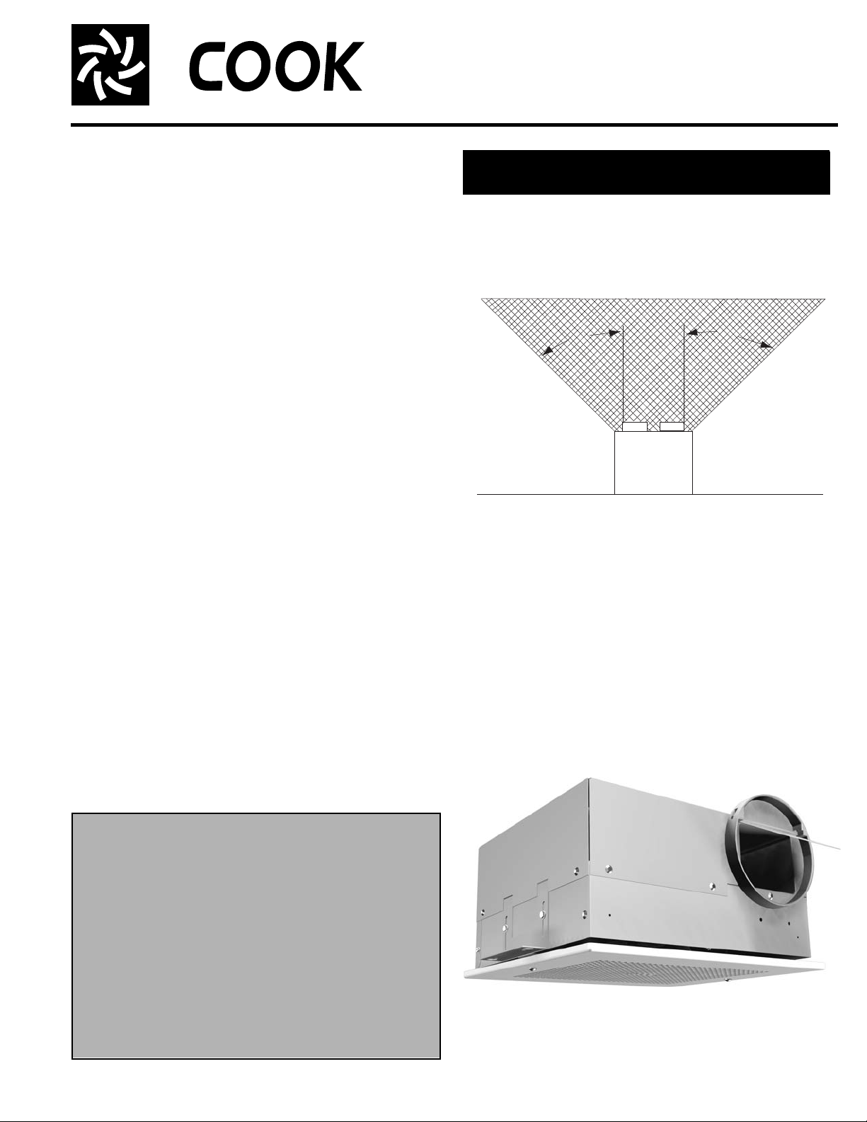
45
Cooking
Equipment
Floor
45
Do not install above or inside shaded area
READ AND SAVE THESE INSTRUCTIONS!
This publication contains the installation, operation
and maintenance procedures for standard units of the
Gemini - Ceiling and Cabinet Fans. Carefully read this
publication prior to installation.
Loren Cook catalog, Gemini, provides additional information describing the equipment, fan performance, available
accessories and specification data.
For additional safety information, refer to AMCA publication 410-96, Safety Practices for Users and Installers of
Industrial and Commercial Fans.
All of the publications listed above can be obtained from
Loren Cook Company by phoning (417) 869-6474, extension 166; by FAX at (417) 832-9431; or by e-mail at
info@lorencook.com.
For information and instructions on special equipment,
contact Loren Cook Company at (417) 86 9-6474.
Gemini 100 Series
UL 507
Ceiling and Cabinet Fans
Installation
Motor Installation
All Gemini units are shipped with motors mounted at the
factory.
Receiving and Inspection
Carefully inspect the fan and accessories for any damage and shortage immediately upon receipt of the fan.
• Turn the wheel by hand to ensure it turns freely and
does not bind.
• Inspect dampers (if included) for free operation of all
moving parts.
• Remove mounting brackets from packing insert.
• Install mounting brackets as shown in Figure 6.
• Remove shipping tape.
• Record on the Delivery Receipt any visible sign of
damage.
Handling
Lift fan by the outside housing (box) or by the blower
mounting brace. Never lift by the shaft or motor.
Storage
If the fan is stored for any length of time prior to installation, store it in its original shipping crate and protect it from
dust, debris and the weather.
Fan Installation
a. Fasten duct work to the outside of the duct collar
(damper frame) using sheet metal screws. Make sur e
sheet metal screws are placed where they do not interfere with damper operation. Do not mount near cooking
equipment (see above figure).
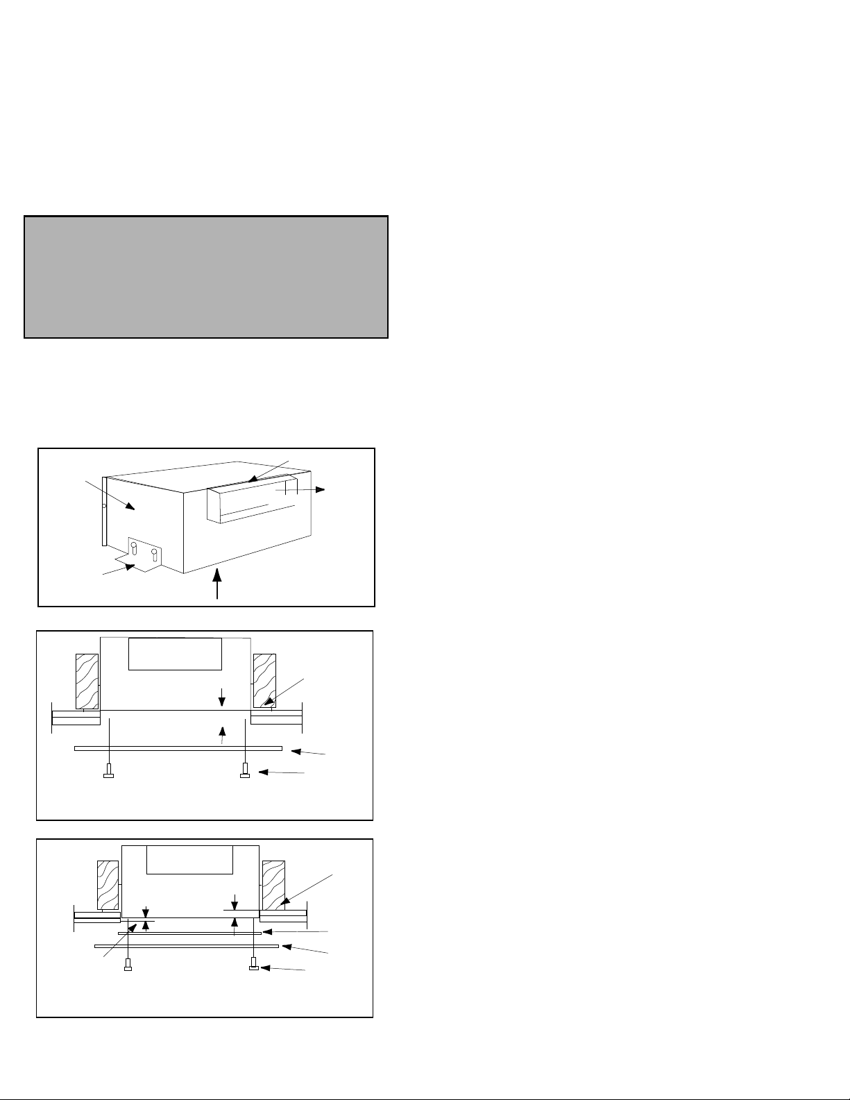
b. Fasten the housing to the bottom of the joists through
the holes provided in the mounting bracket. Refer to figure 1.
c. Adjust housing, using the adjust mounting bracket provided, to allow for the thickness of finished ceiling and grille.
Refer to figure 2. If a unit is furnished with filters allow 3/8”
for filters. Refer to figure 3.
Gemini 100
Page 2
Ceiling Radiation Damper Installation (See Gemini/CRD
Personal Safety
Disconnect switches are recommended. Place the
disconnect switch near the fan in order that the
power can be swiftly cut off in case of an emergency, and in order that maintenance personnel are
provided complete control of the power source.
Side
Panel
Mounting
Brackets
Intake
Side Discharge
Exhaust
Duct Collar
Note: Allow for ceiling thickness. Allow 5/8” for premium aluminum grille
Suggested Installation: Unit without filter.
Note: Allow for ceiling thickness
Suggested Installation: Unit with filter
Figure 1
Figure 2
Figure 3
SEE NOTE
Screw
Grille
Filter
Mounting
Bracket
Allow 3/8"
for filter
SEE NOTE
Mounting
Bracket
Grille
Screw
Installation Supplement)
Wiring Installation
All wiring should be in accordance with local ordinances
and the National Electrical Code, NFPA 70. Ensure the
power supply (voltage, frequency, and current carrying
capacity of wires) is in accordance with the motor nameplate. Refer to the Wiring Diagrams, on page 4.
Lock off all power sources before unit is wired to
power source.
Follow the wiring diagram in the disconnect switch
and the wiring diagram provided with the motor. Correctly label the circuit on the main power box and
always identify a closed switch to promote safety (i.e.,
red tape over a closed switch).
Final Installation Steps
a. Inspect fasteners and setscrews, particularly fan
mounting fasteners, and tighten according to the recommended torque shown in the table,
Recommended Torque for Setscrews/Bolts.
b. Inspect for correct amperage and voltage with an
ammeter and voltmeter.
c. Ensure blower is secured to duct work.
d. Ensure all accessories are installed.
e. Inspect wheel-to-inlet clearance. Make sure wheel
does not rub against the inlet.
f. Test the fan to be sure the rotation is the same as indi-
cated by the arrow marked Rotation.
Operation
Pre-Start Checks
a. Lock out all the primary and secondary power sou rces.
b. Inspect fasteners and setscrews, particularly those
used for mounting the fan, and tighten if necessary.
c. Inspect motor wiring.
d. Ensure fan and ductwork are clean and free of debris.
e. Test the fan to ensure the rotation of the wheel is the
same as indicated by the rotation label.
f. Restore power to unit.
Start Up
Before attaching the grille, turn the fan on and inspect for
the following:
• Direction of rotation.
• Excessive vibration.
• Unusual noise.
• Motor noise.
• Improper motor amperage or voltage.
If a problem is discovered, immediately shut off the
fan. Lock out all electrical power and check for the
cause of the trouble. Refer to Troubleshooting, page 3.
Inspection
Inspection of the fan should be conducted at the first 30
minute interval of satisfactory operation. During the
inspection, stop the fan and inspect as per directions
below.
30 Minute Interval
Inspect bolts, setscrews, and motor mounting bolts.
Adjust and tighten as necessary.
Grille Installation
Attach grille by tightening the screws with a screwdriver.
When the unit is furnished with a filter, place the screws
through the hole in the grille. Install the filter through the
holes provided in the filter frame.
Maintenance
Establish a schedule for inspecting all parts of the fan.
The frequency of inspection depends on the operating conditions and location of the fan.
2
Page 3

Fans exhausting contaminated air (airborne abrasives)
Plug-in Receptacle
Grille
Mounting
Hole
Figure 6 - Gemini 100 Series Components
Mounting
Brackets
should be inspected every three months.
Regular inspections are recommended for fans exhaust-
ing non-contaminated air.
It is recommended the following inspections be conducted
twice per year.
• Inspect bolts and setscrews for tightness. Tighten as
necessary.
• Inspect for cleanliness. Clean exterior surfaces only.
Removing dust and grease on motor housing assures
proper motor cooling.
Access
To inspect, clean or repair refer to figure 6 and follow
these steps:
a. Remove grille.
b. Remove blower assembly from housing:
1. Disconnect the motor from electrical supply.
2. Remove the mounting bolts on the inlet plate assembly and remove the motor/wheel assembly.
c. Remove the blower wheel with an allen wrench.
Motor Bearings
Motor bearings are pre-lubricated an d sea l e d. Under normal conditions they will not require further maintenance for
a period of ten years.
Motor Services
Should the motor prove defective within a one-year
period, contact your local Loren Cook re presentative or your
nearest authorized electric motor servic e re pr es en tative.
Troubleshooting
Problem and Potential Cause
Low Capacity or Pressure
•Incorrect direction of rotation. Make sure the fan rotates in same direction as the arrows on the motor or belt drive assembly.
•Poor fan inlet conditions. There should be a straight clear duct at the
inlet.
•Improper wheel alignment.
•Damper held shut by tape.
•Screw attaching duct work to collar interfering with damper operation.
Excessive Vibration and Noise
•Damaged or unbalanced wheel.
•Speed too high.
•Incorrect direction of rotation. Make sure the fan rotates in same direction as the arrows on the motor or belt drive assembly.
•Motor needs lubrication or replacement.
•Fan surge.
Overheated Motor
•Motor improperly wired.
•Incorrect direction of rotation. Make sure the fan rotates in same direction as the arrows on the motor or belt drive assembly.
•Cooling air diverted or blocked.
•Improper inlet clearance.
•Incorrect fan RPMs.
•Incorrect voltage.
3
Page 4

Wiring Diagrams
1
2
3
4
5
6
7
8
9
10
Air Flow
11
11
GEMINI
FAN*
WHITE
BLACK
FSC
FSC
GEMINI
FAN*
WHITE
TIME DELAY SWITCH
RED
LIGHT
BLACK
BLUE
OFF
Gemini 100 Series
White Wire (Common)
Red Wire (Low Speed)
Black Wire (High Speed)
Cap off wire that is not in use.
Low Speed
Connect red and white wires to line. Insulate unused wires separately (Model 122, 142, 162 and 182.)
High Speed
Connect black and white wires to line. Insulate unused wires separately (Model 124, 144, 164 and 184.)
Green Wire
(Ground by Cook)
Ground Screw for
Field Grounding
*See Gemini Wiring Diagram for correct lead.
*See Gemini Wiring Diagram for correct lead.
Gemini 100 Parts List
Grille not shown in this view.
Parts
No.
1 Inlet Box End Plate (Ceiling only) 7 Backdraft Damper
2 Housing/Scroll 8 Wheel
3 Field Wiring Compartment 9 Motor Mount/Inlet
4 Motor 10 Inlet Box
5 Tinnerman Clip (Grille) 11 grille
6 Mounting Bracket
Limited Warranty
Loren Cook Company warrants that your Loren Cook fan was manufactured free of defects in materials and workmanship, to the extent stated herein. For a period of one (1)
year after date of shipment, we will replace any parts found to be defective without charge, except for shipping costs which will be paid by you. This warranty is granted only to
the original purchaser placing the fan in service. This warranty is void if the fan or any part thereof has been altered or modified from its original design or has been abused,
misused, damaged or is in worn condition or if the fan has been used other than for the uses described in the company manual. This warranty does not cover defects resulting
from normal wear and tear. To make a warranty claim, notify Loren Cook Company, General Offices, 2015 East Dale Street, Springfield, Missouri 65803-4637, explaining in
writing, in detail, your complaint and referring to the specific model and serial numbers of your fan. Upon receipt by Loren Cook Company of your written complaint, you will be
notified, within thirty (30) days of our receipt of your complaint, in writing, as to the manner in which your claim will be handled. If you are entitled to warran ty rel ief, a wa rran ty
adjustment will be completed within sixty (60) business days of the receipt of your written complaint by Loren Cook Company. This warranty gives only the original purchaser
placing the fan in service specifically the right. You may have other legal rights which vary from state to state.
Corporate Offices: 2015 E. Dale Street Springfield, MO 65803 417.869.6474
Gemini 100
lorencook.com
4
Gemini 100 Series IOM - December 2007
 Loading...