

Loren Cook LXUL, LTU, LEU, LXULMO, LTUMO Installation, Operation And Maintenance Manual
...Page 1
®
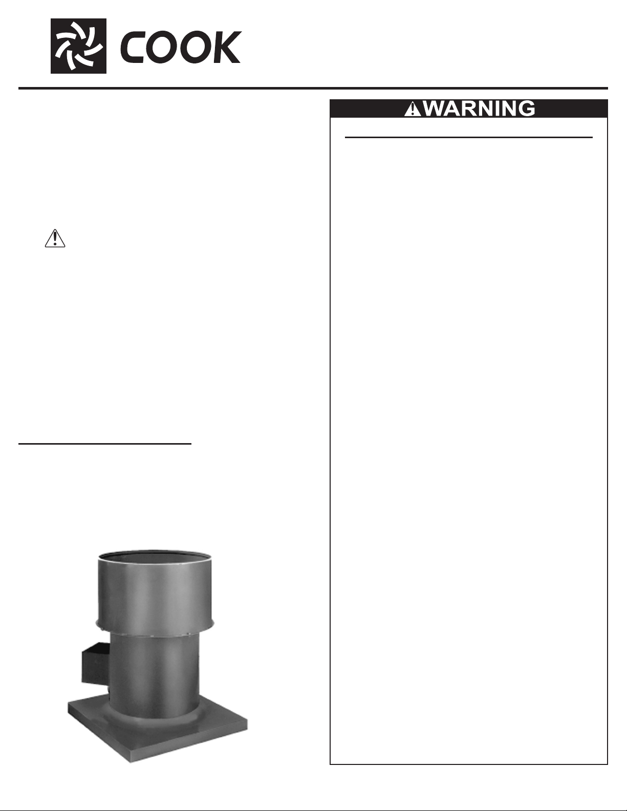
PROPELLER UPBLAST
INSTALLATION, OPERATION AND MAINTENANCE MANUAL
This publication contains the installation, operation and
maintenance instructions for standard units of the Upblast:
Upblast Propeller Roof Fans.
• LXUL & LXUM
• LTU
• LEU
• LXULMO &
LXUMMO
• LTU M O
Carefully read this publication and any
supplemental documents prior to any
installation or maintenance procedure.
Loren Cook catalogs, Propeller Upblast and Propeller Roof,
provide additional information describing the equipment, fan
performance, available accessories and specication data.
For additional safety information, refer to AMCA Publication
410 -9 6 , Safety Practices for Users and Installers of Industrial
and Commercial Fans.
All of the publications listed above can be obtained from:
• lorencook.com
• info@lorencook.com
• 417-869-6474 ext. 166
For information and instructions on special equipment, con-
tact Loren Cook Company at 417-869-6474.
• LEUMO
• TUB
• EUB
• AUB
• TUD
• EUD
• AUD
• SUB
• SUBH
• AI Upblast
Upblast Propeller Roof Fans
Rotating Parts & Electrical Shock Hazard:
Fans should be installed and serviced by qualied personnel
only.
Disconnect electric power before working on unit (prior to removal of guards or entry into access doors).
Follow proper lockout/tagout procedures to ensure the unit
cannot be energized while being installed or serviced.
A disconnect switch should be placed near the fan in order that
the power can be swiftly cut o, in case of an emergency and
in order that maintenance personnel are provided complete
control of the power source.
Grounding is required. All eld-installed wiring must be completed by qualied personnel. All eld installed wiring must
comply with National Electric Code (NFPA 70) and all applicable local codes.
Fans and blowers create pressure at the discharge and vacuum at the inlet. This may cause objects to get pulled into the
unit and objects to be propelled rapidly from the discharge.
The discharge should always be directed in a safe direction
and inlets should not be left unguarded. Any object pulled into
the inlet will become a projectile capable of causing serious injury or death.
Receiving and Inspection
Carefully inspect the fan and accessories for any damage
and shortage immediately upon receipt of the fan.
• Turn the propeller by hand to ensure it turns freely and does
not bind
• Check dampers (if included) for free operation of all moving
parts
• Record on the Delivery Receipt any visible sign of damage
TUB
When air is allowed to move through a non-powered fan,
the impeller can rotate, which is referred to as windmilling.
Windmilling will cause hazardous conditions due to unexpected rotation of components. Impellers should be blocked in position or air passages blocked to prevent draft when working
on fans.
Friction and power loss inside rotating components will cause
them to be a potential burn hazard. All components should be
approached with caution and/or allowed to cool before contacting them for maintenance.
Under certain lighting conditions, rotating components may
appear stationary. Components should be veried to be stationary in a safe manner, before they come into contact with
personnel, tools or clothing.
Failure to follow these instructions could result in death or serious injury.
The attachment of roof mounted fans to the roof curb as well
as the attachment of roof curbs to the building structure must
exceed the structural requirements based on the environmental loading derived from the applicable building code for the
site. The local code ocial may require variations from the recognized code based on local data. The licensed engineer of
record will be responsible for prescribing the correct attach-
ment based on construction materials, code requirements and
environmental eects specic to the installation.
1PROPELLER UPBLAST IO&M B51071-005
Page 2
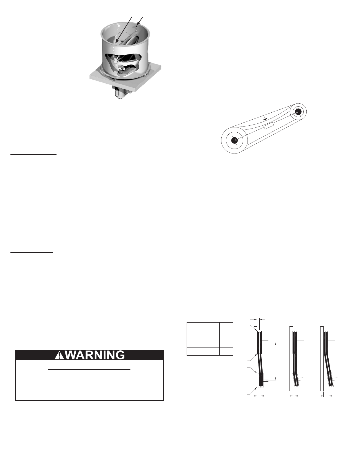
Handling
OFFSET ANGULAR OFFSET/ANGULAR
W
GAP
GAP
Lifting Lugs
Lift propeller roof ventila-
tors by lifting lugs located inside the wind band. Never lift
by the shaft, motor, propeller,
or coupling. If your fan has a
special protective nish, handle with extreme care. Even
a small chip will break the
coating’s continuity and destroy its ability to protect the
metal. Propellers are carefully
balanced to give smooth, vibration
free operation. If the propeller is dam-
aged during handling, it will require re-balancing.
Storage
If the fan is stored for any length of time prior to installation,
store it in its original shipping crate and protect it from dust,
debris and the weather.
Outdoor Storage
To maintain good working condition of the fan when it is
stored outdoors or at a construction site, follow the additional
instructions below.
• Coat the shaft and bearings with grease or rust preventative
compound to help seal out moisture
• Periodically rotate the propeller and operate the dampers (if
supplied) to keep a coating of grease on all internal bearing
parts
• Periodically inspect the fan to prevent damaging conditions
• Block propeller to prevent natural rotation
• Cover the unit with some type of weather cover to prevent
moisture, corrosion, dirt or dust accumulation
Installation
Damper Installation
1. Place the damper inside the curb. Ensure the damper will
open freely for the correct direction of the airow.
2. Secure to curb at the damper shelf by installing at least
two sheet metal screws (#10 x 1/2”) on each side of the
damper, through the tray, with the screw head catching
the ange on the damper. This will prevent the dampers
from lifting.
3. Drill a hole in the curb shelf for conduit needed for motor
wiring.
4. Operate the dampers manually to ensure the blades move
freely. Dampers should be released from full open position to check for proper closing.
An inlet guard is recommended. An inlet guard prevents
any large debris from being pulled into the fan and damaging the propeller. The inlet guard is installed on top of the
curb prior to the installation of the fan.
PROPELLER UPBLAST IO&M B51071-0052
Safety Recommendation
Motor Installation
To prevent damage to the fan during shipping, motors 5HP
and larger and extremely heavy motors (cast iron or severe
duty) are shipped loose and must be eld mounted.
The motor should be mounted so that the motor plate is
between the fan shaft and motor shaft.
• Remove the motor plate mounting bolts and the motor plate
• Remove the motor mounting bolts from the motor plate
• Mount the motor to the motor plate aligning to the appropriate holes
• Place the motor plate on the power assembly and rein-stall
the mounting bolts
1
/4
in
c
h
t
o
fo
1
Figure 1
Belt and Pulley Installation
If your fan is a direct drive (models AI, AUD, EUD and TUD),
proceed to Wiring Installation.
Belt tension is determined by the sound of the belts when
the fan is rst started. The belts will produce a loud squeal,
which dissipates after the fan is operating at full capacity. If
belt tension is too tight or too loose, lost eciency and damage can occur.
Do not change the pulley pitch diameter to change tension.
The change will result in a dierent fan speed.
• Loosen the motor plate adjustment nuts on motor base and
move motor plate in order that the belts can easily slip into
the grooves on the pulleys. Never pry, roll or force the belts
over the rim of the pulley
• Adjust the motor plate until proper tension is reached. For
proper tension, a deection of approximately 1/4” per foot of
center distance should be obtained by rmly pressing the
belt. Refer to Figure 1
• Lock the motor plate adjustment nuts in place
• Ensure pulleys are properly aligned. Refer to Figure 2
Tolerance
Center
Distance
Up through 12” 1/16”
12” through 48 1/8”
Over 48 1/4”
Max.
Gap
A
X
Y
CENTER
DISTANCE
(CD)
Figure 2
Z
B
Pulley Alignment
Pulley alignment is adjusted by loosening the motor pulley set-
screw and by moving the motor pulley on the motor shaft.
Figure 2 indicates where to measure the allowable gap for
the drive alignment tolerance. All contact points (indicated by
WXYZ) are to have a gap less than the tolerance shown in the
Page 3
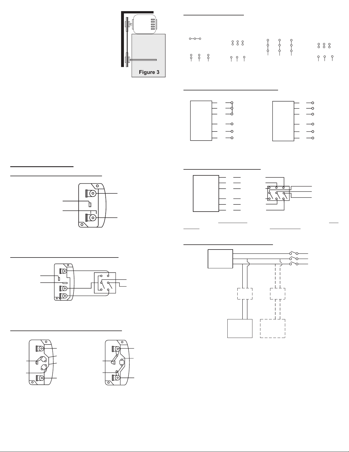
table. When the pulleys are not the same
T-
T-
Ground B
Line
Ground A
Ground B
T-
Line
Ground B
J-10
Ground A
Ground A
Line
Ground B
4
5
6
1
728
3
9
L
1
L2L
3
456
789
12
3
L
1
L2L
3
Low Voltage
208/230 Volts
High Voltage
460 Volts
3 Phase, 9 Lead Motor
Y-Connection
208/230 V
oltage
1
3
2
3 Phase, 9 Lead Motor
Delta-Connection
High Speed
3
Low Speed
Line
L
1
T
1
T
2
T
3
Low Speed
Low Speed
Low Speed
High Speed
High Speed
High Speed
Motor
T
13
T
12
T
11
L
2
Line
L
3
Motor
Tr
*
width, the allowable gap must be adjusted
by half of the dierence in width. Figure
3 illustrates using a carpenter’s square to
adjust the position of the motor pulley until
the belt is parallel to the longer leg of the
square.
Wiring Installation
All wiring should be in accordance with
local ordinances and the National Elec-
trical Code, NFPA 70. Ensure the power supply (voltage,
frequency, and current carrying capacity of wires) is in ac-
cordance with the motor nameplate. Refer to the Wiring Diagrams, on page 3.
Lock o all power sources before unit is wired to power
source.
Leave enough slack in the wiring to allow for motor movement when adjusting belt tension. Some fractional motors
have to be removed in order to make the connection with the
terminal box at the end of the motor.
Wiring Diagrams
Single Speed, Single Phase Motor
Ground A
3-Phase, 9 Lead Motor
Low Voltage
7
6
1
L
1
To reverse, interchange any two line leads.
olts
9
8
5
4
3
2
L
L
3
2
High V
460 Volts
789
456
12
L
L
3
L
2 Speed, 1 Winding, 3-Phase Motor
L
1
L
2
L
3
Open
Motor
1
Together
2
3
L
4
5
6
1
L
2
Line
L
Motor
1
2
3
4
5
6
To reverse, interchange any two line leads. Motors require magnetic
control.
2 Speed, 2 Winding, 3-Phase
L
1
1
4
L
2
When ground is required, attach to ground A or B with No. 6 thread
forming screw. To reverse, interchange T-1 and T-4.
2 Speed, 2 Winding, Single Phase Motor
High Speed
T-1
4
L
1
L
2
Low Speed
When ground is required, attach to ground A or B with No. 6 thread
forming screw. To reverse, interchange T-1 and T-4 leads.
Single Speed, Single Phase, Dual Voltage
L
1
T-5
When ground is required, attach to ground A or B with No. 6 thread
forming screw. To reverse, interchange T-5 and J-10 leads.
Link A
Link B
Low Voltage
L
2
Line
T-5
J-10
L
1
Link A
and B
L
2
To reverse, High Speed: interchange leads T11 and T12; Low
Speed: interchange leads T1 and T2; Both Speeds: interchange any
two line leads.
Typical Damper Motor Schematic
Fan
Motor
ansformer**
Damper
Motor*
Second
Damper
Transformer*
For 3-Phase, damper motor voltage should be the same between L1
and L2. For single phase application, disregard L3.
*Damper motors may be available in 115, 230 and 460 volt models. The damper motor nameplate voltage should be veried prior to
connection.
**A transformer may be provided in some installations to correct the
damper motor voltage to the specied voltage.
L3
L2
L1
Follow the wiring diagram in the disconnect switch and
the wiring diagram provided with the motor. Correctly la-
bel the circuit on the main power box and always identify a
closed switch to promote safety (i.e., red tape over a closed
switch).
3PROPELLER UPBLAST IO&M B51071-005
Page 4
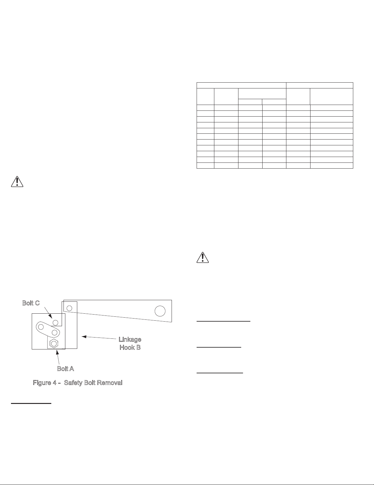
Fan Installation
Figure 4 - Safety Bolt Removal
The fan support (roof curb) should provide a level surface
for installation. If the roof is pitched more than 1/2:12, a sloped
curb must be used to correct for the incline. If the unit is in-
stalled on a non-level surface, the damper door pivot should
be positioned perpendicular to the peak of the roof. Consult
factory for additional details.
• Place fan over roof opening
• Secure the fan with lag screws, anchor bolts, or other suit-
able fasteners
Final Installation Steps
1. Inspect fasteners and setscrews, particularly fan mount-
ing and bearing fasteners, and tighten according to the
recommended torque shown in the table, Recommended
Torque for Setscrews/Bolts.
2. Inspect for correct voltage with voltmeter.
3. Ensure all accessories are installed.
4. Test the fan to be sure the rotation is the same as indicat-
ed by the arrow marked Rotation.
Do not allow the fan to run in the wrong direction. This
will overheat the motor and cause serious damage.
For 3-phase motors, if the fan is running in the wrong
direction, check the control switch. It is possible to
interchange two leads at this location so that the fan is
operating in the correct direction.
Smoke Control Units Additional Installation Steps
The damper actuator arms are safety bolted at the factory
to prevent damage or personnel injury during handling and installation. The bolt must be removed for the damper actuator
to operate correctly. Refer to Figure 4.
• Remove Bolt “A” from each of the damper arms
• Be sure that linkage hook “B” is in contact with bolt “C” to
prevent excessive load on the fusible link
The damper arms will not operate unless this bolt is removed. This bolt should be replaced before any maintenance
or repair work is started.
Bolt C
Linkage
Hook B
Bolt A
3. Inspect motor wiring.
4. Ensure the belt touches only the pulleys.
5. Rotate the propeller to ensure it does not rub against the
base.
6. Ensure fan and ductwork are clean and free of debris.
7. Test the fan to ensure the rotation of the propeller is the
same as indicated by the rotation label.
8. Close and secure all access doors.
9. Restore power to unit.
Recommended Torque for Setscrews/Bolts (IN-LB)
Setscrews Hold Down Bolts
Key Hex
Size
Across
Flats
#8 5/64” 15 21 3/8”-16 324
#10 3/32” 27 33 1/2”-13 780
1/4 1/8” 70 80 5/8”-11 1440
5/16 5/32” 140 160 3/4”-10 2400
3/8 3/16” 250 290 7/8”-9 1920
7/16 7/32” 355 405 1”-8 2700
1/2 1/4” 560 640 1-1/8”-7 4200
5/8 5/16” 1120 1280 1-1/4”-7 6000
3/4 3/8” 1680 1920 - 7/8 1/2” 4200 4800 - -
1 9/16” 5600 6400 - -
Recommended
Tor q u e
Min. Max.
Size
Recommended
Tor q u e
Start Up
Turn the fan on. In variable speed units, set the fan to its
lowest speed. Inspect for the following:
• Direction of rotation
• Excessive vibration
• Unusual noise
• Bearing noise
• Improper belt alignment or tension (listen for a continuous
squealing noise)
• Improper motor amperage or voltage
If a problem is discovered, immediately shut o the
fan. Lock out all electrical power and check for the
cause of the trouble. Refer to Troubleshooting.
Inspection
Inspection of the fan should be conducted at the rst
30-minute, 8-hour and 24-hour intervals of satisfactory op-
eration. During the inspections, stop the fan and inspect as
per the information below.
30-Minute Interval:
Inspect bolts, setscrews, and motor mounting bolts. Adjust
and tighten as necessary.
8-Hour Interval
Inspect belt alignment and tension. Adjust and tighten as
necessary.
24-Hour Interval
Inspect belt tension. Adjust and tighten as necessary.
Operation
Pre-Start Checks
1. Lock out all the primary and secondary power sources.
Inspect fasteners and setscrews, particularly those used
for mounting the unit, and tighten if necessary.
2. Inspect belt tension and pulley alignment. (Remember, if belt
tension is correct, a loud squeal occurs as the fan increases
to full power.)
PROPELLER UPBLAST IO&M B51071-0054
Maintenance
Establish a schedule for inspecting all parts of the fan. The
frequency of inspection depends on the operating conditions
and location of the fan.
Inspect fans exhausting corrosive or contaminated air within
the rst month of operation. Fans exhausting contaminated air
(airborne abrasives) should be inspected every three months.
Clean the propeller and air inlets if material build-up is excessive. Excessive build-up can cause imbalance and failure of
the propeller.
Page 5

Regular inspections are recommended for fans exhausting
non-contaminated air.
It is recommended the following inspections be con-
ducted twice per year.
• Inspect bolts and setscrews for tightness. Tighten as
necessary
• Inspect belt wear and alignment. Replace worn belts with
new belts and adjust alignment as needed. See Belt and Pul-
ley Installation, page 2
• Bearings should be inspected as recommended in the Conditions Chart
• Inspect for cleanliness. Clean exterior surfaces only. Removing dust and grease on motor housing assures proper motor
cooling
Lubricants
Loren Cook Company uses petroleum lubricant in a lithium
base conforming to NLGI grade 2 consistency. Other grades
of grease should not be used unless the bearings and lines
have been ushed clean. If another grade of grease is used, it
should be lithium-based.
An NLGI grade 2 grease is a light viscosity, low-torque,
rust-inhibiting lubricant that is water resistant. Its temperature range is from -30°F to +200°F and capable of intermittent
highs of +250°F.
Motor Bearings
Motors are provided with prelubricated bearings. Any lubri-
cation instructions shown on the motor nameplate supersede
instructions below.
Motor bearings without provisions for relubrication will op-
erate up to 10 years under normal conditions with no mainte-
nance. In severe applications, high temperatures or excessive
contaminates, it is advisable to have the maintenance depart-
ment disassemble and lubricate the bearings after 3 years of
operation to pre-vent interruption of service.
For motors with provisions for relubrication, follow intervals
of the table below.
Relubrication Intervals
NEMA Frame Size
213T–365T 404T and larger
1800
RPM
and less
3
6 months
1800 RPM
1 yr. 3 months 6 months
Over
1-1/2
months
1800
Over 1800
RPM
and less
3 months 2 weeks
RPM
1-1/2
months
Service
Conditions
Standard 1-1/2 yrs.
Severe 6 months
including 184T
1800 RPM
and less
Up to and
months
months
Over
1800
RPM
1-1/2
Motors are provided with a polyurea mineral oil NGLI #2
grease. All additions to the motor bearings are to be with
a compatible grease such as Exxon Mobil Polyrex EM and
Chevron SRI.
Fan Bearings
Fan bearings are lubricated through a grease connector and
should be lubricated by the schedule, Conditions Chart, below
Conditions Chart
RPM Tem p °F Greasing Interval
Up to 1000
1000 to 3000
Over 3000
Any Speed < -30 Consult Factory
Any Speed > 200 1 week
-30 to 120 6 months
120 to 200 2 months
-30 to 120 3 months
120 to 200 1 month
-30 to 120 1 month
120 to 200 2 weeks
For best results, lubricate the bearing while the fan is rotating. Slowly pump grease into the bearing until a slight bead
forms around the bearing seals. Excessive grease can burst
seals thus reduce bearing life.
In the event the bearing cannot be seen, use no more than
three injections with a hand-operated grease gun.
Motor Services
Should the motor prove defective within a one-year period,
contact your local Loren Cook representative or your nearest
authorized electric motor service representative.
Changing Shaft Speed
All belt driven propeller roof fans with motors up to and in-
cluding 5HP are equipped with variable pitch pulleys. To
change the fan speed, perform the following:
• Loosen setscrew on driver (motor) pulley and remove key,
if equipped
• Turn the pulley rim to open or close the groove facing. If
the pulley has multiple grooves, all must be adjusted to the
same width
• After adjustment, inspect for proper belt tension
Speed Reduction
Open the pulley in order that the belt rides deeper in the
groove (smaller pitch diameter).
Speed Increase
Close the pulley in order that the belt rides higher in the
groove (larger pitch diameter). Ensure that the RPM limits of
the fan and the horsepower limits of the motor are maintained.
Maximum RPM
LXUL
AI Ublast
Max.
Size
RPM
20 1270
24 1110
30 930
36 720
42 600
48 508
54 478
60 450
Size
Max.
RPM
31 3500
36 3500
41 3500
47 3500
54 3500
63 2360
72 2360
80 2360
90 2360
103 2271
113 178 8
123 1560
140 1492
160 1300
LXUM
Size
20 14 60
24 140 0
30 117 0
36 860
42 718
48 598
54 522
60 476
AUB
Size
24 1585
30 118 0
36 1015
42 935
48 845
LTU
Size
20 2361
24 1964
30 15 81
36 1314
42 110 6
48 973
54 829
60 767
Max.
RPM
Max.
RPM
Max.
RPM
LEU Size
20 1675
24 165 0
30 135 0
36 1310
42 1210
48 1214
54 946
60 854
LXUM
Size
24 1650
30 13 05
36 13 05
42 120 0
48 115 0
54 900
60 870
72 688
TUB, SUB,
SUBH Size
20 2633
24 1993
30 1605
36 1314
42 1106
48 973
54 888
60 783
72 616
Max.
RPM
Max.
RPM
Max.
RPM
5PROPELLER UPBLAST IO&M B51071-005
Page 6

Pulley and Belt Replacement
1. Clean the motor and fan shafts.
2. Loosen the motor plate mounting bolts to relieve the belt
tension. Remove the belt.
3. Loosen the pulley setscrews and remove the pulleys from
the shaft. If excessive force is required to remove the pul-
leys, a three-jaw puller can be used. This tool, however,
can easily warp a pulley. If the puller is used, inspect the
trueness of the pulley after it is removed from the shaft.
The pulley will need replacement if it is more than 0.020
inch out of true.
4. Clean the bores of the pulleys and place a light coat of oil
on the bores.
5. Remove grease, rust and burrs from the shaft.
6. Place fan pulley on the fan shaft and the motor pulley on
the motor shaft. Damage to the pulleys can occur when
excessive force is used in placing the pulleys on their respective shafts.
7. After the pulleys have been correctly placed back onto
their shafts, tighten the pulley setscrews.
8. Install the belts on the pulleys. Align and adjust the belts
to the proper tension as described in Belt and Pulley In-
stallation, page 2.
Bearing Replacement
1. The fan bearings are pillow block ball bearings.
2. Remove the wind band and damper assembly to gain access to the fan.
3. Loosen the motor plate mounting bolts and remove the
drive belts.
4. Remove the propeller from the shaft.
5. Remove the bearing cover. Remove the four (4) bearing
hold-down bolts and then remove the shaft, bearings, and
driven sheave from the unit as an assembly.
6. Measure and record the location of the bearings and
sheave on the shaft. This will aid the reassembly.
7. Remove the anti-corrosion coating from the shaft with a
suitable degreaser and then remove the pulley from the
shaft. An emer y cloth or le may be needed to remove imperfections in the shaft left by the setscrews.
8. Remove the bearing from the shaft using a bearing puller.
9. Clean the shaft and bearing bores thoroughly.
10. Place the bearings into position making sure they are not
on a worn section of the shaft. Tapping the inner ring face
with a soft driver may be required. Tighten the setscrews
on the lower bearing.
11. Install the pulley in the correct location on the shaft. Se-
cure the bearing hold-down bolts, but do not fully tighten.
12. Align the setscrews on the top bearing with those on the
lower bearing. Tighten one of them.
13. Rotate the shaft to allow the bearing outer rings to nd
their center of free movement. If your fan is supplied with
a lube line, attach it to the grease connection.
14. Install the propeller on the shaft and adjust bearing position to center the propeller in the opening.
15. Tighten hold-down bolts to proper torque. Refer to Rec-
ommended Torque Chart, page 4.
16. Turn the shaft by hand. Resistance should be the same as
it was before hold-down bolts were fully tightened.
17. Tighten bearing setscrews to specied torque.
18. Reassembly the fan.
After 24 hours of continuous operation, tighten the set-
screws to the appropriate torque. This assures the full locking
of the inner race to the shaft. Ensure the socket key or driver
is in good condition with no rounded corners. The key should
be fully engaged in the setscrew and held squarely to prevent
the rounding out of the setscrew socket when applying maximum torque.
Propeller and Shaft Replacement Precautions
• If the shaft is dropped and bent, it may cause unbalanced
operation of the fan
• When handling the propeller separately from the shaft,
place a support through the hub for lifting, making sure not
to injure the nished bore of the propeller
• Never allow the propeller to rest its entire weight on the
blades. The propeller and shaft can be lifted by slings
around the shaft on each side of the propeller so the propeller is supported by its hub
• If using a chain to lift the propeller, make sure there is sucient padding on the shaft and propeller. This prevents the
scoring of the shaft or injury to the propeller. The chain or
cable should be spread with timbers, or braced by some
other method to prevent damage to the propeller side plates
Troubleshooting
Problem and Potential Cause
Low Capacity or Pressure:
• Incorrect direction of rotation. Make sure the fan rotates
in same direction as the arrows on the motor or belt drive
assembly
• Poor fan inlet conditions. There should be a straight clear
duct at the inlet
• Improper propeller alignment
Excessive Vibration and Noise:
• Damaged or unbalanced propeller
• Belts too loose; worn or oily belts
• Speed too high
• Incorrect direction of rotation. Make sure the fan rotates
in same direction as the arrows on the motor or belt drive
assembly
• Bearings need lubrication or replacement
• Fan surge
Overheated Motor:
• Motor improperly wired
• Incorrect direction of rotation. Make sure the fan rotates
in same direction as the arrows on the motor or belt drive
assembly
• Cooling air diverted or blocked
• Improper inlet clearance
• Incorrect fan RPMs
• Incorrect voltage
Overheated Bearings:
• Improper bearing lubrication
• Excessive belt tension
PROPELLER UPBLAST IO&M B51071-0056
Page 7

AUD / EUD / TUD Parts List
Parts Numbers
AUD/EUD/TUD
10
9
8
1
2
3
4
Part
No.
AUD (Sizes 24 - 48) EUD (Sizes 20 - 60) TUD (Sizes 20 - 60)
1 Damper Stop Damper Stop Damper Stop
2 Rubber Bumper(2) Rubber Bumper(2) Rubber Bumper(2)
3 Wind Band Wind Band Wind Band
Cast Aluminum
4
5 Power Assembly Power Assembly Power Assembly
6 Motor Plate Motor Plate Motor Plate
7
8 Motor Motor Motor
9
10 Damper Assembly Damper Assembly Damper Assembly
Propeller
Lower Drum
Assembly
Damper Rubber
Extr usion (2)
Description
Aluminum Propeller Tri t o n® Propeller
Lower Drum
Assembly
Damper Rubber
Extr usion (2)
Lower Drum
Assembly
Damper Rubber
Extr usion (2)
5
6
7
SUB/SUBH/TUB with Smoke Control
2
11
1
10
20
19
18
17
16
15
14
12
13
Part
No.
SUB/TUB (Sizes 24 - 72) SUBH (Sizes 24 - 72)
1 Damper Backstop Damper Backstop Damper Backstop
2 Rubber Bumper (2) Rubber Bumper (2) Rubber Bumper (2)
3 Damper Rubber Extrusion Damper Rubber Extrusion Damper Rubber Extrusion
Weather Cover Rubber
4
3
4
5
8
9
5 Motor Plate Motor Plate Motor Plate
6 Weather Cover Weather Cover Weather Cover
7 Motor Motor Motor
8 Driver Sheave Driver Sheave Driver Sheave
9 Belt Set Belt Set Belt Set
10 Split Locking Collar Split Locking Collar Split Locking Collar
11 Driven Sheave Driven Sheave Driven Sheave
12 Bearings (2) Bearings (2) Bearings (2)
13 Bearing Cover Bearing Cover Bearing Cover
14 Lower Drum Assembly Lower Drum Assembly Lower Drum Assembly
6
15 Shaft Shaft Shaft
7
16 Heat Slinger (optional) Heat Slinger (optional) Heat Slinger
17 Steel Propeller Steel Propeller Tr i t o n® Propeller
18
19 Wind Band Assembly Wind Band Assembly Wind Band Assembly
20 Damper Assembly Damper Assembly Damper Assembly
Extrusion
Spring Loaded Damper
(optional)
Description
TUB with Smoke Control
(Sizes 24 - 72)
Weather Cover Rubber
Extrusion
Spring Loaded Damper Spring Loaded Damper
Weather Cover Rubber
Extrusion
7PROPELLER UPBLAST IO&M B51071-005
Page 8

EUB/AUB
EUB Sizes 24–72
18
17
16
15
1
2
3
4
5
6
8
Part
No.
1 Damper Backstop Damper Backstop
2 Rubber Bumper (2) Rubber Bumper (2)
3 Damper Rubber Extrusion (2) Damper Rubber Extrusion (2)
4 Shaft Shaft
5 Weather Cover Rubber Extrusion Weather Cover Rubber Extrusion
6 Motor Plate Motor Plate
7 Weather Cover Weather Cover
8 Motor Motor
9 Driver Sheave Driver Sheave
10 Belt Set Belt Set
11 Split Locking Collar Split Locking Collar
12 Driven Sheave Driven Sheave
13 Bearings (2) Bearings (2)
14 Bearing Cover Bearing Cover
15 Lower Drum Assembly Lower Drum Assembly
7
16 Extruded Aluminum Cast Aluminum
17 Wind Band Assembly Wind Band Assembly
18 Damper Assembly Damper Assembly
EUB (Sizes 24 - 72) AUB (Sizes 24 - 48)
Description
9
14
13
AUB Sizes 24–48
18
17
16
15
12
11
1
2
10
3
4
5
6
7
9
8
14
13
PROPELLER UPBLAST IO&M B51071-0058
12
11
10
Page 9

LEU Parts List
LXUL/LXUM
15
14
17
16
18
13
12
19
11
1
3
2
Part
No.
4
5
10 Belt Belt
6
7
8
11 Driven Sheave Driven Sheave
12 - Locking Collar
13 Bearing (2) Bearing (2)
14 Shaft Shaft
15 Rain Gutter Rain Gutter
16
17
18
19
9
LXUL/LXUM Description
Size 20-36 Size 42-60
Damper Stop
1
Bracket (2)
Damper Stop
2
Channel
3
4 Windband Windband
5
6 Base Weldment Base Weldment
7 Motor Plate Motor Plate
8 Motor Motor
9 Drive Sheave Drive Sheave
Damper
Bumper (2)
X.STREAM
Propeller
Damper Door
(2)
Damper Hinge
(4)
Damper Pivot
Rod
Damper Pivot
Bracket
Damper Stop
Bracket (2)
Damper Stop
Channel
Damper
Bumper (2)
X.STREAM
Propeller
Damper Door
(2)
Damper Hinge
(8)
Damper Pivot
Rod
Damper Pivot
Bracket
10
LEU
18
17
16
15
14
12
13
19
11
1
3
2
4
5
6
7
8
10
9
Part
No.
Damper Stop Bracket
1
2
3 Damper Bumper (2) Damper Bumper (2)
4 Windband Windband
5 Extruded Propeller Extruded Propeller
6 Base Weldment Base Weldment
7 Motor Plate Motor Plate
8 Motor Motor
9 Drive Sheave Drive Sheave
10 Belt Belt
11 Driven Sheave Driven Sheave
12 - Locking Collar
13 Bearing (2) Bearing (2)
14 Shaft Shaft
15 Rain Gutter Rain Gutter
16 Damper Door (2) Damper Door (2)
17 Damper Hinge (4) Damper Hinge (8)
18 Damper Pivot Rod Damper Pivot Rod
19
Damper Stop
Damper Pivot
Brackets (2)
LEU Description
Size 20-36 Size 42-60
(2)
Channel
Damper Stop Bracket
(2)
Damper Stop
Channel
Damper Pivot
Brackets (2)
9PROPELLER UPBLAST IO&M B51071-005
Page 10

LTU
15
14
13
12
11
1
2
3
4
1716
18
19
5
6
Part No. Description
1 Damper Stop Bracket
2 Damper Stop Channel
3 Damper Bumper (2)
4 Windband
5 TRITON® Propeller
6 Base Weldment
7 Motor Plate
8 Motor
9 Drive Sheave
10 Belt
11 Driven Sheave
12 Locking Collar
13 Bearings (2)
14 Shaft
15 Rain Gutter
16 Damper Door (2)
17 Damper Hinge
18 Damper Pivot Rod
19 Damper Pivot Bracket
7
8
9
10
LXULMO/LXUMMO
21
17
16
15
14
13
12 11
18
10
19
3
2
1
4
22
5
20
6
7
8
9
Part
No.
LXULMO/LXUMMO With Smoke Control
1 Damper Stop Bracket Damper Stop Bracket
2 Damper Stop Channel Damper Stop Channel
3 Damper Bumper (2) Damper Bumper (2)
4 Windband Windband
X.STREAM Series
5
6 Shaft Shaft
7 Bearing Cover Bearing Cover
8 Bearings (2) Bearings (2)
9 Driven Sheave Driven Sheave
10 Belt Set Belt Set
11 Motor Plate Motor Plate
12 Drive Sheave Drive Sheave
13 Motor Motor
14 Motor Cover Motor Cover
15 Lower Drum Weldment Lower Drum Weldment
16 Damper Pivot Bracket Damper Pivot Bracket
17 Damper Hinge Damper Hinge
18 Damper Pivot Rod Damper Pivot Rod
19 Belt Tunnel (Optional) Belt Tunnel
20 - Heat Slinger
21 Damper Doors (2) Damper Doors (2)
22 - Fire Damper Assembly
Propeller
Description
X.STREAM Series
Propeller
PROPELLER UPBLAST IO&M B51071-00510
Page 11

LTUMO
14
13
12 11
16
15
17
21
18
10
19
3
2
1
4
22
5
20
6
7
8
Part
No.
1 Damper Stop Bracket Damper Stop Bracket
2 Damper Stop Channel Damper Stop Channel
3 Damper Bumper (2) Damper Bumper (2)
4 Windband Windband
5 TRITON® Propeller TRITON® Propeller
6 Shaft Shaft
7 Bearing Cover Bearing Cover
8 Bearings (2) Bearings (2)
9 Driven Sheave Driven Sheave
10 Belt Set Belt Set
11 Motor Plate Motor Plate
12 Drive Sheave Drive Sheave
13 Motor Motor
14 Motor Cover Motor Cover
15 Lower Drum Weldment Lower Drum Weldment
16 Damper Pivot Bracket Damper Pivot Bracket
17 Damper Hinge Damper Hinge
18 Damper Pivot Rod Damper Pivot Rod
19 Belt Tunnel (Optional) Belt Tunnel
20 - Heat Slinger
21 Damper Doors (2) Damper Doors (2)
22 - Fire Damper Assembly
LTU M O With Smoke Control
Description
9
LEUMO
14
13
12 11
16
15
17
18
10
2
1
3
4
5
Part No. Description
1 Damper Stop Bracket
2 Damper Stop Channel
3 Damper Bumper (2)
4 Windband
5 E Series Propeller
6 Shaft
7 Bearing Cover
8 Bearings (2)
9 Driven Sheave
10 Belt Set
11 Motor Plate
12 Drive Sheave
13 Motor
14 Motor Cover
15 Lower Drum Weldment
16 Damper Pivot Bracket
6
17 Damper Hinge
18 Damper Pivot Rod
7
8
9
11PROPELLER UPBLAST IO&M B51071-005
Page 12

AI Upblast
1
3
Part No. Description
1 Damper Stop Assembly
4
2
2 Damper Assembly
3 Lifting Lugs
4 Windband
5 AI Propeller
5
6 AI Vertical Housing
7 Curb Cap
8 Motor
6
8
7
Limited Warranty
Loren Cook Company warrants that your Loren Cook fan was manufactured free of defects in materials and workmanship, to the extent stated herein.
For a period of one (1) year after date of shipment, we will replace any parts found to be defective without charge, except for shipping costs which will be
paid by you. This warranty is granted only to the original purchaser placing the fan in service. This warranty is void if the fan or any part thereof has been
altered or modied from its original design or has been abused, misused, damaged or is in worn condition or if the fan has been used other than for the
uses described in the company manual. This warranty does not cover defects resulting from normal wear and tear. To make a warranty claim, notify Loren
Cook Company, General Oces, 2015 East Dale Street, Springeld, Missouri 65803-4637, explaining in writing, in detail, your complaint and referring to
the specic model and serial numbers of your fan. Upon receipt by Loren Cook Company of your written complaint, you will be notied, within thirty (30)
days of our receipt of your complaint, in writing, as to the manner in which your claim will be handled. If you are entitled to warranty relief, a warranty ad-
justment will be completed within sixty (60) business days of the receipt of your written complaint by Loren Cook Company. This warranty gives only the
original purchaser placing the fan in ser vice specically the right. You may have other legal rights which vary from state to state.
Corporate Oces: 2015 E. Dale St. Springeld, MO 65803
Phone 417-869-6474 | Fax 417-862-3820 | lorencook.com
June 2019
PROPELLER UPBLAST IO&M B51071-00512
 Loading...