

Page 1
Laboratory Exhaust
Vari-Plume® and Laboratory Exhaust Products
SUPPLEMENTAL INSTALLATION AND MAINTENANCE MANUAL
This publication contains supplemental installation and
maintenance instructions for Vari-Plume
Exhaust units:
• CPSLE • QMXLE • TCNHBLE
• CAVP • QMXVP
Carefully read this publication prior to any installation or
maintenance procedure. Refer to the appropriate Installation,
Operation, and Maintenance Manual for items not specifically
covered here, such as handling, storage, start-up, etc.
Loren Cook brochure, Vari-Plume
vides additional information describing the equipment, fan perfo rmance, available accessories, and specification data.
For additional safety information, refer to AMCA Publication
410-96, Safety Practices for Users and Installers of Industrial and
Commercial Fans.
WARNING
This unit has rotating parts. Safety preca utions sho uld
be exercised at all times during installation, operation,
and maintenance.
ALWAYS disconnect power prior to working on fan.
®
®
and Laboratory
Laboratory Exhaust, pro-
Handling and Lifting
Always lift fan by lifting lugs. Never lift unit by shaft, motor,
housing, or nozzle.
The units may be shipped in sections and each section should
be lifted into place using the provided lifting lugs. If the unit is to
be lifted assembled, lift the unit with lifting lugs attached to the fan
housing using a spreader bar as required to ensure no damage is
incurred on the nozzle assembly.
All Vari-Plume® and Laboratory Exhaust units are designed to
be self-supporting, without the use of guy wire, when installed
according to the instructions within this document. The roof curb
must be securely installed prior to fan installation according to the
curb manufacturer’s recommendations.
Unit Assembly
If unit is shipped in sections, assemble unit starting at the low-
est level moving up the assembly. Each section should have a
pre-installed gasket that must be present to ensure proper sealing
of unit. If the gasket is damaged or missing, caulk may be used to
seal the sections by applying between the bolted sections. Once
the gasket/caulk has been verified, assemble the sections and
bolt together with the provided ha rd w are .
Installation
The unit should be installed on a curb/base that is securely
attached to the roof structure per contract documents and local
codes. If the curb is provided by Loren Cook, the curb should be
attached per the provided submittal document by welding to the
roof structure.
For curb mounted assemblies, the unit should be securely fas-
tened to the curb using minimum ¼” x ¾” sheet metal screws
using pre-punched holes in the curb cap. If pre-punch ed holes
are not provided, use a minimum of 2 screws per side and a maximum of 12” spacing.
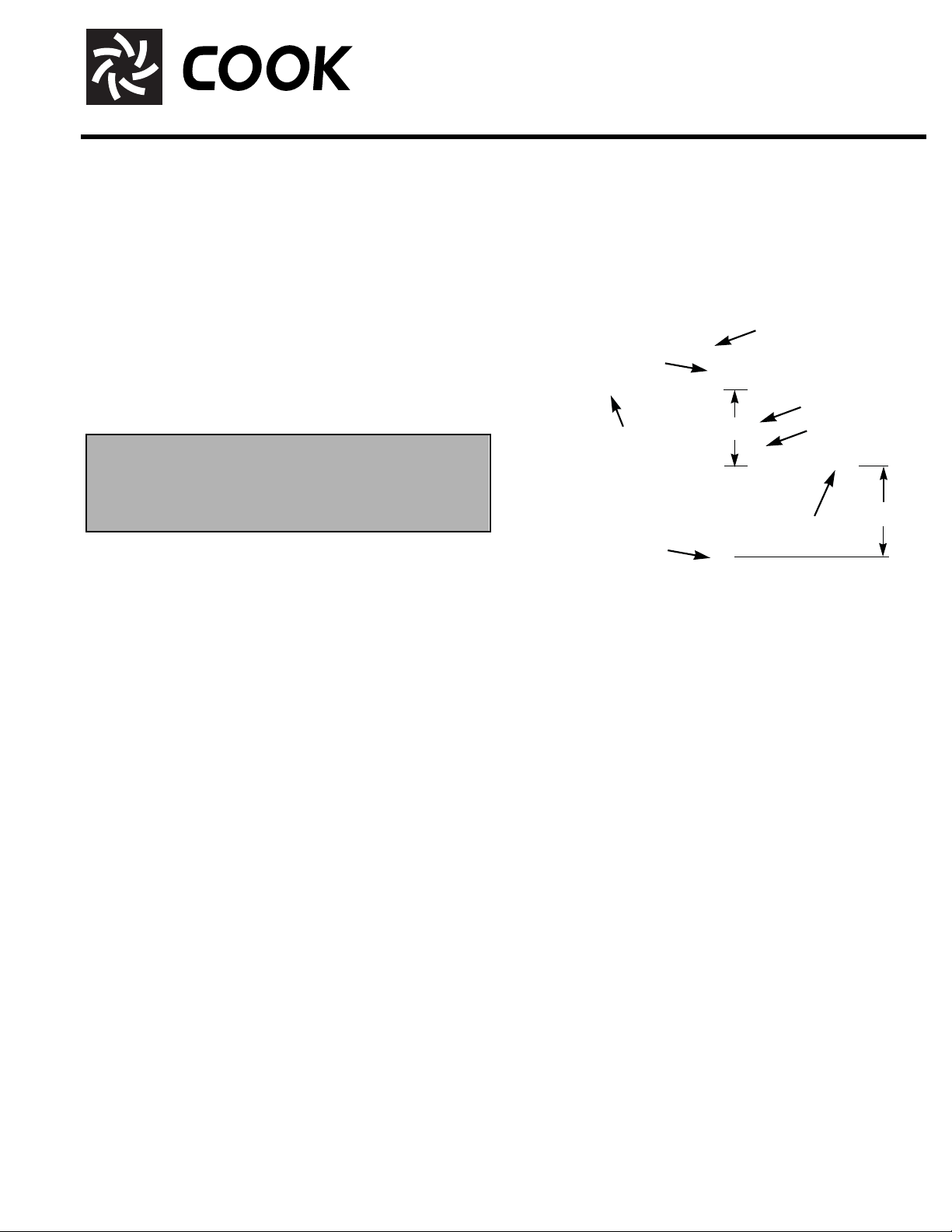
Drain Connections
Loren Cook lab exhaust fans all have drains as standard construction features. These drains should be properly connected
to a drainage system to ensure that the run off from the units is
disposed of properly. The connection should include a trap system (Figure 5) that is sized adequately to not allow for air leakage under the system pressure. Dimension A and B should be
double the total static pressure for the unit.
FIGURE 5
Finger-Tight Plug
Clean Out
Finger-Tight Plug
B
CPSLE
CAVP
Drain Pipe
Drain Trap
QMXVP
(6" Min)
QMXLE
Clean Out
Slope To
Drain
TCNHBLE
A
(6" Min)
Page 2
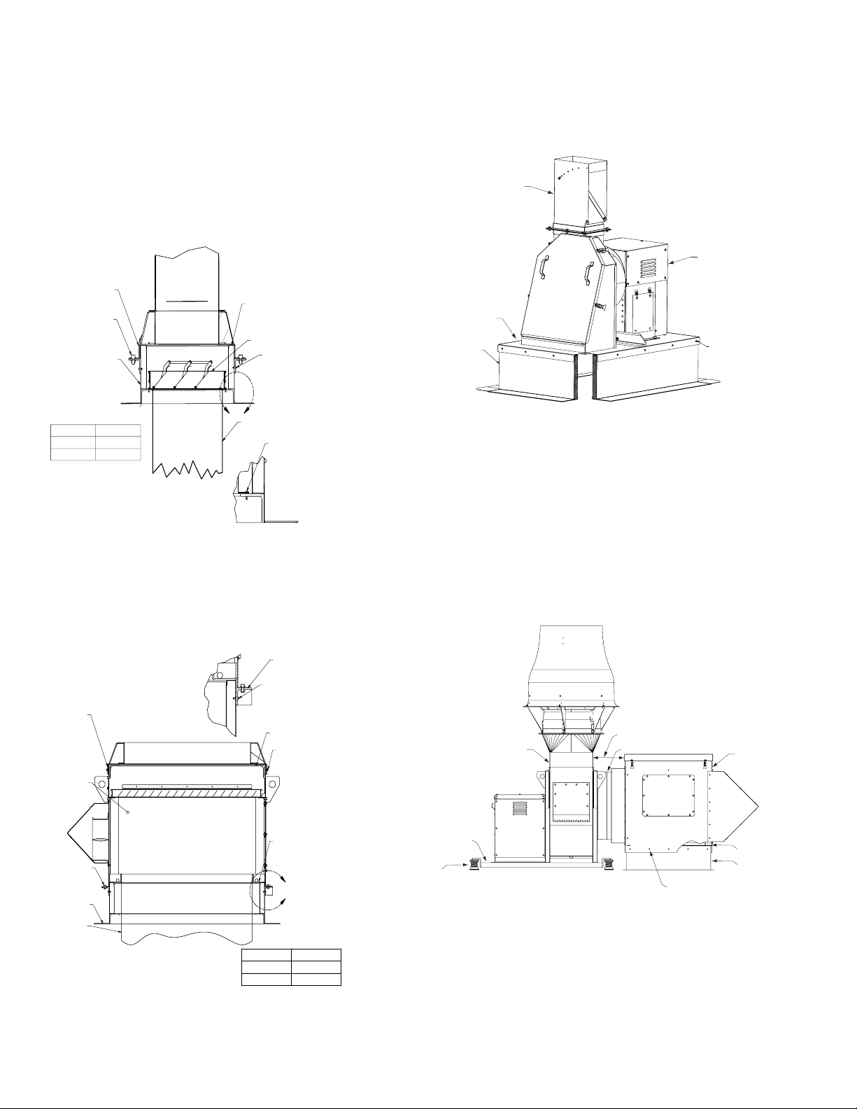
Typical Installations
QMXVP QMXLE, TCNHBLE
Typical installations for QMXVP, QMXLE, and TCNHBLE
are shown below utilizing the Loren Cook LE curb. Figure 1
shows a unit without mixing box and an optional curb mounted
isolation damper. The curb should be secured to the roof
structure per project documents and then the isolation damper
mounted in the curb as required. Ensure that the curb gasket
is present and not damaged once the curb has been p roperly
installed on the roof. Then the unit should be installed on the
curb using the supplied mounting brackets and recommended
fasteners.
CURB CAP
PVC GASKET
3/8-16 STAINLESS
STEEL BOLT
LE CURB
ISOLATION DAMPER
A x 3/4”
SELF TAPPING SHEET
METAL SCREWS
(BY OTHERS)
CPSLE
Figure 3 shows a typical CPSLE installation on a Cook RCG
curb. The RCG curb should be securely mounted to the roof per
project documents. Ensure that the curb gasket is in place once
the curb has been installed on the roof. The unit should then be
installed on the curb using the fasteners recommended in figure
3, Use a minimum of 2 screws per side and a maximum of 12”
spacing.
NOZZLE
CPSLE UNIT
CURB CAP
1/4" SELF-TAPPING
LOREN COOK
RCGH CURB
SHEET METAL
SCREWS
(BY OTHERS)
C
SIZE A
60-330 1/4
365+ 3/8
FIGURE 1
DUCT WORK
SELF TAPPING SHEET
METAL SCREWS
(BY OTHERS)
DETAIL C
Figure 2 shows a typical installation using a mixing box/
plenum and the Loren Cook LE curb. Similar to above the
curb should be installed first per project documents and then
the unit installed on the curb using recommended fasteners.
DETAIL B
ANGLE
FRAME
A x 3/4”
SELF-TAPPING
SHEET METALS SCREWS
CURB CAP
MIXING BOX
(BY OTHERS)
PVC
GASKET
3/8-16 STAINLESS
STEEL BOLT
FIGURE 3
CAVP
A typical installation for a CAVP with mixing box is shown in
figure 4. The CAVP unit is installed on either isolation rails or
base as defined in the project documents. This unit is then
installed on the roof using the correct vibration isolators per the
isolator installation instructions. The mixing box is installed on a
roof curb using the fasteners recommended in figure 4 and the
roof curb should be mounted securely to the roof per the project
documents. The final connection between th e fan and mixing
box is made using the supplied flex duct connector.
8" to 16"
CAVP
ASSEMBLY
FLEX DUCT CONNECTOR
MIXING BOX
WIZZ BOLT
CURB
DUCT WORK
Figure 2
PVC
GASKET
B
SIZE A
60-330
365+
1/4
3/8
ISOLATION
RAIL
ISOLATORS
2
FIGURE 4
PVC GASKET
1/4" SELF TAPPING
SHEETMETAL SCREWS
(BY OTHERS)
RCGH CURB
Page 3

CPSLE Parts List
QMXLE Parts List
1
1
2
5
4
Parts
No.
2
3
CPSLE
1 CPSLE Adjustable Nozzle
2 CPS Unit (See CP IOM for details)
3 Latches
4 Curb Cap and Low Loss Inlet Box
5 Inlet Box Door
CA VP Parts List
1
7
Mixing Box/Plenum
(Optional)
3
4
5
6
8
9
10
Mixing Box/Plenum
2
4
Parts
No.
3
CAVP (with Optional Mixing Box/Plenum)*
1 Vari-Plume
(Optional)
6
5
14
13
®
Nozzle
7
2CA Unit (See CA/CF/CP IOM for details)
3 Isolation Rails (Optional)
4 Isolators (Optional)
5 Flex-Duct Connector
6 Isolation Damper Cover
7 Mixing Box Lid
8 Mixing Box
9 Bypass Damper
10 Bypass Weatherhood
11 Curb (Optional)
12 Manual Bypass Handle
13 Mixing Box Access Door (2)
14 Isolation Damper (Optional)
*Optional Mixing Box/Plenum - Parts 5 through 14.
13
12
8
9
10
Parts
No.
QMXLE (with Optional Mixing Box/Plenum)*
11
1 Lifting Lug
2 Windband
3 Stack Damper
11
12
4 Adapter Plate
5 Middle Section
6QMX Unit (See QMX IOM for details)
7 Curb Cap
8 Isolation Damper (Optional)
9 Isolation Damper Cover
10 Bypass Weather Cover
11 Bypass Damper
12 Manual Bypass Handle
13 Mixing Box Access Door (3)
*Optional Mixing Box/Plenum - Parts 8 through 13.
3
Page 4

QMXVP Parts List
TCNHBLE Parts List
4
Mixing Box/Plenum
(Optional)
10
1
2
3
Mixing Box/Plenum
(Optional)
5
6
7
5
1
2
3
4
10
9
8
6
7
9
Parts
No.
QMXVP (with Optional Mixing Box/Plenum)*
1 Vari-Plume
2 Drain/Transition
3QMX Unit (See QMX IOM for details)
4 Curb Cap
5 Isolation Damper (Optional)
6 Isolation Damper Cover
7 Bypass Weather Cover
8 Bypass Damper
9 Manual Bypass Handle
10 Mixing Box Access Door (3)
*Optional Mixing Box/Plenum - Parts 5 through 10.
Limited Warranty
Loren Cook Company warrants that your Loren Cook fan was manufactured free of defects in materials and workmanship, to the extent stated herein. For a period of one (1) year
after date of shipment, we will replace any parts found to be defective without charge, except for shipping costs which will be paid by you. This warranty is granted only to the
original purchaser placing the fan in service. This warranty is void if the fan or any part thereof has been altered or modified from its original design or has been abused, misused,
damaged or is in worn condition or if the fan has been used other than for the uses described in the company manual. This warranty does not cover defects resulting from normal
wear and tear. To make a warranty claim, notify Loren Cook Company, General Offices, 2015 East Dale Street, Springfield, Missouri 65803-4637, explaining in writing, in detail,
your complaint and referring to the specific model and serial numbers of your fan. Upon receipt by Loren Cook Company of your written complaint, you will be notified, within thirty
(30) days of our receipt of your complaint, in writing, as to the manner in which your claim will be handled. If you are entitled to warranty relief, a warranty adjustment will be completed within sixty (60) business days of the receipt of your written complaint by Loren Cook Company. This warranty gives only the original purchaser placing the fan in service
specifically the right. You may have other legal rights which vary from state to state.
®
Nozzle
8
Parts
No.
TCNHBLE (with Optional Mixing Box/Plenum)*
1 TCNHBLE Nozzle Cone
2 Drum Extension
3 TCNHB Unit (See TCN IOM for details)
4 Curb Cap
5 Plenum Access Door
6 Manual Bypass Handle
7 Bypass Damper
8 Bypass Weatherhood
9 Isolation Damper Cover
10 Isolation Damper (Optional)
*Optional Mixing Box/Plenum - Parts 5 through 10.
Corporate Offices: 2015 E. Dale Street Springfield, MO 65803 417.869.6474
lorencook.com
4
Laboratory Exhaust IOM - July 2007
 Loading...