


Yankee PS
Yankee™
Pellet Stove
• Horizontal Or Vertical Vent
• Freestanding Stove
• Mobile Home Approved
• Class A Chimney Retrofit
• Hearth Stove into Existing
Masonry Chimney , Masonry
Fireplace, or Z.C. Fireplace
Tested and Listed by
Omni-Test Laboratories, Inc.
Portland, Oregon
Report # 028-S-62-2
ASTM E1509-2004
-- Please read this entire manual before installation and use of this pellet fuelburning room heater. Failure to follow these instructions could result in property
damage, bodily injury, or even death.
-- Contact local building or fire officials about restrictions and installation inspection
requirements in your area.
-- Save these instructions.
Installer: After installation give this manual to the home-owner and
explain operation of this stove.
$10.00 Copyright 2008, T.I. Part # 100-01156
4080728
4800 Harbour Pointe Blvd. SW
Mukilteo, WA 98275
2 Introduction
Introduction
We welcome you as a new owner of a Yankee pellet heater. In purchasing a Yankee you have joined
the growing ranks of concerned individuals whose selection of an energy system reflects both a
concern for the environment and aesthetics. The Yankee is one of the finest home heaters the world
over. This manual will explain the installation, operation, and maintenance of this pellet-burning
heater. Please familiarize yourself with the Owner's Manual before operating your heater and save the
manual for future reference. Included are helpful hints and suggestions which will make the
installation and operation of your new heater an easier and more enjoyable experience. We offer our
continual support and guidance to help you achieve the maximum benefit and enjoyment from your
heater.
Important Information
No other Yankee heater has the same serial number as
yours. The serial number is on the safety label on the
back of the appliance.
This serial number will be needed in case you require
service of any type.
Model: Yankee PS
Serial Number:
Purchase Date:
Purchased From:
Mail your Warranty Card
Today, and Save Your Bill of
Sale.
To receive full warranty coverage,
you will need to show evidence of
the date you purchased your
heater. Do not mail your Bill of
Sale to us.
We suggest that you attach your
Bill of Sale to this page so that you
will have all the information you
need in one place should the need
for service or information occur.
© Travis Industries 4080728 100-01156

Table of Contents 3
Introduction
Introduction ......................................................2
Important Information .........................................2
Safety Precautions
Safety Precautions............................................4
Specifications
Heating Specifications ........................................6
Dimensions.......................................................6
Electrical Specifications......................................6
Fuel.................................................................6
EPA Compliance................................................6
Installation
Before You Begin...............................................7
Packing List......................................................7
Installation Options ............................................7
Planning The Installation .....................................7
Stove Placement ...............................................7
Floor Protection Requirements..............................7
Clearances - Straight Installation ..........................8
Clearances - Corner Installation............................8
Venting the Pellet Stove......................................9
Maximum Venting Distance .............................9
Pellet Vent Type............................................10
Installing the Pellet Vent .................................10
Pellet Vent Termination...................................10
Mobile Home Requirements..................................11
Outside Air (used for combustion) .........................11
Alcove Installation Requirements ..........................12
Baffle Installation...............................................12
Door Seal Verification .........................................12
Restrictor Adjustment .........................................12
Thermostat Installation .......................................13
Installation Example: Direct "Through-the-wall"
Installation.......................................................14
Installation Example: Interior Vertical Installation ....15
Installation Example: Class A Chimney Retrofit........16
Insta lla tion Exam pl e: M ason ry F ire pla ce H ear th Sto ve.......................17
Installation Example: Zero-Clearance (Metal) Fireplace Hearth Stove..18
Installation Example: Freestanding Masonry Chim ney................19
Operation
Safety Notice ....................................................20
Location of Controls ...........................................20
Starting the Heater for the First Time......................20
Loading Pellets..................................................21
The Two Modes of Operation ................................21
Operation (continued)
Manual Mode.....................................................22
Auto Mode........................................................23
Restrictor Adjustment .........................................24
Restrictor Adjustment .........................................24
Adjusting the Fan Speed......................................24
Start-Up Sequence.............................................25
"AUGER ON" Light..............................................25
"FAULT" Light....................................................25
"MANUAL AUGER" Button....................................26
Power Outages..................................................26
Using a Pellet/Corn Mix with This Heater .................26
Maintenance
Daily Maintenance (whenever using the stove).........27
Inspect the Burn ...........................................27
Make Sure Pellets are Not Piling Up...................27
Check Firepot for Clinkers...............................28
Cleaning the Firepot.......................................28
Door Opening ...............................................29
Clearing the Auger Drop Tube...........................29
Weekly Maintenance (or every 5 bags of pellets)......30
Flyash Removal ............................................30
Clean the Hopper...........................................30
Clean the Heat Exchange Tubes.......................30
Clean the Baffles...........................................31
Sweep Ash Into Ashpan..................................32
Check Ashpan, Dispose if necessary ................33
Clean the Glass ............................................33
Yearly Maintenance (or every ton).........................34
Clean the Vertical Exhaust Duct.......................34
Clean the Exhaust Blower ...............................35
Clean the Vent..............................................35
Door Seal.....................................................36
Normal Operating Sounds
Normal Operating Sounds....................................39
Safety Label
Safety Label .....................................................40
Warranty
Warranty..........................................................41
Index
Index...............................................................42
© Travis Industries 4080728 100-01156
4 Safety Precautions
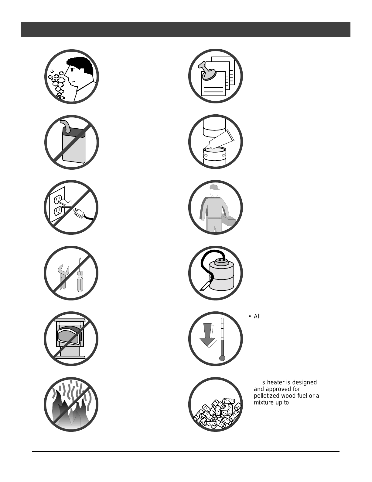
Gas
• Do not operate the
heater if you smell
smoke coming from
the heater. Turn the
MODE switch to
"OFF", monitor your
heater, and call your
dealer.
• Never use gasoline,
gasoline-type lantern fuel,
kerosene, charcoal lighter
fluid, or similar liquids to
start or 'freshen up' a fire in
this heater. Keep all such
liquids well away from the
heater while it is in use.
• Do not unplug the heater
if you suspect a
malfunction. Turn the
MODE SWITCH to "OFF"
and periodically inspect
the heater.
Ok
Sealant
• Contact your local building
officials to obtain a permit
and information on any
installation restrictions or
inspection requirements
in your area. Notify your
insurance company of this
heater as well.
• The exhaust system must
be completely airtight and
properly installed. The
pellet vent joints must be
sealed with RTV 500o F.
(260o C.) silicone sealant.
• This unit must be properly
installed to prevent the
possibility of a house fire.
The instructions must be
strictly adhered to. Do not
use makeshift methods or
compromise in the
installation.
• Never try to repair or
replace any part of the
heater unless instructions
are given in this manual.
All other work should be
done by a trained
technician.
• The viewing door and
ashpan must be closed
and latched during
operation.
• Never block free airflow
through the open vents of
the unit.
• Do not operate the heater
if the flame becomes dark
& sooty of if the firepot
overfills with pellets. Turn
the MODE SWITCH to
"OFF" and periodically
inspect the heater (see
"Running Your Heater").
• Your heater requires
periodic maintenance and
cleaning (see "Maintaining
Your Heater"). Failure to
maintain your heater may
lead to smoke spillage in
your home.
• Allow the heater to cool
before carrying out any
maintenance or cleaning.
Ashes must be disposed
in a metal container with a
tight lid and placed on a
non-combustible surface
well away from the home
or structure.
• This heater is designed
and approved for
pelletized wood fuel or a
mixture up to 50% corn,
50% pellets. See page 25
for details on using a corn
pellet mix.
© Travis Industries 4080728 100-01156

Safety Precautions 5
• The heater will not operate
during a power outage. If
a power outage does
occur, check the heater
for smoke spillage and
open a window if any
smoke spills into the room.
• Keep foreign objects out
?
of the hopper.
Mobile
Home
• Disconnect the power
cord before performing
any maintenance.
NOTE:
Turning the Mode Switch
to "OFF" does not
disconnect all power to
the heater.
• This heater must be
connected to a standard
115 V., 60 Hz grounded
electrical outlet. Do not
use an adapter plug or
sever the grounding plug.
Do not route the electrical
cord underneath, in front
of, or over the heater.
• When installed in a mobile
home, the heater must be
bolted to the floor, have
outside air, and NOT BE
INSTALLED IN THE
BEDROOM (Per H.U.D.
requirements). Check
with local building officials.
• The exhaust system
should be checked twice a
year minimum for any
build-up of soot or
creosote.
This
Manual
• Do not throw this manual
away. This manual has
important operating and
maintenance instructions
that you will need at a later
time. Always follow the
instructions in this manual.
• Do not place clothing or
other flammable items on
or near the heater.
Because this heater can
be controlled by a
thermostat there is a
possibility of the heater
turning on and igniting any
items placed on or near it.
• Do not touch the hot
surfaces of the heater.
Educate all children of the
danger of a hightemperature heater.
Young children should be
supervised when they are
in the same room as the
heater.
• Travis Industries, Inc.
grants no warranty,
implied or stated, for
the installation or
maintenance of your
heater, and assumes
no responsibility of
any consequential
damage(s).
© Travis Industries 4080728 100-01156
6 Specifications
Heating Specifications
Approximate Maximum Heating Capacity (in square feet)* ........................................800 to 2,250 Sq. Feet
Burn Rate (Pounds per Hour)**............................................................................1.7 to 5.5
Maximum Burn Time on Low Burn** ......................................................................47 Hours
Hopper Capacity ..............................................................................................80 Pounds
* Heating capacity will vary depending on the home's floor plan, degree of insulation, and the outside temperature. It is also affected
by the fuel size, quality, and moisture level.
** Small pellets will increase or decrease the stated burn rates and burn times. Differences of plus or minus 20% depending on fuel
quality may occur.
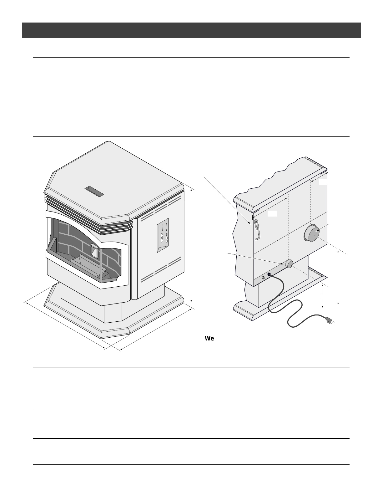
Dimensions
This tab can be bent
out and used to hang
the scraper rod tool.
32"
Air Inlet
(1-3/4"
Outside
Diameter)
5-1/4"
13"
4"
Diameter
Exhaust
9-1/4"
25"
23"
Weight: 225 Lbs.
Electrical Specifications
Electrical Rating.........................................................................................115 Volts, 3.6 Amps, 60 Hz
Watts During Start-Up Sequence...................................................................400 (approximately)
Watts During Operation ...............................................................................180 (approximately)
Fuel
• This heater is designed and approved for pelletized wood fuel or a mixture up to 50% corn, 50% pellets.
See page 25 for details on using a corn pellet mix.
EPA Compliance
This heater has been tested exempt from EPA Phase II Requirements by OMNI-Test Laboratories, Inc.
16-1/2"
© Travis Industries 4080728 100-01156

Installation (For Qualified Installers Only) 7
Before You Begin
READ THIS ENTIRE MANUAL BEFORE YOU INSTALL AND USE THIS HEATER.
FAILURE TO FOLLOW THE INSTRUCTIONS MAY RESULT IN PROPERTY DAMAGE,
BODILY INJURY, OR EVEN DEATH.
Check with local building officials for any permits required for installation of this pellet heater and notify
your insurance company before proceeding with installation.
Packing List
• Thermostat & Wire • Scraper Rod Tool • Brush • Spare Fuses
Installation Options
• Residential or Mobile Home (see the section "Mobile Home Requirements")
• Alcove Compatible (see the section "Alcove Installation")
• Horizontal or Vertical Vent
• Outside Air Compatible
• Vent with L-Vent, L-Vent Fireplace Liner, or Type A Chimney (with adapter)
Planning The Installation
HINT: Have an authorized Travis Industries dealer install this heater. If you install the heater
yourself, have your dealer review your installation plans.
HINT: Sketch out a detailed plan of the installation including dimensions. Then verify the
dimensions with the requirements listed in this manual.
HINT: When determining the location of the stove, locate the wall studs (for horizontal
penetrations) and ceiling trusses (for vertical penetrations). You may wish to adjust the
stove position slightly to ensure the vent does not intersect with a framing member.
HINT: Place the heater outside and load 10 pounds of pellets inside the hopper. Plug the
heater in and let it run on HIGH until the pellets run out. This will cure the paint and burn
off any oil on the steel, eliminating any smell inside the home.
Stove Placement
• Stove must be placed so that no combustibles are within, or can swing within (e.g. drapes,
doors), 36" of the front of the heater.
• If the stove is placed in a location where the ceiling height is less than 7', it must follow the
requirements in the section "Alcove Installation Requirements".
HINT: REDUCING CLEARANCES - Clearances may be reduced by methods specified in NFPA
211, listed wall shields, pipe shields, or other means approved by local building or fire
officials.
• Heater and floor protection must be installed on a level, secure floor.
Floor Protection Requirements
• The heater must be installed on a non-combustible floor protector extending the full width
and depth of the heater and extending 6" in front (minimum 27-3/4" wide by 31" deep)
(minimum .018" thick - 26 gauge) .
• Must extend under and 2" to each side and rear of a "Tee" (if used).
© Travis Industries 4080728 100-01156
8 Installation (For Qualified Installers Only)
A
A
A
A
A
A
A
A
A
A
A
A
A
A
A
A
A
A
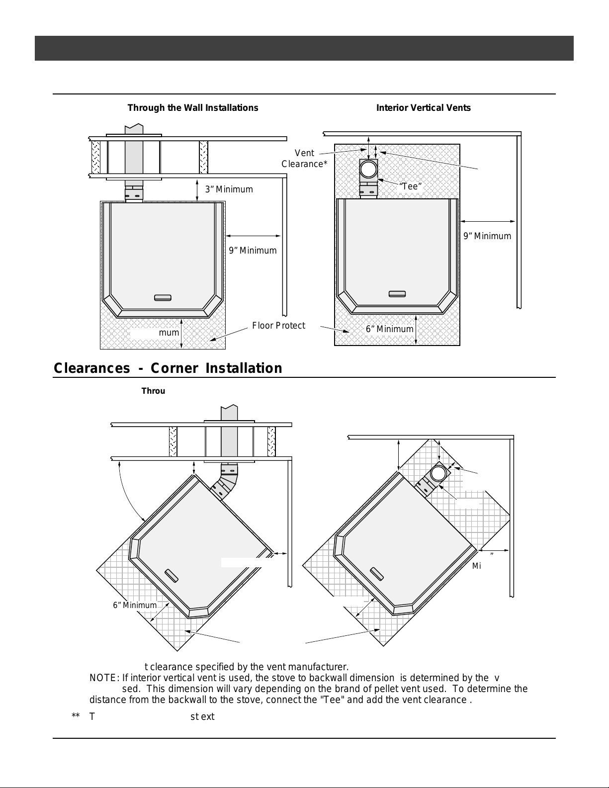
Clearances - Straight Installation
Through the Wall Installations Interior Vertical Vents
Vent
Clearance*
3” Minimum
AAAAAA
AAAAAA
“Tee”
AAAAAA
2”
Minimum**
AAAAAA
AAAAAA
AAAAAA
9” Minimum
AAAAAA
AAAAAA
AAAAAA
AAAAAA
6” Minimum
Floor Protection
AAAAAA
Clearances - Corner Installation
Through the Wall Vents
3” Minimum
45°
45° Elbow
AAAAAA
AAAAAA
AAAAAA
AAAAAA
AAAAAA
AAAAAA
AAAAAA
6” Minimum
Interior Vertical Vents
3”
Minimum
9” Minimum
Vent Clearance*
2”
Minimum**
“Tee”
3”
Minimum
6” Minimum
3” Minimum
6” Minimum
* Install vent at clearance specified by the vent manufacturer.
** The floor protection must extend 2” or to the wall (whichever is less) – all vent clearances must be met.
© Travis Industries 4080728 100-01156
NOTE: If interior vertical vent is used, the stove to backwall dimension is determined by the vent
being used. This dimension will vary depending on the brand of pellet vent used. To determine the
distance from the backwall to the stove, connect the "Tee" and add the vent clearance .
Floor Protection
Installation (For Qualified Installers Only) 9
Venting the Pellet Stove
• INSTALL VENT AT CLEARANCES SPECIFIED BY THE VENT
MANUFACTURER.
• DO NOT CONNECT THE PELLET VENT TO A VENT SERVING ANY
OTHER APPLIANCE OR STOVE.
• DO NOT INSTALL A FLUE DAMPER IN THE EXHAUST VENTING SYSTEM
OF THIS UNIT.
• USE AN APPROVED WALL THIMBLE WHEN PASSING THE VENT
THROUGH WALLS AND A CEILING SUPPORT/FIRE STOP SPACER
WHEN PASSING THE VENT THROUGH CEILINGS (MAKE SURE TO
MAINTAIN CLEARANCE TO ANY COMBUSTIBLES).
• No more than one tee and 180° of elbows (one tee with two 90° elbows, one tee with one
90° and two 45° elbows, etc.).
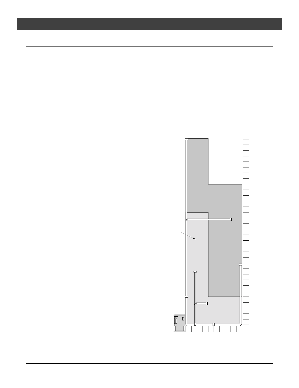
33 Feet
(max.)
Maximum Venting
Distance
• Vent must have a support
bracket every 5' of pellet vent
when exterior of structure
The vent height and run
must not exceed the
distance shown in the
shaded region shown to the
right.
Venting into this shaded
area may require restrictor
adjustments. See the
section “Restrictor
Adjustment” for details.
NOTE: To achieve optimum
performance, we
recommend keeping the
vent as short as possible
(horizontal run especially).
30 Feet
25 Feet
20 Feet
15 Feet
10 Feet
5 Feet
0 Feet
10 Feet
0 Feet
5 Feet
(max.)
© Travis Industries 4080728 100-01156
10 Installation (For Qualified Installers Only)
Pellet Vent Type
• Must be 4" diameter Type "L" (except for masonry fireplace installations) - or - connect the
vent to a factory built type "A" chimney. All vent joints (including adapters, elbows, etc…)
must be sealed with 500° F. RTV silicone.
Installing the Pellet Vent
Seal each vent section (including
adapters, elbows, etc...) by
500° F. RTV
Silicone
• Horizontal sections must have a 1/4" rise every 12" of travel.
• Pellet vent connections must be sealed airtight with 500° F. RTV silicone and screwed
together with at least three sheet metal screws.
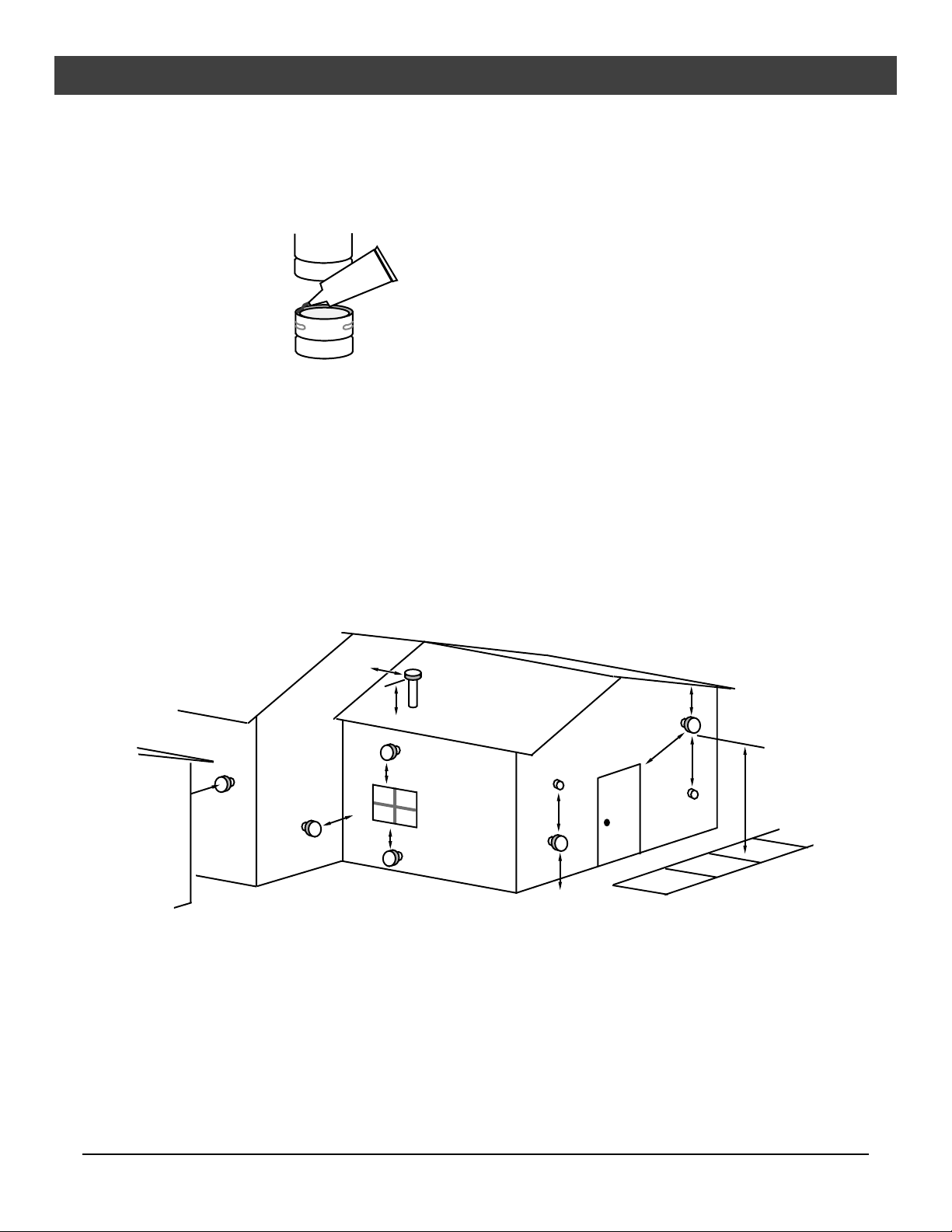
Pellet Vent Termination
• Vent must terminate on the exterior of the dwelling. Horizontal terminations must protrude a
minimum12" from the wall. Vertical terminations must protrude a minimum 24" from the roof
surface. In addition, all clearances listed below must be met.
• Must have an approved cap (to prevent water from entering) or a 45° downturn with rodent screen.
• If the termination is located on a windy side of the house, an approved house shield is
recommended to prevent soot from building up on the side of the house.
• Must not be located where it will become plugged by snow or other material.
injecting a liberal amount of 500°
F. RTV silicone into the gap
between sections.
H
X
A
B
C
NOTE: Measure clearances to the nearest edge of the exhaust hood.
A Minimum 4' clearance below or beside any door or window that opens
(This clearance may be reduced to18” if using outside air (see page 11) – we recommend
the door or window be kept closed during operation.
Minimum 1’ clearance below or beside any window that does not open.
B Minimum 1' clearance above any door or window that opens
C Minimum 2' clearance from any adjacent building
D Minimum 7' clearance above any grade when adjacent to public walkways
NOTE: Vent may not terminate in covered walkway or breezeway.
E Minimum 2' clearance above any grass, plants, or other combustible materials
F Minimum 3' clearance from any forced air intake of any other appliance
G Minimum 2' clearance below eaves or overhangs
H Minimum 1' clearance horizontally from combustible wall
X Must be a minimum of 2' above the roof
H
A
F
E
G
F
D
© Travis Industries 4080728 100-01156
Installation (For Qualified Installers Only) 11
AA
AA
AA
AA
AAA
AAA
A
A
Mobile Home Requirements
• Outside air is required (used for
combustion) - see the directions
below.
• The heater must be bolted to the
floor (Some states do not require
this; check with your local building
department). See the illustration
to the right.
• The heater must be grounded to
the steel chassis of the mobile
home (Some states do not require
this; check with your local building
department).
WARNING: DO NOT INSTALL IN
SLEEPING ROOM.
CAUTION: THE STRUCTURAL
INTEGRITY OF THE
MANUFACTURED HOME
FLOOR, WALL, AND
CEILING/ROOF MUST BE
MAINTAINED.
b
Use the lag bolts (used
to secure the stove to
the pallet) to screw the
pedestal to the floor.
7/16”
Socket
a
Remove the ash pan
(see page 29).
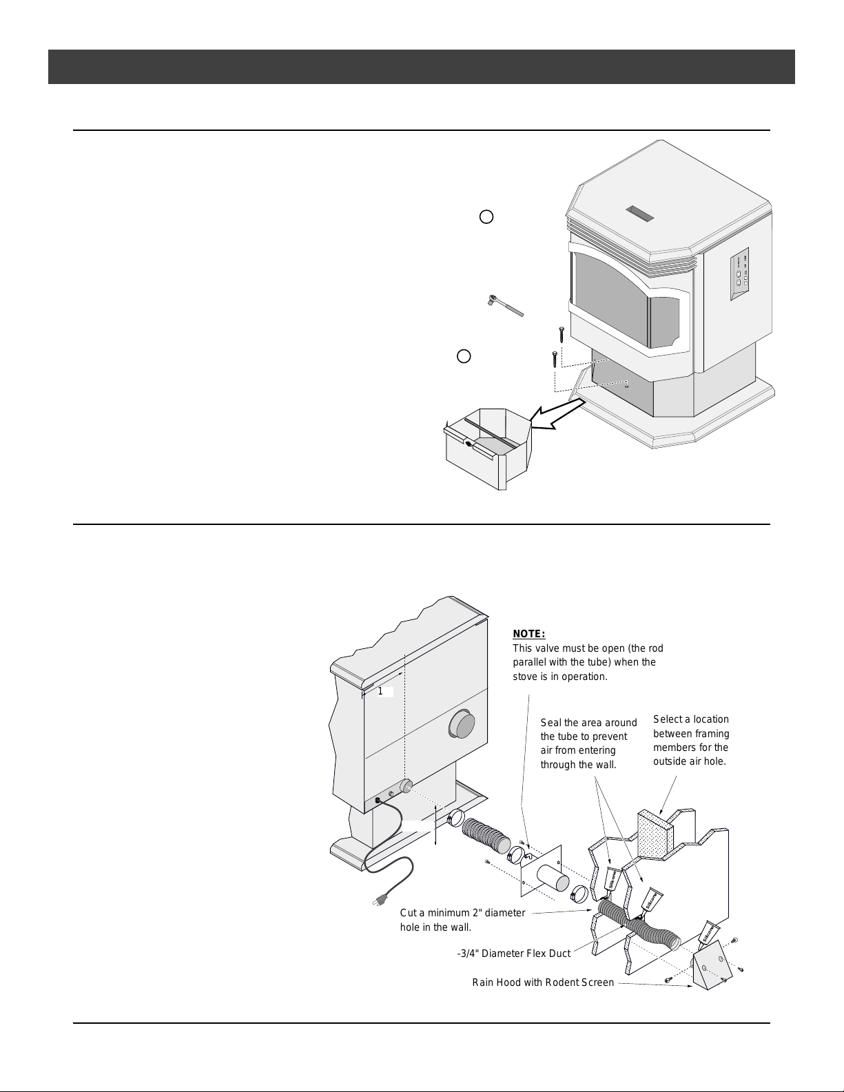
Outside Air (used for combustion)
• Must not be drawn from an enclosed space (garage, unventilated crawl space).
HINT: Travis Industries strongly suggests outside air for all residential installations, especially for
those that are energy efficient, air-tight homes.
• Must not be over 15' long.
• Must be made with 1 3/4"
diameter or larger metal or
aluminum duct with a metal
screen attached to the end
to keep out rodents
(P.V.C. or other
combustible materials may
not be used). We
recommend the Travis
Industries Outside Air Kit
(part # 99200136).
• Must not terminate above
or within 1' of the chimney
termination.
• Must have a rain cap or
down-turned elbow to
prevent water from
entering.
• Must be located so that it
will not become plugged by
snow or other material.
13"
NOTE:
This valve must be open (the rod
parallel with the tube) when the
stove is in operation.
9-1/4"
Cut a minimum 2" diameter
hole in the wall.
1-3/4" Diameter Flex Duct
Seal the area around
the tube to prevent
air from entering
through the wall.
Silicone
Select a location
between framing
members for the
outside air hole.
Silicone
Silicone
Rain Hood with Rodent Screen
© Travis Industries 4080728 100-01156
12 Installation (For Qualified Installers Only)
Alcove Installation Requirements
When the pellet stove is placed in a location where the ceiling height is less than 7' tall, it is considered
an alcove installation. Because of the reduced height, the requirements listed below must be met.
• Minimum height is 60"
• Minimum width is 43"
Baffle Installation
Install the baffles included with the stove (see page 29 for details).
Door Seal Verification
The door is aligned prior to leaving the factory. However, shipping and installation may cause the door to
become mis-aligned. Verify the door is correctly aligned and seals properly (see the section "Door Seal"
under Yearly Maintenance).
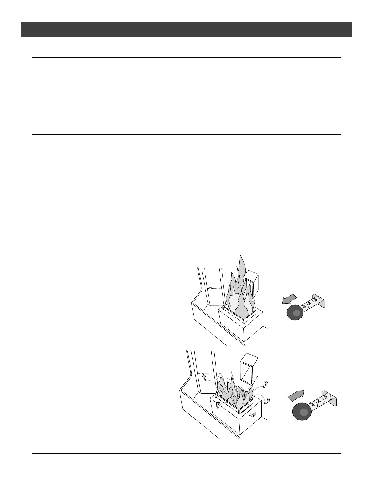
Restrictor Adjustment
The restrictor is used to adjust airflow to the firepot. It should be adjusted to match the heat output setting
and burn the pellets at the appropriate rate. This keeps the firepot as clean as possible.
For low heat output settings the restrictor will need to be closed or near closed to limit the amount of air.
This prevents the stove from burning the pellet fuel faster than it is fed.
For medium heat output settings the restrictor will need to be opened to a medium position.
For high heat output settings the restrictor will need to be opened to a high position. This prevents the
firepot from over-filling with pellets and becoming clogged with ash clumps.
Keeping your firepot clean is the most important step to maintaining a safe and efficient stove. Check and
clean your firepot daily until you find the correct restrictor settings and appropriate firepot cleaning interval.
• Maximum depth is 48"
• Minimum clearance of 9" on each side and 3" on back
Not Enough Air
If clinkers (ashes that solidify into a clump)
develop or the flame appears lazy and slow
to blow the ash out of the firepot, pull the
restrictor outward until the flame becomes
active and the firepot holes remain clean.
NOTE: If the restrictor is fully out, yet the
firepot does not remain clean, the stove
needs to be cleaned and checked for air
leaks (see “Maintenance” section of this
manual).
Too Much Air
If the flames are too active (small, flickering
flames) or if burning pellets are expelled
from the firepot, move the restrictor rod
inwards until the flame slows down and no
burning pellets are expelled (note: it is okay
to have “glowing embers” jump out of the
firepot). Another symptom of too much air
is the heater “blowing the fire out” – a
condition in which the pellets burn faster
than they are fed (this is most common on
low).
© Travis Industries 4080728 100-01156

Installation (For Qualified Installers Only) 13
Thermostat Installation
! Do not connect 120 VAC to the thermostat circuit of this heater (do not use a
household thermostat used for a wall-board or other electical heater).
A thermostat is included with this heater (part # 99300650). Follow the directions below to install.
1 Attach the thermostat
wire to the circuit board
(see the illustration
below). Route the wire
through the back of the
heater (away from any hot
or moving components).
50 60 70 80 90
Pull the cover off the thermostat
Attach the quick-connects
to the two posts near the
molex connector on the
circuit board (orientation
does not mater).
2 Determine a location for
the thermostat that is
within range of the 20'
length of thermostat wire.
It should be centralized in
the room and away from
the heater. The wire may
be routed externally on
the wall or behind the wall
(preferred).
Robertshaw
50 60 70 80 90
Run the thermostat wires
through the wall (cut off excess
wire, leaving 6” of slack).
Expose 1/2” of wire and
attach to these two posts.
Standard
Screwdriver
3 Follow the directions to
the right to attach the
thermostat and
thermostat wires.
Attach the thermostat to
the wall through these
two holes.
© Travis Industries 4080728 100-01156
 Loading...