


1750 Wood Stove
Owner's Manual
• |
Freestanding Stove |
• |
Alcove Approved |
• |
Mobile-Home Approved |
• |
Hearth-Stove Approved |
|
|
|
|
Save these instructions for future reference
SAFETY NOTICE:
If this appliance is not properly installed, a house fire may result. For your safety, follow the installation directions. Contact local building or fire officials about restrictions and installation inspection requirements in your area.
Travis Industries, Inc. |
|
Copyright 2007, T.I. |
|
||
4800 Harbour Pointe Blvd. SW |
Listed |
||||
$10.00 |
100-01179 |
||||
Mukilteo, WA 98275 |
|||||
|
|
||||
|
|
4060802 |
Tested to: U.L. 1482 |
||
|
|
|
|
||
Test Report # 028–S–62b-4
2 |
Introduction |
Introduction
We welcome you as a new owner of a 1750 wood-burning stove. In purchasing a 1750 you have joined the growing ranks of concerned individuals whose selection of an energy system reflects both a concern for the environment and aesthetics. The 1750 is one of the finest appliances the world over. This manual will explain the installation, operation, and maintenance of this appliance. Please familiarize yourself with the Owner's Manual before operating your appliance and save the manual for future reference. Included are helpful hints and suggestions which will make the installation and operation of your new appliance an easier and more enjoyable experience. We offer our continual support and guidance to help you achieve the maximum benefit and enjoyment from your appliance.
Important Information
No other 1750 appliance has the same serial number as yours. The serial number is stamped onto the label on the back of the appliance.
This serial number will be needed in case you require service of any type.
Model: 1750
Serial Number:
Purchase Date:
Purchased From:
Register your warranty online at:
traviswarranty.com
Or, mail your warranty card to:
Travis Industries House of Fire
4800 Harbour Pointe Blvd. SW
Mukilteo, WA 98275
Save Your Bill of Sale.
To receive full warranty coverage, you will need to show evidence of the date you purchased your heater. Do not mail your Bill of Sale to us.
We suggest that you attach your Bill of Sale to this page so that you will have all the information you need in one place should the need for service or information occur.
|
|
|
|
|
|
|
|
|
|
|
|
|
|
|
|
|
|
|
|
|
|
|
|
|
|
|
|
|
|
|
|
|
|
|
|
|
|
|
|
|
|
|
|
|
|
|
|
|
|
|
|
|
|
|
|
|
|
|
|
|
|
|
|
|
|
|
|
|
|
|
|
|
|
|
|
|
|
|
|
|
|
|
|
|
|
|
|
|
|
|
|
|
|
|
|
|
|
|
|
|
|
|
|
|
|
|
|
|
|
|
|
|
|
|
|
|
|
|
|
|
|
|
|
|
|
|
|
|
|
|
|
|
|
|
|
|
|
|
|
|
|
|
|
|
|
|
|
|
|
|
|
|
|
|
|
|
|
|
|
|
|
|
|
|
|
|
|
|
|
|
|
|
|
|
|
|
|
|
|
|
|
|
|
|
|
|
|
|
|
|
|
|
|
|
|
|
|
|
|
|
|
|
|
|
|
|
|
|
|
|
|
|
|
|
|
|
|
|
|
|
|
|
|
|
|
|
|
|
|
|
|
|
|
|
|
|
|
|
|
|
|
|
|
|
|
|
|
|
|
|
|
|
|
|
|
|
|
|
|
|
|
|
|
|
|
|
|
|
|
|
|
|
|
|
|
|
|
|
|
|
|
|
|
|
|
|
|
|
|
|
|
|
|
|
|
|
|
|
© Travis Industries |
100-01179 |
|
|
4060926 |
||||||||||||||||||

Table of Contents |
3 |
General Information |
|
Introduction & Important Information...................... |
2 |
Safety Precautions ............................................ |
4 |
Features & Specifications.................................... |
6 |
Stove Installation |
|
Planning the Installation...................................... |
7 |
Preparation for Installation .............................. |
7 |
Stove Installation Considerations ..................... |
7 |
Floor Protection Requirements ............................. |
8 |
Stove Placement Requirements ........................... |
8 |
Clearances ...................................................... |
8 |
Top View - Straight Installation ........................ |
9 |
Top View - Corner Installation ......................... |
9 |
Chimney Connector Requirments ......................... |
10 |
Chimney Requirements ...................................... |
11 |
Chimney Termination Requirements...................... |
12 |
Outside Air Requirements ................................... |
12 |
Alcove Installation Requirements .......................... |
13 |
Mobile Home Requirements ................................ |
14 |
INSTALLATION DIAGRAMS |
|
Standard Ceiling with a Factory Built Chimney .... |
15 |
Cathedral Ceiling with a Factory Built Chimney ... |
15 |
Hearth Stove Positive Connection .................... |
16 |
Hearth Stove Direct Connection....................... |
17 |
Interior or Exterior Masonry Chimney ................ |
17 |
Operating Your Appliance |
|
Safety Notice.................................................... |
18 |
Operating the Stove when it is Hot ................... |
|
Before Your First Fire ......................................... |
18 |
Curing the Paint ........................................... |
18 |
Over-Firing the Stove .................................... |
18 |
Opening the Doors ............................................ |
19 |
Starting a Fire................................................... |
20 |
Adjusting the Burn Rate ...................................... |
21 |
Approximate Air Control Settings ..................... |
21 |
Operating Your Appliance (continued) |
|
Ash Removal.................................................... |
21 |
Blower Operation .............................................. |
22 |
Re-Loading the Stove......................................... |
22 |
Overnight Burn ................................................. |
22 |
Normal Operating Sounds ................................... |
22 |
Hints for Burning ............................................... |
23 |
Selecting Wood................................................. |
23 |
Why Dry Wood is Key.................................... |
23 |
Wood Cutting and Storage.............................. |
23 |
Troubleshooting ................................................ |
24 |
Maintaining Your Appliance |
|
Daily Maintenance (while stove is in use) ............... |
25 |
Remove Ash (if necessary) ............................. |
25 |
Clean the Glass (if necessary)......................... |
25 |
Monthly Maintenance (while appliance is in use) ...... |
26 |
Door and Glass Inspection.............................. |
26 |
Creosote - Formation and Need for Removal...... |
26 |
Yearly Maintenance ........................................... |
27 |
Touch Up Paint ............................................ |
27 |
Cleaning the Air Duct and Blower (if applicable) .. |
27 |
Door Parts ....................................................... |
28 |
Replacing the Glass ...................................... |
28 |
Replacing the Door Gasket ............................. |
28 |
Replacing the Door Handle ............................. |
28 |
Firebox Parts.................................................... |
29 |
Brick Removal & Replacement ........................ |
|
Combustor Removal & Replacement ................ |
|
Warranty |
|
Warranty ......................................................... |
34 |
Listing Information |
|
Listing Information ............................................. |
33 |
Optional Equipment |
|
Stove Leg Installation ......................................... |
34 |
Pedestal Installation........................................... |
34 |
Outside Air Connector ........................................ |
34 |
Rear Blower Installation ...................................... |
35 |
Index |
|
Index .............................................................. |
36 |
© Travis Industries |
100-01179 |
4060926 |
4 |
Safety Precautions |
The viewing door must be closed and latched during operation.
Never block free airflow through the air vents on this appliance.
This appliance is designed and approved for the burning of cord wood only. Do not attempt to burn any other type of fuel other than cord wood in this appliance, it will void all warranties and safety listings.
Do not touch the appliance while it is hot and educate all children of the danger of a hightemperature appliance. Young children should be supervised when they are in the same room as the appliance.
This appliance must be properly installed to prevent the possibility of a house fire. The instructions must be strictly adhered to. Do not use makeshift methods or compromise in the installation.
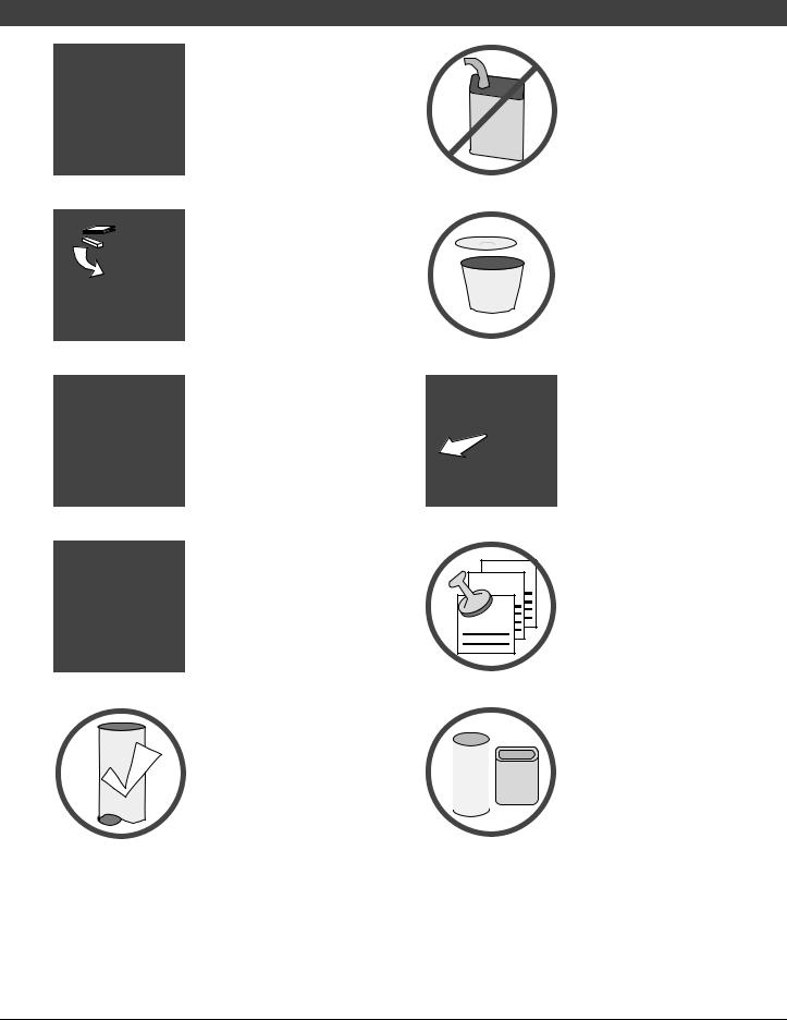
ASHES
36"
Ok
Gasoline or other flammable liquids must never be used to start the fire or "Freshen Up" the fire. Do not store or use gasoline or other flammable liquids in the vicinity of this appliance.
Ashes must be disposed in a metal container with a tight lid and placed on a noncombustible surface well away from the home or structure.
Keep furniture, drapes, curtains, wood, paper, and other combustibles a minimum of 36" away from the front of the appliance.
Contact your local building officials to obtain a permit and information on any installation restrictions or inspection requirements in your area. Notify your insurance company of this appliance as well.
Inspect the chimney connector and chimney at least twice monthly and clean if necessary. Creosote may build up and cause a house fire.
Do not connect this appliance to any chimney serving another appliance.
|
|
This appliance must be |
|
|
|
Type |
|
connected to a listed high |
Clay |
temperature (UL 103 HT) |
|
HT |
Liner |
residential type chimney or an |
|
|
approved masonry chimney with |
|
|
a standard clay tile, or stainless |
|
|
steel liner. |
© Travis Industries |
100-01179 |
4060926 |
|
Safety Precautions |
|
When installed in a mobile |
|
home, this appliance must be |
|
bolted to the floor, have outside |
Mobile |
air, and not be installed in the |
bedroom (Per H.U.D. |
|
Home |
requirements). Check with local |
|
building officials. |
Never try to repair or replace any part of this appliance unless instructions are given in this manual. All other work must be done by a trained technician.
Allow the appliance to cool before carrying out any maintenance or cleaning.
Maintain the door and glass seal and keep them in good condition.
Avoid placing wood against the glass when loading. Do not slam the door or strike the glass.
Do not throw this manual away. This manual has important operating and maintenance instructions that you will need at a later time. Always follow the instructions in this manual.
5
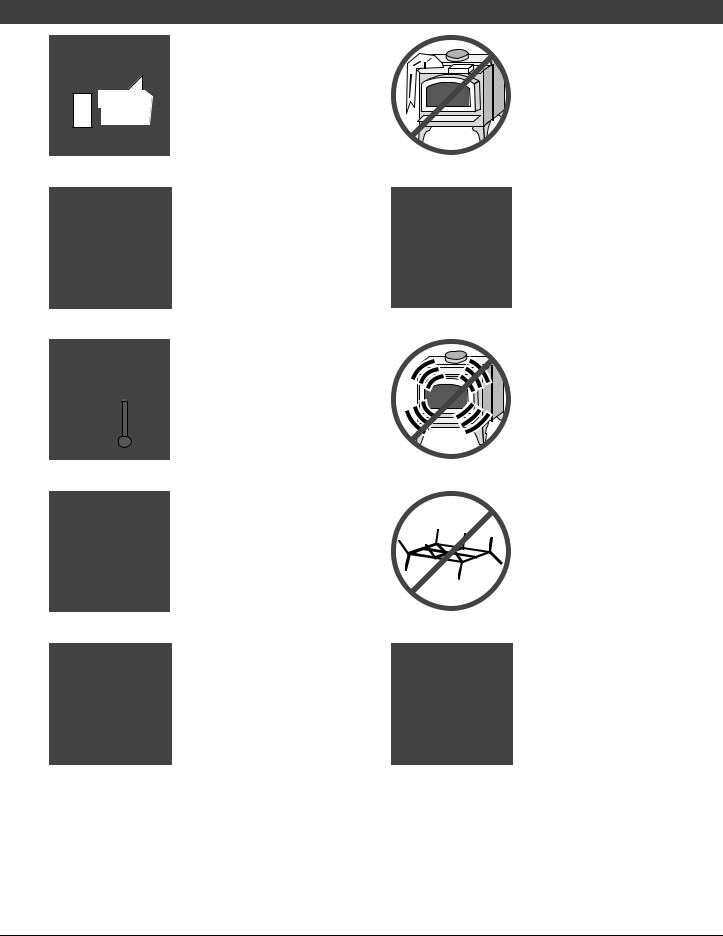
Do not place clothing or other flammable items on or near this appliance.
Do not make any changes or modifications to an existing masonry fireplace or chimney to install this appliance.
Do not make any changes to the appliance to increase combustion air
Overfiring the appliance may cause a house fire. If a unit or chimney connector glows, you are overfiring.
Do not use a grate or other device to elevate the fire off of the firebox floor. Burn the fire directly on the bricks.
Travis Industries, Inc. grants no warranty, implied or stated, for the installation or maintenance of your appliance, and assumes no responsibility of any consequential damage(s).
© Travis Industries |
100-01179 |
4060926 |
6 |
Features & Specifications |
Installation Options
•Freestanding
•Freestanding in an Alcove
•Freestanding in a Mobile Home
•Freestanding Hearth Stove
Features
•EPA Phase II Approved
•2.2 Cubic Foot Firebox Volume
•Single Operating Control
•Accepts Logs Up to 18” Long
•Steel Plate Construction (5/16" & 3/16")
•Heavy Duty Refractory Firebrick
•Optional High-Tech Blower
Heating Specifications
Approximate Maximum Heating Capacity (in square feet)* |
1,200 to 2,000 |
Maximum BTU's per Hour (Cord Wood Calculation) |
72,400 |
Overall Efficiency (Oregon Method) |
70.4 % |
Maximum Burn Time |
Up to 10 Hours |
* Heating capacity will vary depending on the home's floor plan, degree of insulation, and the outside temperature. It is also affected by the quality and moisture level of the fuel.
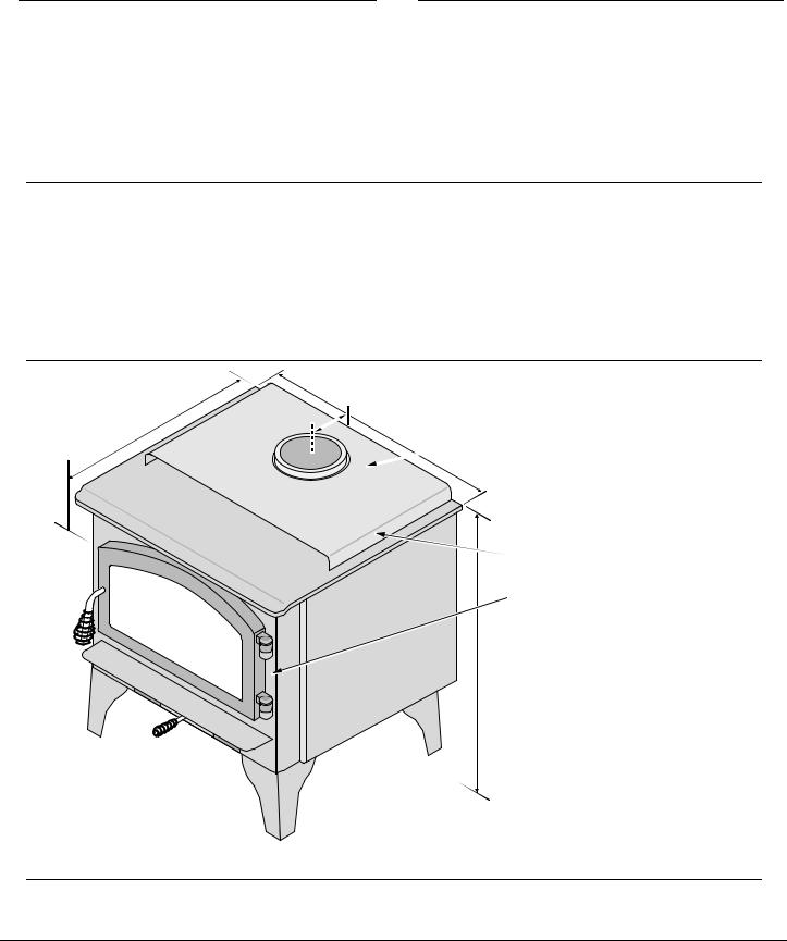
Dimensions
23-1/2”
5-3/4” |
24” |
The 6” diameter flue collar protrudes |
|
|
2-1/4" above the stove top
Note:
Measure side, corner, and back clearances from the stove top. Measure front clearances from the stove face.
Height: |
|
Sculptured or Cast Legs..... |
26-1/2" |
Lopi Pedestal...................... |
30-5/8" |
Avalon Pedestal.................. |
30-1/2” |
Weight: 430 Lbs.
Figure 1
Emissions
1.9 Grams Per Hour (EPA Phase II Approved) – Tests conducted by E.E.S.P.C.
© Travis Industries |
100-01179 |
4060926 |
Stove Installation (for qualified installers only) |
7 |
SAFETY NOTICE:
Please read this entire manual before you install and use yournew roomheater. Failure to follow instructions may result in property damage, bodily injury, oreven death. Contact local building orfire officials about restrictions and installation inspection requirements in yourarea.
Always use gloves when operating a hot stove. The door handle and other components become very hot during normal use.
Planning The Installation
We suggest that you have an authorized Travis Industries dealer install your stove. If you install the stove yourself, your authorized dealer should review your installation plans.
Check with local building officials for any permits required for installation of this stove and notify your insurance company before proceeding with installation.
Preparation for Installation
The stove can be lightened by removing the firebricks and baffle (pg 29) - replace before operation.
•Check for damage to the exterior of the stove.
•Check the interior of the firebox (replace cracked firebrick and make sure baffle is in place).
•The door (shipped separately - SKU 96100612 or 96100724) must be installed prior to operation.
•The stove must be placed on legs (see page 34) or a pedestal (see page 34).
Stove Installation Considerations
The table below details the six most common types of installations and the considerations for each type. Alternative methods of installation are available if they comply with local building codes.
Installation Type |
Considerations |
|
|
|
|
Standard Ceiling with a Factory Built Chimney |
• |
Requires ceiling and roof penetration |
(Page 15) |
• |
Provides best draft |
|
|
|
Cathedral Ceiling with a Factory Built Chimney |
• |
Cathedral style chimney support required |
(Page 15) |
• |
Provides best draft |
|
|
|
Hearth Stove Positive Connection |
• |
Utilizes existing masonry fireplace (not approved for zero |
(Page 16) |
• |
clearance (metal) fireplaces) |
|
Provides good draft due to full reline |
|
|
• |
Easier to clean than direct or horizontal hearth stove |
Hearth Stove Direct Connection |
• |
Utilizes existing masonry fireplace (not approved for zero |
(Page 17) |
• |
clearance (metal) fireplaces) |
|
Requires construction of a "block-off plate" |
|
|
• |
Draft reduced due to elbows & chimney cross section |
Interior Masonry Chimney |
• |
Utilizes existing masonry chimney (not approved for zero |
(Page 17) |
|
clearance (metal) fireplaces) |
|
|
|
© Travis Industries |
100-01179 |
4060926 |

8 |
Stove Installation (for qualified installers only) |
Floor Protection Requirements
•Stove must be placed on the Travis Industries legs or Pedestal.
•Floor protection must extend 6" to the sides and rear of the stove and 16" to the front of the stove (36" wide by 45-1/2" deep - see Figure 2 and Figure 3). NOTE: when installed with reducedclearance connector, the clearance to the backwall is less than 6". In this case the floor protection must extend to the wall.
•Floor protection must be non-combustible and at least .018" thick (26 guage).
Stove Placement Requirements
Clearances may be reduced by methods specified in NFPA 211, listed wall shields, pipe shields, or other means approved by local building or fire officials.
•Stove must be placed so that no combustibles are within, or can swing within (e.g. drapes, doors), 36" of the front of the stove
•If the stove is placed in a location where the ceiling height is less than 7', it must follow the requirements in the section "Alcove Installation Requirements"
•Must maintain the clearances to combustibles listed below (drywall, furniture, etc.):
Clearances
• The following clearances must be met (see Figure 2 and Figure 3)
Minimum Clearance |
Singlewall |
Reduced |
|
|
|
Connector |
Clearance* |
|
|
|
|
A |
Sidewall to stove |
15" |
13" |
B |
Backwall to stove |
15” |
4-1/4" |
C |
Cornerwall to stove |
15" |
6-1/2" |
D |
Connector to sidewall |
24" |
21-1/2" |
E |
Connector to backwall |
17-3/4" |
6-1/2" |
F |
Connector to cornerwall |
24" |
15" |
|
|
|
|
*Reduced clearance installations require one of the chimneys and connectors listed below:
AMERI-TEC model DCC with model HS chimney
DURAVENT model DVL with DURATEC or DURA-PLUS chimney
GSW Super Chimney Twenty-One connected directly to appliance
I.C.C. Excel (2100-2 Can.) (103-HT USA) chimney with HP connector
METALFAB model DW connector with TG chimney
OLIVER MACLEOD PROVENT model PV connector with model 3103 chimney
SECURITY model DP connector with SECURITY model ASHT or S2100 chimney
SELKIRK METALBESTOS model DS connector with model SSII chimney
Standard Masonry Chimney with any one of the above listed connectors
NOTE: Reduced clearance connectors may not connect to the flue collar – an appliance adapter may be required.
NOTE: Mobile Home installations must use the reduced clearance connector and clearances listed above.
NOTE: Standard residential installations with reduced clearance connector may use the
“Connector to Wall” clearance determined by the connector manufacturer if approved by local code. This clearance is established by the connector manufacturer and falls under the connector manufacturer’s listing. “Stove to Wall” clearances must always be met.
© Travis Industries |
100-01179 |
4060926 |

Stove Installation (for qualified installers only) |
9 |
Top View -
Straight Installation
Back Wall |
|
|
Clearance B |
Wall |
|
Clearance E |
|
|
|
6” Min. |
Side |
24” |
|
|
|
|
|
|
Clearance A |
|
5-3/4” |
6” Min. |
|
|
Clearance D |
|
23-1/2”
Measure rear and side clearances from the nearest edge of the stove top.
NOTE: vent diameter may vary depending on brand and model.
Measure front clearances
16” Min.
from the face of the stove (unibody).
Floor Protection
Figure 2
Top View -
Corner Installation
Corner |
Wall |
|
Clearance F
Corner
Wall
Clearance C
|
|
6” Min. |
|
|
24” |
|
5-3/4” |
6” Min. |
|
23-1/2” |
Measure rear and side |
|
|
|
|
|
clearances from the nearest |
|
|
edge of the stove top. |
|
|
NOTE: vent diameter may |
|
|
vary depending on brand |
|
|
and model. |
|
16” Min. |
Measure front clearances |
|
from the face of the stove |
|
|
|
|
|
|
(unibody). |
|
|
Floor Protection |
|
|
Figure 3 |
© Travis Industries |
100-01179 |
4060926 |
10 |
Stove Installation (for qualified installers only) |
Chimney Connector Requirements
•Chimney connector is required from the flue collar of the stove to the factory-built chimney (see Figure 5) or masonry chimney (see Figures 13, 14, and 15).
•The chimney connector must be 6” diameter and a minimum 24 gauge black steel, 26 gauge blued steel, or one of the reduced-clearance connectors listed on page 8.
NOTE: Aluminum or galvanized steel is not allowed – these materials can not withstand the flue temperatures and may give off toxic fumes when heated.
NOTE: Standard residential installations may use single-wall connector (Mobile-Homes may not).
•The chimney connector may not pass through a ceiling, attic, roof, closet, or any other concealed space (use listed UL 103 HT chimney – see “Chimney Requirements for details). DO NOT USE CONNECTOR PIPE AS CHIMNEY.
•The chimney connector should be as short and direct as possible. No more than 180o of elbows (two 90o elbows, or two 45o & one 90o elbow, etc.) may be used for the entire system (connector and chimney).. Horizontal runs should slope upwards 1/4” per foot and be a maximum 36” long.
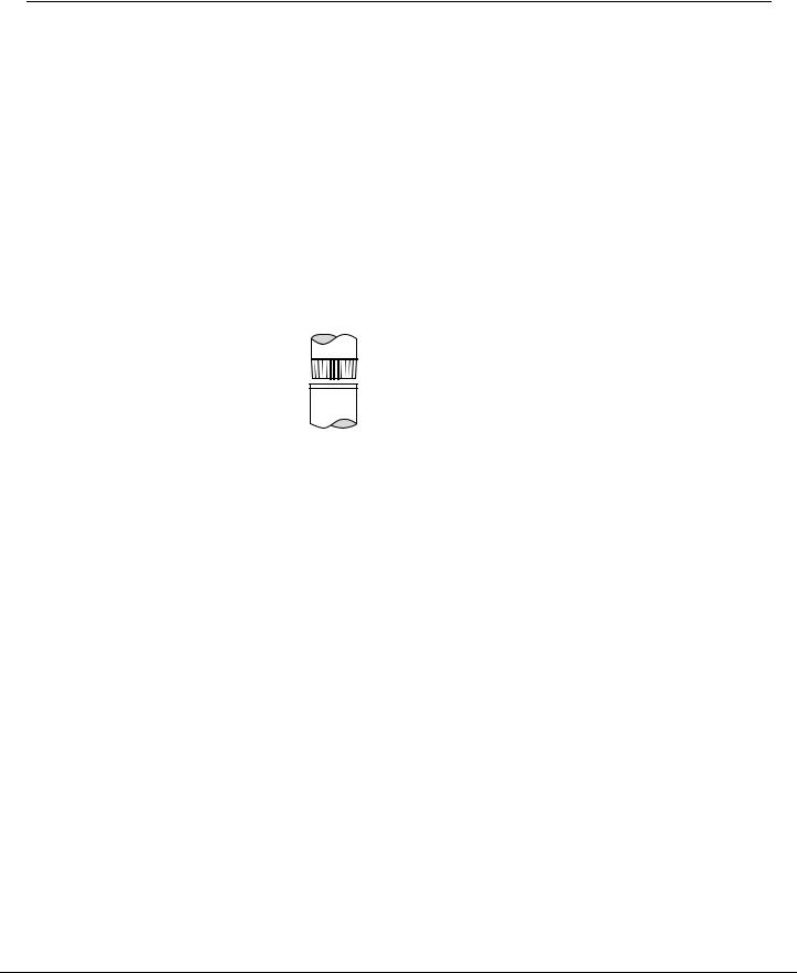
•The chimney connector must be installed with the crimped end pointing downwards (see Figure 4). This prevents creosote from leaking to the exterior of the pipe.
On singlewall pipe
the crimped end
points downward.
Figure 4
•The chimney connector must be fastened to the stove and each adjoining section (and chimney).
© Travis Industries |
100-01179 |
4060926 |
Stove Installation (for qualified installers only) |
11 |
Chimney Requirements
•DO NOT CONNECT THIS UNIT TO A CHIMNEY FLUE SERVING ANOTHER APPLIANCE.
•UL 103 HT Chimney must be used from the first ceiling or floor penetration to the chimney cap.
•Use 6" diameter type UL 103 HT chimney from one manufacturer (do not mix brands) or code approved masonry chimney with a flue liner.
•Chimney must be fastened to each adjoining section.
•Follow the chimney manufacturer's clearances and requirements.
•Use the chimney manufacturer's fire stops, attic guards, roof supports, and flashings when passing through a ceiling
•No more than 180o of elbows (two 90o elbows, or two 45o & one 90o elbow, etc.) may be used for the entire system (connector and chimney).
NOTE: Additional elbows may be allowed if draft is sufficient. Whenever elbows are used the draft is adversely affected. Additional chimney height may be required to boost draft
Chimney Cap (See the section "Chimney Termination Requirements" for more details)
Factory Built Chimney Sections
Floor Penetration Equipment}
(Attic Radiation Shield with Chimney Support)
Reduced Clearance Chimney}
Connector Sections
Floor
Protection
Minimum System 15'
} Maximum System 33'
Roof Penetration Equipment (Roof
Radiation Shield, Flashing, Storm Collar)
Minimum Air Space to Combustibles (See Chimney Manufacturer's Instructions - usually 2")
Standard residential installations with reduced clearance connector may use the clearance determined by the manufacturer of the connector for the connector to wall clearance or the clearance listed in this manual.
Mobile home installations must use the the reduced clearance connector clearances listed in this manual under “Additional Requirements for Mobile Home Installations”.
Stove Clearance
(as outlined in this manual)
|
Figure 5 |
Drafting |
This appliance relies upon natural draft to operate. External forces, such as wind, |
Performance |
barometric pressure, topography, or factors of the home (negative pressure from exhaust |
|
fans, chimneys, air infiltration, etc.), may adversely affect draft. Travis Industries can not be |
|
responsible for external forces leading to less than optimal performance. |
|
|
© Travis Industries |
100-01179 |
4060926 |
 Loading...