


• Masonry Fireplace
• Factory Built (Metal)
Fireplace
• Mobile Home Approved
Tested and Listed by
Omni-Test Laboratories, Inc.
Beaverton, Oregon
Report # 028–S–51-2
ASTME-1509 1995, ULCC 1482
Yankee Bay Pellet Insert
-- Please read this entire manual before installation and use of this pellet fuel-burning room heater. Failure to follow these instructions could result in property damage bodily injury or even death.
-- Contact local building or fire officials about restrictions and
installation inspection requirements in your area.
- - Save these instructions
Installer: After installation give this manual to the home-
|
owner and explain operation of this stove. |
|
|||||
$10.00 |
Copyright 2007, T.I. |
Part # 100-01145 |
|
|
|
|
|
|
|
|
|||||
|
4051228 |
|
|
|
|
|
|
|
|
|
|
|
|
|
|
|
|
|
|
|
|
|
|
4800 Harbour Pointe Blvd. SW
Mukilteo, WA 98275
2 |
Introduction |
Introduction
We welcome you as a new owner of a Yankee Bay pellet heater. In purchasing a Yankee Bay you have joined the growing ranks of concerned individuals whose selection of an energy system reflects both a concern for the environment and aesthetics. The Yankee Bay is one of the finest home heaters the world over. This manual will explain the installation, operation, and maintenance of this pellet-burning heater. Please familiarize yourself with the Owner's Manual before operating your heater and save the manual for future reference. Included are helpful hints and suggestions which will make the installation and operation of your new heater an easier and more enjoyable experience. We offer our continual support and guidance to help you achieve the maximum benefit and enjoyment from your heater.
Important Information
No other Yankee Bay heater has the same serial number as yours. On the Yankee Bay the serial number is on the hopper cover.
This serial number will be needed in case you require service of any type.
Model: |
Yankee Bay |
Serial Number:
Purchase Date:
Purchased From:
Mail your Warranty Card Today, and Save Your Bill of S a l e .
To receive full warranty coverage, you will need to show evidence of the date you purchased your heater. Do not mail your Bill of Sale to us.
We suggest that you attach your Bill of Sale to this page so that you will have all the information you need in one place should the need for service or information occur.
|
|
|
|
|
|
|
|
|
|
|
|
|
|
|
|
|
|
|
|
|
|
|
|
|
|
|
|
|
|
|
|
|
|
|
|
|
|
|
|
|
|
|
|
|
|
|
|
|
|
|
|
|
|
|
|
|
|
|
|
|
|
|
|
|
|
|
|
|
|
|
|
|
|
|
|
|
|
|
|
|
|
|
|
|
|
|
|
|
|
|
|
|
|
|
|
|
|
|
|
|
|
|
|
|
|
|
|
|
|
|
|
|
|
|
|
|
|
|
|
|
|
|
|
|
|
|
|
|
|
|
|
|
|
|
|
|
|
|
|
|
|
|
|
|
|
|
|
|
|
|
|
|
|
|
|
|
|
|
|
|
|
|
|
|
|
|
|
|
|
|
|
|
|
|
|
|
|
|
|
|
|
|
|
|
|
|
|
|
|
|
|
|
|
|
|
|
|
|
|
|
|
|
|
|
|
|
|
|
|
|
|
|
|
|
|
|
|
|
|
|
|
|
|
|
|
|
|
|
|
|
|
|
|
|
|
|
|
|
|
|
|
|
|
|
|
|
|
|
|
|
|
|
|
|
|
|
|
|
|
Travis Industries |
4 0 5 0 5 0 9 |
|
1 0 0 - 0 1 1 4 5 |
||||||||||||||||||||||

Table of Contents |
3 |
Introduction |
|
Introduction ...................................................... |
2 |
Important Information ......................................... |
2 |
Safety Precautions |
|
Safety Precautions ............................................ |
4 |
Specifications |
|
Heating Specifications ........................................ |
6 |
Dimensions....................................................... |
6 |
Electrical Specifications...................................... |
6 |
Fuel................................................................. |
6 |
EPA Compliance ................................................ |
6 |
Installation |
|
Before you Begin ............................................... |
7 |
Packing List...................................................... |
7 |
Installation Options............................................ |
7 |
Planning the Installation ...................................... |
7 |
Minimum Fireplace Size ....................................... |
7 |
Hopper Extension Set-Up .................................... |
8 |
Clearances ....................................................... |
10 |
Mantel Requirements .......................................... |
10 |
Hearth Requirements .......................................... |
10 |
Facing Requirements .......................................... |
10 |
Placing the Insert............................................... |
10 |
Venting the Pellet Stove ...................................... |
11 |
Maximum Venting Distance ............................. |
11 |
Pellet Vent Type............................................ |
11 |
Installing the Pellet Vent................................. |
11 |
Pellet Vent Termination................................... |
11 |
Mobile Home Requirements .................................. |
12 |
Outside Air ....................................................... |
12 |
Restrictor Adjustment ......................................... |
13 |
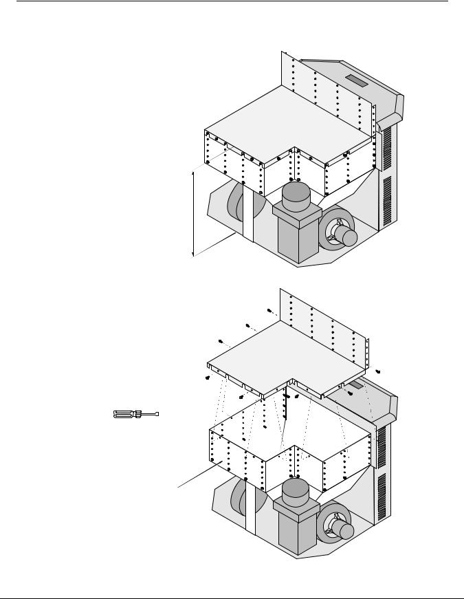
Baffle Installation............................................... |
13 |
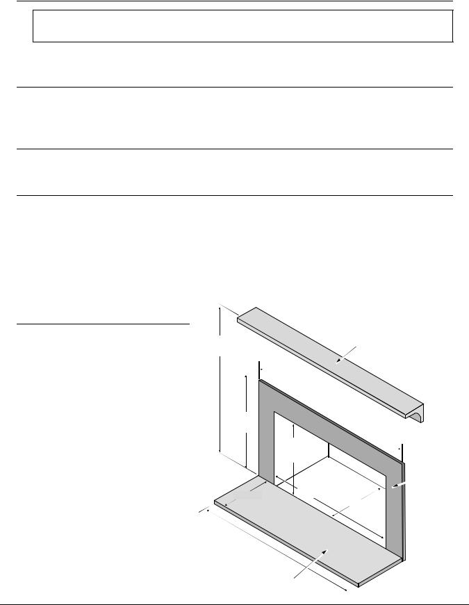
Surround Panel & Circuit Board Installation ............. |
14 |
Installation into a Masonry Fireplace...................... |
15 |
Installation into a Factory Built (Metal) Fireplace....... |
16 |
Operation |
|
Safety Notice .................................................... |
17 |
Location of Controls ........................................... |
17 |
Starting the Heater for the First Time...................... |
17 |
Curing the Paint ............................................ |
17 |
Priming the Auger .......................................... |
17 |
Loading Pellets.................................................. |
18 |
The Two Modes of Operation ................................ |
18 |
Operation (continued) |
|
Manual Mode..................................................... |
19 |
Auto Mode ........................................................ |
20 |
Restrictor Adjustment ......................................... |
21 |
Adjusting the Fan Speed...................................... |
21 |
Start-Up Sequence............................................. |
21 |
"AUGER ON" Light.............................................. |
21 |
"FAULT" Light .................................................... |
22 |
Power Outages.................................................. |
22 |
Maintenance |
|
Daily Maintenance (whenever using the heater)........ |
23 |
Inspect the Burn ........................................... |
23 |
Make Sure Pellets are not Piling Up................... |
23 |
Check Firepot for Clinkers ............................... |
24 |
Cleaning the Firepot....................................... |
24 |
Bi-Weekly Maintenance (or every 10 bags pellets) .... |
25 |
Clean the Heat Exchange Tubes....................... |
25 |
Vacuum Hopper ............................................ |
25 |
Clean the Plated Surfaces............................... |
25 |
Opening the Door .......................................... |
26 |
Check Ashbox and Ashpan, Dispose................. |
27 |
Clean the Glass ............................................ |
27 |
Sweep Ash Into Ashpan.................................. |
28 |
Yearly Maintenance (or every two tons).................. |
29 |
Clean the Exhaust Duct .................................. |
29 |
Clean the Exhaust Blower ............................... |
30 |
Clean the Vent .............................................. |
30 |
Door Seal..................................................... |
31 |
Door Alignment ............................................. |
31 |
Adjusting the Door Hinge and Latch................... |
32 |
Check for Air Leaks - Door, Glass and Ashpan .... |
33 |
Replacement Parts ........................................ |
33 |
Normal Operating Sounds |
|
Normal Operating Sounds.................................... |
34 |
Safety Label |
|
Safety Label ..................................................... |
35 |
Warranty |
|
Warranty .......................................................... |
36 |
Optional Equipment |
|
Thermostat ....................................................... |
37 |
Remote Thermostat............................................ |
38 |
Optional Log ..................................................... |
38 |
Optional Door and Grill ........................................ |
38 |
ZC Kit .............................................................. |
39 |
Index |
|
Index............................................................... |
40 |
Travis Industries |
4 0 5 0 5 0 9 |
1 0 0 - 0 1 1 4 5 |
4
Gas
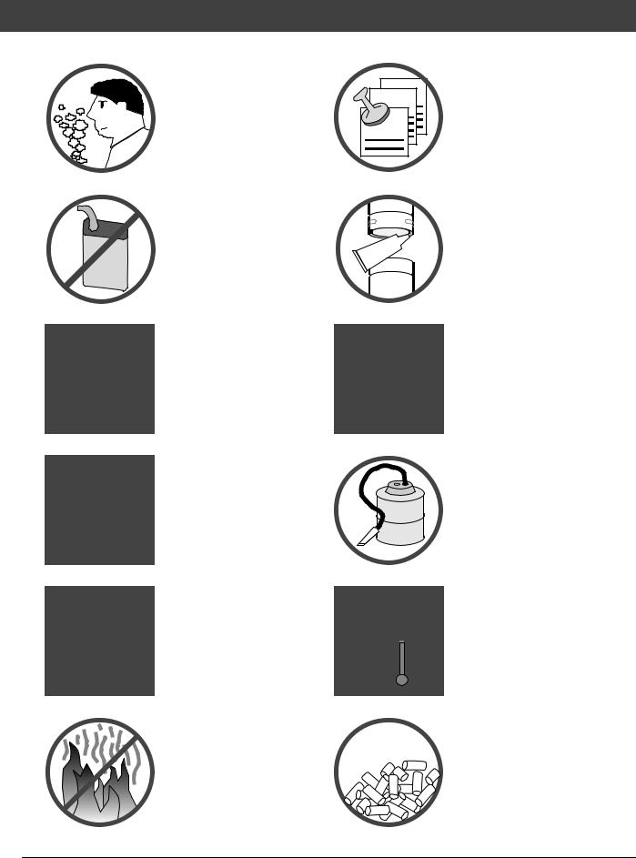
Safety Precautions
• Do not operate the |
|
|||
heater if you smell |
|
|||
smoke coming from |
|
|||
the heater. |
Turn the |
|
||
POWER switch |
to |
Ok |
||
"OFF", |
monitor |
your |
|
|
heater, |
and |
call your |
|
|
dealer . |
|
|
|
|
• Never use gasoline, |
|
|||
gasoline-type lantern fuel, |
|
|||
kerosene, charcoal lighter |
|
|||
fluid, or similar liquids to |
Sealant |
|||
start or 'freshen up' a fire in |
||||
this heater. Keep all such liquids well away from the heater while it is in use.
•Do not unplug the heater if you suspect a malfunction. Turn the MODE SWITCH to "OFF" and monitor the heater (see the “Maintenance” section for details).
•Never try to repair or replace any part of the heater unless instructions are given in this manual. All other work should be done by a trained technician.
•The viewing door and ashpan must be closed and latched during operation.
•Never block free airflow through the open vents of the unit
•Do not operate the heater if the flame becomes dark & sooty of if the firepot overfills with pellets. Turn the MODE SWITCH to "OFF" and and monitor the heater (see the “Maintenance” section for details).
•Contact your local building officials to obtain a permit and information on any installation restrictions or inspection requirements in your area. Notify your insurance company of this heater as well.
•The exhaust system must be completely airtight and properly installed. The pellet vent joints must be sealed with RTV 500o F. (260o C.) silicone sealant.
•This unit must be properly installed to prevent the possibility of a house fire. The instructions must be strictly adhered to. Do not use makeshift methods or compromise in the installation.
•Your heater requires periodic maintenance and cleaning (see "Maintaining Your Heater"). Failure to maintain your heater may lead to smoke spillage in your home.
•Allow the heater to cool before carrying out any maintenance or cleaning. Ashes must be disposed in a metal container with a tight lid and placed on a non-combustible surface well away from the home or structure.
•This heater is designed and approved for pelletized wood fuel only. Any other type of fuel burned in this heater will void the warranty and safety listing (see page 6 for details).
Travis Industries |
4 0 5 0 5 0 9 |
1 0 0 - 0 1 1 4 5 |
Safety Precautions |
5 |
•The heater will not operate during a power outage. If
a power outage does occur, check the heater for smoke spillage and open a window if any smoke spills into the room.
• |
Keep foreign objects out |
? |
of the hopper. |
Mobile

 Home
Home
•Disconnect the power cord before performing any maintenance.
N O T E :
Turning the Mode Switch to "OFF" does not disconnect all power to the heater.
• Do not throw this manual away. This manual has important operating and maintenance instructions that you will need at a later time. Always follow the instructions in this manual.
• Do not place clothing or other flammable items on or near the heater. Because this heater can be controlled by a thermostat there is a possibility of the heater turning on and igniting any items placed on or near it.
•This heater must be connected to a standard 115 V., 60 Hz grounded electrical outlet. Do not use an adapter plug or sever the grounding plug. Do not route the electrical cord underneath, in front of, or over the heater.
•When installed in a mobile home, the heater must have outside air, and NOT
BE INSTALLED IN THE BEDROOM.
•The exhaust system should be checked twice a year minimum for any build-up of soot or creosote.
•Do not touch the hot surfaces of the heater. Educate all children of the danger of a hightemperature heater. Young children should be supervised when they are in the same room as the heater.
•Travis Industries, Inc. grants no warranty, implied or stated, for the installation or maintenance of your heater, and assumes no responsibility of any consequential damage(s).
Travis Industries |
4 0 5 0 5 0 9 |
1 0 0 - 0 1 1 4 5 |
6 |
Specifications |
Heating Specifications:
Approximate Maximum Heating Capacity (in square feet)* ........................................ |
800 to 2,250 |
Burn Rate (Pounds per Hour)**............................................................................ |
1.7 to 5.5 |
Maximum Burn Time on Low Burn** ...................................................................... |
28 to 52 Hours |
Hopper Capacity (based upon hopper extension position)......................................... |
48 to 89 Pounds |
*Heating capacity will vary depending on the home's floor plan, degree of insulation, and the outside temperature. It is also affected by the fuel size, quality, and moisture level.
**Small pellets will increase or decrease the stated burn rates and burn times. Differences of plus or minus 20% depending on fuel quality may occur.
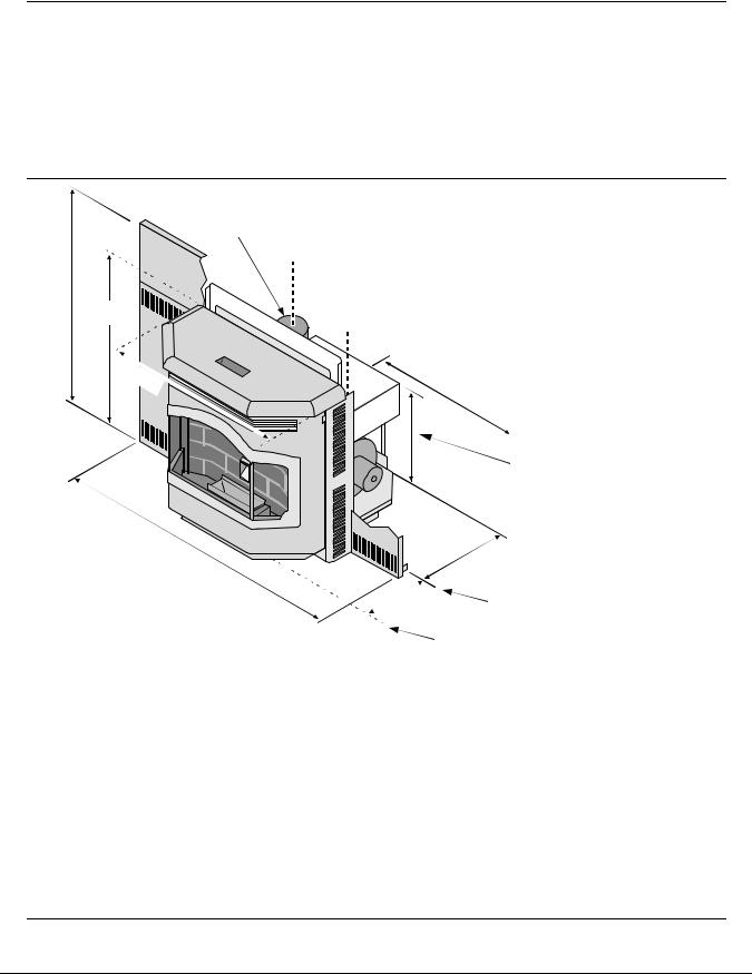
Dimensions:
32”
26-1/2”
28”
Center of 4” diameter Flue is 16-7/8” above the baseplate and 7-1/2” left of center
25-1/2” (allow 36” width for control board installation)
25-3/4” to 20”
See “Hopper Extension Set-up” for details.
45” |
13-1/4” (allow 14” depth in the Fireplace) |
|
|
12" |
Fireplace Opening |
|
Door Opening |
Electrical Specifications: |
|
Electrical Rating......................................................................................... |
115 Volts, 3.6 Amps, 60 Hz |
Watts During Start-Up Sequence................................................................... |
400 (approximately) |
Watts During Operation ............................................................................... |
180 (approximately) |
Fuel: |
|
The unit is designed for wood pellets that comply with the standards set by the Association of Pellet Fuel Industry (density of at least 40 lbs. per cubic foot, 1/4" to 5/16" diameter, length no greater than 1–1/2", 8200
BTU's/lb., moisture under 8% by weight, ash under 1% by weight, and salt under 300 parts per million). If the fuel does not comply to this standard, the unit may not operate as designed.
N O T E: This heater may use alternative fuel if equipped with the multi-fuel fire pot and properly maintained. See the publication “Multi-Fuel Pellet Fire Pot” for requirements (available from your Travis Industries, Inc. dealer).
EPA Compliance:
This heater is EPA exempt from Phase II requirements, but has been tested for emissions using EPA test methods by OMNI Test Labs.
Travis Industries |
4 0 5 0 5 0 9 |
1 0 0 - 0 1 1 4 5 |
Installation |
7 |
Before You Begin
READ THIS ENTIRE MANUAL BEFORE YOU INSTALL AND USE THIS HEATER. FAILURE TO FOLLOW THE INSTRUCTIONS MAY RESULT IN PROPERTY DAMAGE, BODILY INJURY, OR EVEN DEATH.
Check with local building officials for any permits required for installation of this pellet heater and notify your insurance company before proceeding with installation.
Packing List
• Thermostat & Wire |
• Scraper Rod Tool |
• Fuses (2) • Fireplace Installation Sticker • Brush |
• Leveling Bolts (2) |
• Control Board Screws |
• Hopper Screws • Double-Back Tape (for panels) |
Installation Options:
• Masonry Fireplace • Factory Built (Metal) Fireplace • Outside Air Compatible
Planning The Installation
•Have an authorized Travis Industries dealer install this heater. If you install the heater yourself, have your dealer review your installation plans.
•Place the heater outside and load 10 pounds of pellets inside the hopper. Plug the heater in and let it run on HIGH until the pellets run out. This will cure the paint and burn off any oil on the steel, eliminating any smell inside the home.
•Inspect the chimney and clean as necessary before installing the heater. NOTE: The convection blower is open to the fireplace cavity and may circulate odors from the fireplace. You may wish to paint the interior of the fireplace with latex paint to prevent odors from entering the home.
Minimum Fireplace Size
Mantel
See "Mantel (combustible or non-combustible) Requirements" for
details
Min.42"
(7" from hopper Min. 32-3/4" lid) (6-1/4" from
hopper lid)
25-3/4” - 20” See
“Hopper Extension
Set-up”
Non-Combustible
Facing
Min. 36"
(includes circuit board)
Min. 18"
Min. 14"
Min. 36" (6" from door opening)
Non-Combustible Hearth
Travis Industries |
4 0 5 0 5 0 9 |
1 0 0 - 0 1 1 4 5 |
8 |
Installation |
Hopper Extension Set-up
This pellet heater has a variable-height hopper. This allows the hopper to be lowered for smaller fireplaces. Follow the instructions below to set the correct hopper extension position.
•Determine the correct hopper extension position following the directions below.
The unit will extend 14” into the fireplace. For setting the hopper, the maximum fireplace opening measurements have to be taken at 14” into the fireplace.
Hopper Extension Position
A (highest position) |
25-3/4” |
B (next highest) |
24-1/2” |
C etc... |
23-3/8” |
D etc... |
22-1/4” |
E etc... |
21-1/8” |
F (lowest position) |
20” |
•Remove the hopper top following the directions below.
Hopper Top
Remove the hopper top by removing the screws holding it in place.
1/4" Nutdriver
NOTE: with the hopper top removed, the hopper walls may be removed.
•Remove the hopper walls.
Travis Industries |
4 0 5 0 5 0 9 |
1 0 0 - 0 1 1 4 5 |

Installation |
9 |
•Remove the correct knock-outs in the hopper walls following the directions below.
If you are using hopper extension position F, remove the top knock-out. If using position E, remove the second knock-out, (etc...). The second-to-bottom knock-out is position B.
Position F Knock-Out
Position E Knock-Out
Position D Knock-Out
Position C Knock-Out
Position B Knock-Out
Position A Knock-Out
Use a center-punch (or other suitable tool) to remove the appropriate knockouts in the hopper walls (punch the holes out from the inside). Make sure to support the hopper walls while removing the knock-outs. There are 11 knock-outs for each position.
•Re-install the hopper walls following the directions below.
HINT: Attach one screw to each side to align the hopper walls. Then install the remaining screws.
NOTE: This hopper extension is in position D.
•Attach the hopper top following the directions below.
Before installing the hopper top, use a centerpunch (or other suitable tool) to remove the appropriate knock-outs on the hopper top.
Re-attach the hopper top to the hopper walls using the screws included with the insert.
Travis Industries |
4 0 5 0 5 0 9 |
1 0 0 - 0 1 1 4 5 |
1 0 |
Installation |
Clearances
•Insert must be placed so that no combustibles are within, or can swing within (e.g. drapes, doors), 36" of the front of the heater.
•Insert must be placed a minimum 8-3/4" from a side wall (or combustible protruding more than 3/4").
Mantel Requirements
•The mantel must meet the requirements shown in the illustration to the right.
12”
The mantel must fall within this shaded area (or above). Maximum mantel depth is 12”.
Hearth Requirements |
3-1/2” |
|
|
||
• The non-combustible hearth must extend 6” |
|
|
to the front and sides of the firebox opening |
33” |
|
(you must open the door to measure). |
||
|
||
Facing Requirements |
38” |
|
|
||
• The non-combustible facing must extend 7" |
|
|
to the side and 6" above the hopper lid. |
|
|
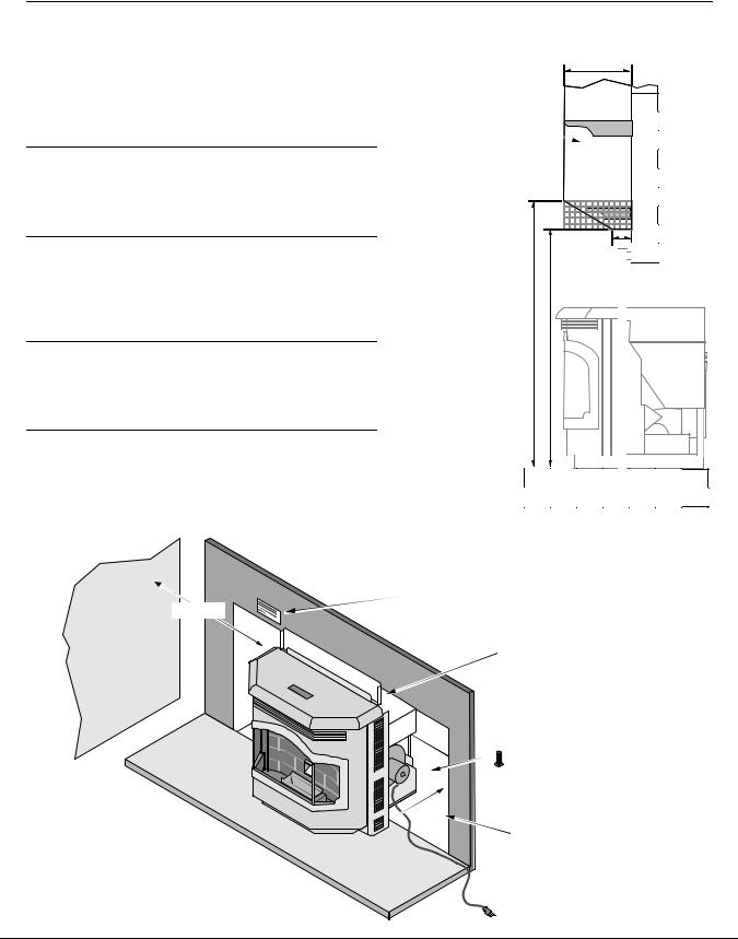
Placing the Insert |
|
|
• The insert must be placed within an |
|
|
undamaged masonry or factory built (metal) |
|
|
fireplace. Loose bricks or other damage must |
|
|
be fixed. Clean the fireplace before |
|
|
installing. |
|
Min. 8-3/4"
Side Wall
Apply the "This fireplace has been altered..." sticker to the fireplace. You may wish to place it in a location where it will be covered by the surround panels.
The vent should be routed to the fireplace prior to installing the insert. See the section "Vent Installation" for details on vent location.
 13-1/4"
Use the leveling bolts for fireplaces with recessed floors (included with the insert). Screw them into the baseplate from below.
Place the insert so the back edge of the baseplete extends 13-1/4" into the fireplace.
 Run the power cord to the side along the front of the fireplace (do not route it under the insert).
Travis Industries |
4 0 5 0 5 0 9 |
1 0 0 - 0 1 1 4 5 |
Installation |
1 1 |
Venting the Pellet Stove
•PELLET VENT MUST MAINTAIN A MINIMUM 3" CLEARANCE TO ANY COMBUSTIBLE (INSTALL VENT AT CLEARANCES SPECIFIED BY THE VENT MANUFACTURER).
•DO NOT CONNECT THE PELLET VENT TO A VENT SERVING ANY OTHER APPLIANCE OR STOVE.
•DO NOT INSTALL A FLUE DAMPER IN THE EXHAUST VENTING SYSTEM OF THIS UNIT.
Maximum Venting Distance:
•Maximum venting height is 33' (maximum horizontal offset is 10')
•Use no more than 180° of elbows (two 90° elbows, or two 45° & one 90° elbow, etc.).
Pellet Vent Type
•Must be Type "L" vent and/or Type "L" chimney liner.
•Use 4" diameter vent.
Installing the Pellet Vent
•Pellet vent connections must be sealed airtight with 500° F. RTV silicone and screwed together with at least three sheet metal screws.
.RTV °F 500Silicone 
Seal each vent section (including adapters, elbows, etc...) by injecting a liberal amount of 500° F. RTV silicone into the gap between sections.
The exhaust quick- 
 connect can be
 removed to allow for

 installation and


 cleaning.


Pellet Vent Termination
•Termination must be a minimum 6" above the top of the chimney (NOTE: the chimney must meet local codes for height above the roof or other obstructions).
•Must have an approved cap (to prevent water from entering).
•Must not be located where it will become plugged by snow or other material.
Travis Industries |
4 0 5 0 5 0 9 |
1 0 0 - 0 1 1 4 5 |
1 2 |
Installation |
Mobile Home Requirements
•Outside air is required (used for combustion) - see the directions below.
WARNING: DO NOT INSTALL IN SLEEPING ROOM.
CAUTION: THE STRUCTURAL INTEGRITY OF THE MANUFACTURED HOME FLOOR, WALL, AND CEILING/ROOF MUST BE MAINTAINED.
Outside Air (used for combustion)
•Outside air is optional (except in mobile homes or when required by local building codes).
•Must not be drawn from an enclosed space (garage, unventilated crawl space).
•Must not be over 15' long.
•Must be made with 1 3/4" diameter or larger metal or aluminum duct with a metal screen attached to the end to keep out rodents (P.V.C. or other combustible materials may not be used). Use the Travis Industries Outside Air Kit (part # 99200136).
•Must not terminate above or within 1' of the chimney termination.
•Must have a rain cap or down-turned elbow to prevent water from entering.
•Must be located so that it will not become plugged by snow or other material.
12” Min. |
Vent Termination |
|
Outside air may be drawn
through the chimney (15’ maximum length).
|
Outside air may be drawn |
|
|
|
from the ash cleanout. |
|
|
Travis |
Industries |
4 0 5 0 5 0 9 |
1 0 0 - 0 1 1 4 5 |
 Loading...