


TM
Answer
Wood Stove
|
Owner's Manual |
|
• Freestanding |
Stove |
|
• Mobile-Home |
Approved |
|
• Alcove Approved |
||
• |
Hearth-Stove |
Approved |
• |
Masonry Fireplace Insert |
|
• Zero-Clearance (Metal)
Fireplace Insert
SAFETY NOTICE:
If this appliance is not properly installed, a house fire may result. For your safety, follow the installation directions. Contact local building or fire officials about restrictions and installation inspection requirements in your area.
|
10850 117th Place N.E. Kirkland, WA 98033 |
|
Listed |
93508131 |
Copyright 2001, T.I. |
$10.00 |
Tested to: U.L. 1482 |
4020327
2 |
Introduction |
Introduction
We welcome you as a new owner of a Lopi Answer wood-burning stove. In purchasing a Lopi Answer you have joined the growing ranks of concerned individuals whose selection of an energy system reflects both a concern for the environment and aesthetics. The Lopi Answer is one of the finest appliances the world over. This manual will explain the installation, operation, and maintenance of this appliance. Please familiarize yourself with the Owner's Manual before operating your appliance and save the manual for future reference. Included are helpful hints and suggestions which will make the installation and operation of your new appliance an easier and more enjoyable experience. We offer our continual support and guidance to help you achieve the maximum benefit and enjoyment from your appliance.
Important Information
No other Lopi Answer appliance has the same serial number as yours. The serial number is stamped onto the label on the back of the appliance.
This serial number will be needed in case you require service of any type.
Model: |
Lopi Answer |
Serial Number:
Purchase Date:
Purchased From:
Mail your Warranty Card Today, and Save Your Bill of Sale.
To receive full warranty coverage, you will need to show evidence of the date you purchased your appliance. Do not mail your Bill of Sale to us.
We suggest that you attach your Bill of Sale to this page so that you will have all the information you need in one place should the need for service or information occur.
Travis Industries |
93508131 |
4 020327 |

Table of Contents |
3 |
General Information |
|
|
Introduction & Important Information ...................... |
2 |
|
Safety Precautions ............................................. |
4 |
|
Features & Specifications .................................... |
6 |
|
Stove |
Installation |
|
Planning The Installation ..................................... |
7 |
|
Floor Protection Requirements.............................. |
8 |
|
Stove Placement Requirements ............................ |
9 |
|
Clearances ....................................................... |
9 |
|
Chimney Requirements ....................................... |
10 |
|
Chimney Termination Requirements ...................... |
11 |
|
Outside Air Requirements .................................... |
11 |
|
Alcove Installation Requirements........................... |
12 |
|
Mobile Home Requirements ................................. |
13 |
|
INSTALLATION DIAGRAMS |
|
|
Standard Ceiling with a Factory Built Chimney..... |
14 |
|
Cathedral Ceiling with a Factory Built Chimney.... |
14 |
|
Exterior Factory Built Chimney ......................... |
15 |
|
Hearth Stove Positive Connection..................... |
15 |
|
Hearth Stove Direct Connection ....................... |
16 |
|
Interior Masonry Chimney ............................... |
16 |
|
Insert |
Installation |
|
Planning The Installation ..................................... |
17 |
|
Insert Size Requirements..................................... |
18 |
|
Insert Placement Requirements ............................ |
18 |
|
Hearth Requirements.......................................... |
18 |
|
Masonry Fireplace Requirements .......................... |
19 |
|
Zero Clearance (Metal) Fireplace Requirements....... |
19 |
|
Drafting Performance.......................................... |
19 |
|
Leveling Bolt Installation ...................................... |
19 |
|
Block-Off Plate Installation ................................... |
20 |
|
INSTALLATION DIAGRAMS |
|
|
Insert with Positive Connection......................... |
21 |
|
Insert with Direct Connection (Masonry Fireplace)21 |
||
Insert with Direct Connection (ZC Fireplace) ....... |
22 |
|
Insert with Face Seal Connection...................... |
22 |
|
Operating |
Your Appliance |
|
Safety Notice .................................................... |
23 |
|
Before Your First Fire.......................................... |
23 |
|
Opening the Door............................................... |
23 |
|
Starting a Fire ................................................... |
24 |
|
Adjusting the Burn Rate....................................... |
25 |
|
Ash Removal .................................................... |
25 |
|
Optional Blower Operation ................................... |
26 |
|
Re-Loading the Stove ......................................... |
26 |
|
Overnight Burn .................................................. |
26 |
|
Normal Operating Sounds.................................... |
26 |
|
Hints for Burning ................................................ |
27 |
|
Selecting Wood ................................................. |
27 |
|
Dry Wood is Key ........................................... |
27 |
|
Testing Wood Moisture................................... |
27 |
|
Why Dry Wood is Key..................................... |
27 |
|
Wood Cutting and Storage .............................. |
27 |
|
Troubleshooting................................................. |
28 |
|
Maintaining Your Appliance |
|
|
Daily Maintenance.............................................. |
29 |
|
Remove Ash ................................................ |
29 |
|
Clean The Glass ........................................... |
29 |
|
Monthly Maintenance.......................................... |
30 |
|
Door and Glass Inspection .............................. |
30 |
|
Check For Creosote Buildup ............................ |
30 |
|
Yearly Maintenance............................................ |
31 |
|
Touch Up Paint ............................................. |
31 |
|
Blower Cleaning............................................ |
31 |
|
Firebrick and Baffle Inspection ......................... |
31 |
|
Door Parts ........................................................ |
|
32 |
Replacing the Glass....................................... |
32 |
|
Replacing the Door Gasket.............................. |
32 |
|
Replacing the Door Handle.............................. |
32 |
|
Firebox Parts .................................................... |
33 |
|
Floor & Side Firebrick Removal & Replacement... |
33 |
|
Baffle Removal and Replacement ..................... |
34 |
|
Air Tube Removal and Replacement ................. |
34 |
|
Warranty |
|
|
Warranty .......................................................... |
|
35 |
Listing Information |
|
|
Listing Information.............................................. |
36 |
|
Optional |
Equipment |
|
Stove Legs ....................................................... |
|
37 |
Pedestal........................................................... |
|
37 |
Rear Blower Installation....................................... |
39 |
|
Outside Air Boot Installation ................................. |
40 |
|
Surround Panels ................................................ |
41 |
|
Front Blower |
..................................................... |
43 |
Index |
|
|
Index ............................................................... |
|
44 |
Travis Industries |
93508131 |
4 020327 |
4 |
Safety Precautions |
•The viewing door must be closed and latched during operation.
•Never block free airflow through the air vents on this appliance.
•This appliance is designed and approved for the burning of cord wood only. Do not attempt to burn any other type of fuel other than cord wood in this appliance, it will void all warranties and safety listings.
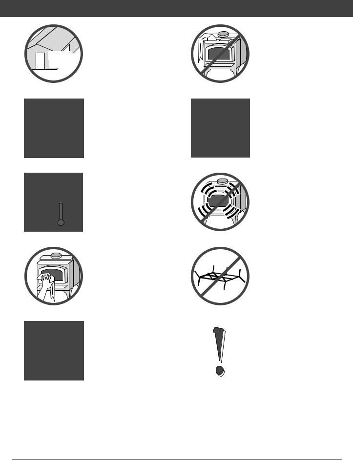
•Do not touch the appliance while it is hot and educate all children of the danger of a high-temperature appliance. Young children should be supervised when they are in the same room as the appliance.
•This appliance must be properly installed to prevent the possibility of a house fire. The instructions must be strictly adhered to. Do not use makeshift methods or compromise in the installation.
•Inspect the chimney connector and chimney at least twice monthly and clean if necessary. Creosote may build up and cause a house fire.
•Do not connect this appliance to any chimney serving another appliance.
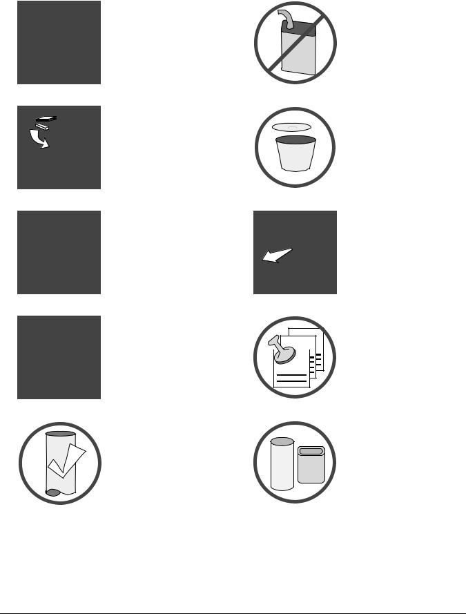
•Gasoline or other flammable liquids must never be used to start the fire or "Freshen Up" the fire. Do not store or use gasoline or other flammable liquids in the vicinity of this appliance.
•Ashes must be disposed in a metal container with a tight lid and placed on a
non-combustible surface ASHES well away from the home or
structure.
•Keep furniture, drapes,
|
curtains, wood, paper, and |
|
other combustibles a |
|
minimum of 36" away from |
36" |
the front of the appliance. |
•Contact your local building
officials to obtain a permit and information on any
 installation restrictions or Ok inspection requirements in
your area. Notify your insurance company of this appliance as well.
•This appliance must be connected to a listed high
Type |
Clay |
temperature (UL 103 HT) |
|
residential type chimney or |
|||
HT |
|||
Liner |
an approved masonry |
||
|
|||
|
|
chimney with a standard |
|
|
|
clay tile, or stainless steel |
|
|
|
liner. |
Travis Industries |
93508131 |
4 020327 |
Mobile
Home
Safety Precautions |
5 |
•When installed in a mobile home, this appliance must be bolted to the floor, have outside air, and not be installed in the bedroom (Per H.U.D. requirements). Check with local building officials.
•Do not place clothing or other flammable items on or near this appliance.
•Never try to repair or replace any part of this appliance unless instructions are given in this manual. All other work must be done by a trained technician.
•Allow the appliance to cool before carrying out any maintenance or cleaning.
•Maintain the door and glass seal and keep them in good condition.
•Avoid placing wood against the glass when loading. Do not slam the door or strike the glass.
•Do not make any changes or modifications to an existing masonry fireplace or chimney to install this appliance.
•Do not make any changes to the appliance to increase combustion air
•Overfiring the appliance may cause a house fire. If a unit or chimney connector glows, you are overfiring.
•Do not use a grate or other device to elevate the fire off of the firebox floor. Burn the fire directly on the bricks.
• Do not throw this manual |
|
• Travis |
Industries, Inc. |
||
away. This manual has |
|
grants |
no |
warranty, |
|
important operating and |
|
implied |
or |
stated, for |
|
maintenance instructions |
|
the installation |
or |
||
that you will need at a later |
|
maintenance of |
your |
||
time. Always follow the |
|
appliance, |
and |
|
|
instructions in this manual. |
|
assumes no |
|
||
|
|
responsibility of |
any |
||
|
|
consequential |
|
||
|
|
|
|||
|
|
damage(s). |
|
||
Travis Industries |
93508131 |
4 020327 |
6 |
Features & Specifications |
Installation Options:
•Freestanding
•Freestanding in an Alcove
•Freestanding in a Mobile Home
•Masonry Fireplace Insert
•Factory-Built (Z.C.) Fireplace Insert
Features:
•EPA Phase II Approved
•1.6 Cubic Foot Firebox Volume
•Single Operating Control
•Accepts Logs Up to 18" Long
•Steel Plate Construction (5/16" & 3/16")
•Heavy Duty Refractory Firebrick
•Optional High-Tech Blower
Heating Specifications:
Approximate Maximum Heating Capacity (in square feet)* |
750 to 1,400 (stove) |
|
750 to 1,200 (insert) |
Maximum BTU's per Hour (Cord Wood Calculation) |
66,800 |
Overall Efficiency (Oregon Method) |
70.0 % |
Maximum Burn Time |
Up to 8 Hours |
*Heating capacity will vary depending on the home's floor plan, degree of insulation, and the outside temperature. It is also affected by the quality and moisture level of the fuel.
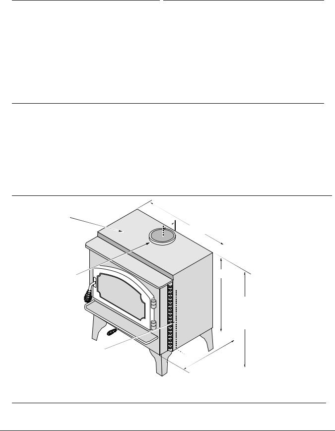
Dimensions:
Note:
Measure side, corner,
and back clearances
5-7/8"
from the stove top.
The flue collar protrudes 3/4" above the stove top
Insert Dimensions: |
|
Depth into Fireplace** ........ |
13-1/2" |
Onto Hearth*** .................... |
3" |
*For inserts, add 3/4" for the flue collar.
**ZC (metal) fireplaces requre 14-1/2".
***Does not include hearth protection.
23-5/8"
Height:
Steel Legs (discontinued)..26-1/2"
Sculptured or Cast Legs.... |
27-7/8" |
Pedestal............................. |
31-7/8" |
16-1/4"
Emissions:
3.3 Grams Per Hour (EPA Phase II Approved) – Tests conducted by E.E.S.P.C.
Travis Industries |
93508131 |
4 020327 |

Stove Installation (for qualified installers only) |
7 |
SAFETY NOTICE:
Please read this entire manual before you install and use your new room heater. Failure to follow instructions may result in property damage, bodily injury, or even death. Contact local building or fire officials about restrictions and installation inspection requirements in your area.
Planning The Installation
We suggest that you have an authorized Travis Industries dealer install your stove. If you install the stove yourself, your authorized dealer should review your plans for installation.
Check with local building officials for any permits required for installation of this stove and notify your insurance company before proceeding with installation.
Preparation for Installation
•Check for damage to the exterior of the stove (dents should be reported, scratches can be fixed by applying touch up paint).
•Check the interior of the firebox (replace cracked firebrick and make sure baffle is in place).
The stove can be lightened by removing the firebricks and baffle. (pg 26) - replace before operation.
Stove Installation Considerations
The table below details the six most common types of installations and the considerations for each type. Alternative methods of installation are available if they comply with local building codes.
Installation Type |
Considerations |
|
|
Standard Ceiling with a Factory Built Chimney |
• Requires ceiling and roof penetration |
(Page 14) |
• Provides best draft |
|
|
|
|
Cathedral Ceiling with a Factory Built Chimney |
• Cathedral style chimney support required |
(Page 14) |
• Provides best draft |
|
|
|
|
Exterior Factory Built Chimney |
• Uses two elbows to route chimney outside |
(Page 15) |
• Exterior chimney is hidden from the room |
|
|
|
• Elbows reduce draft |
|
• Optional exterior chase reduces cold air blockage |
|
|
Hearth Stove Positive Connection |
• Utilizes existing masonry or zero clearance (metal) chimney |
(Page 15) |
• Provides good draft due to full reline |
|
|
|
• Easier to clean than direct or horizontal hearth stove |
|
|
Hearth Stove Direct Connection |
• Utilizes existing masonry or zero clearance (metal) chimney |
(Page 16) |
• Requires construction of a "block-off plate" |
|
|
|
• Draft reduced due to elbows & chimney cross section |
|
|
Interior Masonry Chimney |
• Utilizes existing masonry chimney (not approved for zero |
(Page 16) |
clearance (metal) fireplaces) |
|
|
Travis Industries |
93508131 |
4 020327 |
8 |
Stove Installation (for qualified installers only) |
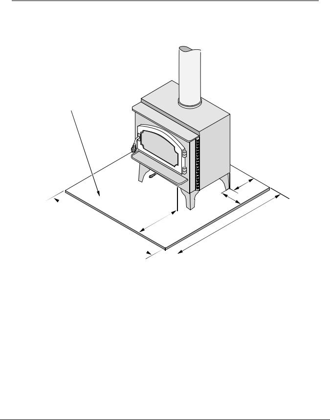
Floor Protection Requirements
•Stove must be placed on the Travis Industries legs or Pedestal.
•Must be non-combustible and at least .018" thick (26 gauge)
Floor protection must be non-combustible and at least
.018" thick (26 gauge).
Min. 6”
|
Min. 6” |
|
Min. 16” |
Minimum |
Minimum 38-1/4” |
|
|
35-5/8” |
|
Travis Industries |
93508131 |
4 020327 |
Stove Installation (for qualified installers only) |
9 |
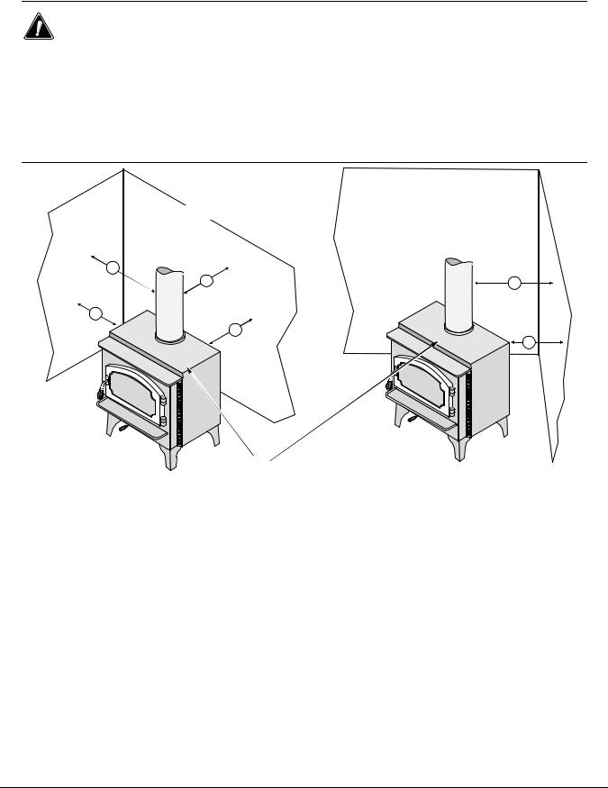
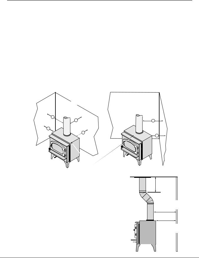
Stove Placement Requirements
Clearances may be reduced by methods specified in NFPA 211, listed wall shields, pipe shields, or other means approved by local building or fire officials.
•Stove must be placed so that no combustibles are within, or can swing within (e.g. drapes, doors), 36" of the front of the stove
•If the stove is placed in a location where the ceiling height is less than 7', it must follow the requirements in the section "Alcove Installation Requirements"
•Must maintain the clearances to combustibles listed below (drywall, furniture, etc.):
Clearances
Corner Installations
Straight Installations
d
e |
f |
a
b
c
NOTE:
Measure clearances to the stove top.
Minimum |
Clearance |
Singlewall |
Reduced |
|
(See |
the |
illustration below) |
Connector |
Clearance* |
A |
Sidewall to stove |
18" |
13" |
|
B |
Backwall to stove |
16 1/2" |
9" |
|
C |
Cornerwall to stove |
10" |
7 1/2" |
|
D |
Connector to sidewall |
27" |
21 1/2" |
|
E |
Connector to backwall |
19 1/2" |
11 1/2" |
|
F |
Connector to cornerwall |
19 1/2" |
16 1/2" |
|
*Reduced clearance installations require one of |
the chimneys and connectors listed below: |
• DURAVENT model DVL with DURATEC chimney |
• GSW Double Wall Chimney Connector with Super Chimney Twenty-One |
• DURAVENT model DVL with DURA-PLUS chimney |
• SELKIRK METALBESTOS model DS connector with model SSII chimney |
• AMERI-TEC model DCC with model HS chimney |
• I.C.C. Excel (2100-2 Can.) (103-HT USA) chimney with HP connector |
• SECURITY model DL with SECURITY model ASHT or S2100 chimney |
• Standard Masonry Chimney with any one of the above listed connectors |
• METAL-FAB model DW with TG chimney |
|
NOTE: Standard residential installations with reduced clearance connector may use the clearance determined by the manufacturer of the connector for the connector to wall clearance or the clearance listed in this manual. Offsets must be used to maintain the stove to wall clearance.
NOTE: Reduced clearance connectors may not connect to the flue collar – order an appliance adapter for the connector being used.
Travis Industries |
93508131 |
4 020327 |
10 Stove Installation (for qualified installers only)
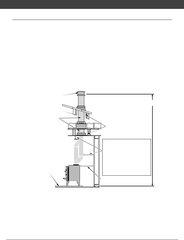
Chimney Requirements
•DO NOT CONNECT THIS UNIT TO A CHIMNEY FLUE SERVING ANOTHER APPLIANCE.
•Chimney connector must be a minimum 24 MSG black or 26 MSG blued steel (6" diameter). Chimney must be used from the first floor or wall penetration to the chimney cap.
•Use 6" diameter type UL 103 HT chimney from one manufacturer (do not mix brands) or code approved masonry chimney with a flue liner.
•Chimney connector and chimney must be fastened to the stove and each adjoining section.
•Follow the chimney manufacturer's clearances and requirements.
•Use the chimney manufacturer's fire stops, attic guards, roof supports, and flashings when passing through a ceiling or thimble when passing through a combustible wall.
•No more than 180o of elbows (two 90o elbows, or two 45o & one 90o elbow, etc.).
NOTE: Additional elbows may be allowed if draft is sufficient. Whenever elbows are used the draft is adversely affected. Additional chimney height may be required to boost draft
Chimney Cap |
|
|
|
(See the section |
|
|
|
"Chimney Termination |
|
|
|
Requirements" for |
|
} |
Minimum System 15' |
more |
|
||
|
|
Maximum System 33' |
|
|
|
Roof Penetration Equipment |
|
|
|
(Roof Radiation Shield, |
|
Factory Built |
|
Flashing, Storm Collar) |
|
|
|
||
Chimney |
|
|
|
Sections |
} |
|
|
Floor Penetration |
|
Minimum Air Space to |
|
Equipment (Attic |
|
|
Combustibles (See |
Radiation Shield with |
|
Chimney Manufacturer's |
|
Chimney Support) |
|
|
Instructions - usually 2") |
|
} |
Standard residential installations with |
Reduced |
|
reduced clearance connector may use the |
|
clearance determined by the manufacturer |
|
Clearance |
|
of the connector for the connector to wall |
Chimney |
|
|
|
clearance or the clearance listed in this |
|
Connector |
|
manual. |
Sections |
|
|
|
Mobile home installations must use the |
|
|
|
|
|
|
the reduced clearance connector |
|
|
clearances listed in this manual under |
|
|
“Additional Requirements for Mobile Home |
|
|
Installations”. |
Floor |
|
|
Protection |
|
|
|
|
Stove Clearance |
|
|
(as outlined in this manual) |
Drafting |
This appliance relies upon natural draft to operate. External forces, such as wind, |
Performance |
barometric pressure, topography, or factors of the home (negative pressure from exhaust |
|
fans, chimneys, air infiltration, etc.), may adversely affect draft. Travis Industries can not be |
|
responsible for external forces leading to less than optimal performance. |
•Standard residential installations may use single-wall connector (Mobile-Homes may n o t)
•Standard residential installations with reduced clearance connector may use the clearance determined by the manufacturer of the connector for the connector to wall clearance or the clearance listed in this manual. Offsets must be used to maintain the stove to wall clearance. Mobile homes must use the clearances listed in this manual under "Additional Requirements for Mobile Home Installations".
Travis Industries |
93508131 |
4 020327 |
Stove Installation (for qualified installers only) |
11 |
Chimney Termination Requirements
•Must have an approved cap (to prevent water from entering)
•Must not be located where it will become plugged by snow or other material
•Must terminate at least 3' above the roofa n d at least 2' above any portion of the roof within 10'
Slanted Roofs
Chimney must extend 3' above the roof
Chimney must extend 2' above any portion of the roof within 10' of the chimney
Flat
Chimney must extend 3' above the roof
Chimney must extend 2' above any portion of the roof within 10' of the chimney
Outside Air Requirements
•Required for mobile homes & in certain localities (check with building officials)
•Must not be drawn from an enclosed space (garage, unventilated crawl space)
•Requires the optional outside air boot (for legs) or pedestal
When using outside air, find a location where the chimney and outside air hole do not interfere with structural members of the home
Pedestal (with insulation) |
directs air to the stove. |
Air may be drawn from a ventilated crawl space or use an air duct.
A hole must be cut |
|
through the floor |
Outside |
protection and floor |
Air Boot |
and the rodent |
|
screen nailed in |
|
place here (see the |
|
optional equipment |
|
instructions for |
|
exact sizes) |
|
Optional Air Duct (must not be longer than 15' and at least 16 square inches in cross section)
Outside air entrance must be placed so it does not become blocked by snow.
Travis Industries |
93508131 |
4 020327 |
12 Stove Installation (for qualified installers only)
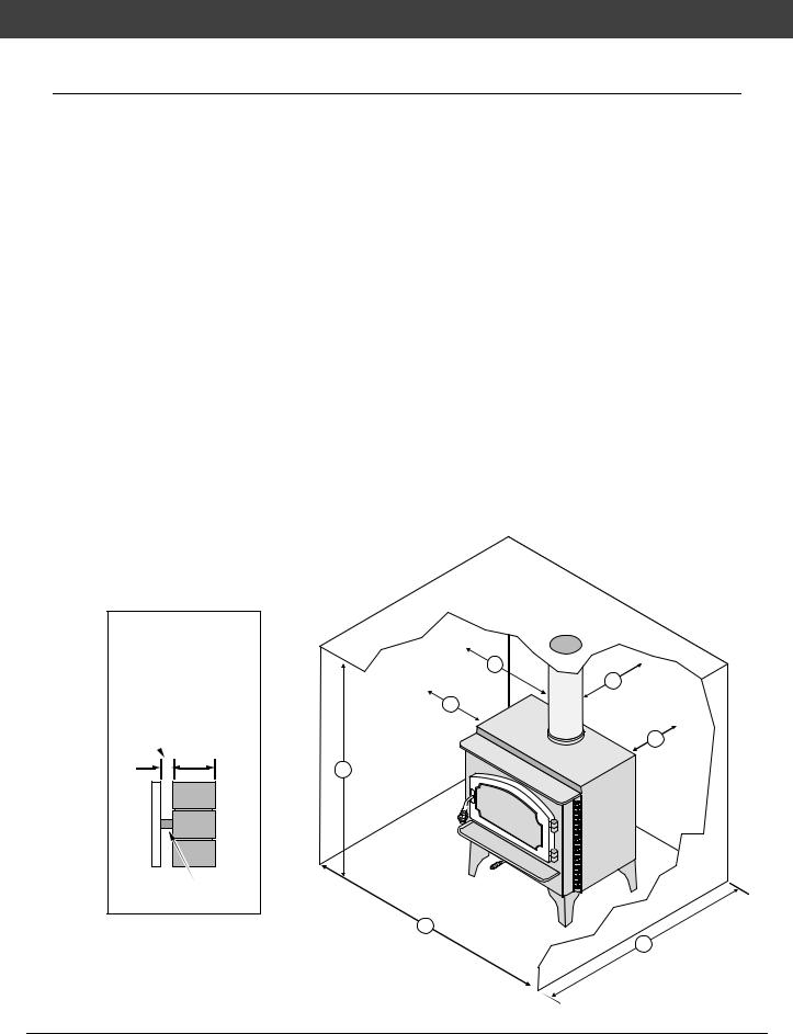
Alcove Installation Requirements
Whenever the stove is placed in a location where the ceiling height is less than 7' tall, it is considered an alcove installation. Because of the reduced height, the special installation requirements listed below must be met.
•Chimney connector and chimney must be one of the following types:
• DURAVENT model DVL with DURATEC chimney |
• GSW Double Wall Chimney Connector with Super Chimney Twenty-One |
• DURAVENT model DVL with DURA-PLUS chimney |
• SELKIRK METALBESTOS model DS connector with model SSII chimney |
• AMERI-TEC model DCC with model HS chimney |
• I.C.C. Excel (2100-2 Can.) (103-HT USA) chimney with HP connector |
• SECURITY model DL with SECURITY model ASHT or S2100 chimney |
• Standard Masonry Chimney with any one of the above listed connectors |
• METAL-FAB model DW with TG chimney |
|
Minimum |
Clearance |
Combustible |
Non-Combustible |
|
(See |
the |
illustration below) |
Alcove |
Alcove |
A |
Sidewall to stove |
13" |
6" |
|
B |
Backwall to stove |
9" |
2" |
|
D |
Connector to sidewall |
21 1/2" |
14 1/2" |
|
E |
Connector to backwall |
11 1/2" |
4 1/2" |
|
G |
Maximum depth of alcove |
48" |
48" |
|
H |
Minimum width of alcove |
49 5/8" |
35 5/8" |
|
J |
Minimum height of alcove |
84" |
6" above stove top |
|
• Alcoves are classified as combustible or non-combustible. Non-combustible alcoves must have walls and a ceiling that are 3 1/2" thick of a non-combustible material (brick, stone, or concrete). This non-combustible material must be spaced and ventilated at least 1" off of all combustible materials (walls, ceiling, etc.) to allow air to move around the non-combustible walls and ceiling. All other alcoves are considered combustible. The clearances below must be met:
Non-combustible alcove construction (on walls and ceiling) - see the explanation above.
|
d |
|
e |
Ventilated |
a |
air space |
|
3 1/2" thick non- |
|
combustible |
b |
material |
|
1" Min. |
j |
|
|
Combustible materials |
|
Non-combustible reinforcer
h
g
Travis Industries |
93508131 |
4 020327 |
Stove Installation (for qualified installers only) |
13 |
Mobile Home Requirements
•Outside air must be installed - see "Outside Air Requirements" on page Error! Reference
source not found.11
•Chimney connector and chimney must be one of the following types:
• DURAVENT model DVL with DURATEC chimney |
• GSW Double Wall Chimney Connector with Super Chimney Twenty-One |
• DURAVENT model DVL with DURA-PLUS chimney |
• SELKIRK METALBESTOS model DS connector with model SSII chimney |
• AMERI-TEC model DCC with model HS chimney |
• I.C.C. Excel (2100-2 Can.) (103-HT USA) chimney with HP connector |
• SECURITY model DL with SECURITY model ASHT or S2100 chimney |
• Standard Masonry Chimney with any one of the above listed connectors |
• METAL-FAB model DW with TG chimney |
|
NOTE: Reduced clearance connectors may not connect to the flue collar – order an appliance adapter for the connector being used.
•Stove placement must maintain the following clearances to combustibles (drywall, furniture, etc.)
Minimum |
Clearance |
Reduced Clearance |
|
(See |
the |
illustration below) |
Connector |
A |
Sidewall to stove |
13" |
|
B |
Backwall to stove |
9" |
|
C |
Cornerwall to stove |
7 1/2" |
|
D |
Connector to sidewall |
21 1/2" |
|
E |
Connector to backwall |
11 1/2" |
|
F |
Connector to cornerwall |
16 1/2" |
|
|
Corner Installations |
Straight Installations |
|
d |
|
e |
f |
a |
|
b |
c |
|
NOTE:
Measure clearances to the stove top.
•If using offsets, use the connector clearance listed to the right, not the connector manufacturer's clearance.
•The appliance must be secured to the floor (consult your building official). Secure the outside air boot to the floor and stove to insure the stove does not dislocate.
•Mobile home installations require a spark arrester at the chimney termination.
•The appliance must be grounded to the chassis of the mobile home (consult your building official).
WARNING: DO NOT INSTALL IN SLEEPING ROOM.
CAUTION: THE STRUCTURAL INTEGRITY OF THE MOBILE HOME FLOOR, WALL, AND CEILING/ROOF MUST BE MAINTAINED.
12” Min.
Connector Clearance (as outlined above)
Stove Clearance (as outlined
Travis Industries |
93508131 |
4 020327 |
14 Stove Installation (for qualified installers only)
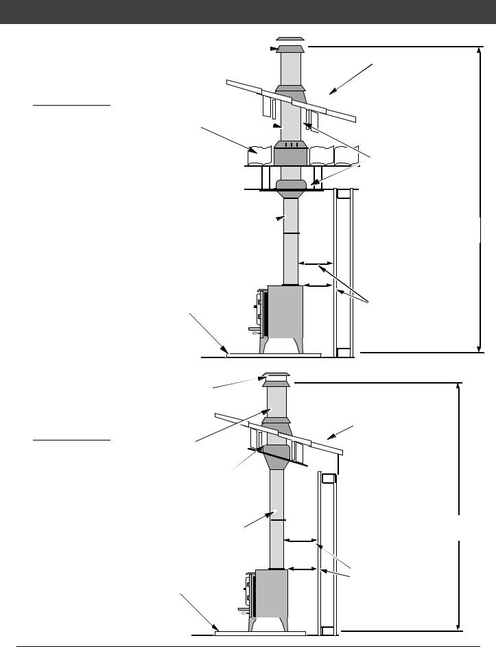
S tandard Ceiling with a Factory Built Chimney
Cathedral Ceiling with a Factory Built Chimney
Chimney Cap 

 (See the section "Chimney
Termination Requirements" for more
Chimney Sections |
} |
} |
|
||
Follow the chimney |
|
|
|
|
|
manufacturer's instructions |
|
|
and clearances for floor |
|
|
penetrations. A ceiling |
|
|
support is required, an attic |
|
|
insulation shield is required |
|
|
where insulation is present. |
|
|
Chimney Connector Sections |
|
|
Floor Protection
(See the section "Floor Protection Requirements" for more details)
Chimney Cap |
|
(See the section "Chimney |
|
Termination Requirements" |
} |
for more details) |
|
Chimney Sections |
|
Minimum Air Space to |
|
Combustibles (See Chimney |
|
Manufacturer's Instructions - |
|
usually 2") |
|
Chimney |
|
Connector |
|
Floor Protection |
|
(See the section "Floor |
|
Protection Requirements" |
|
for more details) |
|
Follow the chimney manufacturer's instructions and clearances for roof penetrations. A storm collar and flashing are required (some require a radiation shield).
Minimum Air Space to
Combustibles (See
Chimney Manufacturer's
Instructions - usually 2")
Minimum 15'
Maximum 33'
Stove Clearances (See the section "Stove
Placement Requirements" for more details)
Follow the chimney manufacturer's instructions and clearances for roof penetrations. A storm collar, flashing, and cathedral-style chimney support are required
(some require a radiation shield).
Minimum 15'
Maximum 33'
Stove Clearances (See the section "Stove
Placement Requirements" for more details)
Travis Industries |
93508131 |
4 020327 |
 Loading...