

Page 1

INSTALLATION & OPERATION
MANUAL
SP717 REV. A
Modulated Carrier Amplifier
DOC#: MN-717-A
Page 2

Sponsler, Inc.
SP717 Modulated Carrier Amplifier
pg
2
DOC#” MN-717-A
Temperature:
Input Voltage:
6-28 VDC; 100mA max.
Frequency 0-3500 Hz with 50 KHz carrier
Features:
Individual LED indicators for power and signal output
FM Approved, CSA Certified
Weight 1.7 lbs.
SPECIFICATIONS
Operating -40 to 85°C
Storage -65 to 125°C
Protected against polarity reversal
Signal Input:
(requires Pickup Coil 1-1.3 mh)
Signal Output:
Enclosure:
The SP717 Modulated Carrier Amplifier is a meter mounted device designed to produce a
carrier frequency in conjunction with an RF pickup coil, detect the shift in the carrier frequency
(modulation) that occurs with the passage of magnetic material and generate a squarewave
output pulse with each shift in the carrier frequency. The amplitude of the output pulse is
equivalent to the input supply voltage of the SP717.
The modulated carrier principle introduces no drag on the passing magnetic device, therefore,
when incorporated with a turbine flowmeter, extension of the flowmeter’s nominal linear range
at the low end is realized. This parameter is particularly useful when measuring a low mass gas
at the low end of the flowmeter’s flowrate spectrum.
LED’s are provided to indicate the presence of the input supply voltage and the output pulse.
6-28 VDC squarewave proportional to input voltage
Minimum load 1K
Short circuit protection
Mounts directly on flowmeter
Class I Groups B, C, D
Class II Groups E, F, G
Page 3

Sponsler, Inc.
SP717 Modulated Carrier Amplifier
pg
3
DOC#” MN-717-A
A)
Connect RF pickup coil to J1-1,2
B)
Connect power supply positive & negative leads to J1-3,5 respectively
C)
Connect oscilloscope positive & negative leads to J1-1,2 respectively
D)
Install jumper @ JU1
displays a 50khz + 5Khz carrier sinewave
F)
Observe carrier amplitude of 6Vp-p nominal
G)
Connect oscilloscope positive & negative leads to J1-4,5 respectively
Connect frequency generator positive & negative leads to J1-1,2 respectively.
Set function to squarewave, amplitude to 5Vp-p & frequency to 1-3500 Hz.
I)
LED D2 illuminates & the oscilloscope displays a squarewave whose
potential.
Observing oscilloscope display momentarily short pins J1-4 & 5 together. The
squarewave.
BENCH TEST CALIBRATION PROCEDURE
Required Equipment: Power Supply 6-28 VDC, Frequency Generator, Frequency Counter,
Oscilloscope
Test Procedure:
Turn power supply “ON”, observe LED D1 illuminates and oscilloscope
E)
H)
frequency is that of step H with a positive amplitude .6V < power supply
positive potential and a negative amplitude .6V > power supply negative
J)
oscilloscope will display a squarewave with an amplitude of .6V or less.
When the short is removed the oscilloscope will display a normal amplitude
Page 4
Sponsler, Inc.
SP717 Modulated Carrier Amplifier
pg
4
DOC#” MN-717-A
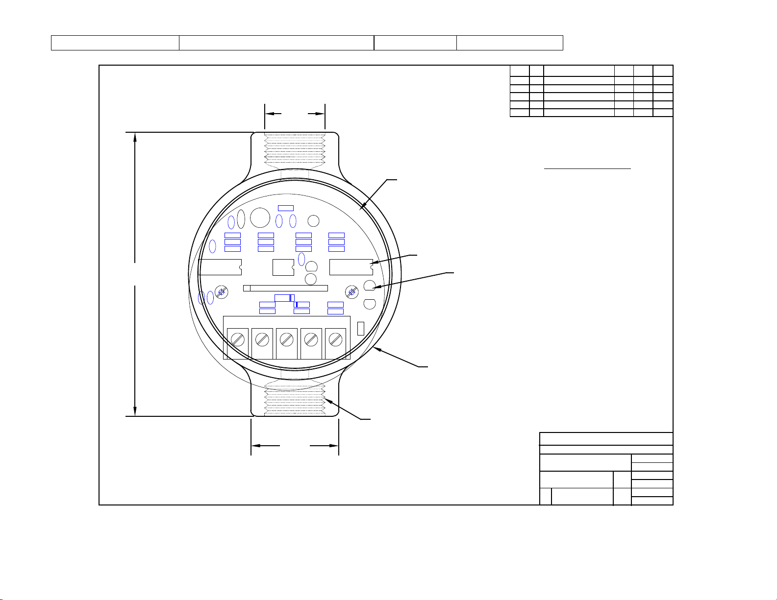
SP717 REV A
JU1
C1
C2
R16
R15
R1-6
CR2
R17
CR1
R20
R21
D2
D1
Q5-8
+
C11
A1
Q1-4
A4
C8
+
+
C10
R22
R19
R18
R13
R24
R23
R14
R12
R11
C3
R7
R8
R10
+
C6
C5
+
C4
C7C9R9
234
5
J1-1
12345
3.00 DIA.
2.40 DP.
3.75 DIA.
5.60
1.40
3/4-14 FNPT
5-5-97
TN
EM SP717
SP717 AMPLIFIER
\ELECT\SP717BD.DW
NONE
DRAWING NUMBER
MATERIAL
SPONSLER, INC.
SCALE
DRAWN BY
DATE
APPR. BY
DATE
REVIEWED BY
DATE
DESCRIPTION
REV. #
FILE NAME
COD
REVCKDR
AUTH
REVISION RECORD
DATE
DC INPUT -
SIGNAL OUT +
DC INPUT +
SIGNAL IN -
SIGNAL IN +
5
4
3
2
1
TERMINAL LOCATION
POWER INDICATOR
OUTPUT SIGNAL INDICATOR LED
(JUMPER JU1 INSTALLED)
NOTE: DIMIENSIONS ARE IN INCHES
.90
©2009
Pub. No. MN-714-A
(09/09)
 Loading...