

Page 1

Page 2

TABLE OF CONTENTS
APPLICATION .............................................................................................................................................1
FEATURES ..................................................................................................................................................1
DESCRIPTION.............................................................................................................................................1
WORKSHEET ..............................................................................................................................................2
SETTING PRESET A...................................................................................................................................3
SETTING PRESET B...................................................................................................................................3
SETTING THE COUNTER...........................................................................................................................3
SETTING THE RATEMETER ......................................................................................................................4
SETTING LOCKOUT CODE........................................................................................................................4
SETTING THE COM. OUTCARD ................................................................................................................5
SETTING RATE OR COUNT FOR ANALOG OUTPUT ..............................................................................6
SETTING OUTPUT PULSE FREQUENCY .................................................................................................6
SETTING RELAY FUNCTION & ON TIMES ...............................................................................................7
VIEWING RATE, BATCH TOTAL, GRAND TOTAL.....................................................................................7
SETTING 16-POINT K-FACTOR .................................................................................................................8
SPECIFICATIONS .......................................................................................................................................9
TERMINATION ............................................................................................................................................9
OPERATIONS............................................................................................................................................10
K-FACTOR.................................................................................................................................................10
COUNTER .................................................................................................................................................10
APPLICATION ...........................................................................................................................................11
MOUNTING DIMENSIONS........................................................................................................................11
PULSE INPUTS .........................................................................................................................................11
ANALOG INPUTS ......................................................................................................................................11
SETTING K FACTOR FOR ANALOG INPUT ............................................................................................12
ANALOG INPUT EXCHANGE/CALIBRATION ..........................................................................................12
RESET .......................................................................................................................................................12
FACTOR/"DATALOST"/"RFFF" .................................................................................................................12
PRESETS ..................................................................................................................................................13
RELAY OUTPUT TIMING ..........................................................................................................................13
SCALED OUTPUT/DATALOST .................................................................................................................13
RATEMETER .............................................................................................................................................13
TING RATE K-FACTOR FOR PULSE INPUT ...........................................................................................13
LOCKOUT..................................................................................................................................................14
REMOVING THE CASE.............................................................................................................................14
INPUT CARD MODIFICATION ..................................................................................................................14
OUTCARD RS232/RS422 SERIAL INTERFACE ......................................................................................14
RS232 ELECTRICAL REQUIREMENTS ...................................................................................................14
RS422 ELECTRICAL REQUIREMENTS ...................................................................................................15
RS232/RS422 SERIAL INPUT CODES.....................................................................................................15
SERIAL INTERFACE OPERATION...........................................................................................................15
STROBE ADDRESS OPERATION............................................................................................................16
STROBE INPUT ELECTRICAL REQUIREMENTS ...................................................................................16
232 WIRING...............................................................................................................................................16
STROBE WIRING FOR RS232 .................................................................................................................16
RS422 INPUT WIRING ..............................................................................................................................17
STROBE WIRING FOR RS422 .................................................................................................................17
ANALOG OUTPUT ....................................................................................................................................17
OPTIONAL 16-POINT LINEARIZATION OF VARIABLE K-FACTOR........................................................17
WIRING ILLUSTRATION............................................................................................................................20
Page 3
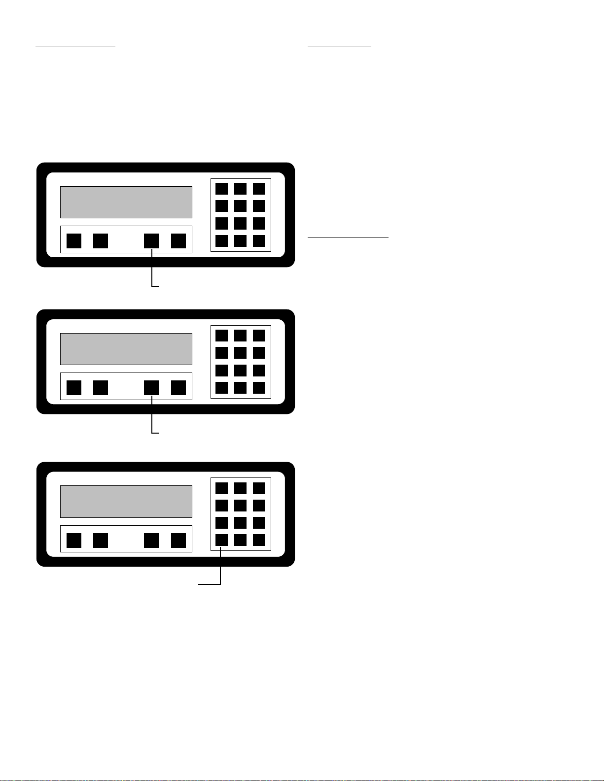
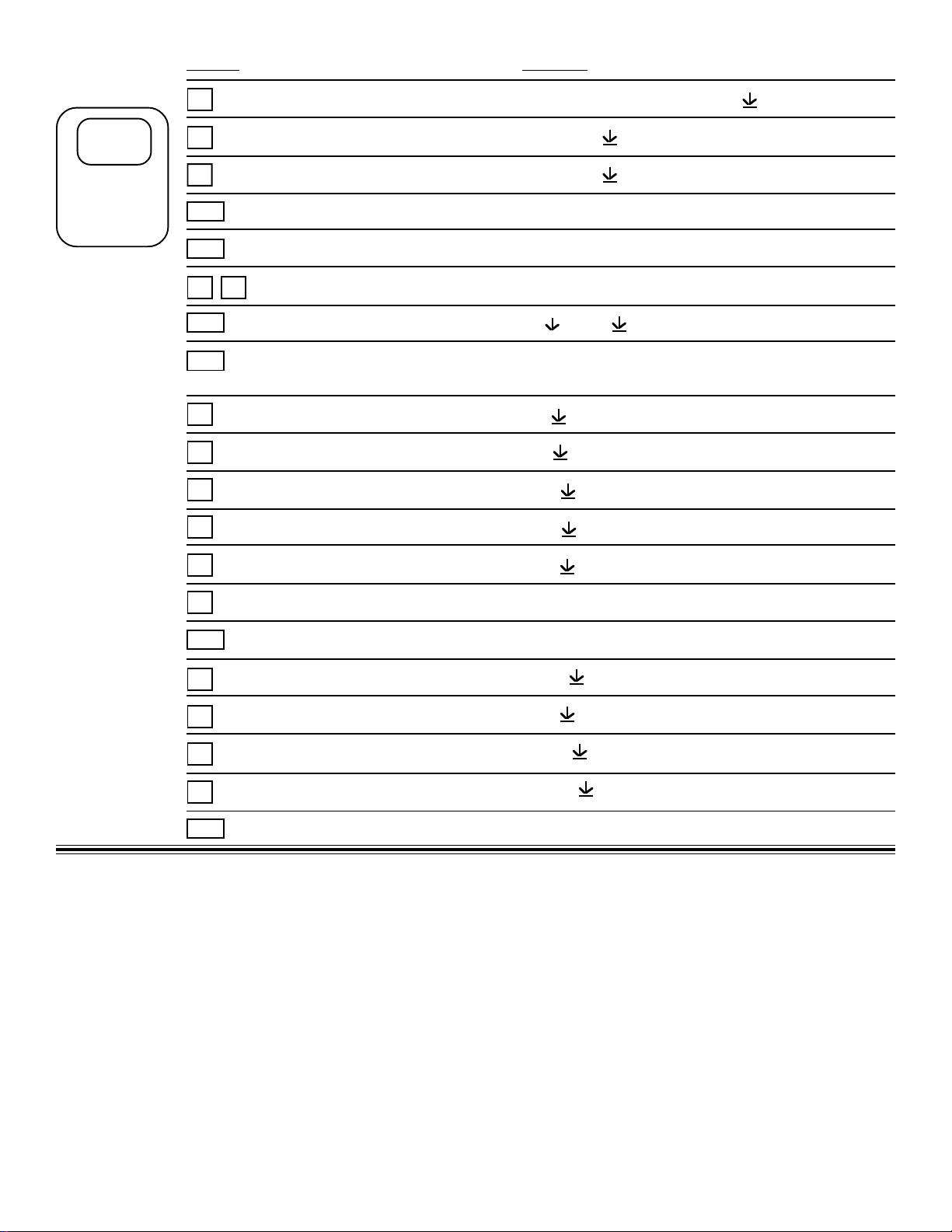
APPLICATION
Batch control, cut to length, packaging, blending. The
display may be toggled between total, rate, and grand total.
Programmable K-factor makes keying - in engineering units
easy. Unit accepts pulse, contact closures or analog input
and provides two separate preset controls.
1 2 3
54 6
FEATURES
* Pulse or Analog Input (with Totalizing
Integration)
* Display Total, Rate or Grand Total
* 2 Presets - User Selectable for Total, Rate or
Grand Total
* Pulse Input to 20 KHz Count Frequency
* 16 Point Linearization
* K - Factor Programmable to 8 Places
* Security Lockout
* 2 way RS232/422/422M Communications
* NEMA 4X Front Panel
* Scaleable 4 - 20mA Output of Rate
* Scaled Pulse Out, Frequency Selectable
PRE A PRE B RATE/T OT AL MENU
AB CD
PRESS "C" TO SEE RATE
PRE A PRE B RATE/T OT AL MENU
AB CD
PRESS "C" AGAIN TO SEE
BATCH TOTAL.
PRE A PRE B RATE/T OT AL MENU
AB CD
PRESS "ENT" TO SEE
GRAND TOTAL
87 9
ENT CLR
0
1 2 3
54 6
87 9
ENT CLR
0
1 2 3
54 6
87 9
ENT CLR
0
DESCRIPTION
Featuring 8 digits of bright, .55”, alphanumeric display, the
pulse input version of the unit can accept up to 20,000
pulses per second. The analog input version accepts
inputs, such as 4 to 20mA or 1 to 5V. It uses a highly linear
integrator (V to F converter) to generate 0 to 10KHz digital
pulses. The unit has two separate, 8 digit, floating decimal,
“K” factors to convert the inputs to meaningful count and
rate data. The user, with the push of a button, can toggle
back and forth to view the total of the batch, the rate of flow
and the grand total count.
Two controls outputs can be assigned independently by the
user to activate at preset batch count, rate or grand total for
.1 to 9.9 seconds or until reset externally.
A scaled pulse output is also provided by an open collector
driver. Since the output frequency is user selectable at 10,
200, 2K or 20KHz, the unit can transmit the count data to
electromechanical or electronic counters as well as computers, programmable controllers or other monitor equipment.
An optional analog 4 to 20mA output, selectable between
rate or total, allows the user to select 4mA and 20mA rate
settings to control strip chart recorders or other peripherals.
Up to 15 units can be connected to optional RS232 or
RS422 communications port to set control points or access
data. With RS422M up to 256 units can be linked together
and addressed separately to transmit unit states or accept
new set points. The Baud rate is “Auto Ranging” from 300
to 19.2K. It is also OPTOMUX Compatible.
1
Page 4
PRE A PRE B RATE/TOT AL MENU
AB CD
1 2 3
54 6
87 9
ENT CLR
0
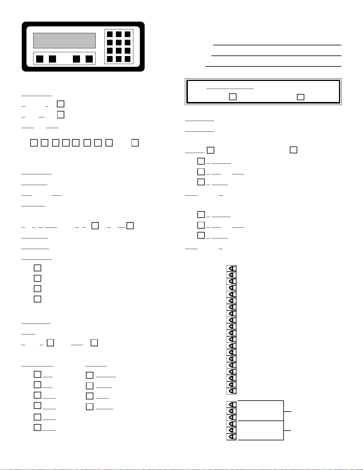
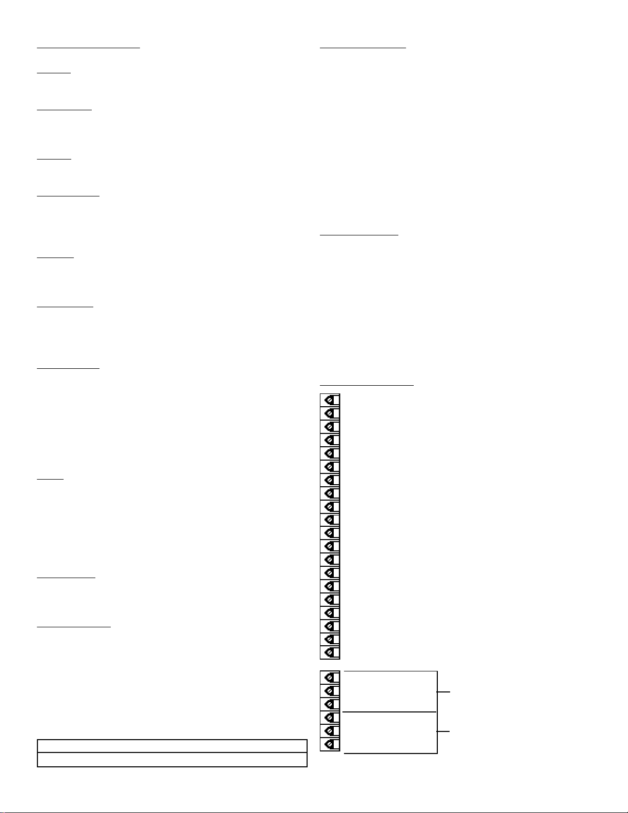
WORKSHEET
MODEL #
SERIAL #
UNIT #
COUNTER
K-FACTOR __ __ __ __ __ __ __ __
Reset to 0
Set to Preset
DECimal LOCation (0-8)
876543210
none
RATEMETER
K-FACTOR __ __ __ __ __ __ __ __
WINDOW (02-24) __ __
SIGnificant FIGures (1-6) __ __
WEIGHT (00-99) __ __
AnaLoG OUTput RaTe CouNT
SET LOW rate 4mA __ __ __ __ __ __ __ __
SET HIGH rate 20mA __ __ __ __ __ __ __ __
LOCKOUT CODE __ __ __ __
PR-LCK PR-UNLK
PRESET A __ __ __ __ __ __ __ __
PRESET B __ __ __ __ __ __ __ __
RELAY Open Collector
A TOTAL
A GRand TOTal
A RATE
DURation of A (0.0-9.9) __ . __
B TOTAL
B GRand TOTal
B RATE
DURation of B (0.0-9.9) __ . __
OUT FREQuency
20000
2000
200
10
OUTCARD
UNIT (00-15) __ __
ParalleL or SERial
(RS422M)
BAUDRATE PARITY
300 SPACE
600 EVEN
1200 ODD
2400 MARK
4800
9600
1- NOT USED
2- SCALED OUTPUT O.C.
3- ANALOG OUTPUT (SINK)
4- INPUT A (PULSE/ANALOG)
5- RESET INPUT
6- NOT USED
7- NOT USED
8- NOT USED
9- NOT USED
10- NOT USED
11- GROUND (-DC)
12- GROUND (-DC) INPUT COMMON
13- +12 VDC OUT
14- +DC POWER IN
15- ISOLATED -12VDC
16- ISOLATED +12VDC
17- AC IN
18- AC IN
19- PRESET B OPEN COLLECTOR
20- PRESET A OPEN COLLECTOR
R1- N.O
R2- N.C. A
R3- COMMON
R4- N.O
R5- N.C. B
R6- COMMON
2
Page 5
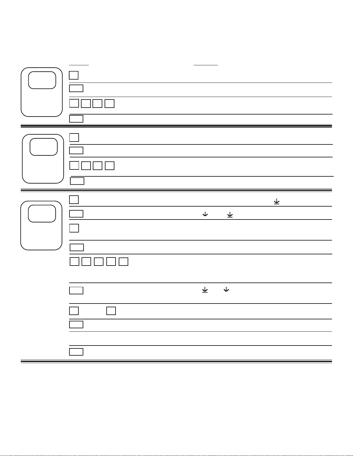
STEP
1
SETTING
PRESET A
SETUP PROCEDURE
NOTE: Start here and finish to the end. If you make a mistake, press
ENT until you reach the beginning.
PRESS DISPLAY
A
CLR
1
(SAMPLE PRESET)
ENT
(FINAL PRESET) THEN FLASHING PRESET #
2 3 4
PRESET A
0 FLASHES
1 2 3 4 PRESET FLASHES
1 2 3 4 IS ENTERED
STEP
2
SETTING
PRESET B
STEP
3
SETTING
THE
COUNTER
B
CLR
1
(SAMPLE PREWARN)
ENT
D
ENT
D
CLR
(PRESS D FOR DECIMAL POINT)
K FACTOR IS DIVIDER. IT CONVERTS INPUT TO ENGINEERING UNITS.
ENT
(PREWARN) THEN FLASHING PRESET #
2 0 0
(SET UP COUNTER) K FACTOR FLASHES; THEN SHOWS
1
2
D
(K FACTOR ENTERED) R0 SP (RESET TO 0 "ADD" OR SET TO
8
7
PRESET B
0 FLASHES
1 2 0 0 PRESET FLASHES
1 2 0 0 IS ENTERED
MENU FLASHES TO DEV TYP
RT CNT (RATE OR COUNT)
CURRENT K-FACTOR
0 FLASHES
1 . 2 7 8 FLASHES
PRESET "SUBTRACT")
B
ENT
PRESS ANY NUMBER DECIMAL POINT MOVES TO THAT POSITION
ENT
OR SELECTS R0 OR SP
SELECTION ENTERED DEC LOC (DECIMAL LOCATION)
D
LAST COUNT READING
3
Page 6
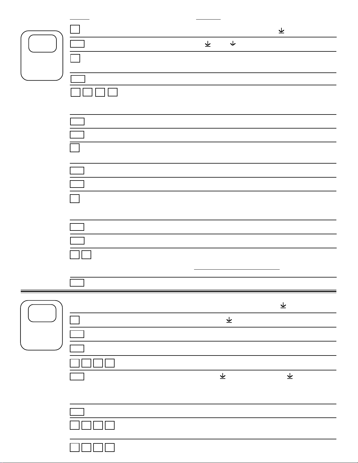
PRESS DISPLAY
STEP
4
SETTING
THE
RATEMETER
D
ENT
B
CLR
(PRESS D FOR DECIMAL POINT)
K FACTOR IS DIVIDER. IT CONVERTS INPUT TO ENGINEERING UNITS.
ENT
CLR
5
(EXTENDS THE SAMPLING WINDOW TO 5 SECONDS)
ENT
CLR
(SET UP RATEMETER) K FACTOR FLASHES; THEN SHOWS
1
D
7
(K FACTOR ENTERED) WINDOW ##
(AS AN EXAMPLE) WINDOW 05
(WINDOW ENTERED) SIG FIG ##
8
MENU FLASHES TO DEV TYP
RT CNT (RATE OR COUNT)
CURRENT K-FACTOR
0 FLASHES
1 7 . 8 FLASHES
WINDOW 00
SIG FIG 00
STEP
5
SETTING
LOCKOUT
CODE
6
(SIG FIG INDICATES HOW MANY MEANINGFUL DIGITS ARE SHOWN
TRAILING ZEROS ARE INSERTED IF NECESSARY)
ENT
CLR
WEIGHT IS AN AVERAGING FACTOR. HIGHER SETTINGS PROVIDE MORE AVERAGING, FOR A
MORE STABLE DISPLAY. DERIVED FROM:
ENT
D
ENT
CLR
1
(AS AN EXAMPLE) SIG FIG 06
(SIG FIG ENTERED) WEIGHT #.#
WEIGHT 0.0
99
(AS AN EXAMPLE) WEIGHT 9.9
(OLD DATA x "WEIGHT" + NEW DATA)
(WEIGHT ENTERED) LAST COUNT READING
MENU FLASHES TO DEV TYP
LOCKOUT
(LOCKOUT SELECTED) CODE FLASHES; THEN SHOWS OLD CODE #.
0 FLASHES
(AS AN EXAMPLE) 1 1 1 1 FLASHES
1 1 1
("WEIGHT" + 1)
ENT
ENT
1
1
(CODE ENTERED) PR LCK PR UNLK
(LOCKOUT OF (LOCKOUT OF ALL FRONT
FRONT PANEL) BUTTONS EXCEPT
PRESETS A, B AND CLR)
(LOCKOUT SELECTION ENTERED) LAST COUNT READING
1 1 1
1 1 1
4
LOCK ON FLASHES
(APPROPRIATE PANEL CHANGES LOCKED OUT)
LOCK OFF FLASHES
(PANEL CHANGES ALLOWED)
Page 7
PRESS DISPLAY
STEP
6
SETTING
THE COM.
OUT CARD
SKIP IF NOT
USED
D
D
D
ENT
CLR
1 2
ENT
ENT
D
D
D
D
MENU FLASHES TO DEV TYP
LOCKOUT
OUTCARD
(OUTCARD SELECTED) UNIT ##
UNIT 00
(AS AN EXAMPLE) UNIT 12
(UNIT LABELED 12) PL SER *
BAUDRATE FLASHES THEN LAST
BAUDRATE USED.
300
600
1200
2400
D
D
ENT
D
D
D
D
ENT
4800
9600 (PRESS D TO GO BACK TO 300)
(PRESS AS DESIRED) PARITY FLASHES THEN LAST PARITY SELECTED
EVEN
ODD
MARK
SPACE (PRESS D TO GO BACK TO EVEN)
(PRESS AS DESIRED) LAST COUNT READING
* UNIT ALWAYS SHOULD BE SER. PL IS DISABLED
5
Page 8

PRESS DISPLAY
STEP
7
SETTING
RATE OR
COUNT FOR
ANALOG
OUTPUT
SKIP IF NOT
USED
D
D
D
D
ENT
D
ENT
CLR
1 2
(PRESS D FOR DECIMAL POINT)
AS AN EXAMPLE (IN THIS CASE 125.5 = 4mA)
ENT
(ANALOG SETUP SELECTED) ANLG RT (4-20mA OUTPUT FOR RATE)
(PRESS D TO TOGGLE ANLG CT (4-20mA OUTPUT FOR COUNT)
BETWEEN SELECTIONS)
(ANLG RT OR ANLG CT SELECTED) SET LOW FLASHES THEN CURRENT
5
(LOW SET AT 125.5) SET HIGH FLASHES THEN CURRENT HIGH
5
D
MENU FLASHES TO DEV TYP
LOCKOUT
OUTCARD
ALG OUT
LOW SETTING
0 FLASHES
1 2 5 . 5 FLASHES
SETTING
STEP
8
SETTING
OUTPUT
PULSE
FREQUENCY
CLR
1 5
(PRESS D FOR DECIMAL POINT)
AS AN EXAMPLE (IN THIS CASE 150.7 = 20 mA)
ENT
D
D
D
D
D
ENT
D
D
0
(HIGH SET AT 150.7) LAST COUNT READING
(OUT FREQUENCY SELECTED) 2000 (DISPLAYS LAST SELECTION)
7
D
0 FLASHES
1 5 0 . 7 FLASHES
MENU FLASHES TO DEV TYP
LOCKOUT
OUTCARD
ALG OUT
OUT FREQ
200
10
D
ENT
20000 (PRESS D TO GO TO 2000)
(PRESS AS DESIRED) LAST COUNT READING
6
Page 9

PRESS DISPLAY
STEP
9
SETTING
RELAY
FUNCTION
AND
ON TIMES
D
D
D
D
D
D
ENT
D
D
ENT
CLR
1
MENU FLASHES TO DEV TYP
LOCKOUT
OUTCARD
ALG OUT
OUT FREQ
RELAY
(RELAY SELECTED) A GR TOTAL (RELAY A SET TO GRAND TOTAL)
A RATE (IF RATE SELECTED, DURATION
IS DISABLED)
A TOTAL (RELAY A SET TO TOTAL)
(PRESS AS DESIRED) DUR A #.#
DUR A 0.0
(AS AN EXAMPLE) DUR A 1.2 (RELAY ACTIVATES FOR 1.2 SEC.)
2
VIEWING
RATE,
BATCH
TOTAL,
GRAND
TOTAL
ENT
D
D
ENT
CLR
5
ENT
C
C
ENT
ENT
(ON TIME ENTERED) B RATE (IF RATE SELECTED, DURATION
IS DISABLED)
B TOTAL (RELAY B SET TO TOTAL)
B GR TOTAL (RELAY B SET TO GRAND TOTAL)
(PRESS AS DESIRED) DUR B #.#
DUR B 0.0
(AS AN EXAMPLE) DUR B 5.5 (RELAY ACTIVATES FOR 5.5 SEC.)
5
(ON TIME ENTERED) LAST COUNT READING
R ###### (RATE READING)
######## (BATCH TOTAL)
PRESS C TO GO BACK TO RATE AGAIN
GR TOTAL FLASHES THEN THE GRAND TOTAL
VALUE FLASHES
######## (BATCH TOTAL)
PRESS C TO GO BACK TO RATE AGAIN
PRESS ENT TO GO BACK TO GRAND TOTAL
7
Page 10

PRESS DISPLAY
SETTING
16 POINT
K-FACTOR
16 POINT
ONLY
APPEARS
ON UNITS
WITH
16 POINT
OPTION
NOTE: If TEST
is entered, point
data can be
entered exactly
as in selected
time entries.
However, when
the unit "runs"
in Test Mode
"K-factor is
always 1.
"Rate" (R)
displays
frequency
(inputs per
second).
Counter displays 1 count
per each input.
NOTE: "BAD
SEQ" will
appear if
frquencies are
not in ascending order with
point numbers.
After 2 seconds, the first
point number
with error will
appear so data
can be viewed
and corrected.
D
D
D
D
D
D
D
ENT
D
D
D
ENT
1
ENT
CLR
1 0 0
ENT
CLR
1 0 0
ENT
CLR
ENT
MENU FLASHES TO DEV TYP
LOCKOUT
OUTCARD
ALG OUT
OUT FREQ
RELAY
16 POINT
(16 POINT SELECTED) MINUTES
HOURS
TEST
SECONDS (PRESS D TO GO TO MINUTES)
(PRESS AS DESIRED) POINT 00 (ENTER POINT 00 TO GO TO RUN
MODE)
(SELECT POINT 1) POINT 01 (KEY IN POINT DESIRED)
F ## (SHOWS FREQUENCY IN MEMORY)
F 0
(AS AN EXAMPLE) F 100 (FREQUENCY FOR POINT 1 IS 100)
K ## (SHOWS K-FACTOR IN MEMORY)
K 0
(AS AN EXAMPLE) 100 (K-FACTOR FOR POINT 1 IS 100)
POINT 02 (ENTER POINT DATA AS DESIRED)
POINT 00 (ENTER POINT 00 TO EXIT SETUP)
LAST COUNT READING
8
Page 11
SPECIFICATIONS
Display
8 Digit, .55” Segment, Red Orange, LED.
Input Power
A: 110 VAC ±15% or 12 to 27 VDC
B: 220 VAC ±15% or 12 to 27 VDC
Current
Maximum 280 mA DC or 5.3 VA at rated AC voltage.
Output Power
(On AC powered units only): +12 VDC at 100mA. Separate
isolated 12 VDC at 100mA to allow +12 VDC or +12 VDC
regulated ±5% worst case.
Memory
EEPROM stores all program and count data for minimum of
10 years if power is lost.
Pulse Inputs
Standard, High impedance pulse input. Open or 0 to 1 VDC
(low) 3 to 30 VDC (high) 10K Ohm impedance 20 KHz max.
input speed (min. on/off 25 usec.).
Control Outputs
(Each of two outputs)
1) NPN Transistor Version: (Optional)
Open collector sinks max. 250mA from 30
VDC when active. (When relay is used, 10
VDC is provided at transistor outputs through
relay coil. If greater than 2mA is used, relay
will remain energized. Applying greater than
10 VDC may destroy unit. Transistor will sink
100mA in “ON” state).
2.) SPDT Relay Version:
10A 120/240 VAC or 28 VDC (Standard)
Analog Output
Digital or analog inputs (except square law) can be ordered
with a 4mA to 20mA output of the rate or total reading.
User keys in the 4mA and 20mA settings at set-up. A
sinking driver generates a corresponding linear current
through the external devices, updating with each update of
the rate or total. Accuracy is ±100 uA worst case. Compliance voltage must be 3 to 24 VDC, non-inductive. (The
unit can provide the DC source as long as the drop across
any device being driven does not exceed 21 V).
Analog Inputs
The current loop or voltage input is converted to a highly
linear 0 to 10KHz frequency. This frequency can then be
scaled by the 8 digit K - Factors to count or display rate in
separate engineering units.
Accuracy over full temperature range:
Zero error: ±0.175% full scale max.
Overall error: ±0.5% full scale max.
Reset
Front push button: “CLR” resets displayed number and
control output.
Remote: 3 to 30 VDC positive edge resets batch counter
and control output.
Impedance: 10K to ground (-DC)
Minimum pulse: 5 msec
Temperature
Operating: +32ºF (0ºC) to +130ºF (+54ºC)
Storage: -40ºF (-40ºC) to+200ºF (+93ºC)
Factored Output
The unit gives one pulse out for each factored count. Open
collector sinks 30 VDC maximum to 1 volt maximum at
100mA maximum. Output speed is user selectable (see
Table below). An internal buffer holds up to 10,000 pulses
for output at the selected frequency before “DATALOST”
flashes, indicating pulses are lost. If factored rate exceeds
7 digits, “RFF...” flashes. These alarms indicated that
speed has been exceeded.
Speed (Hz) 10 200 2000 20000
Min. on/off (msec) 47.5 2.0 0.2 0.013
TERMINATIONS
1- NOT USED
2- SCALED OUTPUT O.C.
3- ANALOG OUTPUT (SINK)
4- INPUT A (PULSE/ANALOG)
5- RESET INPUT
6- NOT USED
7- NOT USED
8- NOT USED
9- NOT USED
10- NOT USED
11- GROUND (-DC)
12- GROUND (-DC) INPUT COMMON
13- +12 VDC OUT
14- +DC POWER IN
15- ISOLATED -12VDC
16- ISOLATED +12VDC
17- AC IN
18- AC IN
19- PRESET B OPEN COLLECTOR
20- PRESET A OPEN COLLECTOR
R1- N.O
R2- N.C. A
R3- COMMON
R4- N.O
R5- N.C. B
R6- COMMON
9
Page 12

OPERATIONS
Presets
Two control presets are provided on the unit. The preset
numbers can be made to flash without interrupting the
control function by pressing “A” (Preset A) or “B” (Preset B).
Press “ENT” to return to rate or total display. Change the
preset by clearing the flashing preset number and keying in
a new number before pressing the “ENT” button. (Count
pulses may be lost if the preset is changed while pulses are
coming in.) In the “Relay Set-Up” the user selects either
one or both preset outputs to be activated the total, grand
total, or rate. If selected for total or grand total the outputs
can be set to activate the preset relay for 0.1 to 9.9 seconds or latch (0.0 setting) until reset. If selected for rate
control, the rate will be compared with the preset at each
display update and the output activated if the rate is equal
or grater than the preset. The output drops out again only if
the rate drops below the preset. If the rate goes out of
scale, the display will show all “F” and the output will
remain in the state prior to going out of scale.
Outcard
RS232 or RS422 serial two way communication options are
available. Up to 15 units can be linked together and
addressed separately to transmit unit status or accept new
set points in the standard ASCII format. Baud rates of 300,
600, 1200, 2400, 4800 or 9600 as well as choice of odd,
even, space or mark parity can be selected by keypad
control.
OPTION 1: RS232 Serial Interface
OPTION 2: RS422 Serial Interface
OPTION 5: RS422M Serial Interface
Lockout
Unauthorized front panel changes can be prevented by
entering a user selected 4-digit code, in the “LOCKOUT”
mode. A (2) level “LOCKOUT” offers the user the option to
“LOCKOUT” all front panel changes or “LOCKOUT” all but
preset A, B, and CLR. The status of the unit can be
observed but, “LOCK ON” appears if changes are attempted. Entering the code returns the unit to “LOCK OFF”
status.
Press the “C” button while the units is displaying the batch
to display the rate; “R” is displayed on the left side of the
display.
K-FACTOR
The K-Factor is used to convert the input pulses or frequency generated internally by the analog input to engineering units. The 8 digit K-Factor dividers, with decimal
keyed into any position, allow easy direct entry of any KFactor greater than 0.0001 to 99999999.
Separate K-Factors may be entered for the count and rate
section. Thus, you may batch and total in gallons and
display rate in liters per hour. The maximum factored count
speed is 20,000 Hz. The maximum factored rate is 7 digits.
A 16-Point Linearization variable K-factor option makes
flow systems more accurate and often extends their usable
range by allowing users to dial in different K-factors for
different flow rates. It works with either pulse input or
standard analog current loop or voltage input.
It is recommended for flow meters whose K-factors change
with different rates of flow. This option can also be used to
display static volume in irregular shaped vessels by interfacing level or pressure transducers to the analog input.
From 3 to 16 points of frequency from 0 to 10,000 Hz and
K-factors greater than .0001 to 999,999 are dialed in at set
up. The unit uses 8-digit floating math to interpolate between settings. Rate per second, per minute or per hour
programmability eliminates the need to calculate separate
K-factors for total and rate.
COUNTER
Each of the total and grand total counters have 8 digits. In
the set-up mode choose “RO” (reset to zero) for adding
operation or “SP” (set to preset) for subtracting operation.
While viewing the count, the display can be made to flash
the grand total. While flashing the grand total, CLR resets
the grand total counter.
RATEMETER
Accurate to 5 1/2 digits (±1 display digit). The rate meter
can be programmed to accept almost any number of pulses
per unit of measurement, sample from 2 to 24 seconds
maximum, and autorange up to 6 digits of significant
information. The rate meter with a “K” factor of 1 displays
the rate of pulses per second. Simply dial in the proper “K”
factor to display in minutes, hours or other units of measurement.
10
Page 13

APPLICATION
PULSE INPUTS
The unit accepts output pulses from most encoders, prox.
switches or contactors. Connect the pulse to Input A Pin 4.
The unit counts on the negative edge of a pulse: Low: 0 to
1 VDC, High: 3 to 30 VDC.
SOURCING INPUT - Has a 10K Ohm pull down resistor to
ground and must be driven high by a sourcing device such
as a PNP transistor or a contact to +DC, Pin 13.
SINKING INPUT- Has a 4.7K Ohm resistor to +12 VDC
and must be driven low by a sinking device such as a NPN
transistor or a contact to ground (Pin 12).
The unit monitors the power consumption and transmits the
rate, total or grand total usage upon command to a printer,
PLC or computer. Either control Relay A or Relay B can be
activated by rate, total or grand total readings. If Relay A is
set for rate, it can activate an alarm for load management if
the preset usage is exceeded. Relay B can be set to
activate at any rate, total or grand total alarm setting. The
customer has it his way when selecting the external devices to record the unit data. A frequency selectable pulse
output can drive any totalizer, PLC, computer or other pulse
input device from 10 to 20,000 Hz. With the analog output
option the customer keys in both the 4mA and 20mA rate
settings and the unit drives the strip chart recorder, load
shedding or other monitor devices. Finally, with the RS232/
RS422 or RS422M option the customer can have a printer
record any data or have a computer communicate with up
to 256 units to monitor the usage, change alarm points,
reset the internal counters, etc. from a remote location.
MOUNTING DIMENSION
Dimensions are in inches (mm)
7.349
(186.7)
7.055
(179.2)
ABCD
(207.5)
8.170
1 2 3
4 5 6
7 8 9
CLR0SET
3.305
(83.9)
PULSE SPEED
The Max input speed is specified by the 8th digit of the part
number based on a 50% on/off pulse. Although the unit
can accept pulses as short as 25 usec on/off if speed “E” is
selected, it is advised that only the maximum speed
needed be ordered. When lower speeds are specified,
additional filtering is added that make the inputs more
immune to electrical noise. “A” input speed should always
be used when pulsing with a switch contact to prevent
additional erratic count inputs.
INPUT SWITCH SELECTION
Inputs use an input signal conditioning board which is
plugged onto the main board just behind the display. It has
dip switches which set the debounce filtering (max. count
speed). (See section for “Removing Case” to get to the
input modules if changes on the pulse input board are
needed.)
S1, S2 determine debounce filtering and control max. input
speed,
(A) S1, S2-ON, 0-40 Hz (min. 12.5 msec on/off)
(C) S1-ON, S2-OFF, 0400 Hz (min. 1.25 msec on/off)
(E) S1, S2-OFF, 0-20K Hz (min. 25 usec on/off)
S3, S4 set the input characteristics as designated by the
5th and 6th digits of the part number.
SOURCING INPUT: S3, S4-OFF (needs sourcing input)
SINKING INPUT: S3-OFF, S4-ON (needs sinking input)
.525
(13.3)
7.365 ± .010
(187.0 ± .25)
PANEL
CUTOUT
6.000
(152.4)
2.496 ± .010
(187.0 ± .25)
2.480
(62.9)
ANALOG INPUTS
The analog input versions accept signals from transmitters
that give linear outputs. The input signal modules are
mounted just behind the display and are calibrated for the
input specified. Insure that the sensor output matches the
unit input. Connect the analog signal to input A (Pin 4) with
the return to ground (Pin 12).
SQUARE LAW: 4-20mA; 250Ω input impedance, the
square law input is a special input that compensates for
non-linear inputs. Specifically, inputs that require square
root extraction to provide accurate count and rate determinations. The input signal is converted to 0 to 10,000 pulses
per second input to the process (see Table below).
11
Page 14

4-20mA Square Law Table
mA Input Pulse/Sec mA Input Pulse/Sec
4 0000 10 6123
5 2500 12 7071
6 3535 16 8660
7 4330 18 9354
8 5000 20 10000
To calculate the Pulse/Sec for a particular input use the
following formula:
mA - 4 x 10000 = # Pulse/Sec to Processor
√
16
EXAMPLE: To calculate the Pulses/Sec for 9mA Input.
9 - 4 x 10000 = 5590 Pulses/Sec to Processor
16
√
CALCULATING THE K- FACTORS
The analog inputs are converted to a highly linear 0 to
10000 pulse per second frequency. The high level of any
analog input will generate this 10000 Hz frequency. The
pulses go directly to the central processor. The K- Factors
are used to convert the pulses into the correct units of
measurement.
Rate K- Factor: 10000/R, where R = high output rating
(20mA or 5V) of transmitter. 10000 divided by 20mA or 5V
rating of transmitter. Eg. 20mA rating of transmitter is 250
gal. per min. The rate K - Factor to key into the unit for gal.
per min. is 40 (10000 divided by 250).
If a rate is desired in a different unit of measure or a
different timebase, factor the transmitter rating to the unit of
measure and timebase desired and use the formula above.
Eg. 5V output rating of a transmitter is 300 gal. per min.
and rate desired is liters per hr. The factored rate for this
transmitter for liters per hr. is 68135.94 (300 x 3.78533 [gal.
to liters] x 60 [min. to hr.]. The rate K - Factor for liters per
hr. is 0.1467654 (10000 divided by 68135.94).
Counter K-Factor: = 10,000/R/Sec, where R = High output
rating (20mA or 5V) of transmitter factored to rate per
second. Eg. 20mA rating of transmitter is 500 gal. per min.
Rate per sec. is 8.3333333 (500 divided by 60). Counter KFactor to key into unit is 1200 (10000 divided by
8.3333333.
If a different unit of measure is desired, factor the given
transmitter rating to the desired unit of measure in units per
second and use the formula above. Eg. 5V rating of transmitter is 250 gal. per hr. and it is desired to totalize in liters.
Rate in liters per second is .2628701 (250 x 3.78533 [gal.
to liters] divided by 3600 [hr. to sec]). Counter K-Factor to
key into unit to totalize in liters from 250 gal. per hr. transmitter is: 38041.603 (10000 divided by .2628701).
ANALOG INPUT EXCHANGE/CALIBRATION
If an analog sensor cannot be obtained that matches the
unit input, it is recommended that the unit be returned to
have the analog input module exchanged and recalibrated.
Recalibration should only be attempted by someone who
has the equipment to generate a very accurate low and
high signal and who has the training to open the unit and
work with grounded equipment necessary to protect the
static sensitive CMOS circuitry.
Set the ratemeter as follows: K Factor = 1, sig. fig. = 6,
window = 02 and the weight = 0. See the section “Removing the Case” to get at the analog input card, mounted just
behind the display. There are two pots that set the “0”
(R3) and 10000 Hz (R15) frequency. R3 and R15 are
silkscreened just under the .3 inch square pots. While
inputing a very accurate high input signal. Set R15 so that
the display reads 9999 to 10000. Remove the input signal
and adjust R3 so that the display reads “0”. Readjust R15
until it is as close as possible to 10000. Go back and
readjust R3 to insure it is at “0”. Repeat this procedure
untill both the "0" and "span" pots are set properly.
RESET
REMOTE
The reset is positive edge active; once reset, the unit will
accept new data even if reset is held. Applying a 3 to
30VDC pulse of minimum 5 msec resets the batch counter
and control output. Impedance 10K to ground (-DC).
FRONT PUSH BUTTON RESET
Pressing the front CLR button will reset the control output
and any displayed number (load the “Preset A” number into
the display if “SP”, subtracting mode of operation, has been
selected).
AUTO RESET
To recycle the unit, choose the preset which is to activate
the reset and set it’s “Relay Duration” as short as possible.
Place a 10K Ohm resistor between reset (Pin 5) and the
chosen transistor output for the preset chosen (Pin 19 or
Pin 20). The relay acts as a pull up resistor and the unit
resets after the control output “times out”. After the unit is
reset it will operate even though the reset is high. The reset
is edge triggered and only resets when the input goes high.
Note that if Pin 5 is pulled high by a resistor, it must be
pulled low a min. of 5 msec and then allowed to go high to
reset the unit.
FACTOR/”DATALOST”/”RFFF...”
The K- Factor is used to convert the frequency generated
internally by the analog input to engineering units. The 8
digit K -Factor dividers, with decimals keyed into any
position by use of the “D” button, allows easy direct entry of
the desired K - Factor. A separate K - Factor may be
entered for the count and rate section. Thus you may batch
and total in gallons and display rate in liters per hour.
NOTE: If the counter K - Factor is .0001 or less or if the
factored count speed exceeds 20000 CPS, “DATALOST”
flashes. If the input divided by the rate K - Factor exceeds 7
digits “RFFF...” flashes. These alarms indicate that the
factored speed has been exceeded and data is invalid.
Increase the K - Factor divider.
12
Page 15

COUNTER
The unit accumulates up to 8 digits of batch and grand total
count. In the setup mode choose “R0” (Reset to Zero ) for
adding operation or “SP” (Set to Preset) for subtracting
operation. While running display can be made to display an
8 digit grand total by pressing “ENT” while the unit is
running. Activating “CLR” while the grand total is flashing,
resets the grand total counter.
PRESETS
The unit has two independent presets. In the setup mode
the user selects whether the Counter, Rate Meter or Grand
Total counter activates either or both Preset A and Preset B
outputs. The preset numbers can be displayed or updated
at any time by pressing “A” (Preset A) or “B” (Preset B).
Enter the flashing preset number or press “CLR” and key in
a new number and “ENT” to enter it.
If the Total or Grand Total counter is set to control an
output, that output will activate for the time duration selected under “RELAY” when the counter reaches the
selected preset number.
If the Rate is set to control and output, that output will be
activated when the rate equals or exceeds the preset rate
and drop out again when the rate goes below the preset
rate. Note that the preset for rate can be entered with
decimal when keying in the rate preset number.
the unit is displaying the batch. “R” is displayed on the left
side of the display to indicate that rate is being displayed.
The unit calculates the rate from the period between
pulses. The unit measures the average time between
pulses, divides this by the K - Factor and a reciprocal math
calculation to find the rate per second. As long as pulses
come in faster than 3 per second the unit will update each
second. The 2 to 24 second “WINDOW” time, selected at
set up, is the maximum time the unit will wait for sufficient
pulses to make an accurate calculation before it displays
zero.
1 to 6 “SIG FIG” (significant figures) can be selected in the
set up mode. The unit will normally display the number of
digits selected. The unit is auto ranging and will place the
decimal within these digits to display the true factored rate.
If the rate, scaled by the K - Factor, has more digits to the
left of the decimal point than the number of significant digits
selected, additional zeros will be added to fill in digit spaces
to the left of the decimal place. Eg. Factored rate is
123.456. A: “SIG FIG” set 4, display reads 123.4 B. “SIG
FIG” set 2, display reads 120. This allows the user to show
either the exact rate with the least significant digits changing with only a slight rate change or to create a more stable
display by showing zeros in the less significant digits.
NOTE: If the rate exceeds 7 digits, the display shows
“RFF...” indicating speed has been exceeded.
RELAY - OUTPUT TIMING
Control output timing is selected by pressing D until the
RELAY mode is selected and entered. Any time duration
from .1 to 9.9 seconds or latch until reset (0.0 setting) may
be entered for the A and B outputs. Once the output has
been activated, the unit must be reset before another
output will occur.
SCALED OUTPUT/DATA LOST
The unit generates a pulse out for each factored count. An
NPN transistor output (Pin 2), capable of driving 100mA
from 30 VDC max., can drive external devices at rates of
10, 200, 2,000 or 20,000 counts per second as selected
through keypad menu. (Min. on/off times in milliseconds are
47.5, 2.0, 0.2 and 0.013 respectively). If the inputs scaled
by the K - Factor generate faster pulses than the output
speed selected, an internal buffer will store up to 9,999
counts before “DATALOST” flashes on the screen. This
indicates that the counts being totaled and the scaled
outputs may be incorrect. Note that all counts being totaled
and the scaled outputs may be incorrect. Note that all
counts stored in the internal buffer will be pulsed out at the
selected frequency even if the counter is reset.
RATE METER
Accurate to 5 1/2 digits (+ one display digit); the ratemeter
is autoranging and can be programmed by the K - Factor to
display almost any engineering unit of measurement. To
display the rate press the “C” (RATE/TOTAL) button while
SETTING RATE K - FACTOR FOR PULSE
INPUT
K - Factor (rate per sec.) = pulses per unit (gallon, foot,
revolution)
K - Factor (rate per min.) = pulses per unit
60
K - Factor (rate per hr.) = pulses per unit
3600
The rate meter with a K - Factor of 1 displays the rate of
incoming pulses per second. To display the frequency or
rate per second simply key in the number of pulses per
gallon, revolution, foot or other unit of measurement. This
will usually be the same as the K - Factor used for the
count. If it is desirable to display the rate per minute, or
hour, divide the pulses per unit of measurement stated on
the sensor by 60 (rate per minute) or 3600 (rate per hour).
Example: A sensor generates 850 pulses per gallon and
you want to display gallons per hour. Set the counter K Factor at 850 to batch in gallons. Set the rate K - Factor at
0.2361111 (850 divided by 3,600). To convert to other units
of measurement calculate the number of pulses for the
desired unit of measure and use the formula above.
Example: Sensor give 850 pulses per gallon and you want
to batch in liters and display in liters per minute. (Example
uses conversion 1 gallon equals 3.78533 liters). Counter KFactor = 224.55109 (Sensor gives 224.55109 pulses per
liter - 850 divided by 3.78533). To find the rate per minute K
- Factor divide the count K - Factor for liter (224.55109) by
60 (seconds per minute) = 3.7425181.
13
Page 16

LOCKOUT
Unauthorized front panel changes can be prevented by
entering a four digit code chosen by the user in the LOCKOUT setup mode. The unit leaves the factory with code
1,000. (If a code of less than 4 digits has been entered, the
unit adds prefix “0’s” to make a four digit code.) The
selected code should be recorded in a safe place. A choice
of two level lockout offers the user the option to lockout all
front panel changes or lock out all but presets A, B and
CLR. Entering the code in the set up mode does not
disable the keypad, but keying in the four digit code while in
the run mode will activate “LOCK ON”. The status of the
presets, rate and grand total can be viewed but “LOCK ON”
appears if changes are attempted. Only by keying in the
four digit code into the keypad while the unit is in the run
mode will the unit return to the “LOCK OFF” status.
REMOVING THE CASE
To install or change the input or data interface cards, the
case must be removed. Before opening case, remove all
power. CMOS logic is used. Use standard precautions
against damage by static discharge. If the unit has a data
interface option (RS232/422/422M), two screws in the
back, designed to secure the top left connector, may have
to be removed. Next remove the six (6) flat head 4-40 x 1/
4” screws behind the panel and lift off the panel/lens
assembly. Slide the main board display out the front of the
case. Once modifications are made, reverse the procedure
to re-assemble the unit, insuring that the main board is in
the track. The six (6) screws that hold the panel must be
tight to seal the rubber keypad panel assembly, approximately 0.6 in” lb. torque.
IINPUT CARD MODIFICATION
Follow “Removing the Case” procedure. The Input Card is
mounted just behind the display and plugs onto the 15 pin
post connector. Remove the board and make desired
changes. When installing the input card, insure that the
component side of the board is facing the front and that the
15 pin connector is mated to the proper pins and not offset
to the side. Replace the front panel.
INTERFACE INSTALLATION - RS232/RS422/RS422M
Follow “Removing the Case” procedure. The RS232 and
RS422 cards have a 15 contact ribbon cable that plugs into
the female connector next to the heat sink. Choose the
proper interface card. With components on top and subminature connector to the back, plug in the harness and
mount the card on the four (4) standoffs provided. After the
main board is inserted into the case, replace the front
panel.
OUTCARD RS232/RS422SERIAL INTERFACE
If the serial interface option is supplied, up to 15 units can
be linked together. (See “Strobe Input Operation” to link
more than 15 units). Units status and new set points can be
communicated by remote hook-up. Mode changes, however, must always be made on the front keypad. Data is
transmitted at selected baud rates using standard seven bit
ASCII characters and parity with two additional bits of
“Start” and “Stop” to make up the standard ten bit character. (See Unit setup to select and enter desired Code
Number, Baud Rate and Parity). RS422M has automatic
baud rate selection and uses an eight bit word, up to 256
units can be linked together.
UNIT CODE
Each Unit in the hook-up must be assigned a code number
from 1 to 15 through the front keypad in the “Outcard” set
up mode. Number “00” is reserved for a dedicated hook-up
to only one terminal and its transmit output line remains in
an “on” active state. (Units assigned other numbers have
outputs that remain in the “off” high impedance state until
addressed by their code number or brought on line by
positive edge of Strobe input). Once a unit is addressed, do
not address another unit until the data has been entered, a
“Carriage Return” has been sent and any data requested
has been transmitted back.
BAUD RATE
The baud rate is the speed at which data is transmitted,
expressed in bits per second. Baud rates of 300, 600,
1200, 2400, 4800 or 9600 are available. Use the front
keyboard to call up the “Outcard” set up mode and select
the desired baud rate that is compatible with the remote
terminal.
PARITY
Parity is a bit of information that is inserted before the stop
bit is used. It is used to help check that the transmission is
correct. In the “Outcard” set up mode, select between
“Odd” (Parity bit is logical zero if total number of logical 1’s
in the first seven data bits is odd)’ “Even” (Parity bit is
logical zero if total number of logical 1’s in the seven data
bits is even), “Mark” (Parity data bit always logical 1 - high/
Mark), “Space” (Parity data bit always logical 0’ low/Space).
If a “Mark” parity is chosen, it will appear that two (2) stop
bits are used. Use the “Mark” parity with terminals using
parity “OFF or “NONE”. These terminal ignore the parity.
The unit does not check the parity but does transmit the
parity chosen. If the parity requirements of the interface
terminal are not known, it is often practical to key in a
different parity until the correct one works.
RS232 ELECTRICAL REQUIREMENTS
Standard E1A specifications. Standard inputs must present
a load of 3000 to 7000 Ohms. A voltage level of +3V to
+25V (referenced to signal ground) is read as a “Space” or
“0” and indicates an active state (asserts a control line). A
voltage level of -3 to -25V is read as a “Mark” or “1” and
does not indicate and active state (does not assert a control
line). Outputs must send a voltage of +5 to +25V (referenced to signal ground) for a “Space” and a voltage of -5 to
-25V for a “Mark” when loaded with a 3000 Ohm load to
signal ground. Outputs must be capable of being shorted to
other signal lines without burning out. It is normally recommended that cable length be limited to 50 feet.
14
Page 17

RS422 ELECTRICAL REQUIREMENTS
The input of the unit follows the standard E1A high impedance minimum of 12K Ohms. When the 422 + (A) input is
more positive than the 422 - (B) input by .2V to 6V, a “1” or
“Mark” condition is recognized. When the 422+ input .2V to
6V, a “0” or “Space” is recognized. Data is recognized by
the popularity of the voltage difference between the two
lines. Noise picked up on the line will make little difference
since the noise is usually added to each line, and the
voltage differential remains the same. The output driver
drives the transmit lines to a differential of 2 to 6V. It is
designed to handle loads up to 60mA of sink or source
current and features positive and negative current limiting
for protection from line fault conditions. Since the RS422 is
more immune to noise, cable links up to 1000 feet or more
can be used. Because of the high input impedance of
RS422, line terminating loads are recommended. For hook
up to a single unit a 150 to 200 Ohm resistor across
Receive Data + or - at the unit and at the remote terminal is
often sufficient. For multiple hook-up, other standard
terminations should be used. Total loading should not be
greater than 90 Ohms.
RS232/RS422 SERIAL INPUT CODES
DXX(S) (Device and address number followed
by space) activates the unit that has
been assigned that number. That unit
comes on line and transmits “Device
XX:”. Unit is now ready to receive a code
or string of codes separated by a space.
A “Carriage Return” (Enter) code enters
the codes and processing of requests
begins.
CODES
DC Will transmit count.
DR Will transmit rate.
DT Will transmit grand total.
KC Will transmit counter K-Factor.
KC(S)XXX Will load counter K-Factor
number.
KR Will transmit rate K-Factor.
KR(S)XXX Will load rate K-Factor number.
PA Will transmit Preset A.
PA(S)XXX Will load preset A number.
PB Will transmit Preset B.
PB(S)XXX Will load Preset B number.
RC Will reset counter to zero if in
“RO” mode (adding) or set
counter to Preset A if in “SP”
mode (subtracting). Output is
reset.
RC(S)XXX Will set counter to number (no
other change is made).
RT Will reset grand total to zero.
RT(S)XXX Will reset grand total to number.
SERIAL INTERFACE OPERATION
Data is received and transmitted over standard EIA RS232
or RS422 levels. Each 10 bit character is made up of a start
bit, 7 bit ASCII code, parity bit and stop bit. Unit number,
baud rate and parity are entered in the “Outcard” set up
mode and remain in memory even if power is off.
Note that the input impedance of RS232 is 3K or 7K Ohm
worst case. The terminal addressing the unit must be
capable of driving all loads in the loop. RS422 input impedance is much higher and there is usually no problem driving
15 units. Unit serial transmit line remains in a high impedance “OFF” state until addressed. Insure that only one unit
is addressed at a time.
To address unit, transmit a “D” (device) followed by the 1 to
15 code number and a “Space”. Once the “Space” has
been received, the unit becomes active and responds back,
“Device XX:” (Device number). (Once active, the unit works
in a full duplex, echo back mode, so that data sent from the
terminal will be transmitted back for verification). Once the
unit is “on line”, use the proper serial transmit codes to
request data or set a new value. (See RS232/RS422 Serial
Input Codes). Up to 80 characters of data may be linked
together and transmitted to the unit in a string as long as
there is a space between the different codes. If an error is
made, a correction can be made by back spacing and
retyping correct data before the “Carriage Return” (Enter) is
sent, the unit starts processing the data and will transmit
the requested data on a non-priority basis over the data
transmit line. A unit keypad entry or incoming data will halt
the data communication cycle. Therefore, there should be a
pause after data is requested to insure that all data has
been transmitted before another unit is addressed and
brought on line. (If the unit is not busy, It should not require
more than 5 msec to process each request. To find the
cycle time to process and transmit a request, calculate the
bit transmit time by dividing 1 by the baud rate; multiply by
the number of requests made. Example: Typical time to
transmit 1 uninterrupted request at 300 baud rate is .272
sec. (1-300) x (80) + .005.
This time will be extended if the unit must service the front
keypad or one of the inputs. In practice if transmission has
not started within 2 seconds after data is requested, It can
be assumed that there is a problem).
When transmitting, the unit will precede each data value
with a “Carriage Return” and “Line Feed” code and answer
only with requested data in the order the requests were
made. After all requested data has been transmitted any
new communication must be started again by DXX (Device
number) and space.
15
Page 18

Following are two examples of requests and responses.
RS232
DATA
OPT.
INTERFACE
STROBE
DATA
RD
TD
SIG. GROUND
RTS
CTS
DSR
RLSD
DTR
DL1
DL2
DL4
STROBE
2
3
7
4
5
6
8
20
9
10
11
18
Transmit from Receive from
Terminal Unit
STROBE INPUT LEVELS
0 or low: Open or 0 to 1VDC
1 or high: 3 to 30 VDC
Impedance: 1.5K Ohm
(S) = Space
Example A:
D13(S) Device #13
[Unit #13 Activated]
PA(S)76546(S)PA(S) PA 76546 PA
KC(S)1575(S)KC(S) KC 1575 KC
RC(ENTER) RC
[Unit presets and counter K-Factor are set, counter is reset]
76546
1575
Example B:
D7(S) Device #7
[Unit #7 Activated]
PA(S)12347(S)PA(S) PA12347 PA
RC(S)456789(S)DC(S) RC 456789 DC
RT(S)376(S)DT(ENTER) RT 376 DT
[Unit preset, counter and total count are set]
12347
456789
376
STROBE ADDRESS OPERATION
Another method of reading the status of a unit with either a
RS232 or RS422 option is by means of a separate strobe
address and a 3 bit data request code. Use of the strobe
address method does not allow the input of new set points
but theoretically hundreds of units could be linked together
to transmit the data in the unit over the serial transmit line
in the standard RS232 or RS422 format. The unit could be
assigned any code number other than “00”.
The 3 bit data request code would be latched in at the
positive edge of a 3 to 30 VDC strobe input that remain
high a minimum of 25 milliseconds. Requests are processed on a nonpriority basis. Normally data will begin to be
transmitted from the unit over the RS232 or RS422 serial
transmit line within 5 msc unless interrupted by a keypad
entry or other signal input.
No other unit should be brought on line until data requested
has been transmitted.
STROBE INPUT ELECTRICAL
REQUIREMENTS
Both the RS232 and RS422 interface option cards have
inputs that allow data to be requested over a separated
strobe input and a 3-bit data request code input. Any
number of the 3 data request code lines can be linked in
parallel as long as the source can drive the combined load
of all inputs linked together (1.5K Ohm divided by the total
number linked together). Data is transmitted over the serial
lines using standard RS232 or RS422 characteristics.
Strobe and data ground as reference:
STROBE INPUT CODES (Octal Code)
0: PA (Preset A request)
1: PB (Preset B request)
2: KC (K-Factor or counter request)
3: KR (K-Factor of rate request)
4: DC (Display of count request)
5: DT (Display of grand total request)
6: DR (Display of rate request)
HOOKUP
RS232/STROBE
(SUB-D 25 PIN CONN.)
RS232 WIRING
The unit requires only three wires for RS232 communica-
tion: Pin 7 (Signal Ground), Pin 2 (Receive Data), Pin 3
(Transmit Data). Pin 4 (Request to Send) are jumped
internally to echo back the signals. Pins 6 (Data Set
Ready), 8 (Received Line Signal Detector) and 20 (Data
Terminal Ready) are also jumped internally to echo back
any signal.
The unit RS232 option has a subminiature D25 pin female
connector and is wired as a DCE (Data Communications
Equipment) device. If it is connected to a DTE (Data
Terminal Equipment) device, the interconnect cable should
have wires 2 and 3 connected straight to the same pins on
each end. If it is connected to another DCE device, Pins 2
and 3 must be crossed so that the wire to Pin 2 on one end
goes to Pin 3 on the other end and Pin 3 on one end goes
to Pin 2 on the other end.
STROBE WIRING FOR RS232
The 3 data lines to generate the request code (DL 1: Pin 9,
DL 2: Pin 10, 2: DL 4 Pin 11) must be set and remain
constant while the positive strobe of at least 25 millisec-
onds is given on the strobe input (Pin 18). Data is transmit-
ted in RS232 serial format on Transmit Data Line (Pin 3).
16
Page 19

RS422 WIRING
The unit RS422 option has a subminiature D 37 pin female
connector and is wired as a DCE (Data Communication
Equipment) device. It is designed to be connected to a DTE
(Data Terminal Equipment) device. If it must be connected
to a DCE device, it will be necessary to cross wires 4 and 6
as well as 22 and 24 at one end of the connector harness.
The unit requires only 5 wires for RS422 communications;
Pin 22 [Receive Data + (A)], Pin 4 [Receive Data - (B)], Pin
24 [Transmit Data + (A)], Pin 6 [Transmit Data - (B)], Pin 20
(Sig. Ground). The following groups of pins have been
jumped internally to echo back the signals: (7, 9), (25, 27),
(11, 12, 13), (29, 30, 31). Signal ground (Pins 19, 20) must
be connected to provide a common reference
HOOKUP
RS422/Strobe (SUB-D 37 Pin Conn.)
22 RD+ (A)
4 RD- (B)
24 TD+ (A)
6 TD- (B)
7 RTS+
9 CTS+
25 RTS27 CTS11 DSR+
12 DTR+
13 RLSD+
29 DSR30 DTR31 RLSD21 DL 1
14 DL 2
10 DL 4
3 STROBE
19 SIG. GROUND
20 SIG. GROUND
RS 422
DATA
OPT
INTERFACE
STROBE
DATA
.
STROBE WIRING FOR RS422
The 3 data lines to generate the request code (DL1: Pin 21,
DL2: Pin 14, DL4: Pin10) must be set and remain constant
while the positive strobe of at least 12 milliseconds is given
on strobe input (Pin 3). Data is transmitted in RS422 serial
format on Transmit Data Lines (Pin 6-24).
ANALOG OUTPUT
When used with a digital input, the Analog Output module
is separate and plugs on just to the right of the input
module. When used with analog input (7A to 7E), the
Analog Output logic is combined on one analog input/
output module. (The white wire from the module plugs onto
pin J2-6). The output on external pin 3 is a 4mA to 20 mA
output corresponding to the selected rate readings. A
sinking driver generates a linear current across recorder,
PLC, computer, external meter. In the program set up
mode the user is prompted to “SET LOW” (4mA rate) and
“SET HIGH” (20mA rate).
The unit can supply the 24VDC to power the current loop.
(Connect Pin 15 to Pin 13. Pin 16 is now + 24VDC with
respect to Pin 12). With Pin 15 connected to Pin 13,
connect Pin 16 to the + DC side of the external device and
connect Pin 3 to - DC side of the external device.
OPTIONAL 16-POINT LINEARIZATION OF
VARIABLE K-FACTOR
DESCRIPTION
The 16 point K-Factor option allows the user to dial in from
3 to 16 different frequency points (inputs per second) and
different K-Factor dividers from 0.0001 to 99999999 for
each of these frequencies.
The 16 point unit determines the incoming frequency and
calculates a K-Factor line slope from the two closest data
points that had been entered. The “specific K-Factor” is
then proportionally interpolated using 8-position floating
math. This K-Factor is applied to all inputs until the next
frequency calculation, usually 1 second later. If a “0”
frequency is entered into “point 1”, the “point 1” K-Factor
will be applied to all inputs received before the first frequency calculation.
The rate can be displayed in 3 ways: “SECONDS _”,
“MINUTES _”, “HOURS _”, or “TEST _”. If “SECONDS” is
selected, the unit displays the “base rate” calculated from
the incoming frequency and the “specific K-Factor”. If
“MINUTES _” is selected, the rate displayed is 60 times the
“base” rate. If “HOURS _” is selected, the rate displayed is
3600 times the base rate.
POINT DATA FORMATTING
Each Frequency/K-Factor data entry is assigned a point
number. Any point number may be selected to view and/or
change the Frequency/K-Factor data as long as the frequencies of the ascending frequencies. “BAD FREQ” will
flash when exiting the set up mode if there is a sequence
error. The unit will then display the sequence error point #
so that corrections can be made.
17
Page 20

NOTE A: Unit defaults “0” K-Factor to K-Factor
of “1” since it is impossible to
divide by “0”.
NOTE B: “Point 01” will be the “low shut-off”
frequency. Below this frequency
no rate will be displayed nor
count recorded. Point 01 should be
assigned a frequency of “0” with a
K-Factor for lowest flow especially
if very slow flow is to be counted.
NOTE C: The entry of a frequency of “0” for
“Point 03” or above will tell the
unit to continue the K-Factor slope
line calculated from the two
previous Frequency/K-Factor points
and ignore any higher point data.
If a fixed K-Factor is desired, assign
the same K-Factor to two ascending
frequency points and enter a
frequency of “0” in the next higher
point entry.
A) Set the 16 point units to “TEST” and ENT
point 00 to go to the run mode.
B) At the lowest desired flow rate, rest the
counter and let the unit count the incoming
signal while the rate displayed is recorded.
C) Interrupt the input signal when the known
tested volume has gone through the
flow meter. Switch to count display and
read the number of counts that came in
from the known volume as displayed on
the unit. Divide the counts by the volume
that past through the meter to determine
the number of counts for 1 unit of measure,
gallon, cubic foot, etc.
D) Record this frequency and K-Factor for later
entry into point 1 or point 2.
(See NOTE B above to determine if data
should be entered in point 1 or 2).
E) Assign ascending point numbers to
correspondingly ascending frequencies
when recording frequency/K-Factor data.
A minimum of 3 points and a maximum of
16 points must be entered.
NOTE D: K-Factors are always positive
numbers. To avoid undesired
K-Factors projected around “0”
K-Factors, insure that a positive
K-Factor is assigned for the highest
used frequency.
NOTE E: The decimal in the “Total” and “Grand
Total” is a dummy. The K-Factor
should be calculated to show all
numbers as if there were no decimal
and then decimal added under DEC
LOC section of DEV TYP MENU.
Note that the autoranging decimal in the rate (R) display
will be shifted to the left as the “Dummy Decimal” is shifted
to the left so that the rate display will be the same as the
count. Example: A meter gives 33.4 pulses per gal. and it is
desired to display in 1/10 gal. Move K-Factor decimal place
to the left and key-in a decimal under DEC LOC MENU. KFactor for gal. and 1/10 is 3.34 Rate will show 3.34 with
decimal added while it would show 33.4 if no decimal were
added.
TEST MODE
A special “TEST” mode can be selected to help set-up the
points and K-Factors. If “TEST” is selected, the RATE (“R”
display) will show the frequency (pulses per second) of the
incoming signal. The TOTAL section will accumulate one
count for each incoming pulse.
TEST MODE K-FACTOR CALCULATION
Calculate the K-Factors for flow meters with pulse or
analog transmitters:
DATA ENTRY FOR 16-POINT
Press “D” until “16 POINT” appears on
display. ENT.
Press D to step through options:
SECONDS (Scaled rate per second selected)
MINUTES (Scaled rate per minute selected)
HOURS (Scaled rate per hour selected)
TEST (Test mode-rate per second with 1
count for each input (fixed K-Factor of 1)
selected)
Press ENT when selected option is displayed.
Point 00 will appear on the display. ENT “POINT 00” to exit
the set up and go to run mode or key in a point number
from 1 to 16 and ENT.
“K” will flash with present K-Factor for that point. ENT or
CLR and key on desired K-Factor.
Continue to step through the POINT numbers to view or
change data. If a frequency of 0 is entered, in POINT 3 or
above, the unit will ignore data above that point number. A
K-Factor generated from the line slope of the 2 previous
POINT entries will be applied to higher frequencies.
Exit “point set” routine by setting to POINT 00 and ENT.
Unit will go to run mode. “BAD FREQ” will flash when
exiting the set up mode if there is a sequence error. The
unit will then display the sequence error point # so that
corrections can be made.
If “TEST” is selected, point data can be entered into
memory but when running, unit will add one count per each
input (fixed K-Factor of “1”) and display frequency (rate per
second) of incoming signal. (See TEST MODE for more
information).
18
Page 21

COMMUNICATION FOR 16 POINT
When 16-Point option is supplied with either RS232 or
RS422 option, data can be read and changed as explained
under Communication Section of the manual.
Codes to address 16-point data: (F=frequency; K=K-Factor;
A to P = Point number 1 to 16)
FA = Frequency for A (Point 1)
KA = K-Factor for A (Point 1)
FB = Frequency for B (Point 2)
KB = K-Factor for B (Point 2)
- - = (Use of letters A to P for Points 1 to 16)
FP = Frequency for P (Point 16)
KP = K-Factor for P (Point 16)
IRREGULAR SHAPE VESSEL APPLICATION NOTE;
MEASURE VOLUME IN IRREGULAR SHAPED VESSELS
WITH 16-POINT LINEARIZATION OPTION.
In the past it was difficult to calculate the volume of liquid
and set up the equation or computer model to display the
volume in containers with odd shapes. It usually required
that a special electronic memory be made for each container.
The “16-Point” option allows a simple was to program the
unit to display correct volume with resolution to 10,000
parts.
all that is needed is the analog signal from a weight or level
transducer (4 to 20 or 0 to 20mA, 0 to 5, 1 to 5, 0 to 10
VDC).
To request a transmit of data, send a code for information
desired. To change data, send the desired address code
followed by a space and the new number desired.
Sample Code request and response:
Transmit from terminal Receive from unit
(S) = Space
Example A:
D13(S) (unit #13 activated) Device #13
FA(S)0(S)KA(S)123 (ENTER) FA 0 KA 123
(Frequency for A (Point 1) is set (Unit echoes back
to 0, K-Factor for A (Point 1) command as sent)
is set to 123)
Example B:
D11(S) (unit #11 is activated) Device #11
FC(S)500(S)KC(S)305(S) FC 500 KC 305
FC(S)KC(S)(ENTER) FC KC
(Frequency for C (Point 3) is set (Unit echoes back
to 500, K-Factor for C (Point 3) command as sent)
is set to 305,
Frequency of C (Point 3) is 500
sent, K-Factor of C (Point 3) 305
is sent. (Unit transmits
frequency and
K-Factor data for
C (Point 3).
CAUTION:
1) Frequency speed must increase with ascending point
numbers. A bad sequence can be entered over the serial
part. Unit will use calculated K-Factor based on first frequency match found, which may be wrong. Check by
requesting a transmit of all frequency points used: FA FB
FC FD to F_ to insure ascending sequence is entered or
enter “POINT 00” on front keypad and unit displays “BAD
SEQ” if there are errors.
The easiest way to set the 16 points is to use the “Test”
mode while filling the vessel. In this “Test” mode the unit
converts the analog signal to a 1 to 10,000 base frequency
reading.
Record the “Test” frequency reading in a column next to
actual amount put into the vessel. Choose 16 points where
there is a significant ratio change between the frequency
reading and the actual volume. Divide the “Test” frequency
by the actual volume to determine the the point K-Factor to
be entered with the “test” frequency. Simply key in these
point frequencies and K-Factors in order of ascending
frequencies. Volumes between the 16 points entered will be
interpolated from a K-Factor line slope generated from the
closest 2 points entered.
Once the “16-Point” frequencies and K-Factors are entered,
set the unit to “Second” reading of rate to display actual
volume in the vessel. Disregard the counter readings.
Two separate control relays can be set to activate at
different volume for monitoring or dispensing applications.
An optional 4 to 20mA output of the corrected volume can
be supplied to drive a strip chart recorder, remote meter or
other equipment.
CONCLUSION
This manual has attempted to cover all aspects of operation of the unit. It is written to cover most anticipated
problems and misunderstandings. if some questions still
arise or you feel some improvements can be made to this
manual, please feel free to contact your local representative.
We hope you will be pleased with our product. If you have
any questions concerning our warranty, repair, modification
or returned goods process, please contact your local
distributor.
2) After device is activated, there must be a delay to allow
“Device #--” to be transmitted by the device before new
commands are sent to the unit.
19
Page 22

20
 Loading...